Submitted:
22 June 2023
Posted:
23 June 2023
You are already at the latest version
Abstract
Keywords:
1. Introduction
2. Experimental Method and Process
2.1. Coating Preparation
2.2. High Temperature Oxidation Test
2.3. Microstructure Detection
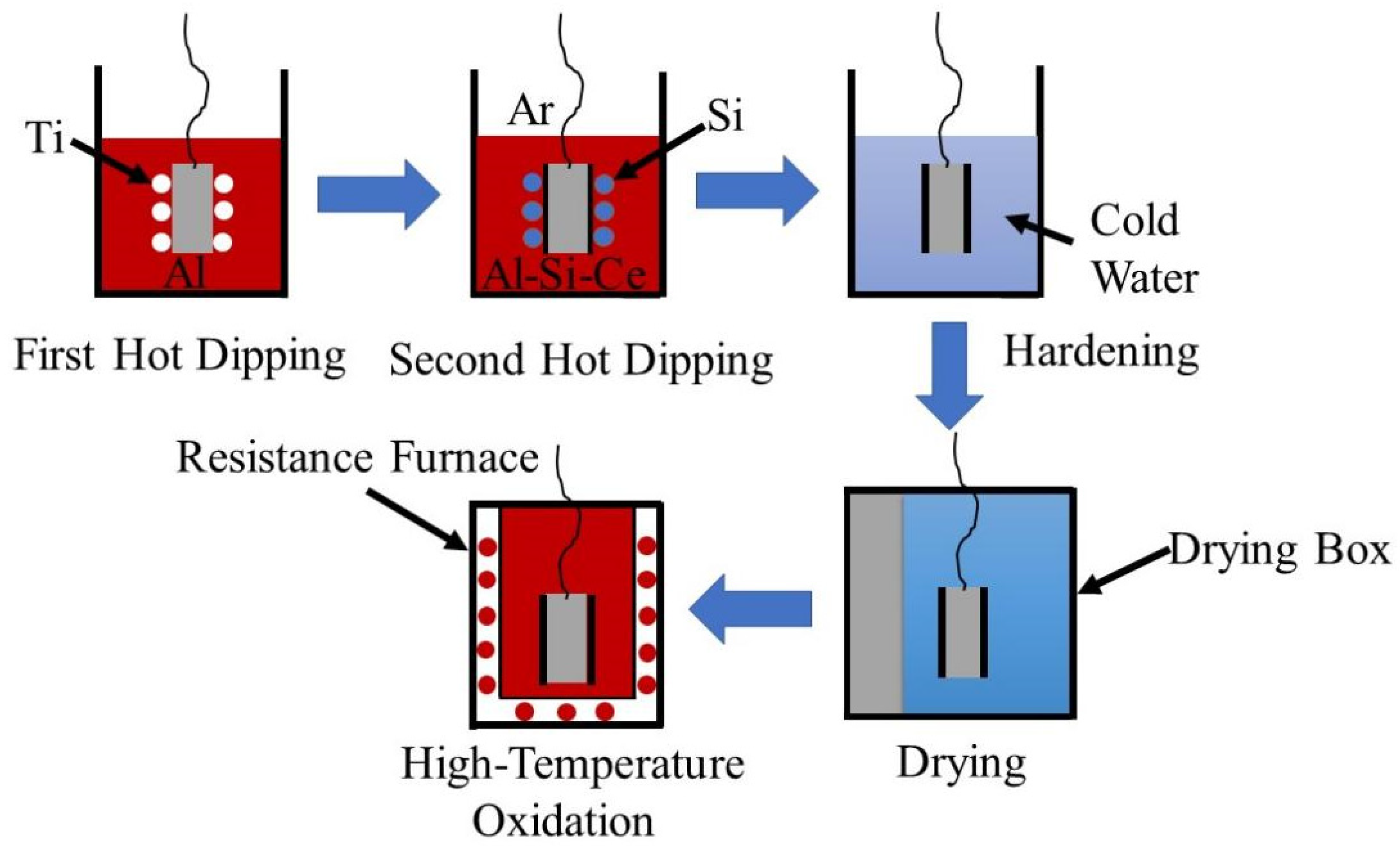
3. Results and Discussion
3.1. Microstructure Characterization of Coatings
3.1.1. Hot-dip Coating Tissue
3.1.2. Growth Kinetics of Coatings
3.2. Microstructure Characterization of High Temperature Pre-oxidation Coating
3.3. High Temperature Oxidation Properties of Coatings
3.3.1. High Temperature Oxidation Coating Morphology
3.3.2. High Temperature Oxidation Kinetics
3.3.3. Crack
3.4. Mechanism of Coating Formation and Resistance to High Temperature Oxidation
3.4.1. The Mechanism of Coating Formation
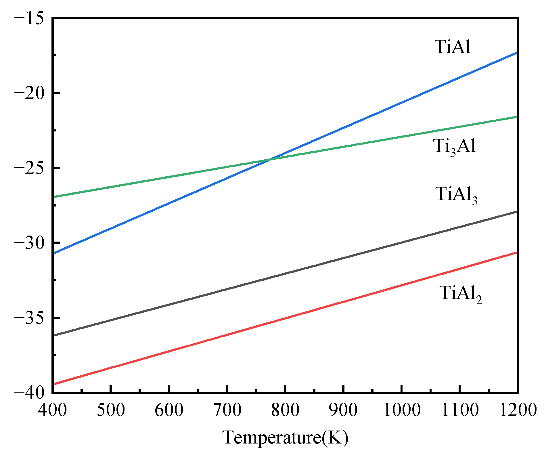
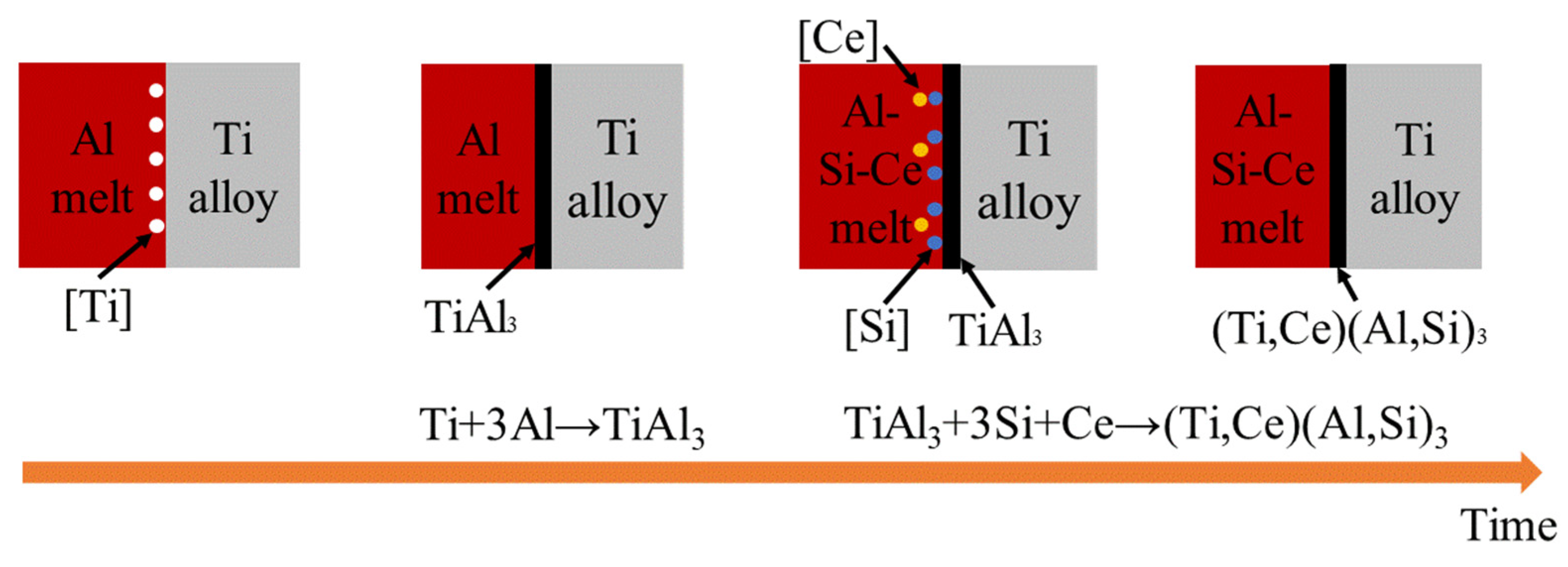
3.4.2. High-Temperature Resistance Mechanism

4. Conclusions
- (1)
- The two-step hot-dip coating is mainly composed of (Ti,Ce)(Al,Si)3 alloy layer. With the increase of the second step hot-dip plating time of Al-10wt.%Si-1wt.%Ce, the alloy layer gradually becomes dense.
- (2)
- In the process of pre-oxidation and high-temperature oxidation, the substrate reacts with (Ti,Ce)(Al,Si)3 alloy layers to form multiple Ti-Al binary system phase layers, among which the dense TiAl3+Ti5Si3 mixed phase layer, dense TiAl layer and dense Ti3Al layer containing Ce element can prevent the crack propagation to the substrate.
- (3)
- During the high-temperature oxidation process, the Ce element combines with Al2O3 in the form of CeO2, which can promote the formation of continuous Al2O3 layer, and the high-temperature oxidation resistance of the Al2O3 layer containing CeO2 is improved.
Author Contributions
Funding
Institutional Review Board Statement
Informed Consent Statement
Data Availability Statement
Acknowledgments
Conflicts of Interest
References
- Zhao, Q.Y.; Sun, Q.Y.; Xin, S.W.; Chen, Y.N.; Wu, C.; Wang, H.; Xu, J.W.; Wan, M.P.; Zeng, W.D.; Zhao, Y.Q. High-strength titanium alloys for aerospace engineering applications: A review on melting-forging process. Mater. Sci. Eng., A 2022, 845, 143260. [Google Scholar] [CrossRef]
- Pushp, P.; Dasharath, S.M.; Arati, C. Classification and applications of titanium and its alloys. Mate. Today 2022, 54, 537–542. [Google Scholar] [CrossRef]
- Wang, Z.H.; Li, F.G.; Hu, X.Y.; He, W.; Liu, Z.; Tan, Y. Preparation of Ti-Al-Si Gradient Coating Based on Silicon Concentration Gradient and Added-Ce. Coatings 2022, 12, 683. [Google Scholar] [CrossRef]
- Luo, S.Y.; Yao, J.; Zou, G.M.; Li, J.; Jiang, J.; Yu, F.P. Transformation characteristics of temperature and phases within Ti-6Al-4V aeroengine drum in hot forging and air cooling procedures. J. Mater. Res. Technol. 2020, 9, 8235–8244. [Google Scholar] [CrossRef]
- Hu, X.Y.; Li, F.G.; Shi, D.M.; Xie, Y.; Li, Z.; Yin, F.C. A design of self-generated Ti–Al–Si gradient coatings on Ti–6Al–4V alloy based on silicon concentration gradient. J. Alloy. Compd. 2020, 830, 154670. [Google Scholar] [CrossRef]
- Wen, P.C.; Yuan, L.J.; Tao, R.; Li, J.; Li, D. First-principles investigation of interaction between surface oxygen and other alloy atoms in α-Ti (0001) for designing high-temperature titanium alloy. Appl. Surf. Sci. 2022, 604, 154535. [Google Scholar] [CrossRef]
- Zhao, E.T.; Sun, S.C.; Zhang, Y. Recent advances in silicon containing high temperature titanium alloys. J. Mater. Res. Technol. 2021, 14, 3029–3042. [Google Scholar] [CrossRef]
- Tian, Y.S.; Zhang, Q.Y.; Wang, D.Y. Study on the microstructures and properties of the boride layers laser fabricated on Ti–6Al–4V alloy. J. Mater. Process. Technol. 2009, 209, 2887–2891. [Google Scholar] [CrossRef]
- Zheng, N.; Fischer, W.; Griibrneier, H.; Shernet, V.; Qiradakkers, W.J. The significance of sub-surface depletion layer composition for the oxidation behavior of g-titanium aluminides, Scr. Metall. Mater. 1995, 33, 47–53. [Google Scholar] [CrossRef]
- Rakowski, J.M.; Pettit, F.S.; Meier, G.H.; Dettenwanger, F.; Schumann, E.; Ruhle, M. The effect of nitrogen on the oxidation of g-TiAl, Spcrita Metall. Mater. 1995, 33, 997–1003. [Google Scholar] [CrossRef]
- Xiang, J.Y.; Xie, F.Q.; Wu, X.Q.; Wang, S.Q.; Li, L. Hot corrosion behavior of a Si Y co-deposition coating on a Ti2AlNb based alloy in NaCl-Na2SO4 mixture. Surf. Coat. Technol. 2021, 419, 127282. [Google Scholar] [CrossRef]
- Pan, C.G.; Fang, C.J.; Shi, J.; Ma, K.J.; Yang, H.; He, P. Synthesis and properties of Ti-Al coating by high-frequency induction heated combustion. J. Alloys Compd. 2023, 939, 168739. [Google Scholar] [CrossRef]
- Zhang, Z.G.; Peng, Y.P.; Mao, Y.L.; Pang, C.J.; Lu, L.Y. Effect of hot-dip aluminizing on the oxidation resistance of Ti–6Al–4V alloy at high temperatures. Corros. Sci. 2012, 55, 187–193. [Google Scholar] [CrossRef]
- Sui, X.M.; Lu, J.; Wei, D.Q.; Zhang, L.; Wang, R.; Zhao, W.; Zhang, W.P. Unveiling the influence of TiN on the microstructure and high-temperature oxidation behavior of Ti-Al-Cr composite coating. Corros. Sci. 2022, 206, 110539. [Google Scholar] [CrossRef]
- Cammarota, G.P.; Casagrande, A.; Sambogna, G. Effect of Ni, Si and Cr in the structural formation of diffusion aluminide coatings on commercial-purity titanium. Surf. Coat. Technol. 2006, 201, 230–242. [Google Scholar] [CrossRef]
- Oukati Sadeq, F.; Sharifitabar, M.; Shafiee Afarani, M. Synthesis of Ti–Si–Al coatings on the surface of Ti–6Al–4V alloy via hot dip siliconizing route. Surf. Coat. Technol. 2018, 337, 349–356. [Google Scholar] [CrossRef]
- Crespo-Villegas, J.; Cavarroc, M.; Knittel, S.; Martinu, L.; Klemberg-Sapieha, J.E. Protective TixSiy coatings for enhanced oxidation resistance of the ɣ-TiAl alloy at 900°C. Surf. Coat. Technol. 2022, 430, 127936. [Google Scholar] [CrossRef]
- Chen, C.; Feng, X.M.; Shen, Y.F. Oxidation behavior of a high Si content Al–Si composite coating fabricated on Ti–6Al–4V substrate by mechanical alloying method. J. Alloys Compd. 2017, 701, 27–36. [Google Scholar] [CrossRef]
- Li, X.T.; Huang, L.J.; Jiang, S.; Gao, Y.N.; An, Q.; Wang, S.; Zhang, R.; Geng, L. Microstructure and super oxidation resistance of the network structured Ti-Al-Si coating. J. Alloys Compd. 2019, 807, 151679. [Google Scholar] [CrossRef]
- Li, Z.H.; Chai, L.J.; Qi, L.; Wang, Y.Y.; Liu, Y.Z.; Yang, T.; Wang, H.; Guo, N.; Zhao, Y.X. Laser-cladded Al-Cr-Ti ternary alloy coatings on Ti-4Al-2V alloy: Specific microstructure and enhanced surface performance. Surf. Coat. Technol. 2023, 452, 129073. [Google Scholar] [CrossRef]
- Du, X.J.; Ma, X.Y.; Ding, X.; Zhang, W.; He, Y.Z. Enhanced high-temperature oxidation resistance of low-cost Fe–Cr–Ni medium entropy alloy by Ce-adulterated. J. Mater. Res. Technol. 2022, 16, 1466–1477. [Google Scholar] [CrossRef]
- He, Y.M.; Lu, C.Y.; Ni, C.Y.; Chen, Q.X.; Zheng, W.J.; Wang, D.H.; Wei, L.F.; Wang, L.M.; Sun, Y.; Zou, H.; Gao, Z.L.; Yang, J.G. Tailoring microstructure and mechanical performance of the TC4 titanium alloy brazed joint through doping rare-earth element Dy into Ti-Cu-Ni filler alloy. J. Manuf. Process. 2020, 50, 255–265. [Google Scholar] [CrossRef]
- Xue, X.Y.; Ma, C.M.; Liu, Y.R.; Wang, H.; Chen, Q.J. Impacts of Ce dopants on the hydrogen storage performance of Ti-Cr-V alloys. J. Alloys Compd. 2023, 934, 167947. [Google Scholar] [CrossRef]
- Xu, Y.; Liu, Z.; Zhu, X.H.; Jiang, Z.L.; Chen, H.; Wang, N. Effect of rare earth Ce addition on microstructure and mechanical properties of titanium alloy Ti-6Al-4V. Mater. Lett. 2023, 330, 133244. [Google Scholar] [CrossRef]
- Marder, A.R. The metallurgy of zinc-coated steel. Prog. Mater. Sci. 2000, 45, 191–271. [Google Scholar] [CrossRef]
- Jeng, S.-C. Oxidation behavior and microstructural evolution of hot-dipped aluminum coating on Ti-6Al-4V alloy at 800°C. Surf. Coat. Technol. 2013, 235, 867–874. [Google Scholar] [CrossRef]
- Kattner, U.R.; Lin, J.C.; Chang, Y.A. Thermodynamic Assessment and Calculation of the Ti-Al System. Metall. Trans. A 1992, 23, 2081–2090. [Google Scholar] [CrossRef]
- Niu, G.D.; Wang, J.; Li, J.P.; Ye, J.W.; Mao, J. Characterization of in-situ reinforced (Al,Si)3(Ti,Ce) precipitates in T6 treated A356-0.3wt.%Ce-1.5vol.%TiCN composite and its effects on mechanical properties. Mater. Charact. [CrossRef]
- Fan, L.; Liu, M.; Wang, Y.L.; Cui, H.B.; Ren, X.D.; Xin, B. Microstructure, mechanical properties and corrosion behavior of Ce doped TiN films. Appl. Surf. Sci. 2022, 575. [Google Scholar] [CrossRef]
- Cheng, W.S.; Song, B.; Mao, J.H. Effect of Ce content on the hydrogen induced cracking of X80 pipeline steel. Int. J. Hydrogen Energy 2023, 48, 15303–15316. [Google Scholar] [CrossRef]
- Guan, Q.; Zhong, F.; Sha, J.B. Effect of Ce addition on hot corrosion behaviours of a cast γ′-strengthened Co–Al–W–Mo–Ta–B alloy at 800 °C. Prog. Nat. Sci.: Mater. Int. 2022, 32, 463–471. [Google Scholar] [CrossRef]
- Wang, S.Q.; Xie, F.Q.; Wu, X.Q.; Chen, L.Y. CeO2 doped Al2O3 composite ceramic coatings fabricated on γ–TiAl alloys via cathodic plasma electrolytic deposition. J. Alloys Compd. 2019, 788, 632–638. [Google Scholar] [CrossRef]
- Shen, H.; Zhou, G.Y.; Cao, G.H.; Luo, M.; Dong, X.M.; Zhang, Z.H. Effects of Ce and La on microstructure and sulfide stress cracking susceptibility of API-5CT-C110 casing steel. Int. J. Hydrogen Energy 2023, 48, 4349–4362. [Google Scholar] [CrossRef]
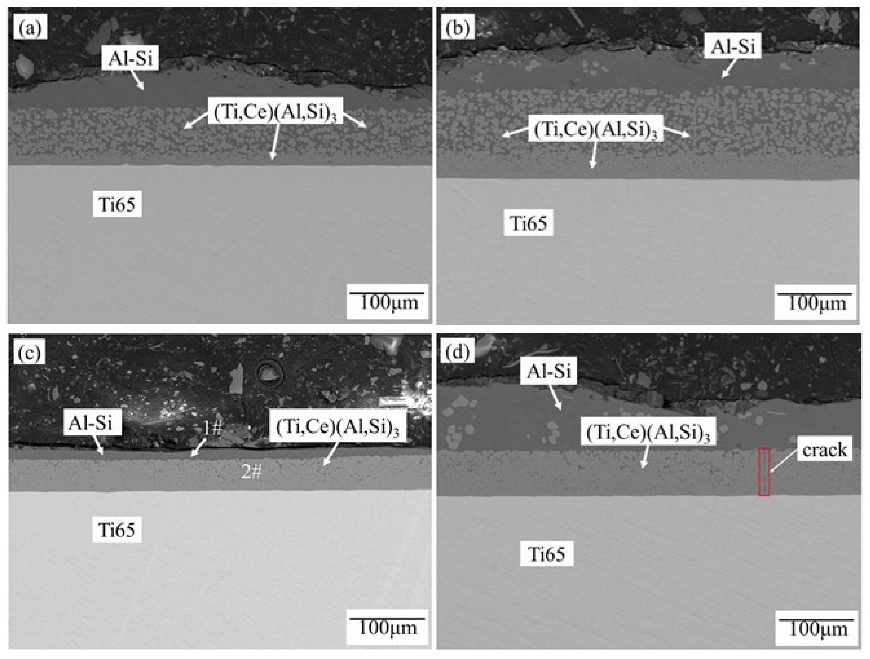
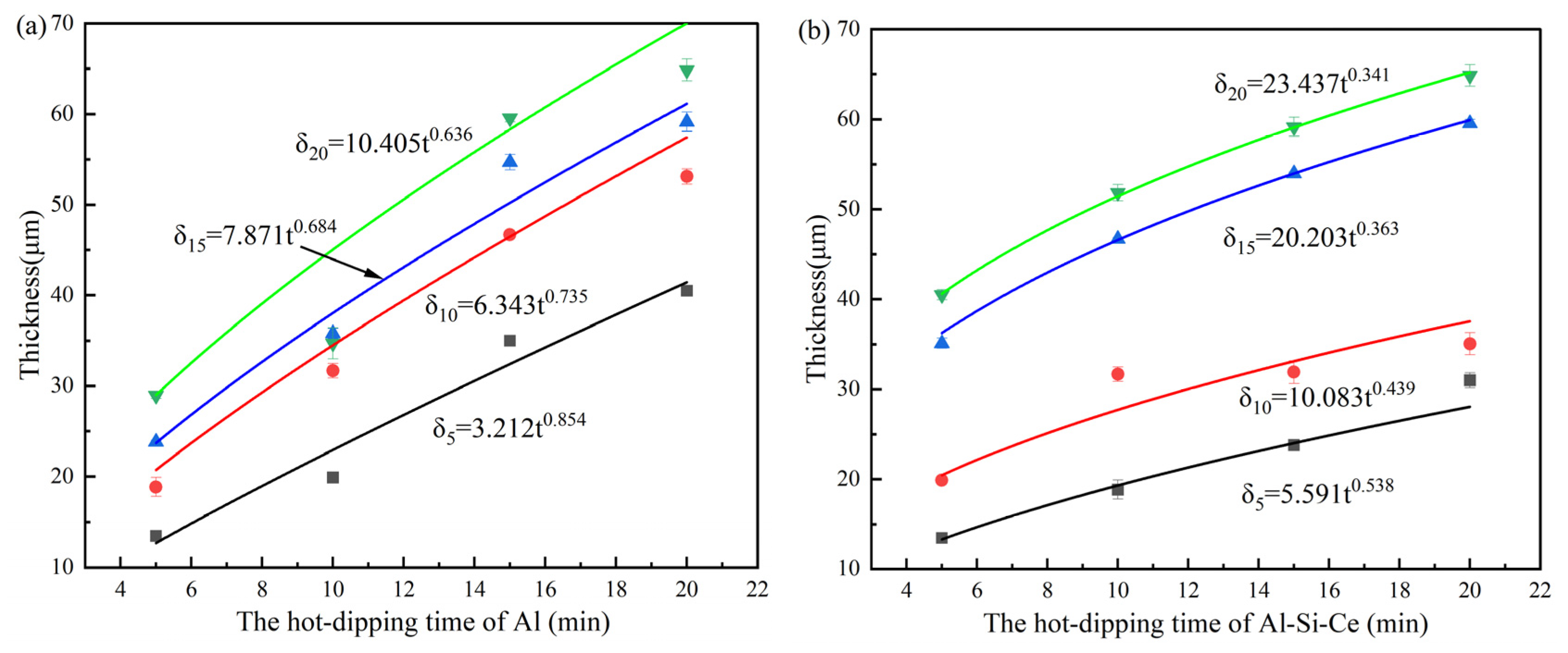
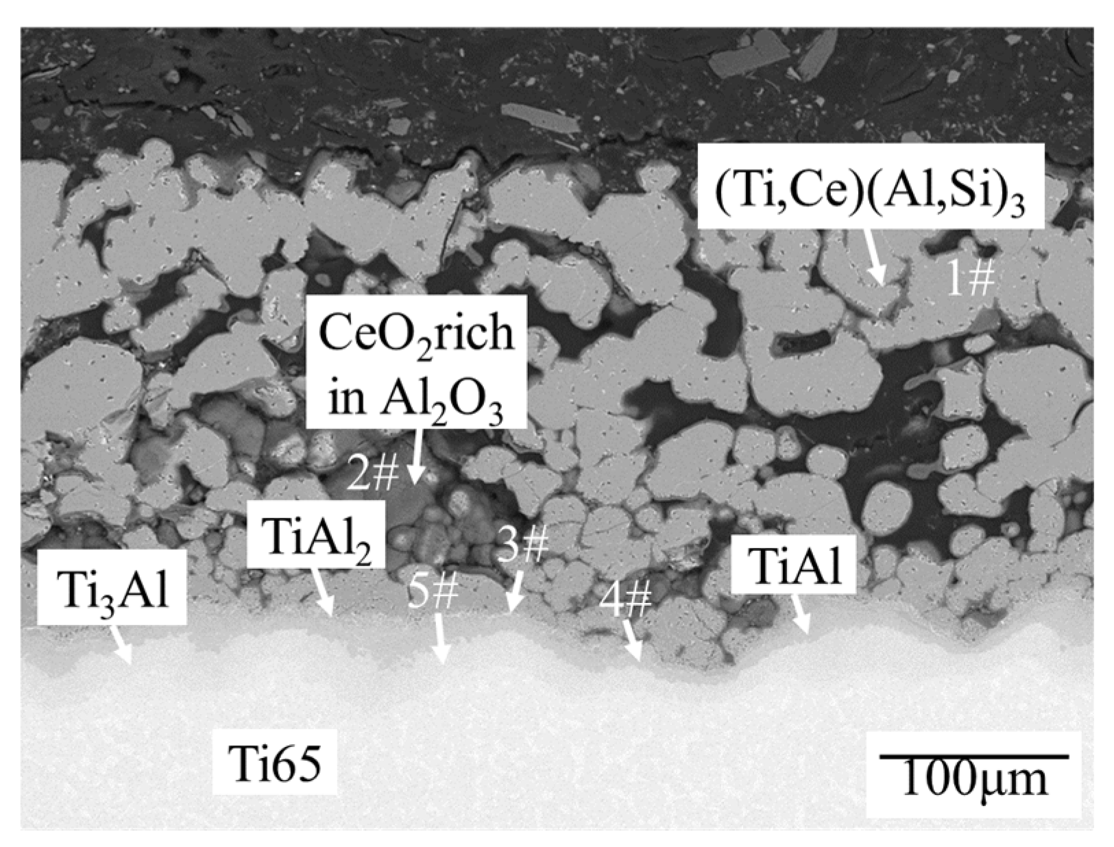
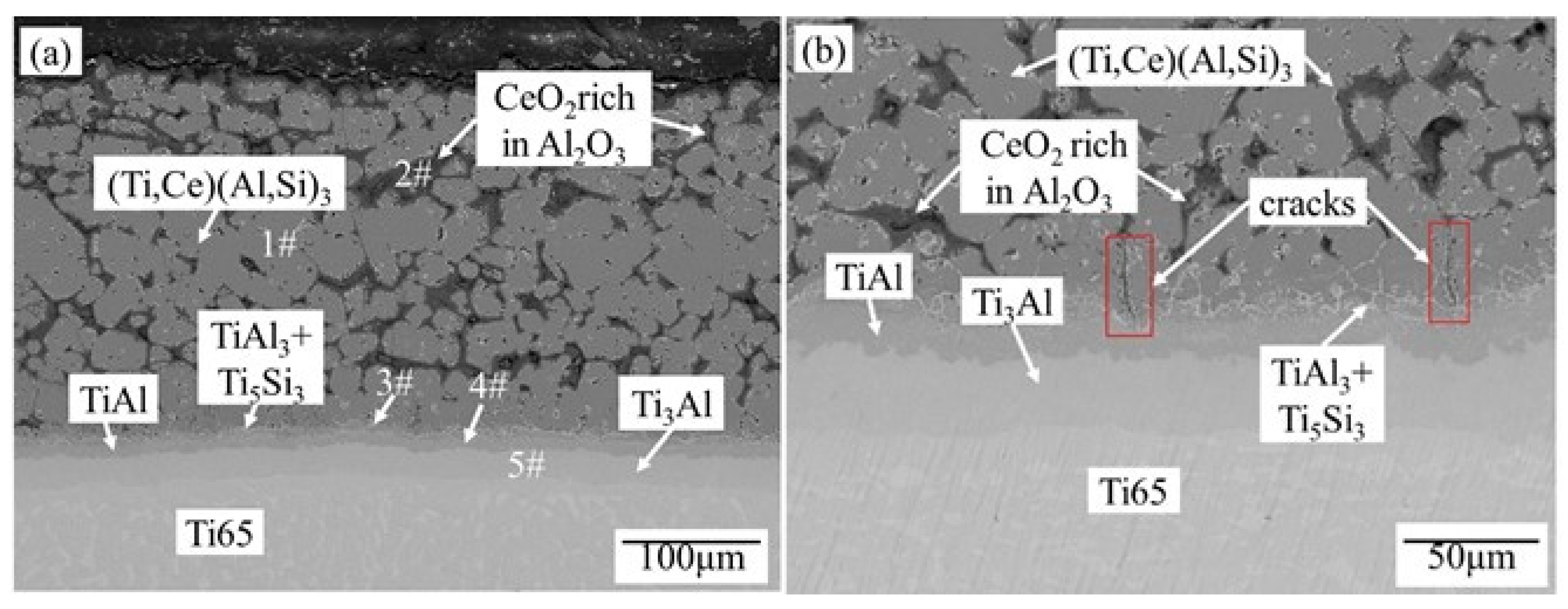
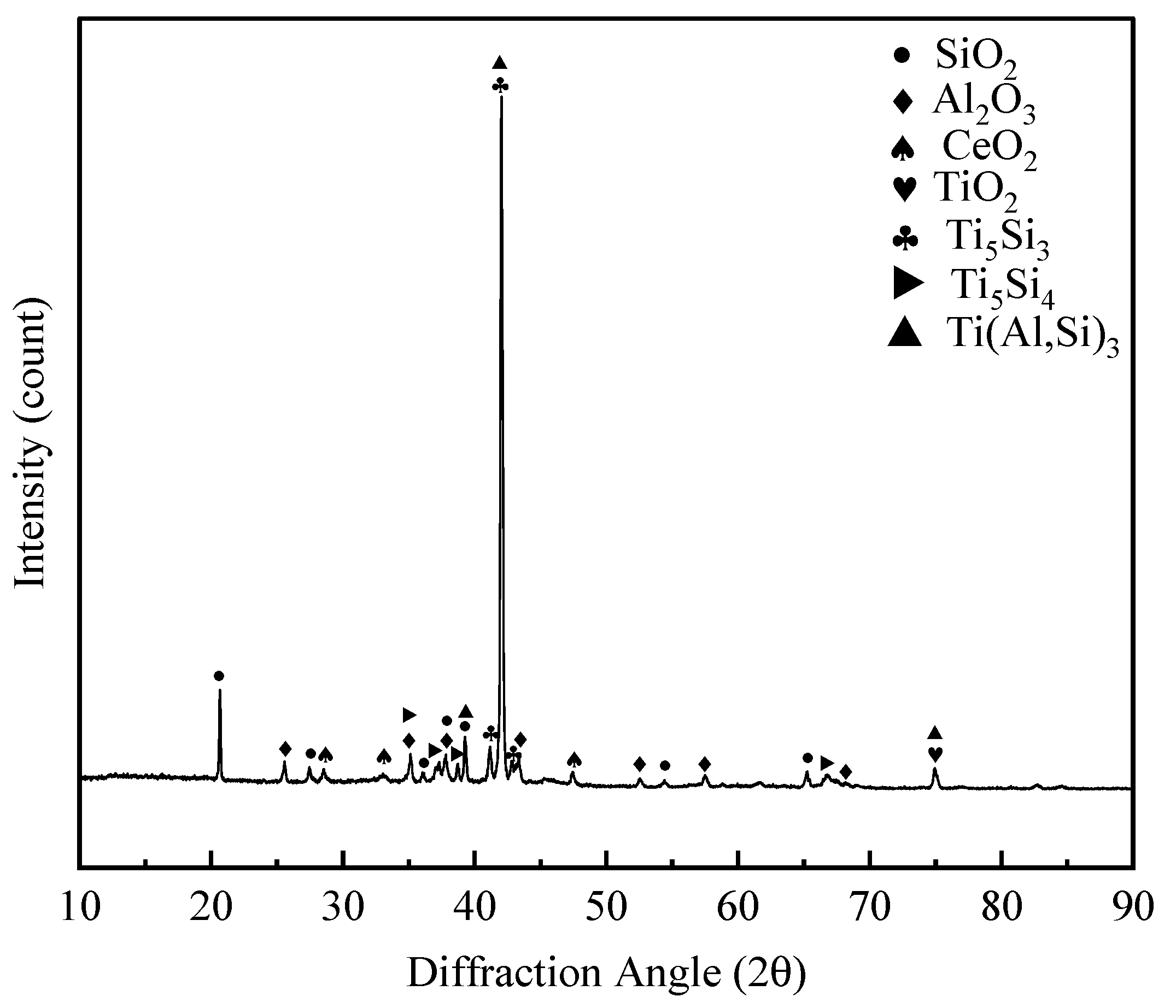
| Analysis Region | Al | Si | Ti | Ce | Phase |
|---|---|---|---|---|---|
| 1# | 99.73 | 0.27 | 0 | 0 | Al-Si |
| 2# | 63.75 | 9.55 | 26.57 | 0.13 | (Ti,Ce)(Al,Si)3 |
| Analysis Region | O | Al | Si | Ti | Ce | Phase |
|---|---|---|---|---|---|---|
| 1# | 0 | 67.51 | 4.77 | 27.63 | 0.09 | (Ti,Ce)(Al,Si)3 |
| 2# | 55.55 | 41.76 | 0 | 2.57 | 0.12 | Al2O3+CeO2 |
| 3# | 0 | 64.24 | 2.13 | 33.57 | 0.06 | TiAl2 |
| 4# | 0 | 41.43 | 2.28 | 55.90 | 0.39 | TiAl |
| 5# | 0 | 20.90 | 0 | 78.88 | 0.22 | Ti3Al |
| Analysis Region | O | Al | Si | Ti | Ce | Phase |
|---|---|---|---|---|---|---|
| 1# | 0 | 66.37 | 3.78 | 29.74 | 0.11 | (Ti,Ce)(Al,Si)3 |
| 2# | 59.96 | 37.59 | 0 | 2.30 | 0.15 | Al2O3+CeO2 |
| 3# | 0 | 36.22 | 20.36 | 43.35 | 0.07 | TiAl3+Ti5Si3 |
| 4# | 0 | 37.55 | 3.93 | 58.28 | 0.24 | TiAl |
| 5# | 0 | 21.18 | 0 | 78.61 | 0.21 | Ti3Al |
Disclaimer/Publisher’s Note: The statements, opinions and data contained in all publications are solely those of the individual author(s) and contributor(s) and not of MDPI and/or the editor(s). MDPI and/or the editor(s) disclaim responsibility for any injury to people or property resulting from any ideas, methods, instructions or products referred to in the content. |
© 2023 by the authors. Licensee MDPI, Basel, Switzerland. This article is an open access article distributed under the terms and conditions of the Creative Commons Attribution (CC BY) license (http://creativecommons.org/licenses/by/4.0/).


