
Submitted:
21 June 2023
Posted:
25 June 2023
You are already at the latest version
Abstract
Acoustic metasurface are artificial structures which could manipulate the wavefront in sub-wavelength dimensions and the previous proposed acoustic metasurface were mostly realized with single materials. An acoustic metasurface with composite structure is proposed for underwater acoustic stealth considering both wavefront manipulation and sound absorption. The unit cells of the metasurface are composed by metallic supporting lattice, interconnecting polymer materials and mass balancing columns. With the gradual modulations of equivalent physical properties along the horizontal direction of metasurface, the incident acoustic wave is reflected to other directions. Meanwhile, the polymer material inside the unit cells would dissipate the acoustic wave energy due to inherent damping properties. With the simultaneous modulations of reflected wave direction and scattering acoustic amplitude, significant improvement of underwater stealth effect is achieved. Compared with single-phase metasurface, the Far-Field Sound Pressure Level (FFSPL) of the multiphase metasurface decreased by 4.82 dB within the frequency range of 3kHz~30kHz. Under a hydrostatic pressure of 5MPa, the linearized mean stress for multiphase metasurface is only 1/3 of that of single-phase metasurface due to much thicker struts and much more uniform stress distribution. The proposed composite structure possesses potential applications due to acceptable thickness (80mm) and low equivalent density (1100 kg/m3).
Keywords:
metamaterials
; pentamode materials
; acoustic metasurface
; dispersion curve
1. Introduction
The acoustic stealth performances of submarines are essential in underwater environments, which are mainly determined by the retro-reflected signals detected by active sonars. Similar with stealth technique for radar detecting, acoustic energy absorptive materials such as anechoic coating is generally adopted to reduce the intensity of retro-reflected signals. Traditional anechoic coating made of rubber or polyurethane substrate with cavities are adopted to absorb the incident detecting wave energy or eliminate the radiated noise of the hull, whose stealth performance tends to be very weak at low frequency and higher hydrostatic pressure [1,2]. Thick and heavy anechoic coating is demanded to achieve strong absorption at low frequency as limited by laws of mass, which is unimplementable for most underwater vehicles.
Local resonant metamaterial can manipulate long wavelength acoustic waves within subwavelength scale based on resonance of resonators [3]. The intensive vibrating of the resonators around the resonance frequency would lead to strengthened energy dissipating and strong acoustic absorption consequently. Inspired by this mechanism and introducing viscoelasticity of substrate, low frequency waterborne strong absorption is realized by Wen et al. with a sub-wavelength sample [4], but the inferiority is that the effective frequency bandwidth is very narrow. A lot of studies have been done to expand the effective frequency bandwidth by introducing multi-resonators [5,6,7,8,9], metal spiral and inter-connecting structures [10,11,12], air cavities and combinations of them [13,14,15,16,17]. For example, combining two absorption mechanisms of cavity resonance and impedance transition loss, Wang et al. proposed a broadband underwater absorbing metamaterial with gradient cavity array supported by carbon fiber honeycomb [15], which achieved a broadband sound absorption under a hydrostatic pressure of 3MPa. Zhang et al. proposed a waterborne stealth coating with transversely arranged single-walled carbon nanotubes to broaden the effective absorption range [16]. Fan et al. also proposed an acoustic absorption–bearing metamaterial consisted by four subunits corresponding to different absorption frequencies and obtained an absorption bandwidth increased by 600% [17]. These new designs expanded the effective bandwidth greatly, but still suffers from many issues such as hydrostatic resistance, manufacturing techniques and cost, density, thickness restrictions, etc.
Acoustic metasurface is a gradient-index artificial structure capable of manipulating acoustic waves in an extraordinary way within compact sizes [18,19,20,21], demonstrating promising applications in many practical scenarios such as noise and vibration insulation [22,23,24,25], underwater acoustic stealth [26,27,28], surveying and imaging [29,30,31]. The acoustic stealth principle of local-resonance method is similar with air cavity-resonance principle, where the incident acoustic energy is absorbed and the intensities of retro-reflected signals is diminished. Instead of acoustic energy absorption, acoustic metasurface could deflect the incident detecting wave into other direction through gradual modulation of phase and amplitude, which also reduce the retro-reflected acoustic signal intensities received by the detecting sonar. Thus, the proposal of acoustic metasurface provides an alternative avenue to eliminate the retro-reflected sound waves. Acoustic metasurface is composted by many sub-units of gradual varying sizes, where both resonant-based and non-resonant based configurations are adopted for sub-units designing. Utilizing thermal loss of air, simultaneous modulations of wavefront and amplitude is achieved for airborne acoustic metasurface [32,33]. While for waterborne metasurface, the effective frequency range of resonance-based designs is very small. Thus, non-resonant designs based on pentamode material (PM) is proposed and adopted for metasurface design.
Pentamode material (PM) is a special solid acoustic metamaterial with the merits of broadband efficiency and matched impedance with fluids. For a solid material, none of six eigenvalues of elastic modulus equals zero, while for pentamode material only one eigenvalue of six ones is nonzero [34]. Benefiting from the arbitrarily tailorable equivalent elastic matrix and mass density [35], PM can be utilized to construct many different types of acoustic devices especially in acoustic metasurface. Practically, PM acoustic devices are mainly composed by 2D honeycomb-lattice structures [36,37]. Chen et al. designed a broad PM acoustic cloaking with a titanium alloy substrate, which is proved to be effective in the frequency range of 9kHz~15kHz [38]. Zhao et al. conceived a PM device based on a titanium alloy (Ti-6Al-4V) mimicking the acoustic properties of water within the frequency range of 3kHz~30kHz [39,40]. Su et al. designed a waterborne pentamode focusing lens, whose broadband focusing effects are experimentally verified within the frequency range of 20~40 kHz [41]. Chen et al. proposed a broadband and high-transmission metasurface for converting underwater cylindrical waves to plane waves over a broad frequency band of 15~23 kHz [42]. Sun et al. designed underwater acoustic bend and carpet with PM [43]. Zhang et al. designed a waterborne acoustic reflective metasurface, which could shift incident waves by an angle of 15° over the frequency range of 6~18 kHz, showing great coincidences of experimental measurements with the finite-element simulations [44]. Except honeycomb-lattice unit cells, a series of novel PM unit cells with square and triangle lattices are proposed by Dong et al. with a systematic inverse-design strategy [45]. Based on the optimization procedure, a reflective metasurface capable of absorbing broadband waterborne sound are conceived and numerically validated [46,47]. Ren et al. designed a broadband high-efficient gradient lens with square-latticed pentamode metamaterial, which could convert plane waves to subwavelength focusing over an ultra-wide frequency range of 5~33 kHz [48].
The above PM devices are realized with single-phase substrate, Zhao et al. proposed a multiphase PM configuration composed by metallic supporting lattice, interconnecting phase and mass balancing block [49]. Then, a multiphase PM structure is fabricated and experimentally verified, which demonstrate the robustness of multiphase PM configuration [50,51]. Yet in these studies, hard polymer (E≈1GPa) whose damping coefficient is very small is adopted and the damping of the substrates and structures is ignored.
In this paper, a novel multiphase PM metasurface which could simultaneously manipulate acoustic wavefront and dissipate incident acoustic energy is proposed. Based on the Generalized Snell Law, a directional reflection acoustic metasurface is proposed, whose physical properties are realized with single-phase and multiphase pentamode unit cells furtherly. Damping coefficient is introduced and the corresponding acoustic properties are assessed by COMSOL Multiphysics. The advantages of the multiphase metasurface are illustrated on the viewpoint of acoustic stealth performance, pressure resistance under high hydrostatic pressure. Results of this paper are profit to promote the practical application of underwater acoustic metasurface.
2. Materials and Methods
In this section, the principle of the Generalized Snell Law is presented based on which the physical properties of the abnormal reflection metasurface is derived. Then the geometrical configuration of the single-phase and multiphase pentamode material are conceived. Finally, the method for equivalent physical properties calculation and the Simulated Annealing (SA) algorithm for optimization is described detailly.
2.1. Generalized Snell Law (GSL)
When a plane acoustic wave impinges on the proposed metasurface, the relationship between the incident wave and reflected wave would follow Generalized Snell Law (GSL), which can be expressed as:
Where ni is the refraction index of the incident medium, θi and θr denotes the incident and reflected angles, λi is the wavelength. x is the transversal coordinate along the metasurface, Φ(x) denotes the phase variation accumulation and is the phase gradient of reflected wave. m is the order of the diffraction peak.
With the Generalized Snell Law, a directional reflection acoustic metasurface could be proposed as presented in Figure 1. The incident angle is set as θi = 0°. The phase accumulation of the wave along the transversal direction of metasurface can be calculated as:
where D is the thickness of metasurface, f and c are the frequency and velocity of the wave.
K(x) and ρ(x) is the bulk modulus and density of the metasurface along the transversal direction. The impedance of metasurface should equal to that of background medium:
Combining (1), (2) and (3), the properties of the metasurface are expressed as:
Where Const is an integration constant, indicating that the same wavefront modulation function could be obtained with different values of K and ρ.
2.2. Configurations of unit cells
The principle for metasurface design is to introduce a designable phase-gradient profile along the surface, by which the behavior of the reflected wave can be manipulated. The design procedure of metasurface is shown in Figure 2. Analytical solution based on Equation (4) is proposed firstly as shown in Figure 2a, where continual physical parameters (the modulus K(x) and the density ρ(x)) are derived. Then the parameters along the transversal direction were discretized while the vertical direction is homogeneous (Ki, ρi), as shown in Figure 2b. The physical parameters (Ki, ρi) have a specified combination, which are not available for existing nature materials generally. Thus, artificial structures with equivalent modulus and equivalent density are desired for in acoustic metasurface realizations. Honeycomb cells with additional weights are the mostly adopted cell configuration designing as shown in Figure 3a, where the thickness of struts determines the desired modulus K and the desired density ρ was adjusted by the mass of the additional weights. Thus, PM acoustic metasurface designed with single materials are gradient structures with varying hexagonal latticed microstructures as shown in Figure 2c, which are mostly fabricated by cutting hexagonal centimeter scale hollow microstructures from a single piece of rigid plates (usually metals) as shown in Figure 2d. It is seen that strut thickness changes gradually according to the distribution of the physical parameters.
Single-phase materials are reported for pentamode device designing and fabrication in the previous studies. As can be found in most previous works, the metasurface is always constructed from a series of individually conceived subunits, which is usually a passive and lossless acoustic device because the subunits of the metasurface is usually lossless. If unit cells with inherent damping are introduced, a metasurface capable of wave energy loss could also be designed. For waterborne acoustic metasurface, metallic materials with low damping properties are generally adopted as substrate of single-phase configuration, which would lead to a lossless metasurface. Thus, dual-phase and triple-phase pentamode configurations are proposed by the authors as shown in Figure 3b,c in this paper. The unit cell is composed by three materials: the matrix material (metallic alloys in most cases, providing the desired stiffness for the unit cell), damping material (polymeric materials), balancing material (materials with very high density and low modulus are usually adopted, which acts as balancing weight needed for unit cell designing). The cell geometry of the multiphase pentamode cell is characterized by length H of the vertical strut, length L of the two tilted struts, angle θ between tilted struts and horizontal line, vertical strut thickness tH, tilted strut thickness tL, the radius R of the hollow circle or balancing material.
The cell geometry of the single-phase pentamode unit (Figure 3a) is characterized by the following parameters:
The two multiphase pentamode configurations presented in Figure 3b,c are depicted by the following parameters:
2.3. Method for equivalent physical properties calculation
The equivalent density of unit cell ρequ could be calculated by the areas and densities of each material in the unit cell. Homogenization theory is adopted to obtain the equivalent modulus κequ firstly, but the studies revealed that the calculated results is only accurate in the long wavelength condition (low frequency range), while the deviation would be huge at higher frequency due to dynamic effect. Thus, dispersion curves are preferred on deriving the equivalent dynamic modulus κequ, which is accepted and adopted by most researchers. Dispersion curve reveals the relations between frequency (ω) and wave vector (k), and from the slope we could deduce the phase velocities (c=ω/k) corresponding to different vibration modes or waves. In the long-wave condition (k ≈ 0), the slopes of the transverse acoustic wave (TA, cT) and the longitudinal acoustic wave (LA, cL) are calculated. For isotropic media in continuum mechanics, the phase velocities of the compression wave, cL, and the shear wave, cT, are given by:
From Equation (7), the equivalent bulk modulus and shear modulus are derived.
Aluminum alloy (E=69 GPa, v= 0.33, and ρ=2700 kg/m3) is adopted as the matrix material, thermoplastic polyurethanes (TPU, E=100 MPa, v=0.4, and ρ=1000 kg/m3) is adopted as the damping material, and lead columns (E=16 GPa, v= 0.42, and ρ=11300 kg/m3) is adopted as the balancing weight material. When an isotropic structure is desired, some parameters are fixed for simplification during optimization: H = L = 10 mm, θ=30°, tH = tL. Typical dispersion curves of the unit cells calculated using Bloch-Floquet analysis in COMSOL are presented in Figure 4a. The dot lines are fits to the compression and shear waves in the long-wavelength limit, respectively.
The parametric design of PM microstructure given a specific combination of equivalent modulus and density (Ki, ρi) is an inverse problem, and several variables in both single-phase and multiphase PM configurations need to be determined. Due to the numerous combinations of design space, optimization methods are urgent when finding the optimal design variables. The optimization of PM is a classic global optimization problem, where random sets of feasible solutions are generated in the optimization process and local convergence needs to be avoided. A gradient-free method, Simulated Annealing (SA) technique, is adopt in this study to solve the optimization problems. SA optimization method is inspired by mimicking the thermodynamic process of metal annealing, which was conceived by Metropolis et al. and developed by Kirkpatrick et al. [52,53,54]. A methodology based on a combination of dispersion curve and SA optimization technique is developed to perform the optimal study of PM configurations. The optimization methodology is implemented by COMSOL with MATLAB. For a given set of design variables, the effective properties are derived by dispersion curve. The objective function could be calculated from Equation (4). SA algorithm integrated with COMSOL is developed to implement the optimization process in an iterative manner. Accordingly, the flow chart of SA optimization procedure is present in Figure 4d and the detailed description is introduced in a previous work [51].
3. Results and discussions
In this section, the influences of damping coefficient on acoustic properties of ideal metasurface are interpreted from the aspects of scattering acoustic pressure field map and Far-Field Sound Pressure Level in the frequency range of 3~30 kHz. Then metasurface with single-phase and multiphase configurations are designed based on the methodology described in Section 2, whose acoustic properties are numerically investigated and quantitatively verified respectively. Finally, the hydrostatic resistance of both two metasurface are displayed in terms of stress distribution under the same hydrostatic pressure.
3.1. Influences of damping coefficient on acoustic properties of ideal metasurface
In this paper, an aluminum block with L=693.2mm and Db=70mm is adopted as the rigid wall, while the thickness of the metasurface is D=80mm. The angle of incident wave is set as θi = 0°, while the angle of reflective angle is set as θr = 15°. The properties of the metasurface are derived from formula (4), where the densities vary from 0.5677ρ0 to 1.6323ρ0 and the bulk modulus vary from 1.7616κ0 to 0.6126κ0. The average equivalent density of the metasurface is about 1.10ρ0, which is acceptable in underwater applications. The acoustic properties are investigated by COMSOL Multiphysics. A full 2D geometry is used in the “Acoustics-solid, Frequency Domain” module. The isotropic structural damping coefficient ηs is endowed to the material via the subnode of “Linear Elastic Material”. Perfectly matched layers are imposed on the outer boundaries of simulation domains to eliminate reflections. The metasurface is set on the upper surface of the aluminum block, while the incident wave impinges on the models from up to down.
The scattering acoustic pressure field map of the metasurface at 10kHz, 20kHz and 30 kHz are shown in Figure 5. For aluminum block, extensive scattering existed at all the frequencies, and the maximum scattering pressure exits in the incident direction as presented in Figure 5a–c. For the continual metasurface derived from theory, an obvious deflection of scattering wave is observed as shown in Figure 5d–f and the reflection angle is about 15°, which is the same as that of theoretical design. Continual material properties are unavailable in practice. Therefore, discretization is a crucial step in practical realization of metasurface. In this study, the continual metasurface is divided into 20 pieces, during each piece the material property is identical and the corresponding parameters are presented in Table 1. The density increases from the left to right, while bulk modulus varies oppositely. The simulation results of discretized metasurface are illustrated in Figure 5g–i. No obvious difference is observed between continual metasurface and discretized metasurface from the acoustic field map, and the successive quantitative calculation will also prove the conclusion. A damping coefficient of 0.1 and 0.2 are introduced in the material properties, and the simulation results are presented in Figure 5j–l and Figure 5m–o. It is seen that the amplitude of the scattering acoustic pressure is reduced obviously, especially at high frequencies.
To assess the acoustic behaviors of the metasurface quantitatively, Far-Field Sound Pressure Level (FFSPL) are calculated in the frequency range of 3~30 kHz. FFSPL is a measure of the scattering pressure of a target, which is usually quantified as a number of negative decibels (dB). FFSPL is defined as follows:
where is reference pressure, and is the acoustic pressure of scattering wave at a distance of r0 from the center.
The polar plots of FFSPL for aluminum block and different metasurface are presented in Figure 6. The maximum FFSPL appear in the azimuth angle of 90° for aluminum block and 75° for various metasurface, which are in agreement with the results in Figure 5. The polar curve of continual metasurface is almost identical with that of discretized metasurface, and the maximum FFSPL are very close to that of aluminum block. It is demonstrated that the metasurface can deflect the propagation direction of the reflected wave without dissipating the acoustic energy. The maximum FFSPL of two metasurface with damping also appear in the azimuth angle of 75°, and the value decreased with the increase of damping coefficient. The results reveal that the introduction of damping in metasurface can reduce the amplitude of reflected acoustic wave without altering the wave manipulation ability.
The above conclusions also suggest a potential application in acoustic stealth of submarines, where only the retro-reflected acoustic signals are considered. The directional reflecting metasurface with damping could deflect the scattering acoustic wave to other direction, avoiding being detected, meanwhile the inherent damping properties will also diminish the intensities of the scattering acoustic wave. FFSPL is also adopted to assess the acoustic stealth ability of the metasurface. In order to ensure the robustness of results, the average value of FFSPL in the range of 90°±3° is adopted in the assessment and the results are illustrated in Figure 7. The FFSPL of metasurface is smaller than that of aluminum block above 3kHz (corresponding to a wavelength of 0.5m, a bit smaller than the length of the metasurface), and a reduction of 10dB is achieved for most calculated frequencies. Continual metasurface and discretized metasurface without damping yield almost the same results. The average FFSPL of aluminum block in the frequency range of 3kHz~30kHz is 111.79, while that of continual metasurface and discretized metasurface is 95.97dB and 97.46dB, respectively. With the introduction of damping, the FFSPL diminished obviously as the damping coefficient increases. The average FFSPL is 94.15dB and 91.95dB corresponding to a damping coefficient of 0.1 and 0.2. Compared with discretized metasurface without damping, the introduction of damping will result in a further reduction of 5.51dB on the basis of scattering wave reflection. Thus, it is concluded from the simulation results that the introduction of damping will enhance the acoustic stealth performance of the metasurface significantly.
3.2. Microstructure design of single-phase and multiphase metasurface
With the methodology mentioned in Section 2.3, the geometrical parameters of single-phase unit cells corresponding to 20 pieces of metasurface are obtained and presented in Table 1. The thickness of the struts diminishes gradually, while the additional mass block increases inversely. Four typical dispersion curves of single-phase unit cells are presented in Figure 8. For each piece, there are two cells in the horizontal direction and five cells in the vertical direction. The whole geometrical picture of the single-phase metasurface and 5 typical unit cells are presented in Figure 9.
In previous studies, only single-phase substrate was considered and the damping coefficient of substrate was seldom considered duo to very small values (for metallic materials the damping coefficient is about 0.005). In the design of multiphase configurations, the damping coefficient of the polymer material is too large to be ignored. For thermoplastic polyurethanes (TPU), the damping coefficient is larger than 0.1 at almost all the frequencies, and even larger than 1.0 at high frequencies. Thus, the effect of damping coefficient should be assessed quantitatively before the design of multiphase configurations. Two cells corresponding to dual-phase configuration (No.5) and tri-phase configuration (No.16) are presented in Figure 10 to demonstrate the effect of damping coefficient. The damping coefficient of TPU is set as 0.2. It is shown from the dispersion curves that there is only tiny difference. Quantitative calculation reveals that the consideration of damping will result in an increase of longitudinal wave velocity in the range of 0.1% ~ 0.2%, which could be neglected in microstructure design.
Similar with the design of single-phase unit cells, the geometrical parameters of multiphase cells corresponding to 20 pieces of metasurface are also obtained and presented in Table 1. The first 11 cells are dual-phase configurations, while the last 9 cells are tri-phase configurations (lead column is introduced to achieve the desired density). The final geometrical picture of the multiphase metasurface and 5 typical unit cells are presented in Figure 11.
3.3. Formatting of Mathematical Components
The scattering acoustic pressure field maps of the single-phase and multiphase metasurface at 10kHz, 20kHz and 30 kHz are shown in Figure 12. The values of FFSPL at different frequencies are also calculated and presented in Figure 13.
For single-phase metasurface, the scattering acoustic pressure field maps are similar with those of discretized metasurface shown in Figure 5. The azimuthal angles of the reflected wave are about 15° at 10kHz and 20kHz, but there is a slight variation at 30kHz and the azimuthal angle turns out to be about 13°. As quantitatively presented in Figure 13a, the FFSPL of single-phase metasurface is much larger than that of discretized metasurface beyond 25kHz, suggesting the influence of chromatic dispersion at high frequencies. This phenomenon can be explained by the dispersion curves presented in Figure 8. It is seen that for unit cells with thick struts (Figure 8a,b), the slope of longitudinal wave will keep as a constant over a very broad frequency range, suggesting that the equivalent properties are effective in this frequency range. While for unit cells with thinner struts (Figure 8c,d), the effective frequency range is much smaller, which will cause adverse influence in wave manipulation. Figure 8d indicates that the slope of longitudinal wave varies gradually beyond 25kHz, below which the slopes of longitudinal wave for all the 20 cells are constants. Thus, each unit cell will exhibit the desired properties and the wave control functionality is guaranteed. Beyond 25kHz, the slopes of longitudinal wave for some unit cells no longer keep as a constant. Therefore, the cells will exhibit great deviation from desired physical properties and cause adverse effect on wave control functionality. The average FFSPL over the frequency range of 3kHz~30kHz is 98.60dB, which is only 1.14dB higher than that of discretized metasurface without damping. The simulation results indicate the effectiveness of the single-phase metasurface and validity of the design method.
For multiphase metasurface without considering the damping behavior of TPU, the wave control functionality is well exhibited below 12kHz, above which the azimuthal angle of reflected wave reduces gradually and results in much larger FFSPL, as indicated from Figure 12d–f and Figure 13b. This phenomenon can be also explained by the dispersion curves. It is seen from Figure 10 that the chromatic dispersion appears at much lower frequency. The equivalent acoustic properties of the designed cells can be guaranteed at low frequencies, and the azimuthal angle of reflected wave is in accord with theoretical design. The introduction of damping will not change the wave control functionality as indicated by Figure 12g–l, but would abate the amplitude of the scattering acoustic wave efficiently as indicated by Figure 13c,d. The average FFSPL for multiphase metasurface, multiphase metasurface with a damping coefficient of 0.1, multiphase metasurface with a damping coefficient of 0.2 are 99.85dB, 96.27dB, 93.78dB, respectively. Compared with single-phase metasurface, the average FFSPL of multiphase metasurface with a damping coefficient of 0.2 decreases by 4.82dB, which demonstrating great advantages in practical application.
3.4. Advantages on withstanding hydrostatic pressure
Under a hydrostatic pressure of 5MPa, the stress distributions of the single-phase and multiphase metasurface are presented in Figure 14 (The maximum mesh size is 0.1 mm). For both two metasurface, the cells with thinner struts will present higher stress and linearized mean stress along the thickness direction of the struts is adopted to assess the stress distribution level. For single-phase metasurface the linearized mean stress is about 251 MPa, while the that of the triple-phase MW is only about 74.2 MPa. The results could be also deduced from the parameter design results shown in Table 1, where the thinnest strut of multiphase metasurface is 0.58mm, almost twice of that of single-phase metasurface (0.30 mm). Except for thicker strut, the presence of polymer materials and lead columns inside the unit cells will also result in much more uniform and smaller stress distribution. It is seen that under the same hydrostatic pressure, the mean stress in the multiphase metasurface is much smaller and therefore much safer in deep-sea environments.
4. Conclusions
In conclusion, a novel underwater multiphase metasurface which could manipulate the wavefront and dissipate the acoustic energy simultaneously was proposed. The study suggested that the proposed multiphase metasurface could improve the acoustic stealth ability significantly, which have great potential in underwater applications. The main conclusions are summarized as follows:
(1) A multiphase pentamode configuration composed of hexagonal latticed microstructures, polymer materials and mass balancing lead columns was proposed to realize the desired physical properties. Compared with the single-phase pentamode unit cell which was mostly designed with metallic materials and the damping coefficient was relatively small, significant damping is introduced in the configuration design. Besides, more degree of freedom was introduced which facilitated the designing of metasurface.
(2) An abnormal directional reflection metasurface with a length of 693.2mm and width of 80mm was proposed and numerically verified. Both the simulation results of scattering acoustic pressure field map and Far-Field Sound Pressure Level (FFSPL) in the frequency range of 3kHz~30kHz revealed that the metasurface could reflect the scattering acoustic wave by an the azimuth angle of 15°, which was in agreement with the original design. It was also shown that the introducing of material damping won’t alter the direction of scattering acoustic wave, but it could abate the scattering acoustic pressure amplitude obviously.
(3) Both multiphase and single-phase metasurfaces were designed for the same theoretical metasurface. It is revealed that both metasurface demonstrated the abilities of altering scattering acoustic wave propagation direction, but the amplitude of the scattering wave couldn’t be abated for single-phase metasurface due to no damping properties of the single-phase unit cell. Utilizing the damping properties of the polymer materials inside the multiphase unit cells, the multiphase metasurface could abate the amplitude of scattering acoustic pressure on the basis of reflecting scattering wave. Quantitative calculations reveal that the average Far-Field Sound Pressure Level for single-phase metasurface decreased by 13.19dB compared with aluminum block within the frequency range of 3kHz~30kHz, while that of multiphase metasurface decreased by 4.82dB compared with single-phase metasurface.
(4) The pressure resistance capabilities of both two metasurfaces were studied and compared. It was illustrated that under the same hydrostatic pressure the linearized mean stress for multiphase metasurface is only about 1/3 of that of single-phase metasurface, which suggested that the metasurface designed with multiphase configuration could withstand three times of hydrostatic pressure than the one designed with single-phase unit cell.
Author Contributions
An Yi: Conceptualization, Methodology, Software, Writing – original draft. Han Zou: Methodology, Investigation. Aiguo Zhao: Project administration, Supervision, Funding acquisition, Writing – review & editing.
Funding
This research received no external funding.
Institutional Review Board Statement
Not applicable.
Informed Consent Statement
Not applicable.
Data Availability Statement
The data that support the findings of this study are available from the corresponding author upon reasonable request.
Acknowledgments
The authors would like to thank the editor, associate editor, and the anonymous reviewers for their helpful comments and suggestions that have improved this paper.
Conflicts of Interest
The authors declare no conflict of interest.
References
- Fu, Y.; Kabir, I.I.; Yeoh, G.H.; Peng, Z. A review on polymer-based materials for underwater sound absorption. Polym. Test. 2021, 96, 107115. [Google Scholar] [CrossRef]
- Wang, Y.; Miao, X.; Jiang, H.; Chen, M.; Meng, D. Review on underwater sound absorption materials and mechanisms. Adv. Mech. 2017, 47, 92. [Google Scholar]
- Bai, H.; Zhan, Z.; Liu, J.; Ren, Z. From Local Structure to Overall Performance: An Overview on the Design of an Acoustic Coating. Materials 2019, 12, 2509. [Google Scholar] [CrossRef]
- Wen, J.; Zhao, H.; Lv, L.; Yuan, B.; Wang, G.; Wen, X. Effects of locally resonant modes on underwater sound absorption in viscoelastic materials. J. Acoust. Soc. Am. 2011, 130, 1201. [Google Scholar] [CrossRef] [PubMed]
- Zhang, Y.; Huang, H.; Zheng, J.; Pan, J. Underwater sound scattering and absorption by a coated infinite plate with attached periodically located inhomogeneities. J. Acoust. Soc. Am. 2015, 138, 2707. [Google Scholar] [CrossRef]
- Liu, Y.; Xu, W.; Chen, M.; Yang, T.; Wang, K.; Huang, X.; Jiang, H.; Wang, Y. Three-dimensional fractal structure with double negative and density-near-zero properties on a subwavelength scale. Mater. Des. 2020, 188, 108470. [Google Scholar] [CrossRef]
- Sharma, G.S.; Skvortsov, A.; MacGillivray, I.; Kessissoglou, N. Sound absorption by rubber coatings with periodic voids and hard inclusions. Appl. Acoust. 2019, 143, 200. [Google Scholar] [CrossRef]
- Lin, H.-C.; Lu, S.-C.; Huang, H.-H. Evaluation of a Hybrid Underwater Sound-Absorbing Metastructure by Using the Transfer Matrix Method. Materials 2023, 16, 1718. [Google Scholar] [CrossRef]
- Gu, Y.; Zhong, H.; Bao, B.; Wang, Q.; Wu, J. Experimental investigation of underwater locally multi-resonant metamaterials under high hydrostatic pressure for low frequency sound absorption. Appl. Acoust. 2021, 172, 107605. [Google Scholar] [CrossRef]
- Chen, M.; Meng, D.; Zhang, H.; Jiang, H.; Wang, Y. Resonance-coupling effect on broad band gap formation in locally resonant sonic metamaterials. Wave. Motion. 2016, 63, 111. [Google Scholar] [CrossRef]
- Zhang, F.; Sun, X.; Tao, W.; Wang, S.; Flowers, G.T.; Hu, Q.; Gaidai, O. Meta-Structure Hull Design with Periodic Layered Phononic Crystals Theory for Wide-Band Low-Frequency Sound Insolation. Materials 2023, 16, 4429. [Google Scholar] [CrossRef] [PubMed]
- Li, L.; Zhang, Z.; Huang, Q.; Li, S. A sandwich anechoic coating embedded with a micro-perforated panel in high-viscosity condition for underwater sound absorption. Compos. Struct. 2020, 235, 111761. [Google Scholar] [CrossRef]
- Gao, N.; Lu, K. An underwater metamaterial for broadband acoustic absorption at low frequency. Appl. Acoust. 2020, 169, 107500. [Google Scholar] [CrossRef]
- Zhu, Y.; Zhao, X.; Mei, Z.; Li, H.; Wu, D. Investigation of the Underwater Absorption and Reflection Characteristics by Using a Double-Layer Composite Metamaterial. Materials 2023, 16, 49. [Google Scholar] [CrossRef]
- Wang, Z.; Huang, Y.; Zhang, X.; Li, L.; Chen, M.; Fang, D. Broadband underwater sound absorbing structure with gradient cavity shaped polyurethane composite array supported by carbon fiber honeycomb. J. Sound Vib. 2020, 479, 115375. [Google Scholar] [CrossRef]
- Zhang, Z.; Li, Z.; Li, T.; Huang, Q. A novel semi-analytical approach for predicting the sound absorptions of a new underwater composite coating with transversely arranged SWCNTs. Compos. Struct. 2021, 274, 114335. [Google Scholar] [CrossRef]
- Fan, J.; Song, B.; Zhang, L.; Wang, X.; Zhang, Z.; Wei, S.; Xiang, X.; Zhu, X.; Shi, Y. Structural design and additive manufacturing of multifunctional metamaterials with low-frequency sound absorption and load-bearing performances. Int. J. Mech. Sci. 2023, 238, 107848. [Google Scholar] [CrossRef]
- Kildishev, A.V.; Boltasseva, A.; Shalaev, V.M. Planar photonics with metasurfaces. Science 2013, 339, 6125. [Google Scholar] [CrossRef] [PubMed]
- Zhou, H.; Fu, W.; Li, X.; Wang, Y.; Wang, Y. Loosely coupled reflective impedance metasurfaces: Precise manipulation of waterborne sound by topology optimization. Mech. Sys. Sig. Pro. 2022, 177, 109228. [Google Scholar] [CrossRef]
- Cai, M.; Liu, X.; Hu, G.; Zhou, P. Customization of two-dimensional extremal materials, Mater. Des. 2022, 217, 110657. [Google Scholar]
- Li, Z.; Luo, Z.; Zhang, L.; Wang, C. Topological design of pentamode lattice metamaterials using a ground structure method. Mater, Des. 2021, 202, 109523. [Google Scholar] [CrossRef]
- Fang, Y.; Zhang, X.; Zhou, J. Acoustic porous metasurface for excellent sound absorption based on wave manipulation. J. Sound Vib. 2018, 434, 273–283. [Google Scholar] [CrossRef]
- Duan, H.; Yang, F.; Shen, X.; Yin, Q.; Wang, E.; Zhang, X.; Yang, X.; Shen, C.; Peng, W. Acoustic Metamaterials for Low-Frequency Noise Reduction Based on Parallel Connection of Multiple Spiral Chambers. Materials 2022, 15, 3882. [Google Scholar] [CrossRef]
- Zhou, W.; Wang, S.; Wu, Q.; Xu, X.; Huang, X.; Huang, G.; Liu, Y.; Fan, Z. An inverse design paradigm of multi-functional elastic metasurface via data-driven machine learning. Mater. Des. 2023, 226, 111560. [Google Scholar] [CrossRef]
- Wu, X.; Wen, Z.; Jin, Y.; Rabczuk, T.; Zhuang, X.; Djafari, B. Broadband Rayleigh wave attenuation by gradient metamaterials. Int. J. Mech. Sci. 2021, 205, 106592. [Google Scholar] [CrossRef]
- Jiang, S.; Guo, D.; Zhang, L.; Li, K.; Song, B.; Huang, Y. Electropolishing-enhanced, high-precision 3D printing of metallic pentamode metamaterials. Mater. Des. 2022, 223, 111211. [Google Scholar] [CrossRef]
- Chen, Z.; Yan, F.; Negahban, M.; Zheng, L. Resonator-based reflective metasurface for low-frequency underwater acoustic waves. J. Appl. Phys. 2020, 128, 055305. [Google Scholar] [CrossRef]
- Wu, B.; Chen, B.; Ma, S.; Zhang, D.; Zu, H.-R. An Ultra-Broadband and Highly-Efficient Metamaterial Absorber with Stand-Up Gradient Impedance Graphene Films. Materials 2023, 16, 1617. [Google Scholar] [CrossRef]
- Wu, X.; Xia, X.; Tian, J.; Liu, Z.; Wen, W. Broadband reflective metasurface for focusing underwater ultrasonic waves with linearly tunable focal length. Appl. Phys. Lett. 2016, 108, 163502. [Google Scholar] [CrossRef]
- Chen, J.; Rao, J.; Lisevych, D.; Fan, Z. Broadband ultrasonic focusing in water with an ultra-compact metasurface lens. Appl. Phys. Lett. 2019, 114, 104101. [Google Scholar] [CrossRef]
- Yu, G.; Qiu, Y.; Li, Y.; Wang, X.; Wang, N. Underwater acoustic stealth by a broadband 2-bit coding metasurface. Phys. Rev. A 2021, 15, 064064. [Google Scholar] [CrossRef]
- Fang, Y.; Zhang, X.; Zhou, J.; Guo, J.; Huang, X. Acoustic metaporous layer with composite structures for perfect and quasi-omnidirectional sound absorption. Compos. Struct. 2019, 223, 110948. [Google Scholar] [CrossRef]
- Yuan, T.; Song, X.; Xu, J.; Pan, B.; Sui, D.; Xiao, H.; Zhou, J. Tunable acoustic composite metasurface based porous material for broadband sound absorption. Compos. Struct. 2022, 298, 116014. [Google Scholar] [CrossRef]
- Miltion, G.W.; Cherkaev, A.V. Which elasticity tensor are realizable. J. Eng. Mater. Tech. 1995, 117, 483–493. [Google Scholar] [CrossRef]
- Gokhale, N.H.; Cipolla, J.L.; Norris, A.N. Special transformations for pentamode acoustic cloaking. J. Acoust. Soc. Am. 2012, 132, 2932–2941. [Google Scholar] [CrossRef] [PubMed]
- Zhang, L.; Song, B.; Zhao, A.; Liu, R.; Yang, L.; Shi, Y. Study on mechanical properties of honeycomb pentamode structures fabricated by laser additive manufacturing: Numerical simulation and experimental verification. Compos. Struct. 2019, 226, 111199. [Google Scholar] [CrossRef]
- Amendola, A.; Smith, C.J.; Goodall, R.; Auricchio, F.; Feo, L.; Benzoni, G.; Fraternali, F. Experimental response of additively manufactured metallic pentamode materials confined between stiffening plates. Compos. Struct. 2016, 142, 254–262. [Google Scholar] [CrossRef]
- Chen, Y.; Zheng, M.; Liu, X.; Bi, Y.; Sun, Z.; Xiang, P.; Yang, J.; Hu, G. Broadband solid cloak for underwater acoustics. Phys. Rev. B 2017, 95, 180104. [Google Scholar] [CrossRef]
- Cai, X.; Wang, L.; Zhao, Z.; Zhao, A.; Zhang, X.; Wu, T.; Chen, H. The mechanical and acoustic properties of two-dimensional pentamode metamaterials with different structural parameters. Appl. Phys. Lett. 2016, 109, 131904. [Google Scholar] [CrossRef]
- Zhao, A.; Zhao, Z.; Zhang, X.; Cai, X.; Wang, L.; Wu, T.; Chen, H. Design and experimental verification of a water-like pentamode material. Appl. Phys. Lett. 2017, 110, 011907. [Google Scholar] [CrossRef]
- Su, X.; Norris, A.N.; Cushing, C.W. Broadband focusing of underwater sound using a transparent pentamode lens. J. Acoust. Soc. Am. 2017, 141, 4408–4417. [Google Scholar] [CrossRef] [PubMed]
- Chen, Y.; Hu, G. Broadband and high-transmission metasurface for converting underwater cylindrical waves to plane waves. Phys. Rev. Appl. 2019, 12, 044046. [Google Scholar] [CrossRef]
- Sun, Z.; Sun, X.; Jia, H.; Bi, Y.; Yang, J. Quasi-isotropic underwater acoustic carpet cloak based on latticed pentamode metafluid. Appl. Phys. Lett. 2019, 114, 094101. [Google Scholar] [CrossRef]
- Zhang, X.; Chen, H.; Zhao, Z.; Zhao, A.; Cai, X. Wang, L. Experimental demonstration of a broadband waterborne acoustic metasurface for shifting reflected waves. J. Appl. Phys. 2020, 127, 174902. [Google Scholar] [CrossRef]
- Dong, H.; Zhao, S.; Miao, X.; Shen, C.; Zhang, X.; Zhao, Z.; Zhang, C.; Wang, Y.; Cheng, L. Customized broadband pentamode metamaterials by topology optimization. J. Mech. Phys. Solids 2021, 152, 104407. [Google Scholar]
- Dong, H.; Zhao, S.; Oudich, M.; Shen, C.; Zhang, C.; Cheng, L.; Wang, Y.; Fang, D. Reflective metasurfaces with multiple elastic mode conversions for broadband underwater sound absorption. Phys. Rev. Appl. 2022, 17, 044013. [Google Scholar] [CrossRef]
- Zhou, H.; Fu, W.; Li, X.; Wang, Y.; Wang, Y. Loosely coupled reflective impedance metasurfaces: Precise manipulation of waterborne sound by topology optimization. Mech. Sys. Sig. Pro. 2022, 177, 109228. [Google Scholar] [CrossRef]
- Ren, Z.; Dong, H.; He, X.; Chen, M.; Fang, D. Underwater gradient metalens for broadband subwavelength focusing. Int. J. Mech. Sci. 2022, 229, 107521. [Google Scholar] [CrossRef]
- Zhao, A.; Zhang, X.; Yu, W.; Zhao, Z.; Cai, X.; Chen, H. Design and simulation of broadband multiphase pentamode metamaterials. Appl. Phys. Lett. 2021, 118, 224103. [Google Scholar] [CrossRef]
- Zhao, A.; Jia, H.; Zhang, M.; Wang, Z.; Zhou, P.; Liu, C.; Zhao, Z.; Zhang, X.; Wu, T.; Chen, H.; Liu, B.; Song, B. Design and experimental verification of a broadband multiphase pentamode material. Phys. Rev. Appl. 2022, 18, 034001. [Google Scholar] [CrossRef]
- Zhao, A.; Liu, C.; Zou, H.; Jia, H.; Zhang, M.; Wu, T.; Chen, H.; Zhang, X.; Wang, Z. Massive and fast fabrication of pentamode devices through a multiphase honeycomb-corrugation configuration. Mater. Des. 2023, 228, 111816. [Google Scholar] [CrossRef]
- Kirkpatrick, S.; Gelatt, C.; Vecchi, M. Optimization by simulated annealing. Science 1983, 220, 671–680. [Google Scholar] [CrossRef] [PubMed]
- Zhou, W.; Wang, S.; Wu, Q.; Xu, X.; Huang, X.; Huang, G.; Liu, Y.; Fan, Z. An inverse design paradigm of multi-functional elastic metasurface via data-driven machine learning. Mater. Des. 2023, 226, 111560. [Google Scholar] [CrossRef]
- Jung, J.; Goo, S.; Kook, J. Design of a local resonator using topology optimization to tailor bandgaps in plate structures. Mater. Des. 2020, 191, 108627. [Google Scholar] [CrossRef]
Figure 1.
Schematics of normal incident wave and directional reflected wave under the manipulation of a metasurface and backwall.
Figure 1.
Schematics of normal incident wave and directional reflected wave under the manipulation of a metasurface and backwall.
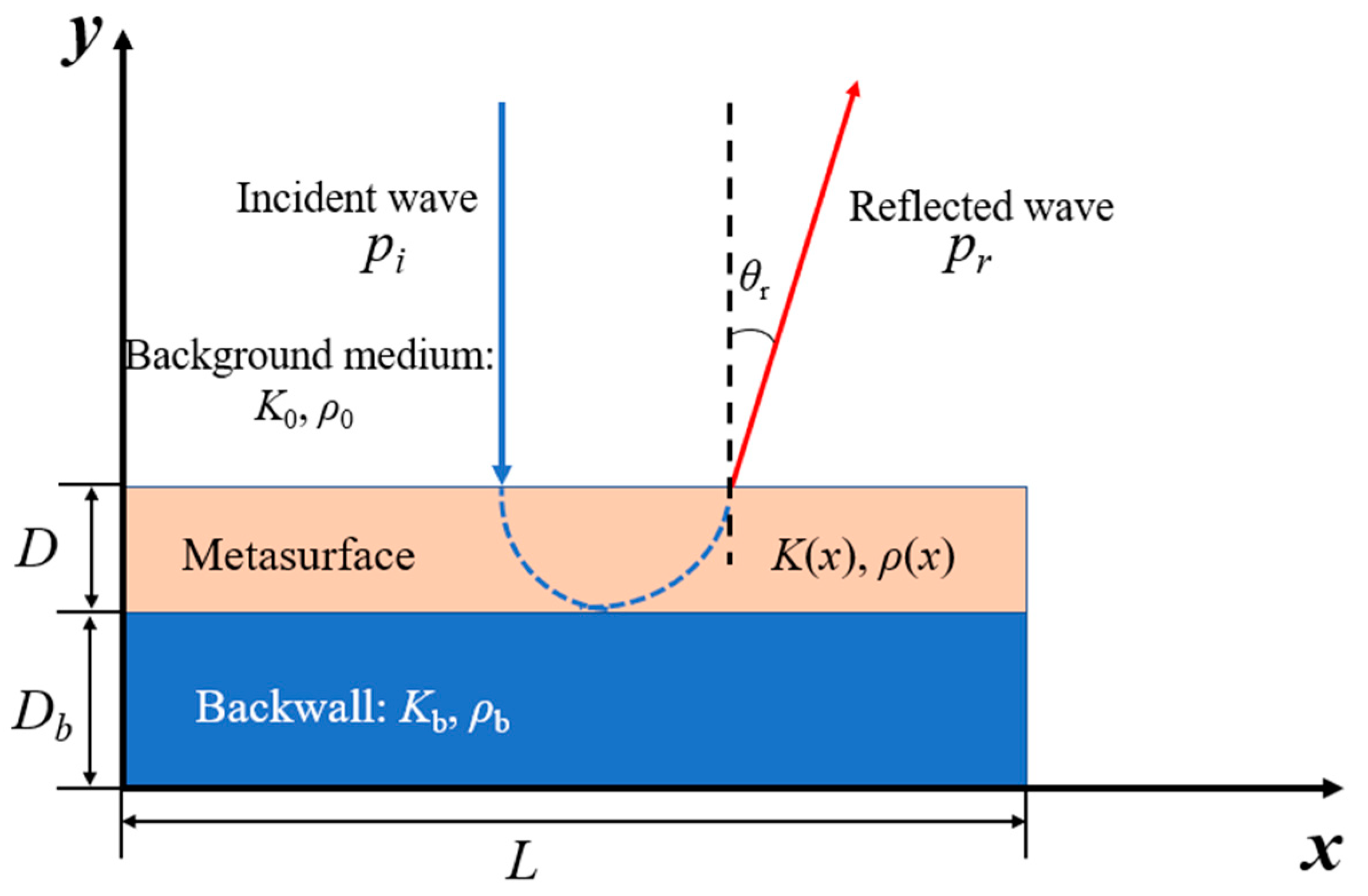
Figure 2.
General design procedure for pentamode metasurface devices. (a) Continual physical parameters results obtained from analytical solution. (b) Discretized physical parameters. (c) Unit cell design and the construction of gradient latticed device. (d) Fabrication of latticed pentamode device.

Figure 3.
Schematics of two-dimensional pentamode microstructures. (a) Single-phase (SP) pentamode configuration. (b) Dual-phase pentamode configuration. (c) Triple-phase (TP) pentamode configuration.
Figure 3.
Schematics of two-dimensional pentamode microstructures. (a) Single-phase (SP) pentamode configuration. (b) Dual-phase pentamode configuration. (c) Triple-phase (TP) pentamode configuration.
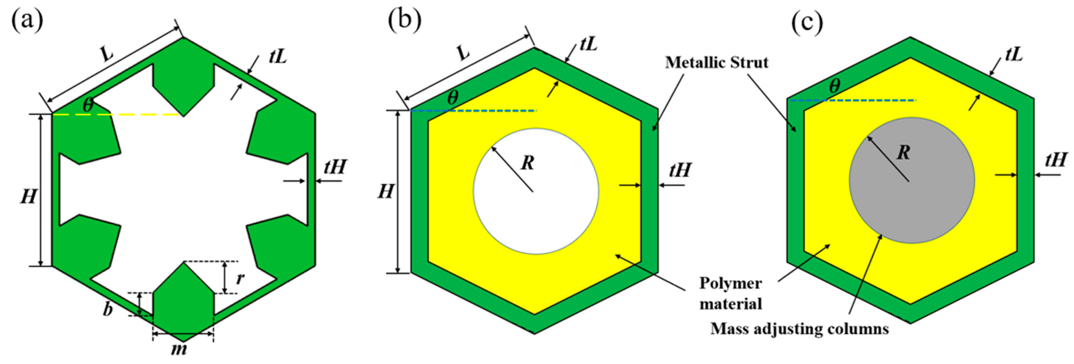
Figure 4.
(a) Typical dispersion curve for acoustic metamaterials. (b) The flow chart of SA optimization [51].
Figure 4.
(a) Typical dispersion curve for acoustic metamaterials. (b) The flow chart of SA optimization [51].
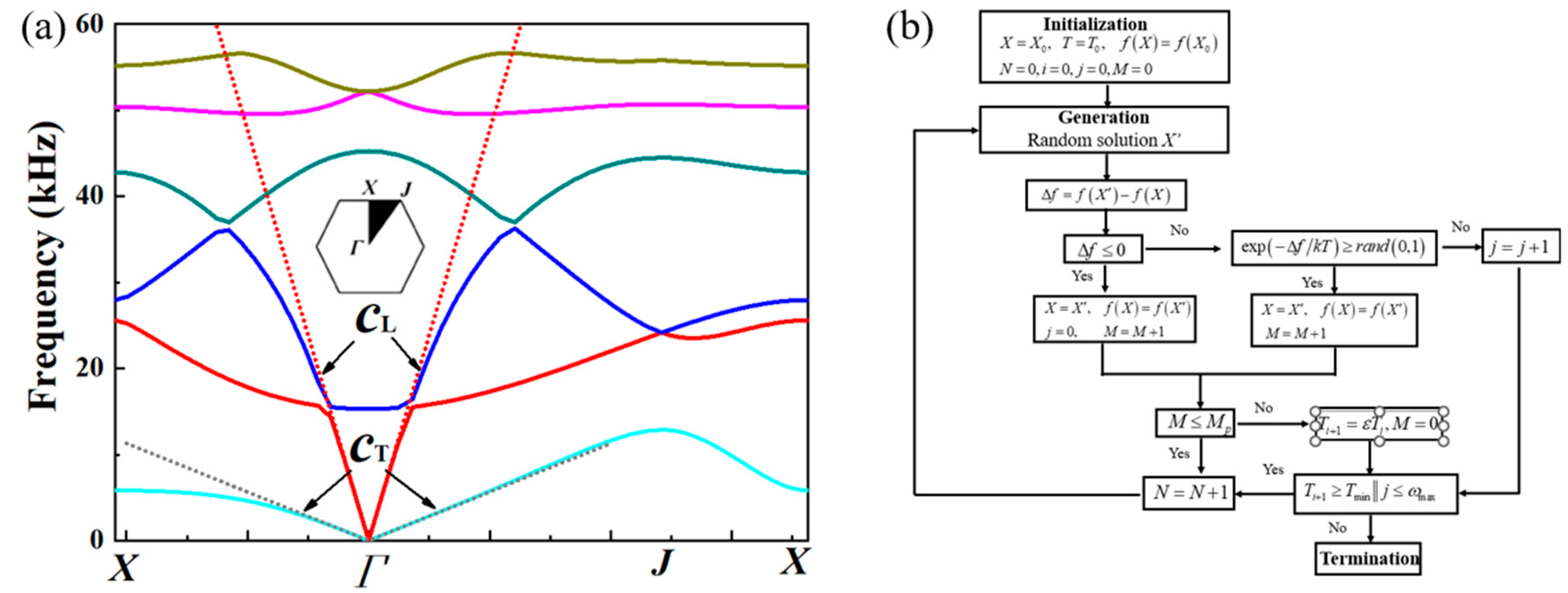
Figure 5.
The scattering acoustic pressure field map of the metasurface at 10kHz, 20kHz and 30 kHz. (a) ~ (c): Aluminum block. (d) ~ (f): Continual metasurface. (g) ~ (i): Discretized metasurface. (j) ~ (l): Discretized metasurface with damping coefficient of 0.1. (m) ~ (o): Discretized metasurface with damping coefficient of 0.2.
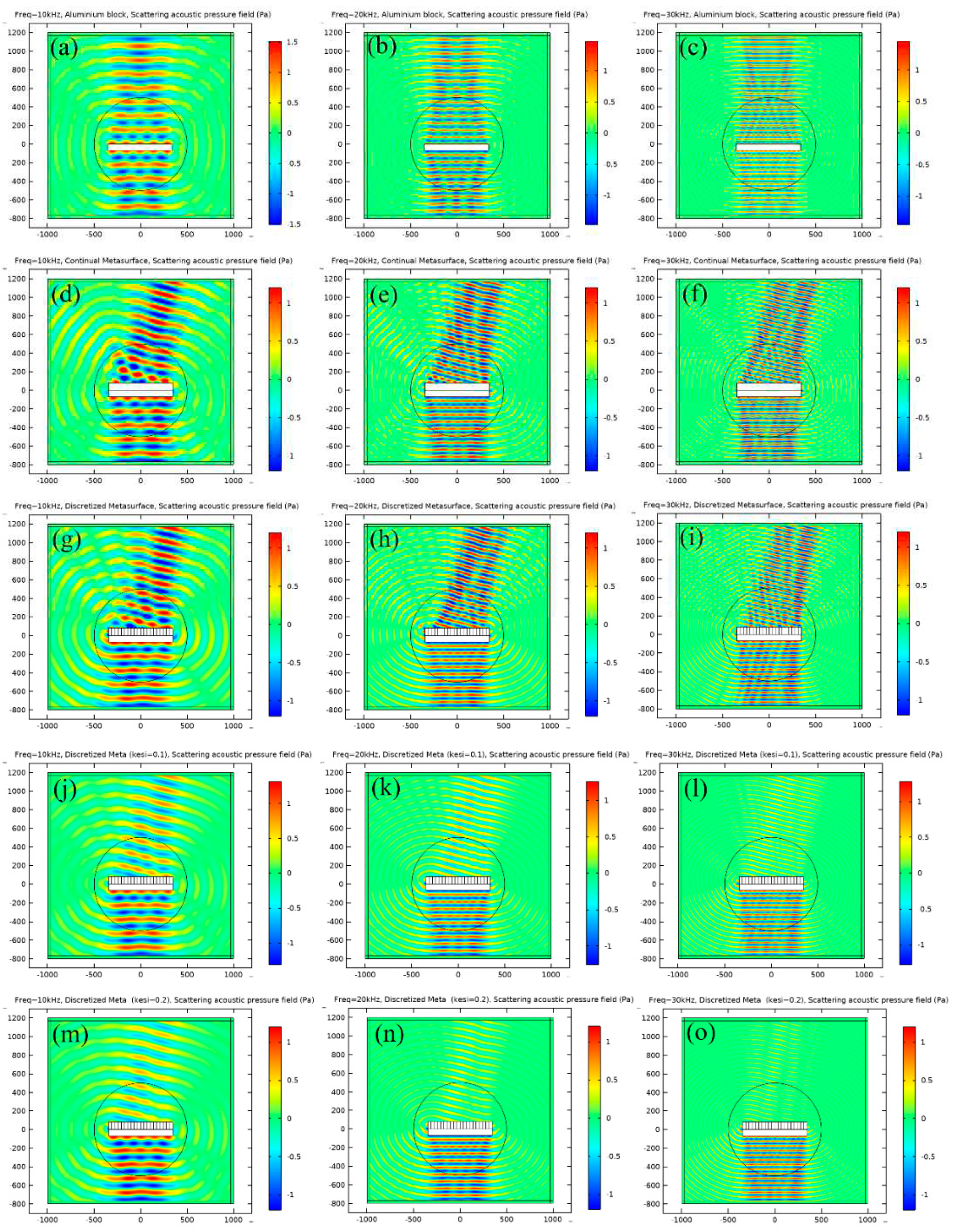
Figure 6.
The polar plot of Far-Field Sound Pressure Level (FFSPL) of aluminum block and metasurface at (a) 10kHz, (b) 20kHz and (c) 30 kHz.
Figure 6.
The polar plot of Far-Field Sound Pressure Level (FFSPL) of aluminum block and metasurface at (a) 10kHz, (b) 20kHz and (c) 30 kHz.
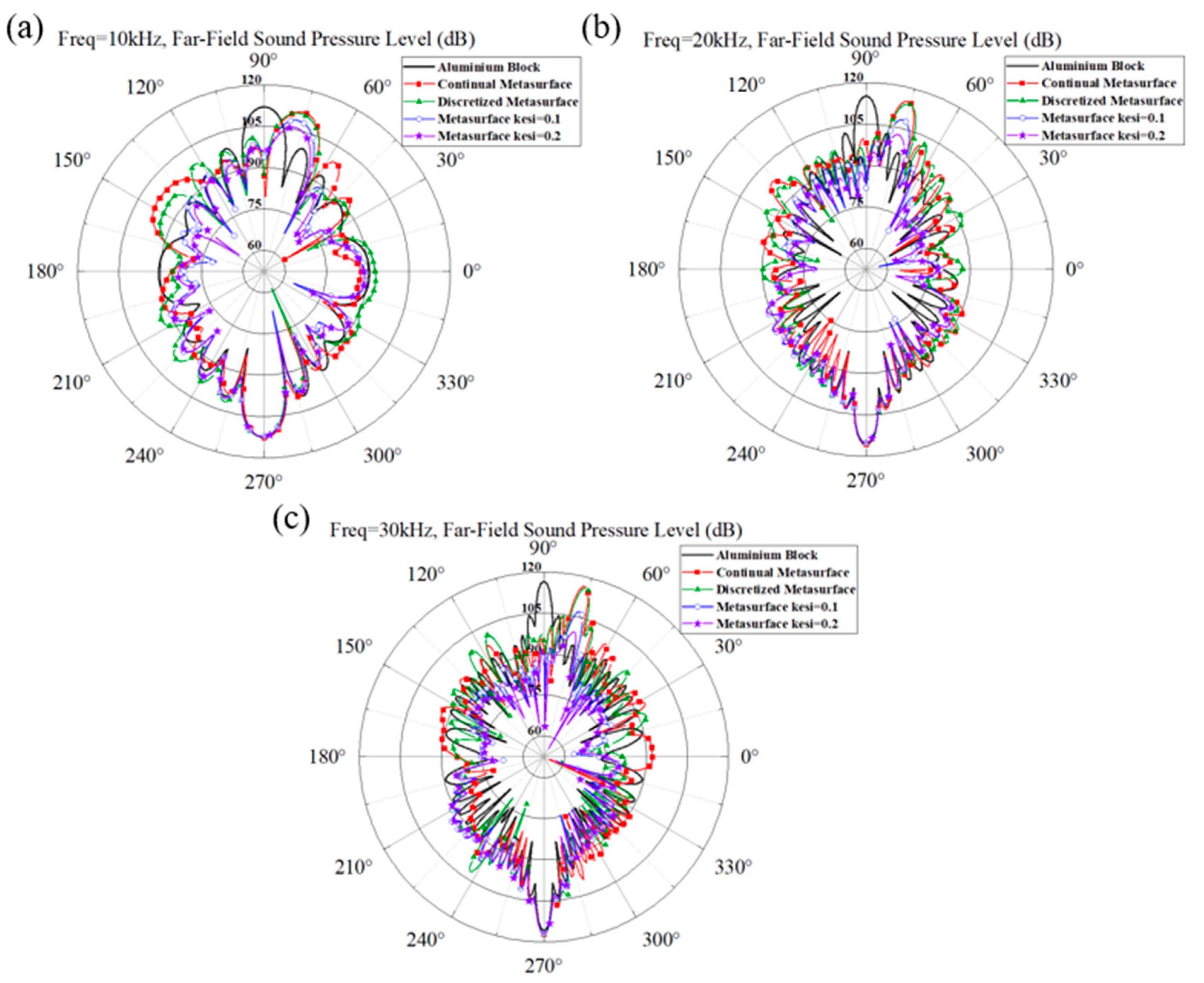
Figure 7.
The Far-Field Sound Pressure Level (FFSPL) of different frequencies for aluminum block and metasurface at the incident direction.
Figure 7.
The Far-Field Sound Pressure Level (FFSPL) of different frequencies for aluminum block and metasurface at the incident direction.
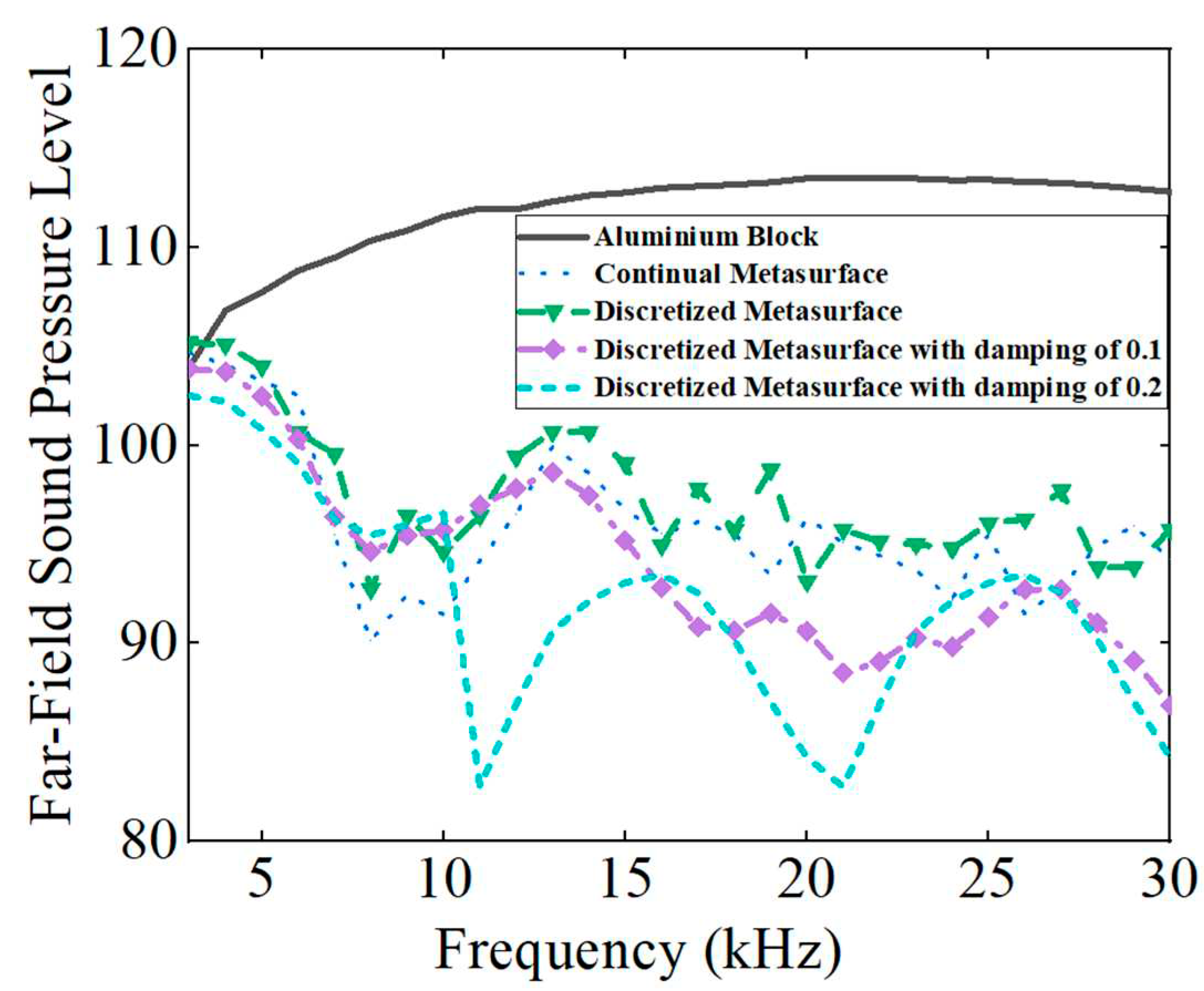
Figure 8.
The dispersion curves of four typical single-phase unit cells. (a)No.1, (b) No.5, (c)No.13, (d)No.20.
Figure 8.
The dispersion curves of four typical single-phase unit cells. (a)No.1, (b) No.5, (c)No.13, (d)No.20.
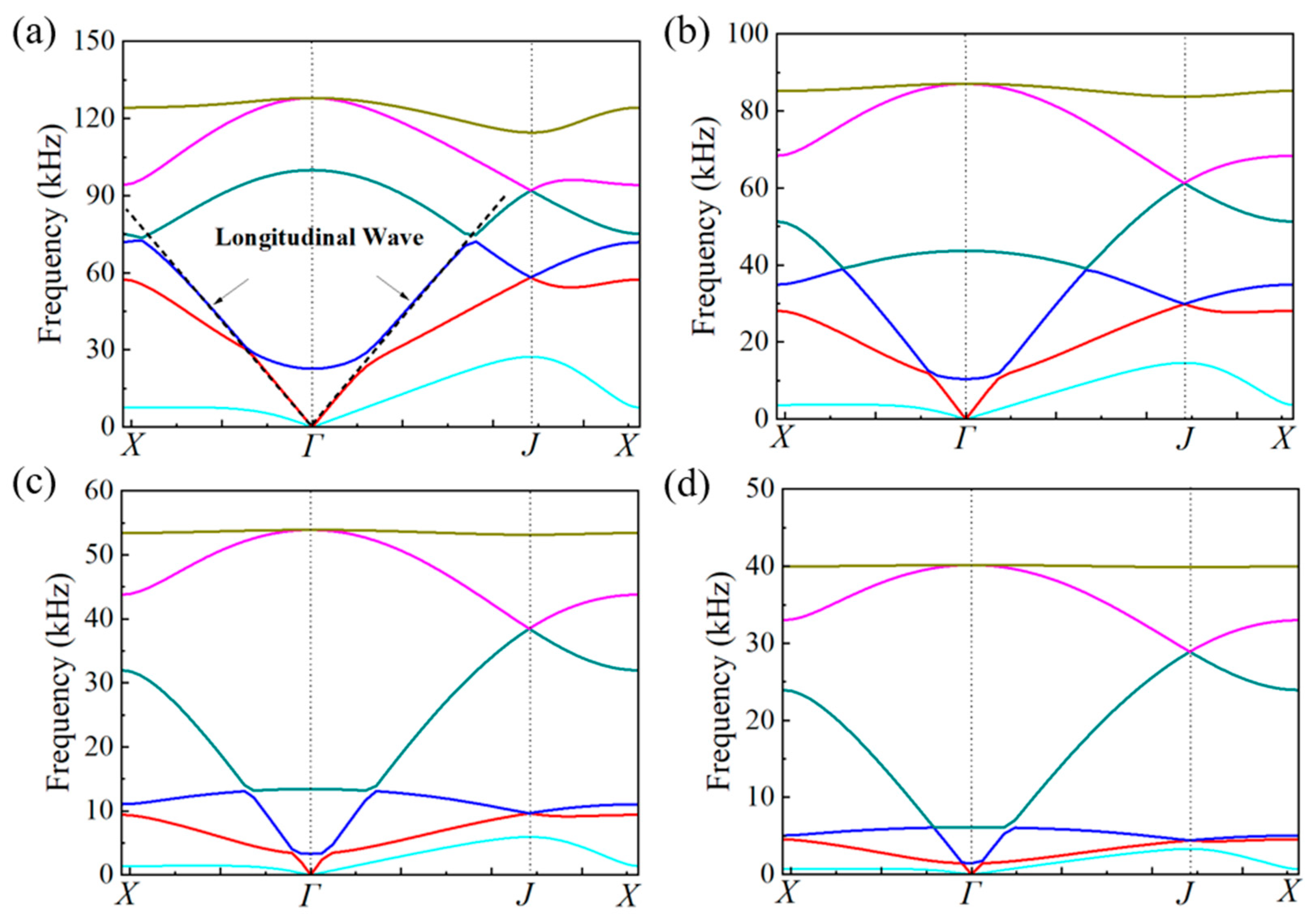
Figure 9.
The schematic picture of single-phase metasurface and gradual variation of the unit cells.
Figure 9.
The schematic picture of single-phase metasurface and gradual variation of the unit cells.
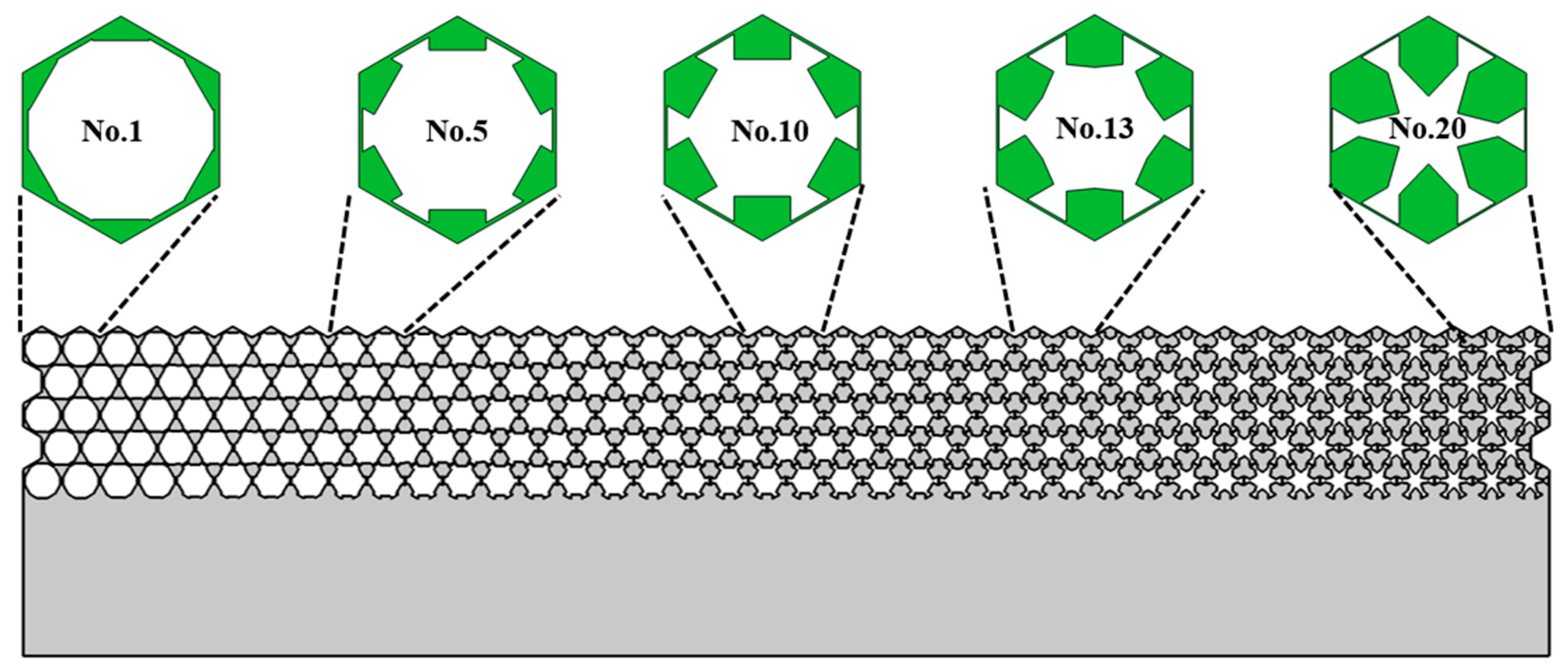
Figure 10.
The influence of damping coefficient on dispersion curves of unit cells. (a) and (b) correspond to the dispersion curve of No. 5 unit cell where a damping coefficient (0.2) of TPU substrate is considered in (b). (c) and (d) correspond to the dispersion curve of No. 16 unit cell where a damping coefficient (0.2) of TPU substrate is considered in (d).
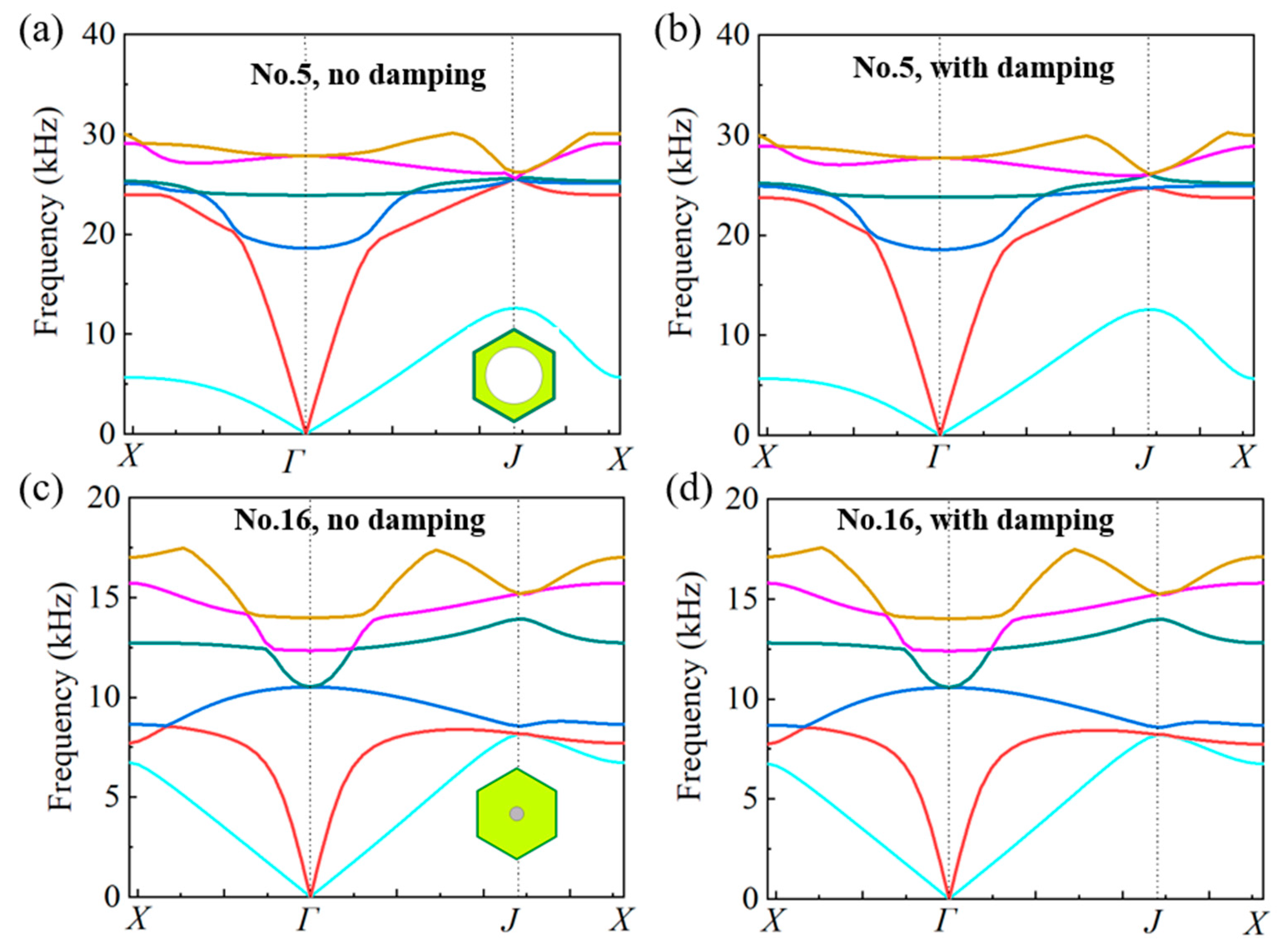
Figure 11.
The schematic picture of multiphase metasurface and gradual variation of the unit cells.
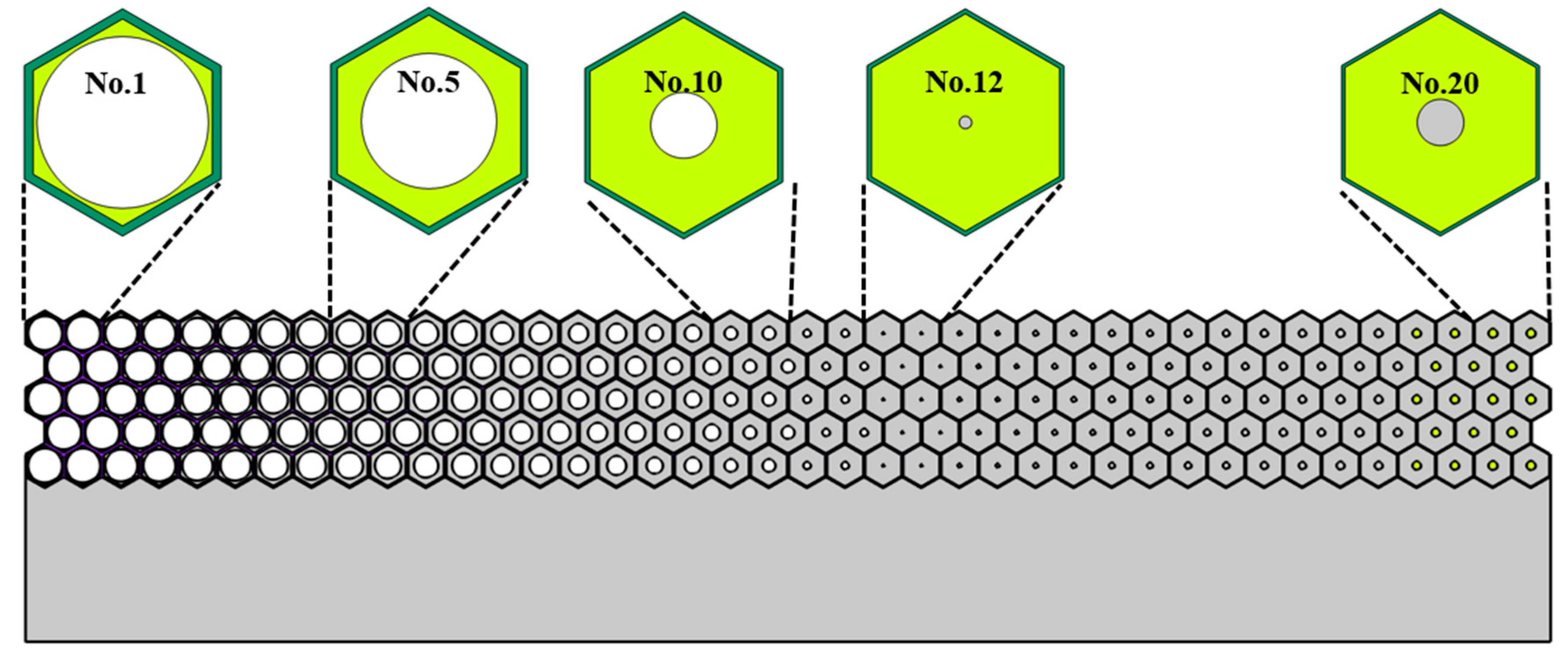
Figure 12.
The scattering acoustic pressure field map of the metasurface at 10kHz, 20kHz and 30 kHz. (a) ~ (c): Single-phase metasurface. (d) ~ (f): Multiphase metasurface without damping. (g) ~ (i): Multiphase metasurface with damping coefficient of 0.1. (j) ~ (l): Multiphase metasurface with damping coefficient of 0.2.
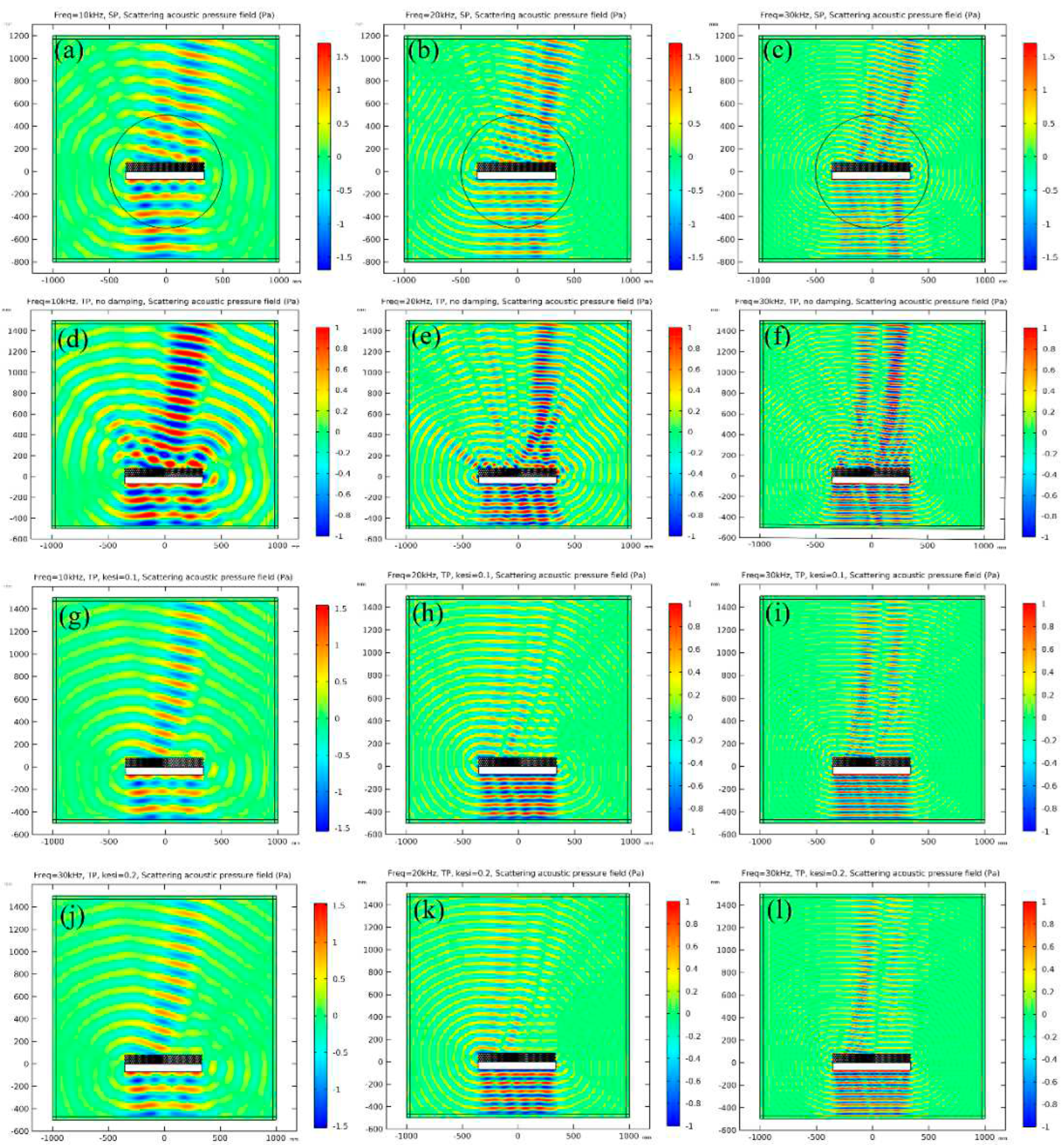
Figure 13.
The Far-Field Sound Pressure Level of different frequencies at the incident angle. (a) Comparison of FFSPL for single-phase metasurface with theoretical results. (b) Comparison of FFSPL for multiphase metasurface with theoretical results. (c) Comparison of FFSPL between multiphase metasurface and single-phase metasurface. (d) difference of multiphase metasurface and discretized metasurface with damping.
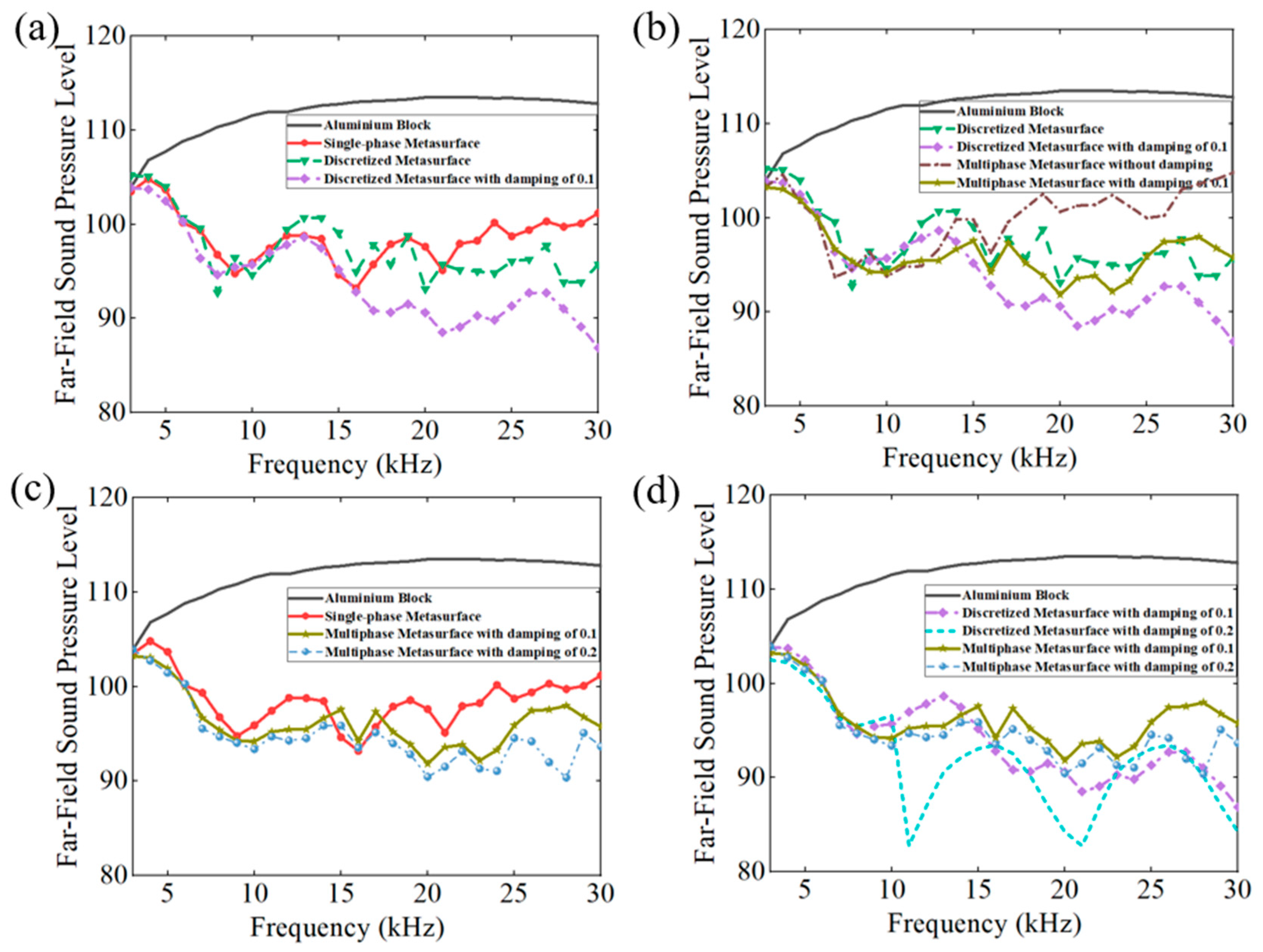
Figure 14.
The stress distribution of the proposed metasurface at a hydrostatic pressure of 5 MPa. (a) Single-phase metasurface. (b) Multiphase metasurface. (c) Enlargement for the most dangerous part of the latticed metasurface structure and compassion of the linearized mean stress (251 MPa for single-phase metasurface and 74.2 MPa for multiphase metasurface).
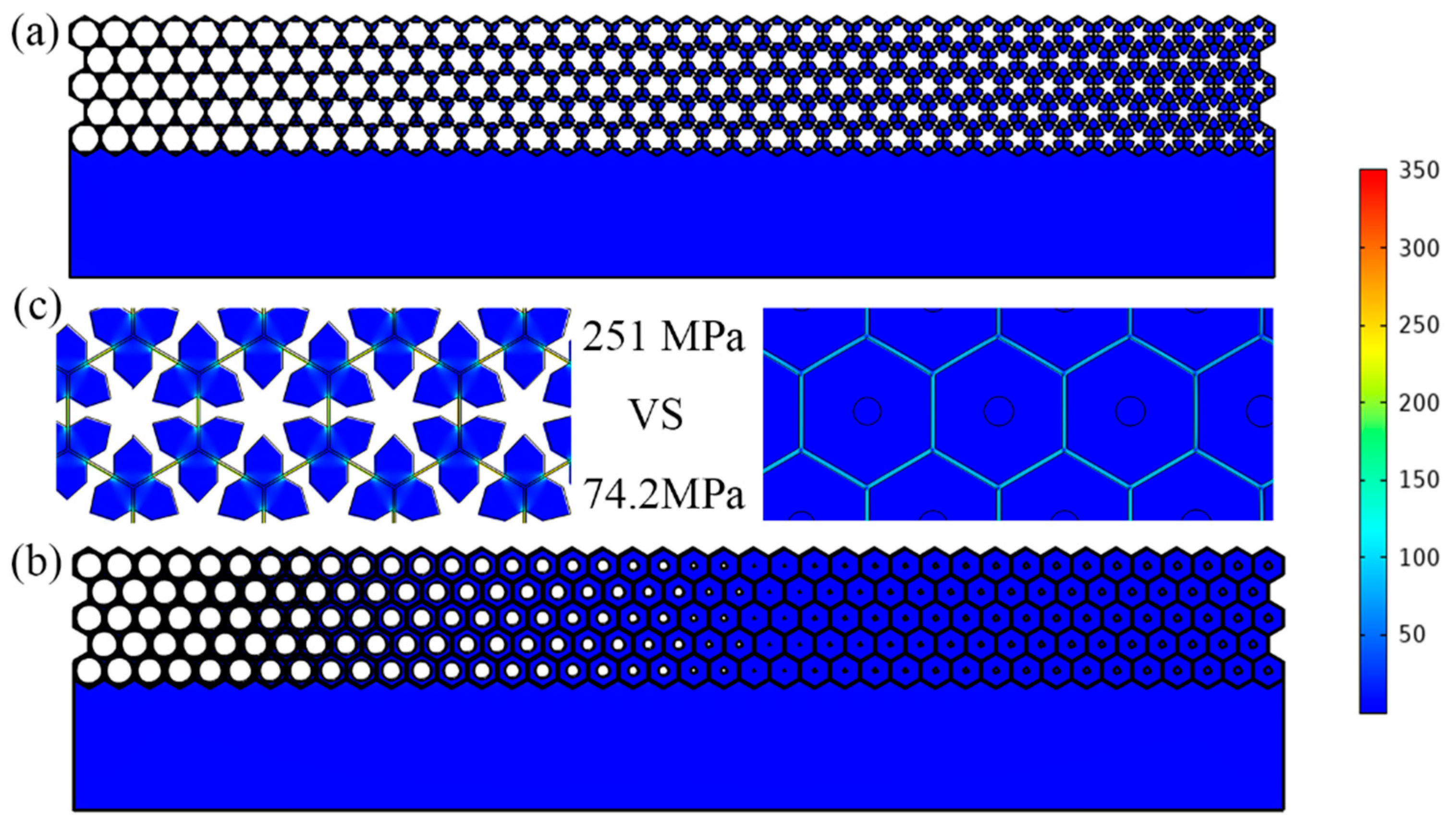

Table 1.
Equivalent properties of the discretized metasurface and corresponding microstructure parameters of the single-phase and multiphase configurations.
Table 1.
Equivalent properties of the discretized metasurface and corresponding microstructure parameters of the single-phase and multiphase configurations.
| Cell No. | Equivalent properties | Single-phase | Multiphase | ||||||
|---|---|---|---|---|---|---|---|---|---|
| X coordinate (m) | Density (ρ0) |
Modulus (κ0) |
t (mm) |
b(mm) |
m (mm) |
r (mm) |
t' (mm) |
R (mm) |
|
| 1 | -0.3291 | 0.5677 | 1.7616 | 1.000 | 2.5 | 0.13 | 0 | 1.55 | 7.75 |
| 2 | -0.2944 | 0.6237 | 1.6033 | 0.900 | 2.5 | 0.40 | 0 | 1.45 | 7.30 |
| 3 | -0.2598 | 0.6797 | 1.4711 | 0.820 | 2.5 | 0.66 | 0 | 1.35 | 6.90 |
| 4 | -0.2252 | 0.7358 | 1.3591 | 0.760 | 2.5 | 0.89 | 0 | 1.25 | 6.45 |
| 5 | -0.1905 | 0.7918 | 1.2629 | 0.680 | 2.5 | 1.15 | 0 | 1.17 | 5.95 |
| 6 | -0.1559 | 0.8478 | 1.1795 | 0.630 | 2.5 | 1.38 | 0 | 1.10 | 5.50 |
| 7 | -0.1212 | 0.9039 | 1.1063 | 0.545 | 2.5 | 1.64 | 0 | 1.03 | 4.90 |
| 8 | -0.0866 | 0.9599 | 1.0418 | 0.530 | 2.5 | 1.84 | 0 | 0.98 | 4.35 |
| 9 | -0.0520 | 1.0159 | 0.9843 | 0.515 | 2.5 | 2.03 | 0 | 0.93 | 3.70 |
| 10 | -0.0173 | 1.0720 | 0.9329 | 0.490 | 2.5 | 2.23 | 0 | 0.88 | 2.90 |
| 11 | 0.0173 | 1.1280 | 0.8865 | 0.465 | 2.5 | 2.44 | 0 | 0.82 | 1.70 |
| 12 | 0.0520 | 1.1841 | 0.8446 | 0.445 | 2.5 | 2.64 | 0 | 0.77 | 0.55 |
| 13 | 0.0866 | 1.2401 | 0.8064 | 0.425 | 2.5 | 2.70 | 0.27 | 0.74 | 0.90 |
| 14 | 0.1212 | 1.2961 | 0.7715 | 0.405 | 2.5 | 2.70 | 0.67 | 0.71 | 1.13 |
| 15 | 0.1559 | 1.3522 | 0.7396 | 0.380 | 2.5 | 2.70 | 1.08 | 0.68 | 1.33 |
| 16 | 0.1905 | 1.4082 | 0.7101 | 0.360 | 2.5 | 2.70 | 1.48 | 0.66 | 1.50 |
| 17 | 0.2252 | 1.4642 | 0.6830 | 0.350 | 2.5 | 2.70 | 1.85 | 0.64 | 1.65 |
| 18 | 0.2598 | 1.5203 | 0.6578 | 0.340 | 2.5 | 2.70 | 2.23 | 0.62 | 1.80 |
| 19 | 0.2944 | 1.5763 | 0.6344 | 0.330 | 2.5 | 2.70 | 2.62 | 0.60 | 1.92 |
| 20 | 0.3291 | 1.6323 | 0.6126 | 0.300 | 2.58 | 2.70 | 2.68 | 0.58 | 2.04 |
Disclaimer/Publisher’s Note: The statements, opinions and data contained in all publications are solely those of the individual author(s) and contributor(s) and not of MDPI and/or the editor(s). MDPI and/or the editor(s) disclaim responsibility for any injury to people or property resulting from any ideas, methods, instructions or products referred to in the content. |
© 2023 by the authors. Licensee MDPI, Basel, Switzerland. This article is an open access article distributed under the terms and conditions of the Creative Commons Attribution (CC BY) license (http://creativecommons.org/licenses/by/4.0/).
Copyright: This open access article is published under a Creative Commons CC BY 4.0 license, which permit the free download, distribution, and reuse, provided that the author and preprint are cited in any reuse.


