
Submitted:
25 June 2023
Posted:
25 June 2023
You are already at the latest version
Abstract
In this paper, a multirotor UAV platform based on the PX4 ecosystem was discussed, which in combination with the MATLAB Simulink programming environment enables utilization in various aspects of mechatronic engineering education. Extensive testing of the UAV platform control module was performed, in order to enable implementation in engineering education. In the design phase of the educational platform, take-off-the-shelf components were selected and tested, and airframe parts were manufactured using rapid prototyping technologies. The proposed educational platform with four rotors was presented and tested. The learning outcomes of the undergraduate mechatronics professional study program according to the Croatian Qualifications Framework and related to the considered platform are shown. A preliminary framework of laboratory exercises for the field of mechatronic systems control is investigated.
Keywords:
multirotor UAV
; engineering education
; Croatian Qualifications Framework
; PX4 ecosystem
; rapid prototyping
1. Introduction
Due to the increasing applications of unmanned systems in various fields, there is a real need for engineers who are able to, among others, control, plan, execute missions and maintain unmanned aerial vehicle (UAV) systems. A number of different UAV systems have been developed in recent years for numerous different applications [1-3]. Starting with the conventional fixed-wing models, well towards the development of Vertical Take-off and Landing (VTOL) UAVs. Generally, UAVs can be divided into fixed-wing aircraft, rotary-wing aircraft (or rotorcraft), hybrids, and flapping-wing aircraft. The rotary-wing aircraft can be further split into helicopters and multirotors. The main advantage of rotorcraft is the ability to perform a vertical and stationary flight, and motion at moderate speed, unlike fixed-wing aircraft, which, among other things, need a runway or ramp for launch. Fixed-wing aircraft use aerodynamic speed to produce the necessary lift force using streamlined lifting surfaces (wings). The rotary-wing aircraft, on the other hand, consist of spinning blades that produce lift force using their own power. The downside of the rotary-wing aircraft is the fact it has to produce all the necessary lift force with its power supply which can be energy inefficient thus impacting the flight endurance. Apart from having to lift its weight, it has to counteract the yawing moments by using the rotary blades in pairs. The downsides of the two are compensated with the use of hybrid UAVs which have the ability to vertically take-off using rotor blades and then proceed to use the fixed wings to generate lift force [4].
The fast development of micro-controllers, micro-electromechanical systems (MEMS), and batteries made it possible to develop multirotor UAVs. Within the rotorcraft category, multirotor UAVs stand apart from helicopters primarily due to their difference in the number and the dimensions of rotors. While helicopters use one or two main rotors for generating lift with the first one needing an additional tail stabilizing rotor, multirotor UAVs usually use pairs of rotors to generate lift force. The number of rotors and their arrangement depends upon the application of the UAV. They lack the flight endurance of a conventional fixed-wing aircraft but that is counterbalanced with the fast and precise flight positioning and maneuvering. A lot of research has been done in the multirotor UAV field and the possibilities of different configurations were investigated [5,6,7]. The performance of the multirotor UAV derives from the propulsion configuration, whereby by controlling the magnitude of the thrust force generated by the rotation of propellers it is possible to achieve motion in 3D space. Multirotor UAVs are characterized as nonlinear and inherently unstable systems, necessitating the implementation of stabilization techniques.
To fulfill this requirement, a variety of control and estimation methods are employed in research and product development [8,9,10,11,12]. Conventional control methods can be utilized such as Proportional–Integral–Derivative (PID) control or Linear Quadratic Regulator (LQR). This fact is of big importance from the education point of view, as it can be incorporated into the classroom. For instance, since PID control is already being studied in theory, at least as far as the professional studies of Mechatronics at Karlovac University of Applied Sciences, and at Zagreb University of Applied Sciences are concerned, its implementation becomes more accessible. Moreover, experiments can be conducted in laboratory conditions, particularly for smaller and lighter UAVs. In addition to existing commercial UAVs that are often used in research and education [13,14], there are numerous studies in which custom solutions are presented, primarily as quadrotors [15,16,17]. From the aspect of control design, in addition to simulations and experimental tests, it is important to consider the hardware in the loop (HITL) experiments, such as the HITL system based on Gazebo and Pixhawk flight controller (FC) [18]. Control methods are a part of the firmware which is run on the FC hardware. Open-source flight control software, including Dronecode (PX4) [19], Ardupilot [20], Paparazzi UAV [21], and others, offer versatility in selecting the appropriate flight control system for different applications. However, from the point of view of existing engineering education, these software options lack the ability to modify the flight control system or incorporate new models into the existing firmware without altering the source codeIn the context of engineering education and utilizing software, it becomes crucial to highlight the significance of an intuitive experimental framework within the existing tools used in the classroom.
In this paper, the application of multirotor UAVs in mechatronics education was investigated. From the aspect of mechatronics engineering professional study in Croatia, different learning outcomes are presented using the mathematical modeling, software aspects, and hardware aspects of the multirotor UAV. The PX4 system was chosen due to its easy implementation with the MATLAB Simulink software package. The proposed framework can be used to develop control systems for various multirotor UAV configurations (quadrotor, hexarotor, octorotor, etc.). Three experiments are presented, for three learning outcomes, as examples of multirotor integration into existing curriculum or for new courses. From the hardware aspects, the procedure of design and rapid prototyping of micro aerial vehicles (MAV) was briefly described. The prototype of the quadrotor UAV was tested indoors and outdoors. Based on the data, further improvements will be made to the educational UAV system.
2. Multirotor UAV System Description
In this section, the multirotor UAV system is briefly described and potential learning outcomes that can be directly connected to the UAV as an educational tool of the undergraduate mechatronics professional study program according to the Croatian Qualifications Framework (CQF) are given. One of the learning outcomes under the CQF is to identify, model and solve engineering problems (IUP6). The problem of inherent instability is typical for the multirotor type of UAV from the control point of view. If the functionality of the control loops is lost, the multirotor UAV cannot independently return to the state of balance (hovering), it starts to move uncontrollably and if the control loops are not restored, it will eventually fall to the surface of the earth. It follows that for the functioning of such a system, it is necessary to select the components and software solutions of the control system. To achieve this objective, it is essential to acquire a comprehensive understanding of the operational principles of such aircraft by identifying parameters and modeling the system.
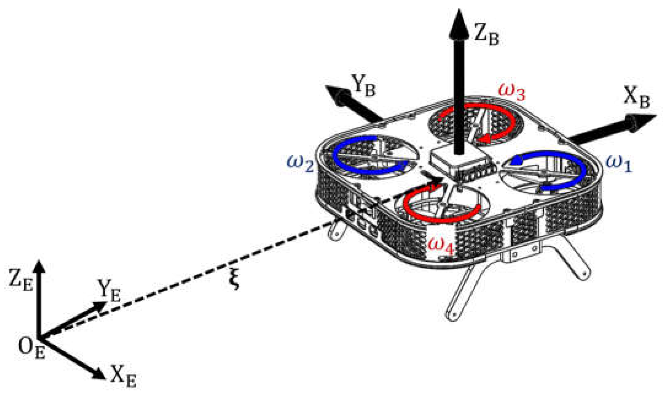
The state of the aircraft in real time is determined by its position and orientation in 3D space, which depends on the mission profile. The mathematical description of the UAV kinematics can be represented by the following expression
and is determined by the matrix , which, using fundamental rotation matrices (), maps the velocities from the aircraft body reference frame ( {}) which is shown in Figure1, to the velocities in the earth reference frame ( {}) from which the state of the aircraft is obtained . The kinematics of the unmanned aerial vehicle was obtained by applying certain laws and assumptions, which are directly related to the learning outcome, which is to apply mathematical and physical laws to engineering problems (IUP1).
Figure 1.
Quadrotor UAV reference coordinate systems.
From the aspect of further mathematical description, the multirotor represents a multivariable system that is described by a dynamic model of a rigid body with six second-order differential equations. The equations of motion can be derived using the Newton-Euler method assuming that the origin of the body frame coincides with the center of gravity, while the axes coincide with the principal axes of inertia of the UAV body. The equations of motion can be represented by the following expression
Parameters that provide resistance to the body motion are contained in matrix , where the translational dynamics are affected by the mass, and the rotational dynamics by the moments of inertia. Given that the UAV can freely rotate in 3D space, the Coriolis and centripetal matrix describes the inertial forces and moments. The body is acted upon by forces and moments resulting from the propulsion system and the environment acting on the UAV body.
Given that to achieve a stationary state, it is necessary to nullify the influence of the gravitational force , it follows from this fact that the mass of the multirotor UAV is a key parameter from the aspect of system design. The acceleration vector with respect to the body frame can be described by the following expression
where other unmodeled effects that affect the system dynamics, as well as external disturbances, are represented with vector d. To perform the mission, it is necessary to primarily select the parameters of the propulsion system, which are described from the dynamic aspect as forces and torques of the propulsion system with respect to the body frame. These vectors constitute the control vector , which can be given with the following expression
Propulsion system thrust forces vector and drag torques generated by the rotation of the propellers at each rotor are mapped to control vector through matrices () and () which represent propulsion configuration geometric arrangement, and are described in more detail in previous research [22].
Given that regarding planar configurations, the orientation vectors of each rotor are equal to unit vectors, therefore the size of the control vector is equal to four. In those cases, multirotor UAVs represent underactuated systems with coupled dynamics since the control vector size is less than the number of UAV DOFs. This applies to all planar configurations, regardless of the number of rotors, whether they are quadrotor, hexarotor, or octorotor UAVs. In addition, by selecting the parameters of the configuration’s geometric arrangement, it is possible to achieve fully-actuated multirotor UAVs such as configurations with passively tilted rotors [23], which can perform more complex and precise movements. The most commonly used, both in applications and research, is a configuration with four rotors, the so-called quadrotor (quadcopter). Assuming that the rotor thrust force () and drag torque ()can be simplified and modeled as a function of rotor angular velocity, where and are the thrust force and drag torque factors of i-th rotor, the control vector of the quadrotor with an X arrangement of rotors can be given by the following expression:
Once all the considered elements of the multirotor UAV mathematical model have been established, it is crucial to address the subsequent learning outcome, which involves utilizing the techniques, skills, and modern tools essential for engineering practice (IUP9) in the context of implementing the mathematical model within a software package. Taking into account its widespread application across various courses, as previously mentioned, the MATLAB Simulink software package is being considered, as it facilitates the execution of simulations as well as experiments, making it suitable for both classroom (auditory) and laboratory exercises.
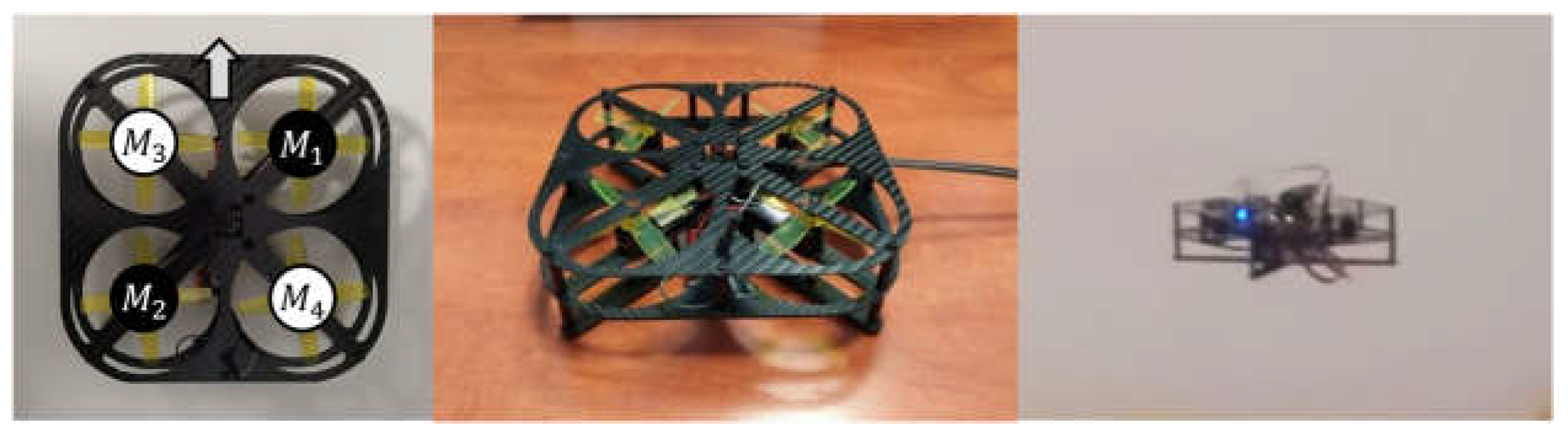
From the aspect of the physical model of the multirotor UAV, it is important to note several basic operations that should be followed. Before the first flight, it is mandatory to perform initial calibrations of the UAV system. Firstly, the propulsion system needs to be calibrated, after which, the control system, which comprises various sensors within the mandatory inertial measurement unit (IMU), must undergo a calibration process. Furthermore, configuration (airframe reference) and controller parameters need to be appropriately adjusted, failsafe mechanisms should be set, and additional modules such as RC control, GNSS, telemetry, and others must be configured. Calibration and first flight of the test quadrotor are illustrated in Figure 2, conducted as a preliminary phase prior to the actual research. The goal was to evaluate some system components such as the remote control module, to test the configuration of the MAV airframe, and to record flight data for subsequent analysis purposes. Here we come to another learning outcome, integrating a computer with software support in the process of data collection, measurement, and data display on a computer (IUP25), that is strongly related to multirotor UAV.
Figure 2.
Preliminary testing of platform hardware features.
3. Multirotor UAV Software Aspects
The potential control module hardware of the educational UAV is based on the Cube FC using the Dronecode PX4 autopilot. The key feature of that ecosystem from the education point of view is the open-source software architecture and compatibility with different modules, such as the radio receiver, GNSS, and telemetry. The radio receiver is needed to transmit commands using a remote controller, and it is selected depending on the requested channels, the type of communication, and the operating range. GNSS module is the main component for determining the position of the multirotor UAV during outdoor missions (flights). The telemetry components are used to transmit desired data to the ground control station, as well as change the firmware settings in real-time. The main advantage of the considered ecosystem is the possibility of integration with the MATLAB Simulink software package via the UAV Toolbox Support Package. This speeds up the process of developing software and hardware solutions for researchers in the field of aerial robotics. Furthermore, from the aspect of education, the integration of two learning outcomes is enabled, on the one hand, it is analyzing the behavior of mechatronic systems by modeling and simulating (IUP15), and from the aspect of laboratory exercises, programming, analyzing, simulating and demonstrating the operation of robots and planning trajectories (IUP23).
In this section, the main elements of the custom experimental firmware are presented and shown through typical experiments that can be implemented in the existing curriculum. The system is shown in block form in Figure 3, where the multirotor UAV represents the process, the filtering and estimation block is the feedback member and the control block consists of the algorithm and motor mixer. Such a schematic representation can be considered for several fundamental types of problems, performing simulations, software-in-the-loop testing, hardware-in-the-loop testing, and flight testing. Regarding the reference state, there are two fundamental cases concerning flight settings. In the case of autonomous flight, it is necessary to plan a mission where the UAV should move toward a predefined reference trajectory. In the case of remote control of the UAV, the pilot sets the reference state, i.e. directly controls the movement of the UAV. Setting the reference state, ie aircraft mission in the case of an autonomous flight is in the domain of path planning and depends on the aircraft configuration. In conventional configurations, the reference state consists mainly of a reference position in 3D space and a yaw angle. In fully actuated configurations, the reference state can be set for all six DOFs.
The status of the entire multirotor UAV system is logged to the SD card that is part of the FC which is highly recommended since a flight log is necessary to analyse flight details. From the aspect of monitoring the system state in real-time, the components of telemetry are used. They provide two-way communication, so in addition to receiving data on the aircraft position, energy consumption, and others, the system parameters can be adjusted in the base station (remote controller). In addition to telemetry, a set with a camera and video transmitter can be used to obtain a real-time image. Besides the remote control can be used to control the position and orientation of the aircraft, additional features can be used that control the entire system such as arming the aircraft, changing the flight mode, adjusting the controller parameters, and others. The functionality and modularity of the presented framework are demonstrated through three experiments. Testing was made possible by the development of experimental setups and UAVs.
3.1. Experiment 1—Design and Implementation of Complementary Filter
The first experiment that can be integrated through different courses in the considered professional study of mechatronics engineering, is related to the sensors block that represents the member of the feedback link. A set of sensors is in charge of measuring the state of the system. Among other quantities, the inputs to the sensors block are the measured values from the FC which has an integrated IMU consisting of an accelerometer, gyroscope, and also magnetometer, and barometer. The considered ecosystem based on Cube FC has double or triple redundancy of integrated sensors depending on the FC series. This data is used to determine the orientation and height of the multirotor UAV. Peripheral sensors are used to provide values that are used in order to determine other states, such as the position of the UAV, or from another perspective energy consumption during mission execution.
The case of estimating the orientation of the multirotor UAV was considered. The first step is to filter the signal coming from the IMU sensor. The modular design of the proposed firmware allows the implementation of custom filters and estimators, depending on the needs determined by the mission that the aircraft needs to perform. The implementation and testing of a complementary filter (CF) can be easily done, therefore it is suitable for educational purposes. In order to determine the multirotor attitude, a CF uses the accelerometer and gyroscope data as is schematically shown in Figure 4. In the conducted test Cube FC was oriented at nearly -45° and 45°, using a custom experimental test-bed with one DOF. A comparison between the CF and the built-in Extended Kalman Filter (EKF) in PX4 Autopilot has been shown. The presented experiment can be connected with the learning outcome of designing electronic devices with microcontrollers and creating microcontroller program solutions (IUP16).
3.2. Experiment 2—Gain Tuning of Cascaded PID Controller Based on the Ziegler-Nichols Method
Although the multirotor UAV’s flight dynamics are nonlinear, inherently unstable, and multivariable, there is an advantage in that positioning can be attained using conventional control methods. These controllers directly influence the four independent inputs, enabling easy stabilization of conventional multirotor configurations such as the quadrotor. Two more inputs can be controlled in case of fully actuated multirotors such as configurations with tilted rotors arms. The independent inputs are the forces and torques which are controlled by the angular velocities of the rotors. The Control Block contains the necessary control algorithm used to stabilize the multirotor where various types of algorithms can be implemented. From the aspect of education and creating microcontroller program solutions, it is important to emphasize the issue of multirotors in the sense that it is dangerous to test implemented program solutions if the parameters of the control system are not set. By means of an experimental setup that enables rotation around the y-axis (or x-axis) of the multirotor UAV, it is possible to test the control algorithm for one DOF in laboratory conditions. From the control aspect, simple integration of the multirotor UAV or its component parts with the setup can serve as an addition to existing experiments such as ball-on-beam for one DOF, and furthermore ball-on-plate for 2DOF [24] which are often used in engineering education.
The second experiment shows the use of a framework to demonstrate a multirotor UAV attitude control method for one DOF, which is referenced to the learning outcome calculate control parameters for the control of various technical processes (IUP18). Given that the PID controller is mostly used in practice, a cascade PID controller was also considered in the implementation phase. Through this experiment, attitude control is shown where the controller is implemented as part of the control block to stabilize the angle rates and the angles of the system. The experiment shows the Ziegler-Nichols method which can be used to tune the angle rate parameters of the inner PID control loop. Through the control block, it is possible to integrate online adjustment of the controller parameters using RC control, or telemetry. In the presented experiment, which is schematically shown in Figure 5., RC control is used in such a way that the parameters can be tuned online during the test (flight). Regarding this experiment, it is possible to easily and quickly adjust the parameters based on the Ziegler-Nichols method, which is performed in the following sequence: Increasing the proportional gain of the inner loop (rate) PID controller, oscillations are achieved, from which it is possible to read critical period . The critical proportional gain was then noted and the rest of the parameters were calculated using predefined coefficients.
3.3. Experiment 3—Control Block Implementation for Various Multirotor Configurations
The control block consists of a motor mixer block which incorporates scaling and a PWM limiter. Output PWM signals are sent to each of the propulsion units via the PX4 PWM Output Simulink block. The main function is a motor mixer block which depends upon the multirotor configuration parameters (geometric arrangement and propulsion characteristics). It can be said that the motor mixer block is used to allocate the control variables to the appropriate PWM signals to each propulsion unit for a given multirotor configuration. The control allocation matrix which was used as the base model used in this framework is presented in [16]. The control allocation scheme is implemented in the software package and serves as an offline tool for generating the motor mixer. Linearized PWM with respect to the aerodynamic effects is represented using parameters that are based on propulsion unit characteristics. The third experimental part consists of a series of experiments where the main goal is to verify the motor mixer for different multirotor UAV configurations. After the initial tuning was done on a system with one DOF, a test bed with three DOF (three rotations about body axes) was set up on which different configurations can be tested, as shown in Figure 6c. In order to show the multirotor UAV response, different references can be implemented within this framework.
Extensive testing of the UAV platform control module was performed, in order to enable implementation in engineering education. Several multirotor UAV configurations were tested, including conventional configurations with four, six, and eight rotors, and additionally a fully actuated configuration with passively tilted rotors. After conducting attitude control experiments, the multirotor configurations were tested for remote control in safety conditions within the laboratory and outdoors. The configuration with passively tilted rotors was tested for two remote control cases. In the first one, control inputs from the RC transmitter were thrust force and three moments (roll, pitch, and yaw), while in the second case, control inputs were three forces with respect to body axes, and yaw moment. In Figure 6, tests are shown for certain configurations where a cascade PID controller and a LQR were utilized.
4. Multirotor UAV Hardware Aspects
In the first stage of designing the educational platform, take-off-the-shelf components were selected and tested, and the production of the airframe parts is being considered by using rapid prototyping technologies. In general, multirotor UAVs can be divided into several essential subsystems that can be viewed as modules: control (avionics), propulsion, and energy module along with equipment and payload. With the intention of incorporating the multirotor UAV into engineering education, the control module components assume paramount importance. In this regard, the PX4 ecosystem emerges as an optimal platform for engineering education due to its seamless integration with the MATLAB programming environment, as mentioned earlier. Of particular significance is the FC, and for this research, the Cube Black and the Cube Purple with their respective carrier boards were utilized as central components.
The Cube series of FC enables the connection of various peripheral modules and sensors such as GNSS and telemetry. Furthermore, two types of remote control subsystems were analyzed and used in this research. The first type operates on a standard frequency (2.4 GHz), employing the X8R receiver capable of accessing all 16 channels via the SBUS RC protocol, and the Taranis X9s and X7s, remote control transmitters are utilized. The second type consists of Crossfire receivers that operate at a lower frequency (868 MHz) also using the SBUS RC protocol. In this setup, a TX16S transmitter is used in combination with a Crossfire long-range R/C link. The FC carrier board supplies peripheral components and sensors, and it is supplied via a power brick with a sensor that is connected between the batteries and the propulsion components and it provides a stable 5V voltage. It is used for consumption up to 60A at 2S, 3S, and 4S voltage setups. The selection of multirotor UAV system components is a challenging problem and can be considered through the following learning outcome: Select and connect sensors, actuators, microcomputers, programmable logic controllers, and related equipment for automation of production processes (IUP21).
The propulsion components are responsible for the generation of the necessary aerodynamic forces and torques. With regard to educational needs, multirotor UAVs with a diameter (diagonal) of up to 0.3 m have been taken into account, which can be used in indoor experiments. To propel an electric multirotor UAV, electric propulsion units (EPUs) are employed, which comprise a Brushless DC (BLDC) electric motor, an Electronic Speed Controller (ESC), and a fixed-pitch propeller mounted on a motor rotor. The propulsion components of the multirotor UAV are also related to the following learning outcome: Knowing the working principles of electronic and electromechanical converters (IUP14). BLDC motor is a permanent magnet electric motor where electromagnets (armature) are located on the stator of the motor while permanent magnets are located on the rotor which is positioned outside the stator, the so-called outrunner motor. The motor is driven by a rectangular shape input voltage (six-step commutation) provided by an ESC that converts the supplied DC voltage into appropriate motor phase voltages. The desired RPM is established by the input PWM signal originating from the FC.
In terms of the engineering education platform’s size, it utilizes small BLDC motors with a higher velocity constant (Kv > 2000) in combination with propellers ranging from 2 to 7 inches, and batteries comprising 3 to 6 cells. It is important to emphasize that this type of UAV is a system of high energy consumption considering that rotary wings must cancel gravity force. To power all the mentioned modules an energy module typically consists of one or more LiPo batteries with all the necessary wiring and connectors to other subsystems. The overall performance depends on the capacity and mass of the battery. The recommended propulsion setups are given by the manufacturer in the form of tabular specifications from which characteristics can be obtained as shown in Figure 7.
4.1. Multirotor UAV Prototyping Phase
The design of the multirotor UAV assembly is interesting from the aspect of the following learning outcome: Create 2D technical documentation and construct a 3D model of mechatronic systems (IUP17). Different CAD software packages can be used for modeling airframe parts, whereas the SOLIDWORKS software package was used in this research. From the aspect of the production of adaptable educational (training) UAVs, it is important to emphasize several features. First of all, attention should be paid to safety with regard to the characteristics of this type of UAV, given that is intended to be extensively tested in laboratory exercises. Furthermore, it is convenient to use rapid prototyping (RP) technologies—which speed up the manufacturing process and enables the replacement, modification, and improvements of airframe parts in-house. The next objective in the design phase is to attain simple integration with setups that involve independent testing for individual DOFs or groups of DOFs during different testing phases, such as attitude control experiments. In the phase of airframe parts prototyping, two categories of RP technologies were considered. Figure 8 shows a 3D model of the experimental educational quadrotor assembly. The prototype consists of a T-Motor F1408 BLDC motor with velocity constant Kv=3950 on which HQprop T3X2.5X3 propellers are mounted.
A 3-axis CNC router with a milling motor is used to produce airframe parts from carbon sheets of various thicknesses. With the hardware used, the procedure is relatively simple, where it is important to choose tools and cutting parameters. Multirotors offer an engineering perspective, regarding airframe construction which can be related to the following learning outcome: to construct assemblies in accordance with the laws of strength and deformation of materials, kinematics, and dynamics (IUP13). Moreover, additive manufacturing (AM) technologies were employed for airframe parts production. To manufacture components that are subjected to lower mechanical loads, the fused deposition modeling (FDM) technology using the Prusa i3 MK3 3D printer is being utilized. On the other hand, the continuous fiber fabrication (CFF) technology, alongside the Markforged Onyx Pro 3D printer, is being employed for airframe parts subjected to higher mechanical loads. In this case, CFF technology employs a nylon matrix material filled with micro carbon fibers (Onyx) and fiberglass reinforcement material. Additional features of the considered assembly are the possibility of a plug-in for the battery and a simple replacement of the Cube FC series (purple, black, red). In the assembly phase, several preliminary tests were performed, such as testing the direction of rotation of the propulsion motors (Figure 9 a), first flights and testing of the supporting airframe (Figure 9 b), and calibration of the educational prototype assembly (Figure 9 c).
4.2. Educational Multirotor UAV Experimental Framework
The presented hardware solution is integrated with the MATLAB eco system in order to conduct experiments regarding various aspects of the multirotor UAV. After the successful integration, assembly, and preliminary testing of individual subsystems, calibration, and preliminary tests were carried out in the case of the remote control. The preliminary outdoor flights were carried out on the training ground surrounded by a protective net, as shown in Figure 10. It is important to emphasize a few things related to outdoor flight. Testing can be performed independently in facilities such as large-volume cages, and if there is no facility, then it is necessary to obtain permits from regulatory bodies, which is not appropriate from the education point of view, especially since system outages are possible during experiments. Considering the characteristics of the multirotor UAV, from the education point of view, this shortcoming can be overcome by indoor testing where minor modifications of the space are required to ensure safety.
Furthermore, an experimental framework for indoor testing is considered, which is appropriate because it continues to attitude control experiments conducted using experimental setups. In general, the flight (experiment) data is logged on the SD card and can be further analyzed. In MATLAB software, a script was executed that reads data from the SD card, save data, and plot graphs. Regardless of the missions, from the aspect of system control, the presented attitude experiments can be taught in designing the multirotor UAV control. In the case of indoor testing of the multirotor position control, from the aspect of state estimation, sensors can be categorized into two main types: onboard sensors and external sensors. Regarding onboard sensors, besides sensors incorporated in FC, and energy module, other sensors are used for state estimation such as optic flow, and IR Lock. Motion capture systems serve as external sensors that facilitate precise pose and orientation data, enabling simultaneous tracking of multiple objects. This capability proves especially valuable for testing multirotor UAVs. Moreover, these systems find extensive application across various domains and are desirable in modern research and educational laboratories. In the coming period, extensive testing will be done in the laboratory using the OptiTrack system, which consists of 6—12 Primex cameras [25].
5. Discussion
In this paper, the multirotor type of UAV is presented through the view of engineering education. The paper summarizes the learning outcomes related to multirotor UAVs from the mathematical model, software, and hardware aspects. In addition, multirotor UAVs can be considered through additional learning outcomes, such as adapting to work in project teams (IUP5), and outcome: critically evaluate professional facts, terms, procedures, principles, and theories in the field of mechatronics. In Table 1 the learning outcomes of the undergraduate mechatronics professional study program according to the CQF and related to the considered multirotor UAV platforms are shown. The number is impressive (14/27), even though UAV experts did not necessarily participate in the creation of the curriculum, so it is not biased.
From the software aspect, the focus of the work is in the area of control design, although the overall solution enables elaborations in other areas as well. Three proposals for experimental cases are presented, which can serve as a basis for the preparation of laboratory exercises. In further work, the integration and testing of the Optitrack motion capture system and the prototyping of the next experimental platform are planned in terms of software and hardware development. Most importantly, however, the validated experiments will be elaborated in detail and implemented in classes at the mechatronics professional study at the Karlovac University of Applied Sciences, and Zagreb University of Applied Sciences. An educational multirotor experimental testing framework is designed for students to gain hands-on experience in the field of UAVs and control design. By working with the platform, students can apply theoretical concepts learned in the classroom to real-world scenarios, and gain practical skills that are highly valued in the industry.
Author Contributions
Conceptualization, D.K. and P.P.; software, M.P. and D.K.; validation, P.P. and T.B.; data curation, M.P.; writing—original draft preparation, D.K.; writing—review and editing, P.P.; visualization, M.P.; supervision, T.B. All authors have read and agreed to the published version of the manuscript.
Funding
This research was funded by European Regional Development Fund, Operational programme competitiveness and cohesion 2014–2020, grant number KK.01.1.1.04.0092 and the APC was funded by KK.01.1.1.04.0092.
Acknowledgments
This research was funded by European Regional Development Fund, Operational programme competitiveness and cohesion 2014–2020, grant number KK.01.1.1.04.0092.
Conflicts of Interest
The authors declare no conflict of interest.
References
- A Dronova, I.; Kislik, C.; Dinh, Z.; Kelly, M. A Review of Unoccupied Aerial Vehicle Use in Wetland Applications: Emerging Opportunities in Approach, Technology, and Data. Drones. 2021, 5, 45. [Google Scholar] [CrossRef]
- Islam, N.; Rashid, M.M.; Pasandideh, F.; Ray, B.; Moore, S.; Kadel, R. A Review of Applications and Communication Technologies for Internet of Things (IoT) and Unmanned Aerial Vehicle (UAV) Based Sustainable Smart Farming. Sustainability. 2021, 13, 1821. [Google Scholar] [CrossRef]
- Park, S.; Choi, Y. Applications of Unmanned Aerial Vehicles in Mining from Exploration to Reclamation: A Review. Minerals. 2020, 10, 663. [Google Scholar] [CrossRef]
- Kaparos, P.E.; Bliamis, C.D.; Yakinthos, K. Conceptual design of a UAV with VTOL characteristics. AIAA Aviation 2019 Forum, June 17-21, 2019., Dallas, TX, USA. [CrossRef]
- Xia, D.; Cheng, L.; Yao, Y. A Robust Inner and Outer Loop Control Method for Trajectory Tracking of a Quadrotor. Sensors. 2017, 17, 2147. [Google Scholar] [CrossRef] [PubMed]
- Park, J.; Cho, N. Collision avoidance of hexacopter UAV based on LiDAR data in dynamic environment. Remote Sens. 2020, 12, 975. [Google Scholar] [CrossRef]
- Ikeda, T.; Yasui, S.; Fujihara, M.; Ohara, K.; Ashizawa, S.; Ichikawa, A.; Okino, A.; Oomichi, T.; Fukuda, T. Wall contact by octo-rotor UAV with one DoF manipulator for bridge inspection. In Proceedings of the 2017 IEEE/RSJ International Conference on Intelligent Robots and Systems (IROS), Vancouver, BC, Canada, 24–28 September 2017; pp. 5122–5127. [Google Scholar] [CrossRef]
- Franklin, G.F.; Powell, J.D.; Emami-Naeini, A.; Powell, J.D. Feedback control of dynamic systems. Pearson: New Jersey, 2002. [Google Scholar]
- Bouabdallah, S.; Noth, A.; Siegwart, R. PID vs LQ control techniques applied to an indoor micro quadrotor. In Proceedings of the 2004 IEEE/RSJ International Conference on Intelligent Robots and Systems (IROS), Sendai, Japan, 28 September–2 October 2004; pp. 2451–2456. [Google Scholar] [CrossRef]
- Kasac, J.; Stevanovic, S.; Zilic, T.; Stepanic, J. Robust output tracking control of a quadrotor in the presence of external disturbances. Trans. FAMENA 2013, 37, 29–42. [Google Scholar]
- Pranjic, M.; Pender, A.; Piljek, P.; Kotarski, D. Fully Actuated Multirotor UAV Control Design and Implementation. 2022 International Conference on Electrical, Computer and Energy Technologies (ICECET), Prague, Czech Republic, 2022, pp. 1-6. [CrossRef]
- Kasac, J; Pender, A; Pranjic, M; Kotarski, D. Frequency-shifting-based algebraic approach to extended state observer design. Asian J Control. 2021; 23: 2171– 2184. [CrossRef]
- Krajník, T.; Vonásek, V.; Fišer, D.; Faigl, J. AR-drone as a platform for robotic research and education. In Research and Education in Robotics—EUROBOT 2011, Proceedings of the EUROBOT: International Conference on Research and Education in Robotics, Prague, Czech Republic, 15–17 June 2011; Obdržálek, D., Gottscheber, A., Eds.; Springer: Berlin/Heidelberg, Germany, 2011; Volume 161, pp. 172–186. [Google Scholar] [CrossRef]
- Giernacki, W.; Skwierczyński, M.; Witwicki, W.; Wroński, P.; Kozierski, P. Crazyflie 2.0 quadrotor as a platform for research and education in robotics and control engineering. Proceedings of the 22nd International Conference on Methods and Models in Automation and Robotics (MMAR 2017), Miedzyzdroje, Poland, 28-31 August 2017; IEEE; 37-42. [CrossRef]
- Jin, J.; Jo, J.H. A test bench with six degrees of freedom of motion for development of small quadrotor drones. J. Aerosp. System Eng. 2017, 11, 41–46. [Google Scholar] [CrossRef]
- Santos, M.F.; Silva, M.F.; Vidal, V.F.; Honório, L.M.; Lopes, V.L.M.; Silva, L.A.Z.; Rezende, H.B.; Ribeiro, J.M.S.; Cerqueira, A.S.; Pancoti, A.A.N.; Regina, B.A. Experimental validation of quadrotors angular stability in a gyroscopic test bench. Proceedings of the 2018 22nd International Conference on System Theory, Control and Computing (ICSTCC), Sinaia, Romania, 10–12 October 2018; IEEE; 600–605. [CrossRef]
- Waliszkiewicz, M.; Wojtowicz, K.; Rochala, Z.; Balestrieri, E. The Design and Implementation of a Custom Platform for the Experimental Tuning of a Quadcopter Controller. Sensors 2020, 20, 1940. [Google Scholar] [CrossRef] [PubMed]
- Nguyen, K.D.; Ha, C. Development of Hardware-in-the-Loop Simulation Based on Gazebo and Pixhawk for Unmanned Aerial Vehicles. Int. J. Aeronaut. Space Sci. 2018, 19, 238–249. [Google Scholar] [CrossRef]
- Dronecode PX4. Available online: https://docs.px4.io/main/en/ (accessed on 20 June 2023).
- Hentati, A.I.; Krichen, L.; Fourati, M.; Fourati, L.C. Simulation Tools, Environments and Frameworks for UAV Systems Performance Analysis. International Wireless Communications Mobile Computing Conference (IWCMC), June 25-29, 2018., Limassol. [CrossRef]
- Gati, B. Open source autopilot for academic research—The Paparazzi system. American Control Conference (ACC), June 17-19, 2013., Washington. [CrossRef]
- Piljek, P.; Kotarski, D.; Krznar, M. Method for Characterization of a Multirotor UAV Electric Propulsion System. Appl. Sci. 2020, 10, 8229. [Google Scholar] [CrossRef]
- Kotarski, D.; Piljek, P.; Kasać, J.; Majetić, D. Performance Analysis of Fully Actuated Multirotor Unmanned Aerial Vehicle Configurations with Passively Tilted Rotors. Appl. Sci. 2021, 11, 8786. [Google Scholar] [CrossRef]
- Kopichev, M.M.; Putov, A.V.; Pashenko, A.N. Ball on the plate balancing control system. IOP Conf. Ser.: Mater. Sci. Eng. 2019, 638, 1–6. [Google Scholar] [CrossRef]
- Optitrack Primex 22 Specs. Available online: https://optitrack.com/cameras/primex-22/specs.html (accessed on 21 June 2023).
- Program preddiplomskog stručnog studija Mehatronika usklađen s HKO registrom i kvalifikacijom stručni/a prvostupnik/prvostupnica (baccalaureus/baccalaurea) inženjer/inženjerka mehatronike. Available online: https://vub.hr/hko-mehatronika/doc/e1/Program%20preddiplomskog%20stru%C4%8Dnog%20studija%20Mehatronika.pdf (accessed on 23 June 2023).
Figure 3.
Multirotor UAV control scheme block diagram.
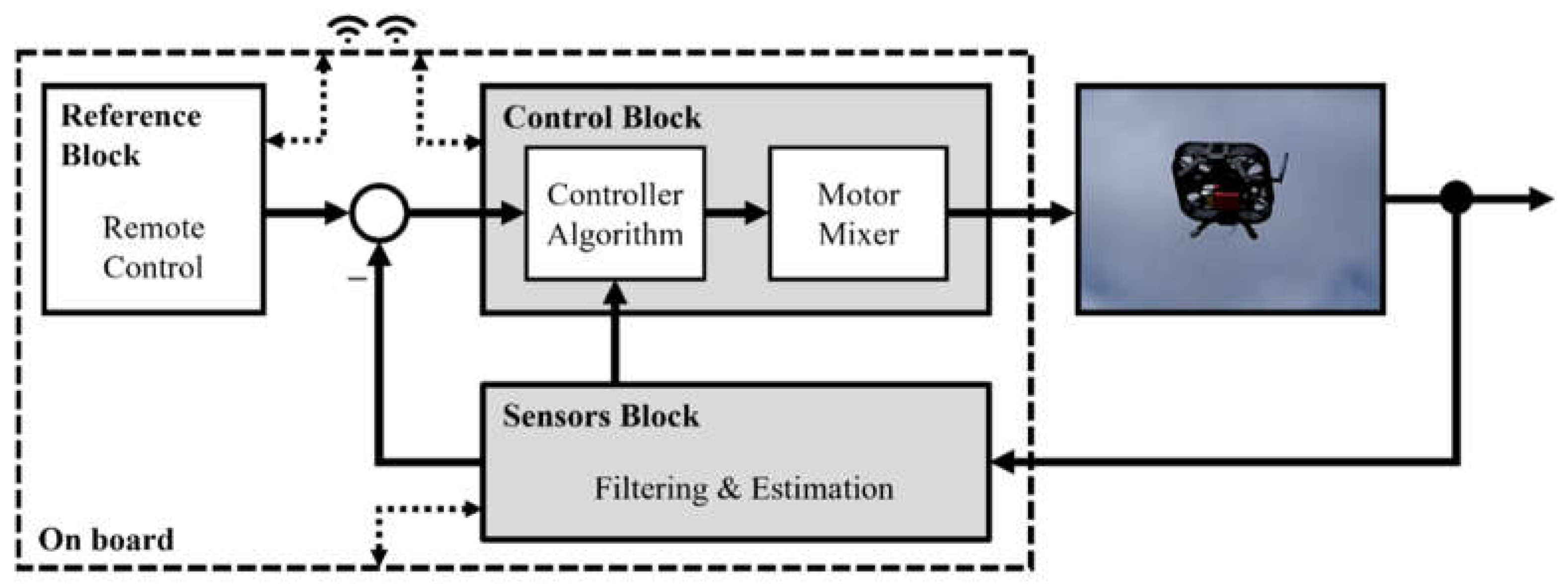
Figure 4.
Schematic representation of experiment 1.
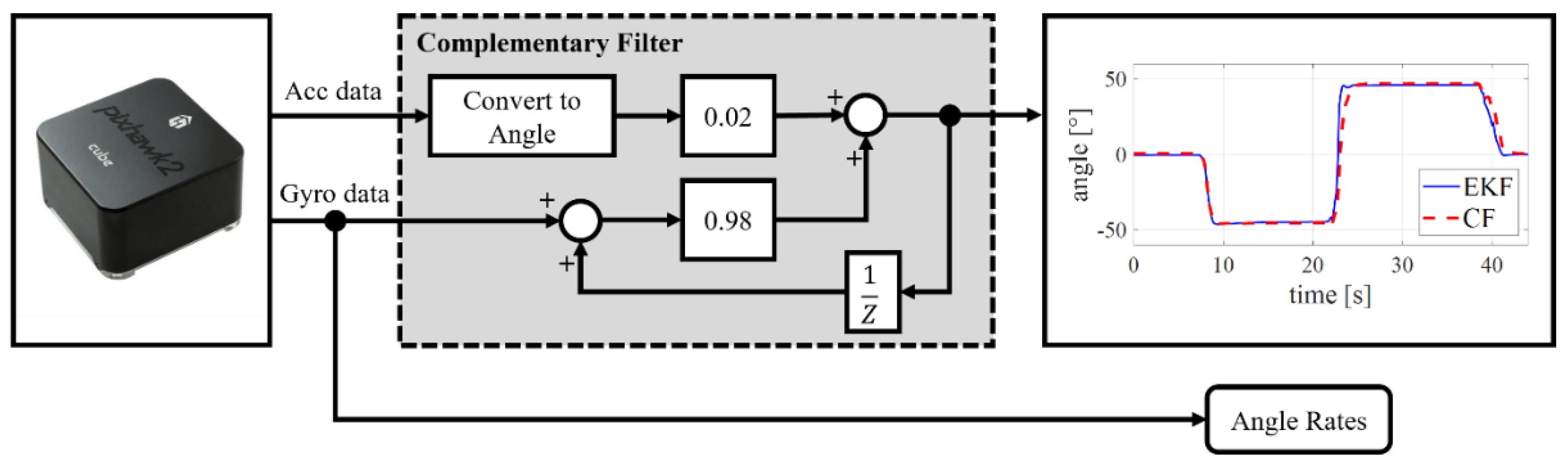
Figure 5.
Schematic representation of experiment 2.
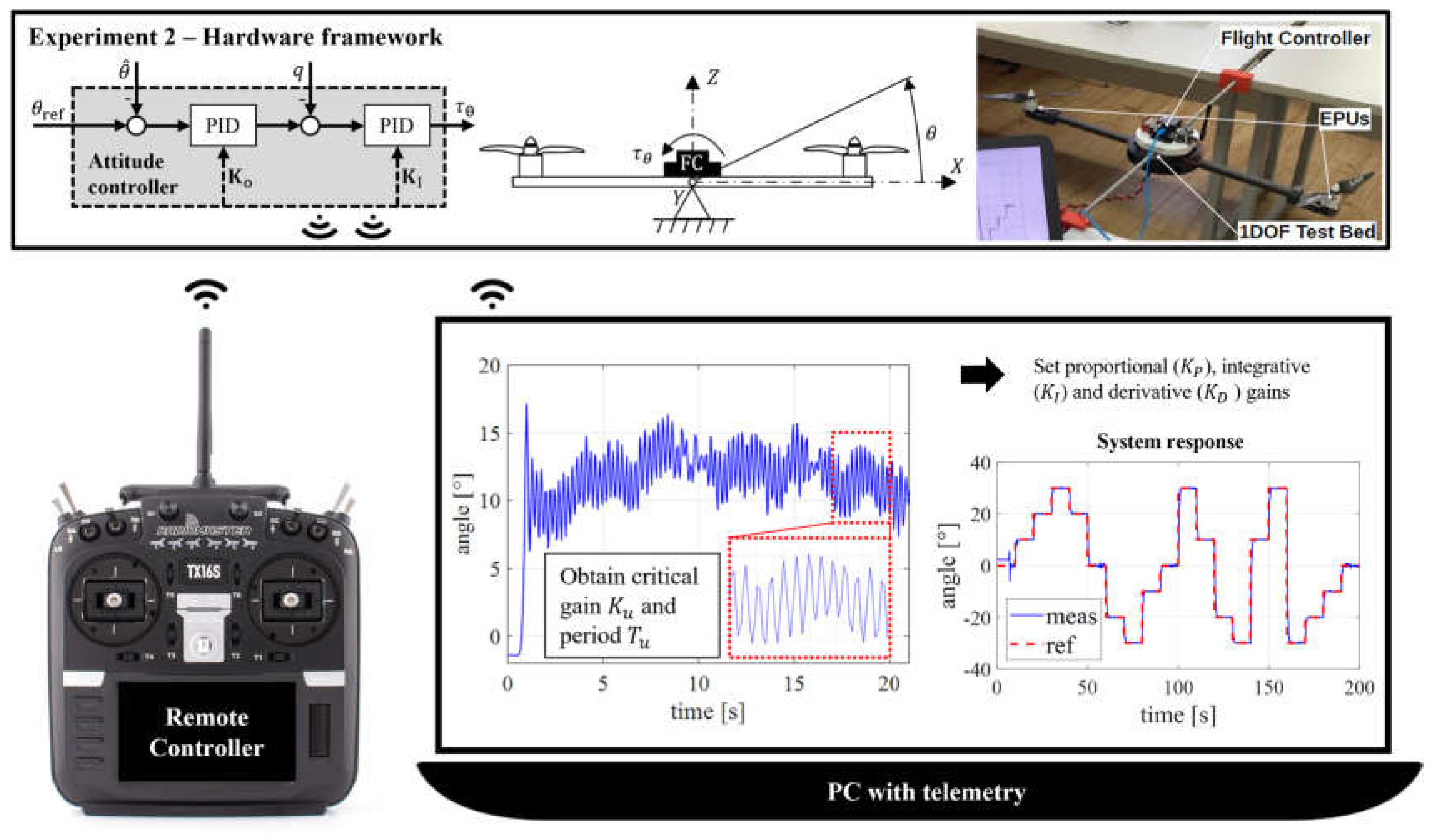
Figure 6.
Motor mixer verification experiment: (a) Quadrotor; (b) Ocotorotor; (c) Fully actuated hexarotor.
Figure 6.
Motor mixer verification experiment: (a) Quadrotor; (b) Ocotorotor; (c) Fully actuated hexarotor.
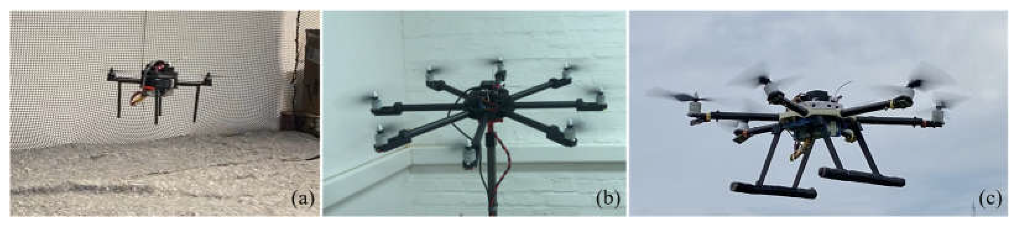
Figure 7.
Characteristics of considered electric propulsion unit setups.
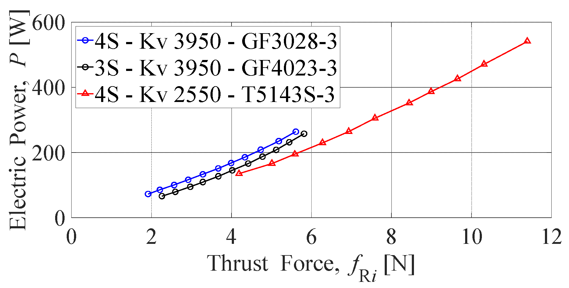
Figure 8.
Experimental educational quadrotor—3D model assembly.
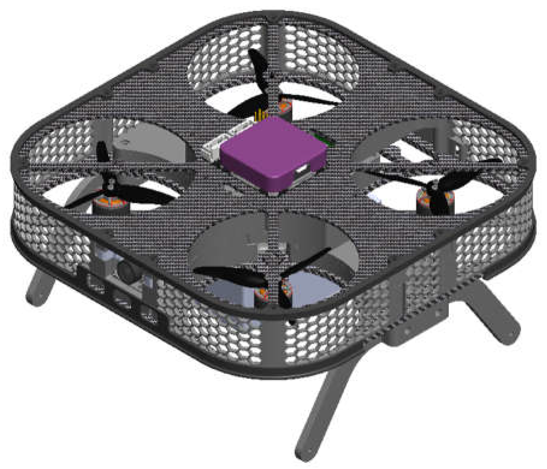
Figure 9.
Phases of assembling the quadrotor UAV: (a) Testing the propulsion elements using a servo tester; (b) Preliminary testing of the supporting airframe; (c) Ready-to-fly experimental platform.
Figure 9.
Phases of assembling the quadrotor UAV: (a) Testing the propulsion elements using a servo tester; (b) Preliminary testing of the supporting airframe; (c) Ready-to-fly experimental platform.
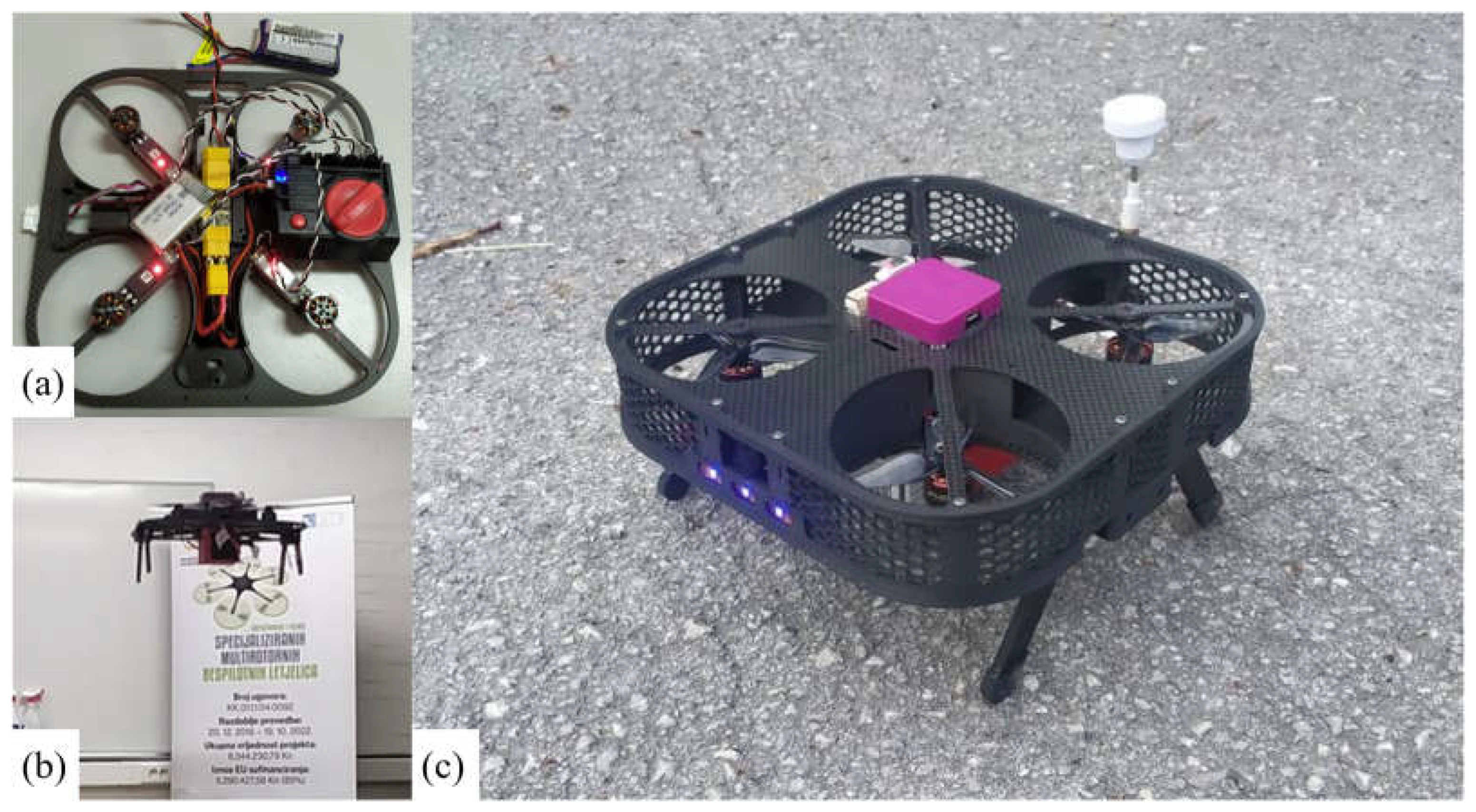
Figure 10.
Preliminary outdoor experimental testing: (a) Quadrotor platform during the experiment; (b) Plotted graph of battery voltage.
Figure 10.
Preliminary outdoor experimental testing: (a) Quadrotor platform during the experiment; (b) Plotted graph of battery voltage.
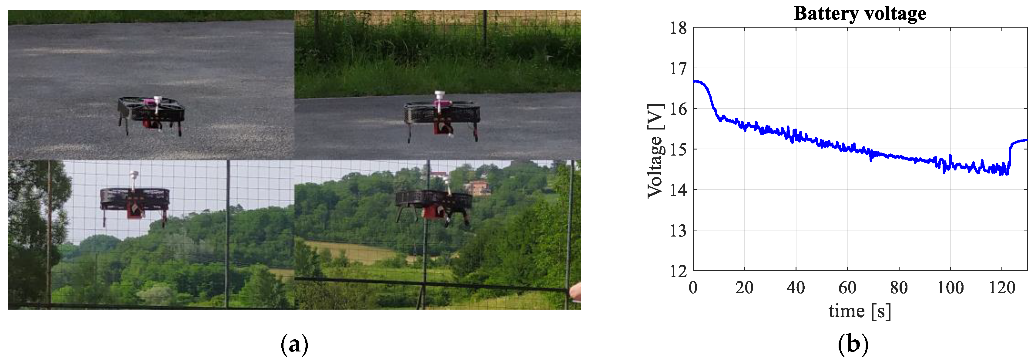

Table 1.
Learning outcomes of the undergraduate professional mechatronics study program according to CQF [26].
Table 1.
Learning outcomes of the undergraduate professional mechatronics study program according to CQF [26].
| Program learning outcome code | Learning Outcomes of the Undergraduate professional study of Mechatronics |
|---|---|
| IUP1 | Apply mathematical and physical laws to engineering problems |
| IUP5 | Adapt to work in project teams |
| IUP6 | Identify, model, and solve engineering problems |
| IUP9 | Use techniques, skills, and modern tools necessary for engineering practice |
| IUP10 | Critically evaluate professional facts, terms, procedures, principles, and theories in the field of mechatronics |
| IUP13 | Construct machine elements, assemblies, and mechanisms in accordance with the laws of strength and deformation, kinematics, and dynamics |
| IUP14 | To know the principles of operation of electronic and electromechanical converters |
| IUP15 | Analyze the behavior of mechatronic systems by modeling and simulating |
| IUP16 | Design electronic devices with microcomputers and create microcomputer software solutions |
| IUP17 | Create 2D technical documentation and construct a 3D model of mechatronic systems |
| IUP18 | Calculate the parameters of the control algorithm for the control of various technical processes |
| IUP21 | Select and connect sensors, actuators, microcomputers, programmable logic controllers, and accompanying equipment for the automation of production processes |
| IUP23 | Program, analyze, simulate and demonstrate the operation of robots and plan the trajectories of robot manipulators |
| IUP25 | Integrate the computer with software support in the process of data collection, measurement and data display on the computer |
Disclaimer/Publisher’s Note: The statements, opinions and data contained in all publications are solely those of the individual author(s) and contributor(s) and not of MDPI and/or the editor(s). MDPI and/or the editor(s) disclaim responsibility for any injury to people or property resulting from any ideas, methods, instructions or products referred to in the content. |
© 2023 by the authors. Licensee MDPI, Basel, Switzerland. This article is an open access article distributed under the terms and conditions of the Creative Commons Attribution (CC BY) license (http://creativecommons.org/licenses/by/4.0/).
Copyright: This open access article is published under a Creative Commons CC BY 4.0 license, which permit the free download, distribution, and reuse, provided that the author and preprint are cited in any reuse.


