Preprint
Article

Methods for Ensuring Stable Operation of Wind Turbines under Standard Disturbances in Distribution Networks

Altmetrics

Downloads

129

Views

38

Comments

0

Submitted:

26 June 2023

Posted:

26 June 2023

You are already at the latest version

Alerts
Abstract
In the context of energy decarbonization, wind farms with type IV wind turbines from various manufacturers are being massively put into operation. These wind turbines comply with the requirements of the grid codes of the countries where they are designed and/or manufactured, but do not factor in the specific features of the distribution networks of other countries to which they are connected. The study at issue involves a comparative analysis of the requirements of grid codes of different countries for the stable operation of wind turbines under standard disturbances. The Low Voltage Ride Through (LVRT) characteristic implemented in type IV wind turbine inverters makes it possible to prevent wind turbine shutdowns in case of short-term voltage dips of a given depth and duration. The calculations of transient processes indicate that wind turbines may not meet the requirements of the grid code of a particular country for their stable operation. As a result, standard disturbances will block the reactive current injection and the wind turbine will be switched off. This is often caused by the relay protection devices with a time delay of 1-2 s, which are used in distribution networks and implement the functions of long-range redundancy. Excessive shutdowns of wind turbines lead to emergency rise in the load for the generating units of conventional power plants, aggravating the post-accident conditions and disconnecting consumers of electricity. The paper presents a method for checking the LVRT characteristic settings for compliance with the technical requirements for wind turbines. To prevent wind turbine outages, one should either change the configuration of the LVRT characteristic, or upgrade the relay protection devices in the distribution network adjacent to the wind farm, or implement group or individual technical solutions at the wind farm. The performance of the proposed technical solutions is confirmed by the calculations of transient processes.
Keywords: 
Subject: Engineering  -   Energy and Fuel Technology

1. Introduction

The growing number of generation facilities based on renewable energy sources (RES) and their increasing total capacity in the structure of generating capacities set new goals for the global energy community to ensure their stable operation and manage electric power systems [1,2].
The intensive development of generation based on renewable energy sources is due to its high energy and environmental efficiency; the intention to reduce dependence on gas, oil, and coal imports from other countries; and a decrease in specific capital costs for their construction [3,4].
The reports by Bloomberg NEF and the United Nations Environment Program note that over the past 10 years the number of generating capacities commissioned at wind farms and solar power plants exceeds the number of those at any other energy sources [5].
Forecasts of the development rates of electricity generation based on renewable energy sources show that their share in electricity generation will increase to 27.1 % by 2030 and to 48.8 % by 2050. In 2030, wind farms will prevail in the generation mix based on renewables and will make up 70 %, but by 2050 their share will go down to 47 % due to a rise in the share of solar power plants with highly efficient photovoltaic modules [6]. Some countries of the world are planning to complete transition to the electricity supply of consumers from renewable energy generation, for example, in Sweden by 2040 [7], in Canada by 2050 [8].
The connection of type IV wind turbines to the wind farm collection network is carried out through inverters. They implement all the functions of automatic control and protection of wind turbines from unacceptable emergency and abnormal conditions. These protections act to turn off the wind turbine circuit breaker at a voltage of 690 V, which allows saving power for the wind turbine auxiliaries, for measuring circuits, and the synchronization unit. According to practical experience, the inverter protection settings comply with the requirements of the grid codes of the countries where they are designed and/or manufactured [9,10].
An analysis of the causes of wind turbine shutdowns suggests that in case of short circuits (SC) in the distribution network, accompanied by voltage dips, which are cleared by the action of backup protections with time delays of 1-2s, wind turbines are turned off. This leads to a decrease in the power generated by wind farms to “zero,” increasing the load of the generating units of traditional power plants, power transmission lines (TL) and power transformers, as well as disconnection of electricity consumers [11,12,13].
The grid codes of different countries contain a requirement to ensure the stable operation of wind turbines during short-term voltage dips on any or all phases, in accordance with the voltage-time characteristic Low Voltage Ride Through (LVRT). This makes it possible to prevent unnecessary shutdowns of wind turbines with the correct operation of relay protection devices in distribution networks [14,15].
The study aims to analyze the causes of excessive shutdowns of wind turbines during standard disturbances in distribution networks and to present a methodology for checking the settings of the LVRT characteristic for compliance with the requirements for wind turbines. The paper provides a list of measures to modernize relay protection devices in the distribution network, and group and individual technical solutions at wind farms, with an analysis of their performance.

2. Analysis of the Requirements for Stable Operation of Wind Farms

A significant growth in the number of wind farms and their total capacity leads to an increase in their influence on operating conditions of distribution networks, to which they are connected, and power grid as a whole [16,17].
One of the mandatory requirements for generating plants of various types is the regulation of their response to standard disturbances in the power system, accompanied by short-term voltage dips [18]. This requirement also applies to type IV wind turbines used in modern wind farms.
International experience shows that over the past decade, the requirements for the connection and operation of wind farms as part of power systems have been gradually tightened [19,20]. The main objective was to ensure the reliable operation of energy systems in the face of an increase in the share of wind farms in the structure of generating capacities [21,22].
Consider the main stages of evolutionary changes in the requirements for choosing wind turbine protection settings as exemplified by the countries with a large number and total capacity of wind farms (Germany, Denmark, Belgium):
1. 
Ensure that the wind turbines are turned off in case of voltage dips with their subsequent turning on after a short circuit in the distribution network is eliminated.
This was necessary to exclude the impact of wind turbines on the operating conditions of distribution networks and relay protection devices in them while reducing the residual voltage (Ures) at the wind turbine terminals to 85% Urated and below [23].
With an increase in the share of wind farms up to 15-20% in the structure of generating capacities, it was necessary to tighten the requirements for protection settings. This is because the shutdown of high-capacity wind farms during the clearance of a short circuit in the distribution network by the correct operation of the relay protection devices aggravates the post-accident conditions [24,25].
2. 
Prevent wind turbine shutdowns in case of voltage dips of a given depth and duration.
Some countries have developed requirements to ensure the stable operation of wind farms as part of power systems, in accordance with a given voltage–time characteristic LVRT. The LVRT characteristic is calculated in each country individually, given the types of relay protection devices used, their operation algorithms and settings, as well as high-voltage circuit breakers. If the voltage dip is below a given depth and longer in duration, the wind turbines can be disconnected from the grid. This is undesirable, but with the correct calculation of the LVRT characteristic, wind turbine outages will occur quite rarely.
3. 
Ensure stable operation of the wind turbine within the limits of LVRT characteristic with the reactive current injection at a given rate of rise.
This function is necessary to ensure reliable operation of relay protection devices in the distribution network, increase the stability of power systems and boost the speed of voltage recovery after short circuit clearance.
The requirements for wind turbines were made stricter due to the need to prevent the system-wide accidents and their development with the disconnection of electricity consumers [26]. To continue the operation of wind farms after the introduction of new requirements, it was necessary to re-certify all wind turbines.
The LVRT characteristic is set by the wind turbine manufacturer in the inverter. A simplified single-line diagram of a type IV wind turbine is shown in Figure 1 to explain the principle of implementing the LVRT characteristic.
The LVRT characteristic is implemented in the wind turbine as follows:
  • line (interphase) voltage (UAB, UBC, UCA) is measured at the inverter output (690 V);
  • inverter protection is triggered when any of the line voltages drops below the specified setting in terms of the voltage dip depth and longer in terms of its duration, in accordance with the voltage-time LVRT characteristic;
  • when the inverter protection is triggered, the wind turbine circuit breaker is switched off at a voltage of 690 V [27].
Experience of wind turbine operation suggests that the reactive current injection function can be incorrectly set, and in some cases disabled, to meet the requirements of the grid codes of some countries.
The E.ON grid code sets out the following requirements for the implementation of the reactive current injection function during external faults:
  • control voltage within no more than 20 ms after fixing the voltage dip by injecting a reactive current of at least 2 % of Irated for every 1% of the voltage dip;
  • ensure the maximum value of the output reactive current, but not less than 100% of Irated [28].
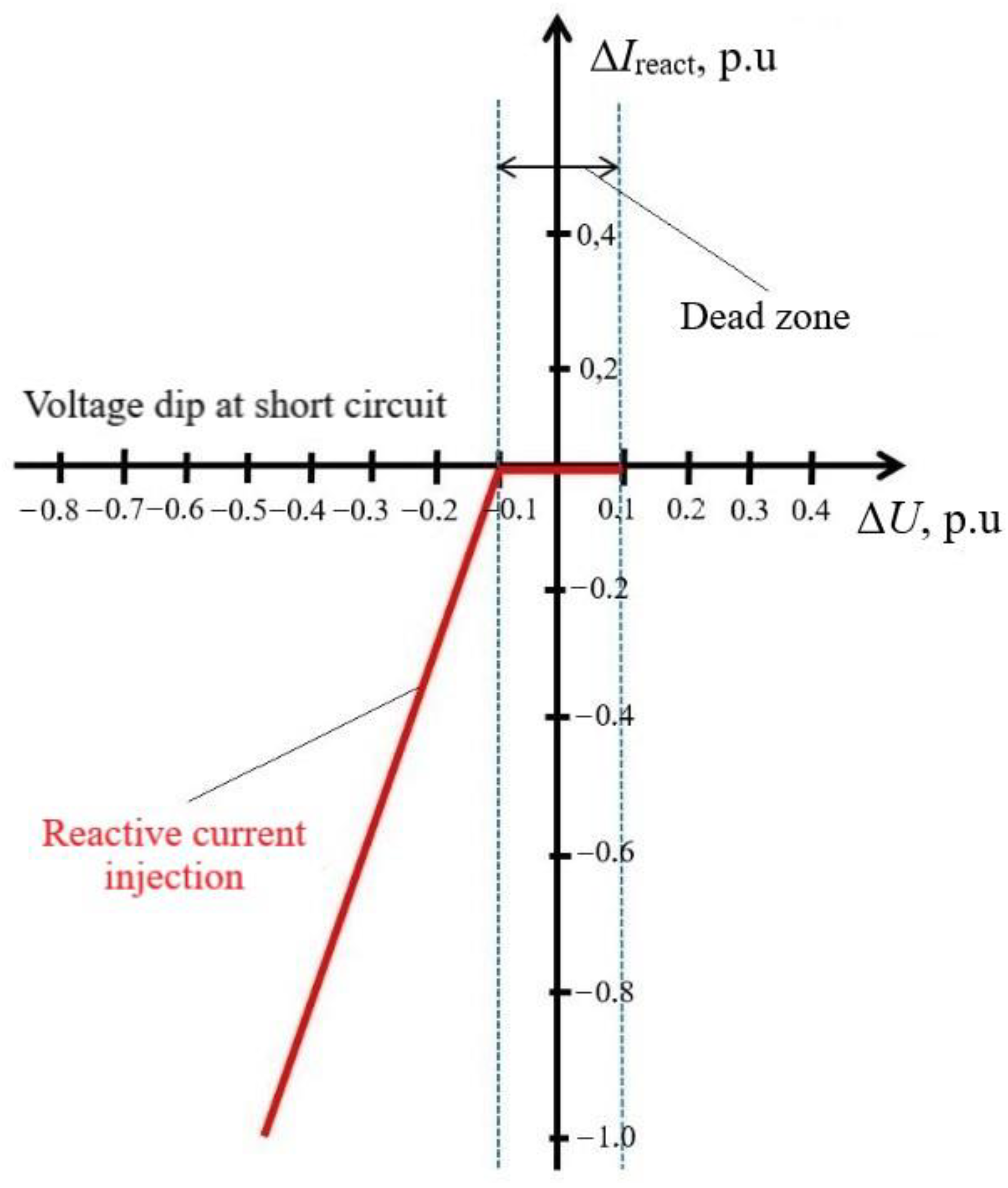
The graph of the relationship between the value of the injection of the wind turbine reactive current and the depth of the voltage dip during a short circuit in the distribution network is shown in Figure 2.
The dead zone (dotted lines in Figure 2) can be set from 0 p.u. to the required value. In Figure 2, reactive current injection starts at a voltage dip (ΔU) of 0.1 p.u. The reactive current injection increment coefficient (K) can vary from 0 to 10, according to the E.ON requirements K = ΔIreactU = 2. In the automatic control system (ACS) of inverters, one can set the priority of active or reactive power supply (combination in proportion). Moreover, the value of the injected reactive current can be added to that in the pre-accident conditions, but not more than 1.024 Irated [29].
According to the E.ON requirements, the time for fixing a voltage dip should be less than 10 ms, and the time for stopping the supply of active power should not exceed 10 ms from the time the short circuit began. The maximum time before the start of reactive current injection should be no more than 10.1 ms, and the maximum time until the reactive current reaches 0.9 (0.95) Irated should be no more than 50 (55) ms. The time for the reactive current to reach the set steady-state value in the range of +20%/-10% should be no more than 80 ms. The maximum short-term excess of the reactive current over the steady-state value should not exceed 0.1 Irated. All time intervals are counted from the beginning of the voltage dip at the output of the wind turbine inverter during a short circuit.
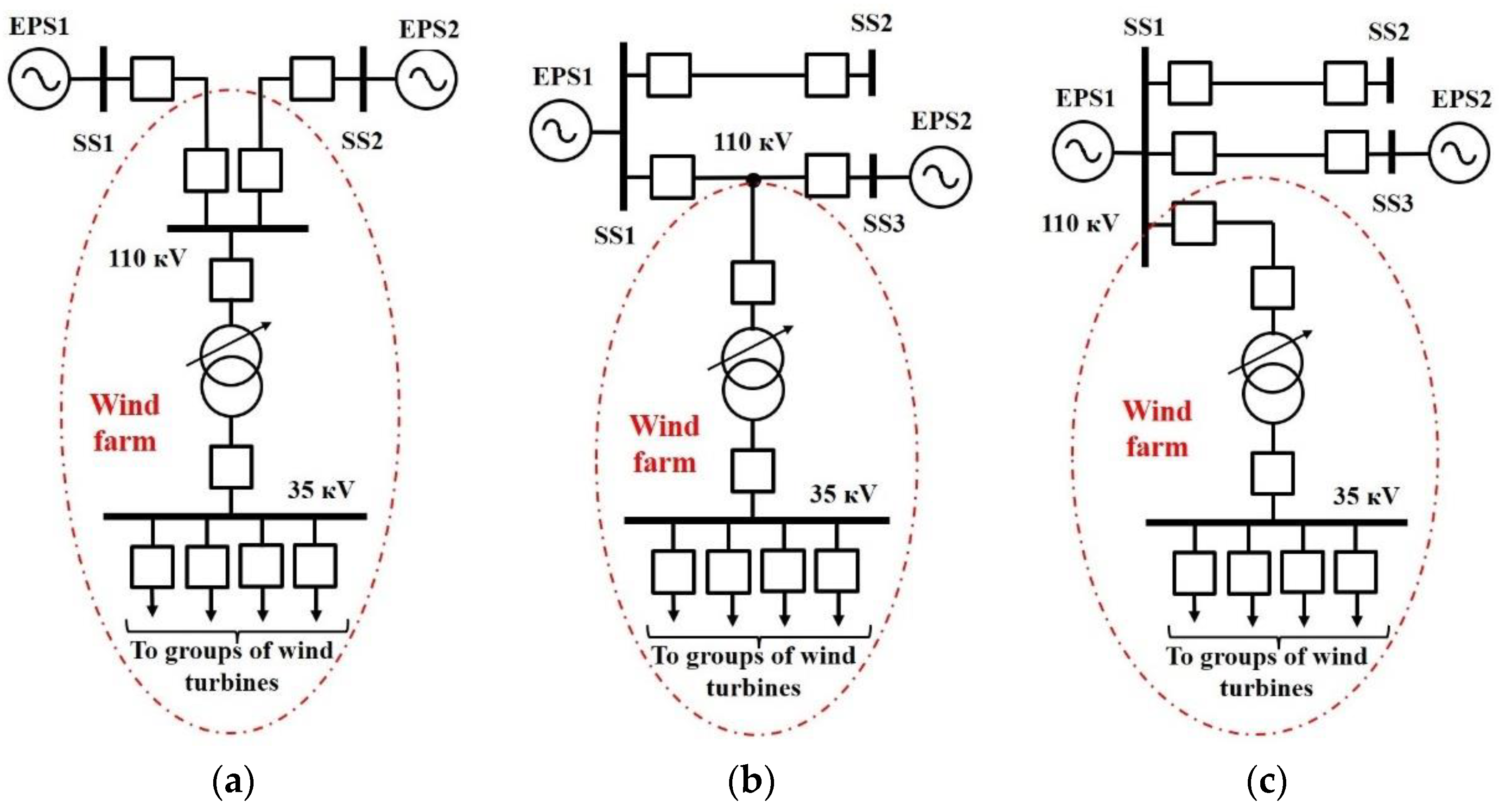
The Ures value at the output of wind turbine inverters in the case of standard disturbances in the distribution network also depends on the wind farm connection scheme. As a rule, one of the three schemes shown in Figure 3 is used to connect a wind farm to the 69 kV network.
There is a high probability of wind turbine outages in case of standard disturbances near the busbars of substation (SS), to which the wind farm is connected according to the scheme in Figure 3a,c. The probability of wind turbine shutdowns is lower when a wind farm is connected according to the scheme in Figure 3b. This is because a disturbance on power transmission line with a branch line to the wind farm is not subject to consideration according to the requirements of some grid codes.

3. Materials and Methods

Transients in the distribution network to which the wind farm is connected were calculated using the PowerFactory software.
The computational model of the power system contains 920 nodes, 53 generators, 225 transmission lines with a voltage of 35 kV and above, as well as 227 power transformers and autotransformers.
The computational model of a wind farm includes collection network; verified models of wind turbines with an inverter and ACS; common wind farm controller; wind turbine controllers; protection of wind turbine inverters, including the LVRT capability.
In the computational model, the collection network of the wind farm is represented by the technical characteristics (R, X, B) of the cable transmission lines that are used to connect the wind turbines to each other and that are connected to the 35 kV switchgear of step-up power transformers and the wind farm auxiliary load [30].
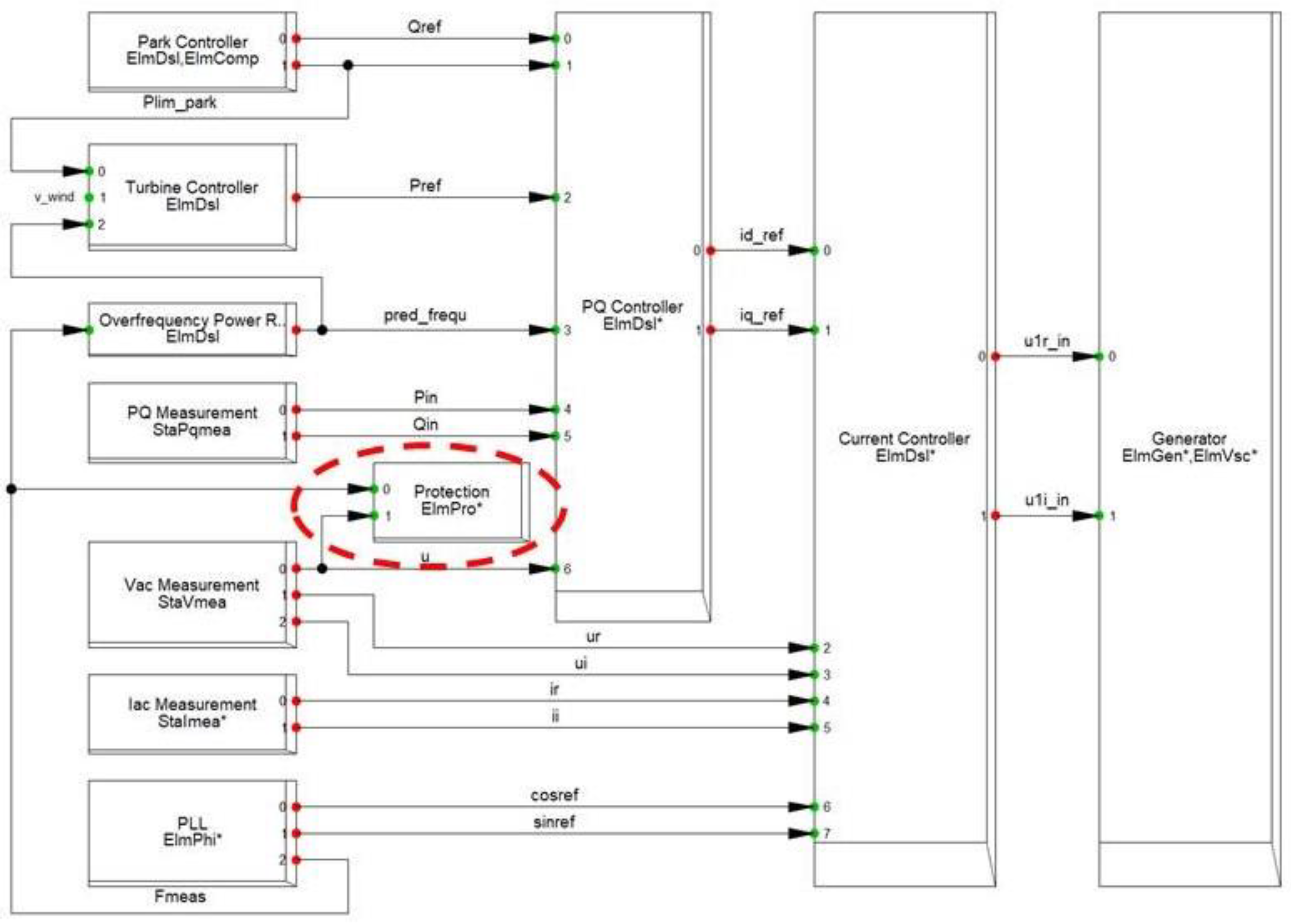
The verified wind farm model contains a large number of technical characteristics. The “Protection” module is used as part of the dynamic model of the wind turbine generator (Figure 4) to set the parameters for the LVRT characteristic settings.
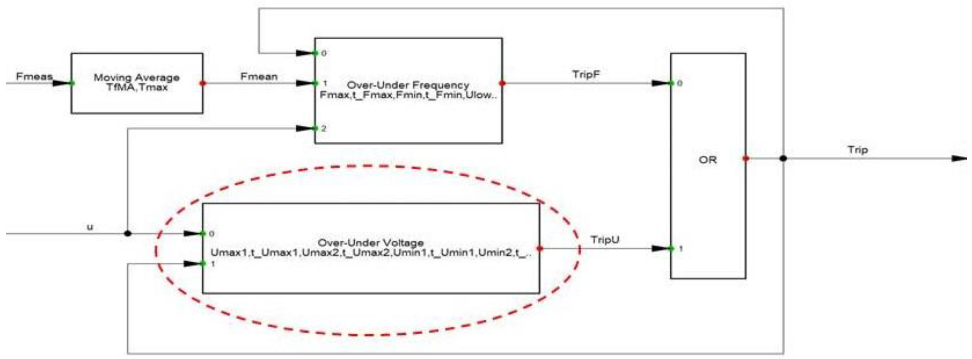
The structure of the "Protection" module is shown in Figure 5, which includes an "Over-Under Voltage" block. It contains logical elements that compare the measured voltage value (magnitude) and the duration of the voltage dip at the output of the wind turbine inverter with the specified settings for the LVRT characteristic. With a greater depth and duration of the voltage dip, the "Over-Under Voltage" block generates a command to turn off the 690 V wind turbine circuit breaker.
The list of standard disturbances in 110-220 kV distribution networks is given in Table 1 [31].
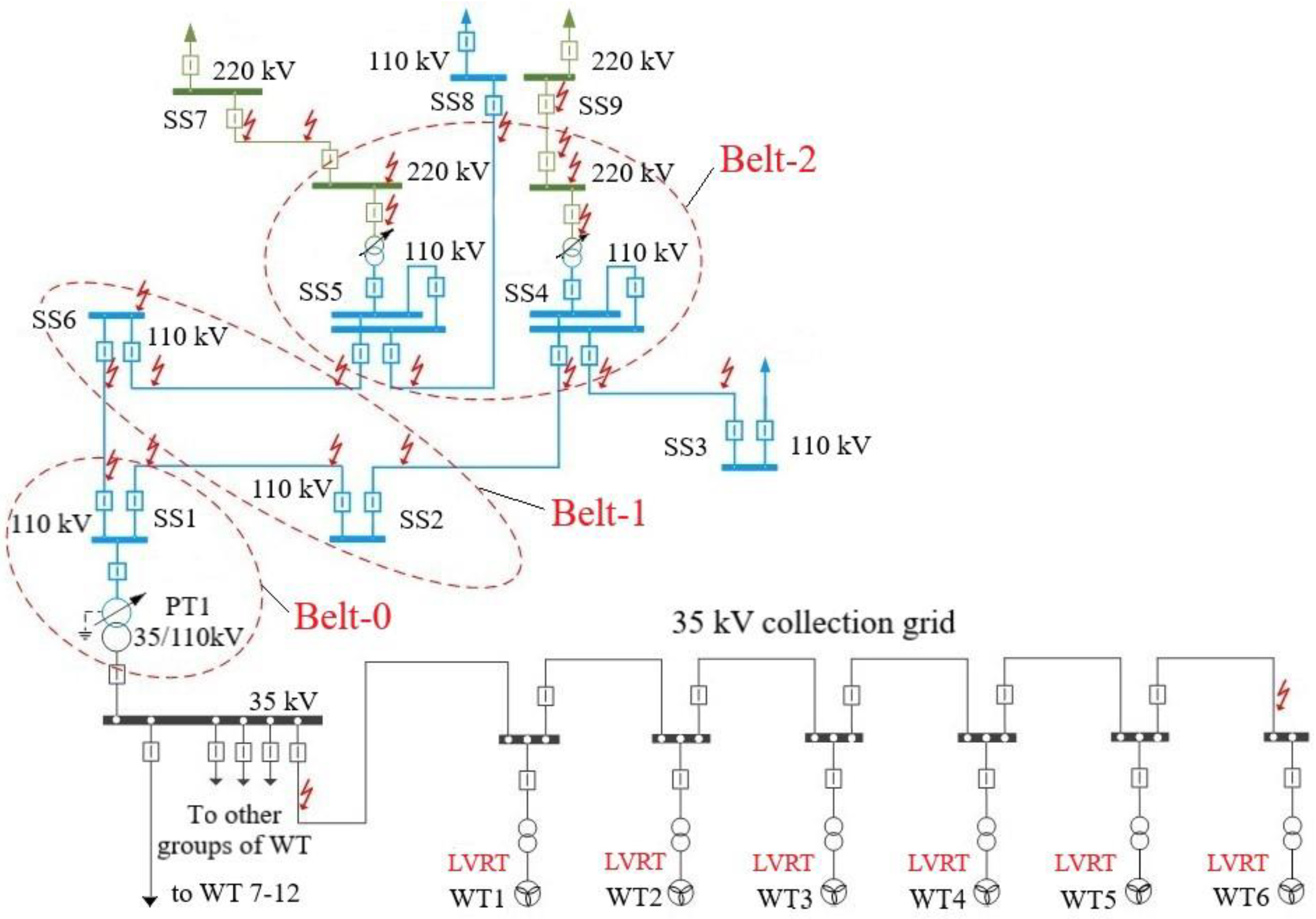
Figure 6 shows the schemes for the connection of wind farms with a total capacity of 41.64 MW (12 wind turbines with a capacity of 3.47 MW each) to a 110 kV distribution network.
The correctness of the choice of parameters for the setting of LVRT characteristic of wind turbines was assessed by comparing the results of calculation of Ures at the output of the wind turbine inverters with the settings of the LVRT characteristic.
The calculations factored in the total short-circuit clearance time, including the opening time of high-voltage circuit breakers, and the operating time of relay protection devices (main protection; second and third stages of backup protection) and automatic controls (automatic reclosing and breaker failure protection) [32,33].
In the cases where the wind turbine LVRT capability operation was triggered under standard disturbances, the study area was expanded until the wind turbine LVRT was enabled. This is necessary to assess the possibilities for changing the settings of relay protection devices in the distribution network or modifying them.

4. Results

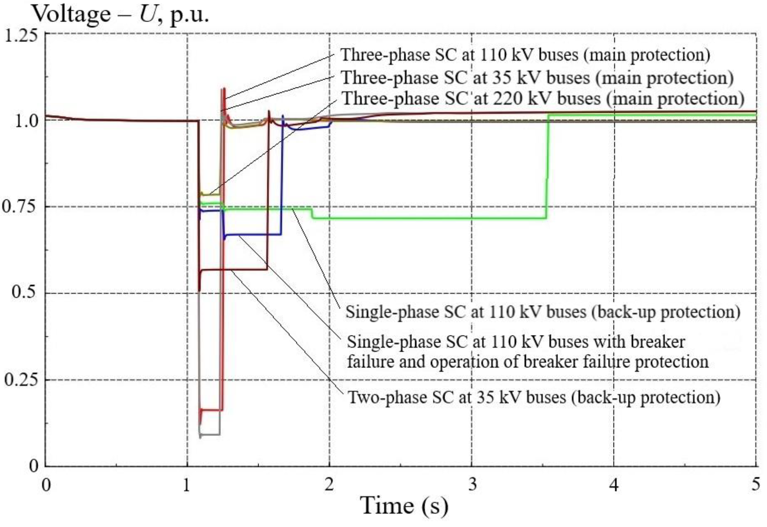
Standard disturbances in the distribution network were analyzed for belts 0, 1, and 2 (Figure 6). The standard disturbances leading to the disconnection of power grid components during the clearance of short circuits, causing disconnection of the wind farms from the distribution network, were not considered. Figure 7 shows the results of calculations of Ures at the output of the wind farm inverter, which were performed in accordance with Table 1.
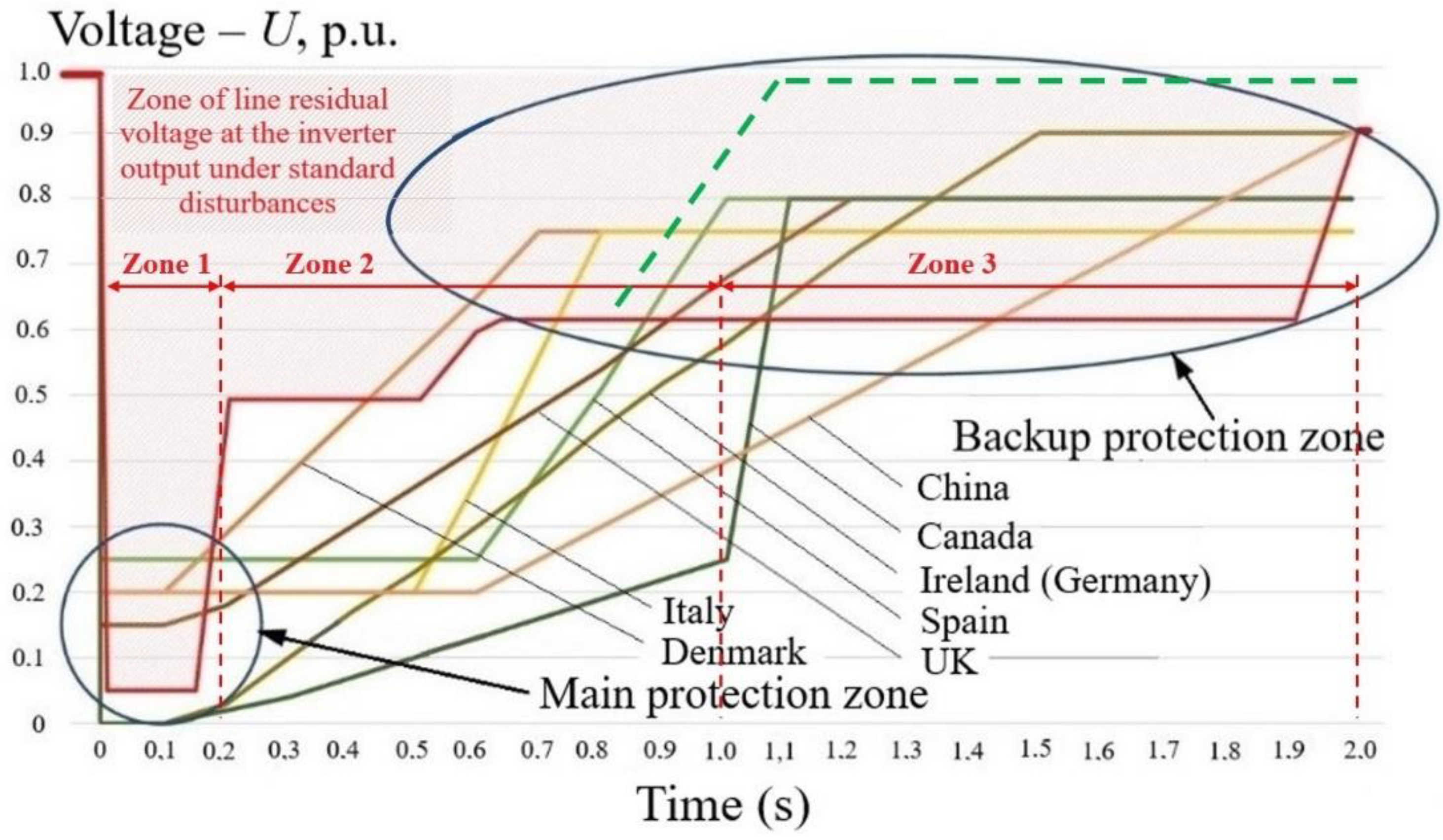
Figure 8 shows the voltage-time characteristics for LVRT of wind turbine inverters from the grid codes of different countries in comparison with the graph of changes in Ures at the output of wind turbine inverters (red solid line) when simulating standard disturbances in the distribution network.
Let us analyze the three zones shown in Figure 8, which are characterized by different times of short circuit clearance by relay protection devices:
  • Zone 1 (0 – 0.2 s) is characterized by the fact that the parameters for setting the LVRT characteristics according to the requirements of the grid codes of Denmark, Italy, Spain, UK, and China do not provide prevention of wind turbine shutdowns. This is because the value of Ures at the output of wind turbine inverters is lower than the settings of the LVRT characteristic. Grid codes in some countries allow wind turbine shutdown when Ures drops below 15 – 25 % Urated with a duration of 0.1-0.15 s. At the same time, the requirements of the grid codes of Germany, Ireland, and Canada make it possible to ensure the stable operation of wind turbines under standard disturbances in the analyzed time interval.
  • Zone 2 (0.2 – 1.0 s) is characterized by the fact that most wind turbine manufacturers ensure that the required Ures value is maintained at the output of wind turbine inverters under standard disturbances. Therefore, with single-phase short circuits (more than 70% of the total number) eliminated by backup protections (the second stage region) with a time delay of up to 1 s, there will be no wind turbine shutdowns. However, the requirements of the grid codes of Denmark, Italy, Spain, and UK do not allow preventing disconnections of wind turbines.
  • Zone 3 (more than 1 s) is distinguished in that when a single-phase short circuit lasting more than 1-2 s is cleared by backup protections (the second or third stage region), in the vast majority of cases, wind turbines will be shut down. In some countries however, in distribution networks with voltage above 69 kV, wind turbines must continue to operate stably up to 2.5 s.
Long response times of the second and third stages of back-up protection (remote; ground fault protection) are due to the need to ensure selective operation of relay protection devices based on electromechanical relays that are in operation in large numbers [34,35].
An analysis of calculations of transients in distribution networks with standard disturbances indicates that the settings for the LVRT characteristic, given by some manufacturers of wind turbines, require adjustment. This is justified if Ures at the output of the wind turbine inverter is below 20 % Urated, and also in the event of a short circuit in the network being eliminated by the backup protections with time delays of more than 1 s, which implement the long-range backup function [36,37]. Otherwise, the wind turbines will be disconnected.
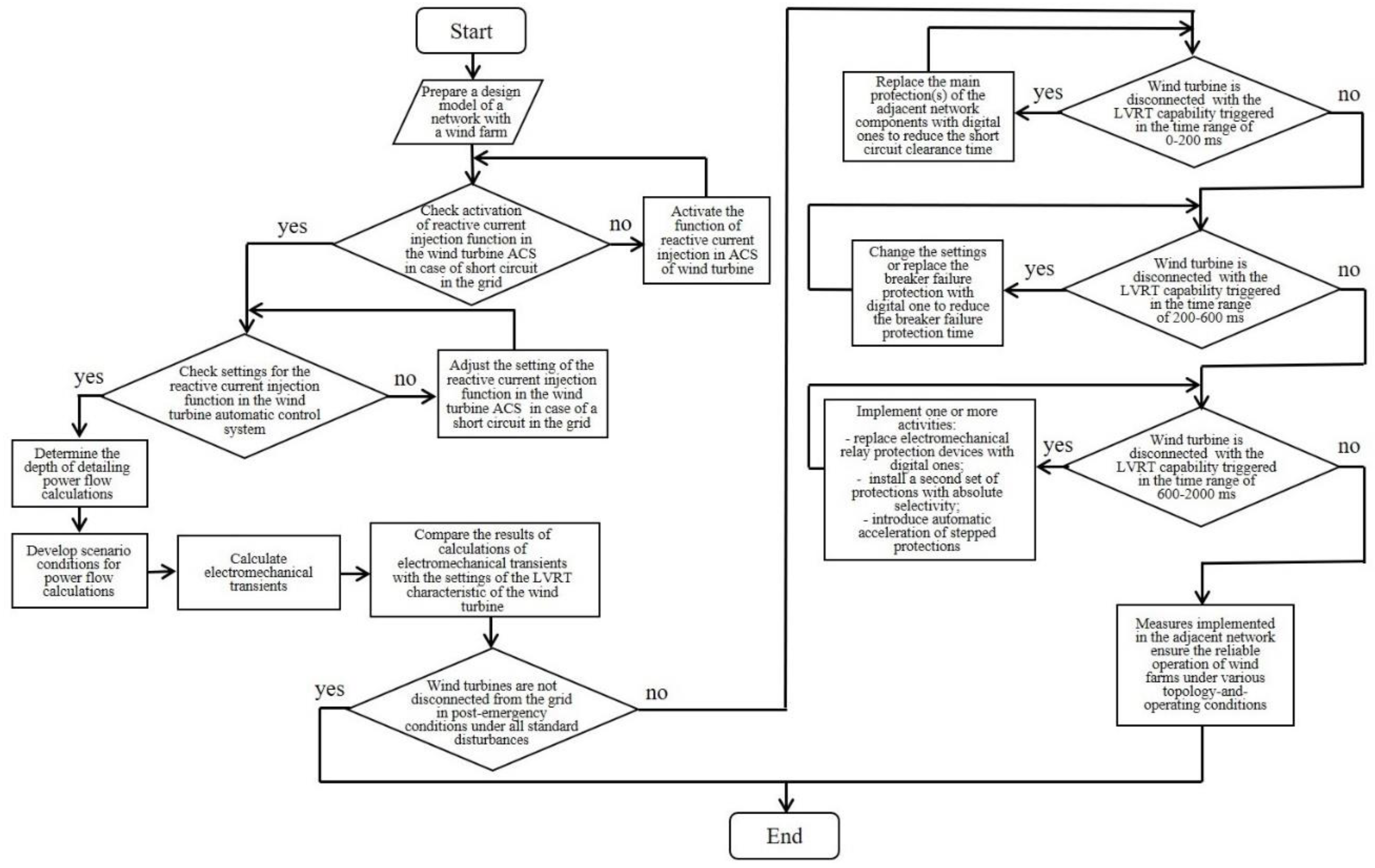
A methodology was developed to check the settings of the LVRT characteristic for compliance with the technical requirements for wind turbines. Figure 9 shows a block diagram of the verification algorithm.
The block diagram of the algorithm (Figure 9) shows the sequence of actions to design a wind power evacuation arrangement or check the results of power flow calculations performed by the design organization.
Next, we will consider methods for ensuring the stable operation of wind turbine inverters under standard disturbances in the distribution network.
1. 
Upgrading relay protection devices and automatic controls in the distribution network adjacent to the wind farm.
Zone 1 (Figure 8) requires reducing the response time of the main protection of power lines by replacing the electromechanical relay protection devices with digital ones, which have a higher sensitivity and a shorter response time. It may also be necessary to replace high-voltage circuit breakers with modern (SF6 or vacuum) ones, with a shorter opening time. However, the reduction in the short circuit clearance time does not allow preventing wind turbine shutdowns at close short circuits with a deep voltage dip.
Zone 2 (Figure 8) requires modernizing the backup protections to reduce the response time of the second and third stages to 0.9 – 1.0 s. It may also be necessary to reduce the response time of the breaker failure protection by changing the settings or by replacing it with a digital one.
Zone 3 (Figure 8) requires placing the second sets of relay protection devices with absolute selectivity as backup protection on power lines and implementing automatic introduction of backup protection acceleration (remote, ground fault protection). This will increase the value of Ures at the output of wind turbine inverters, as shown by the green dotted line in Figure 8.
2. 
Activating the reactive current injection function at the wind turbine during short circuit.
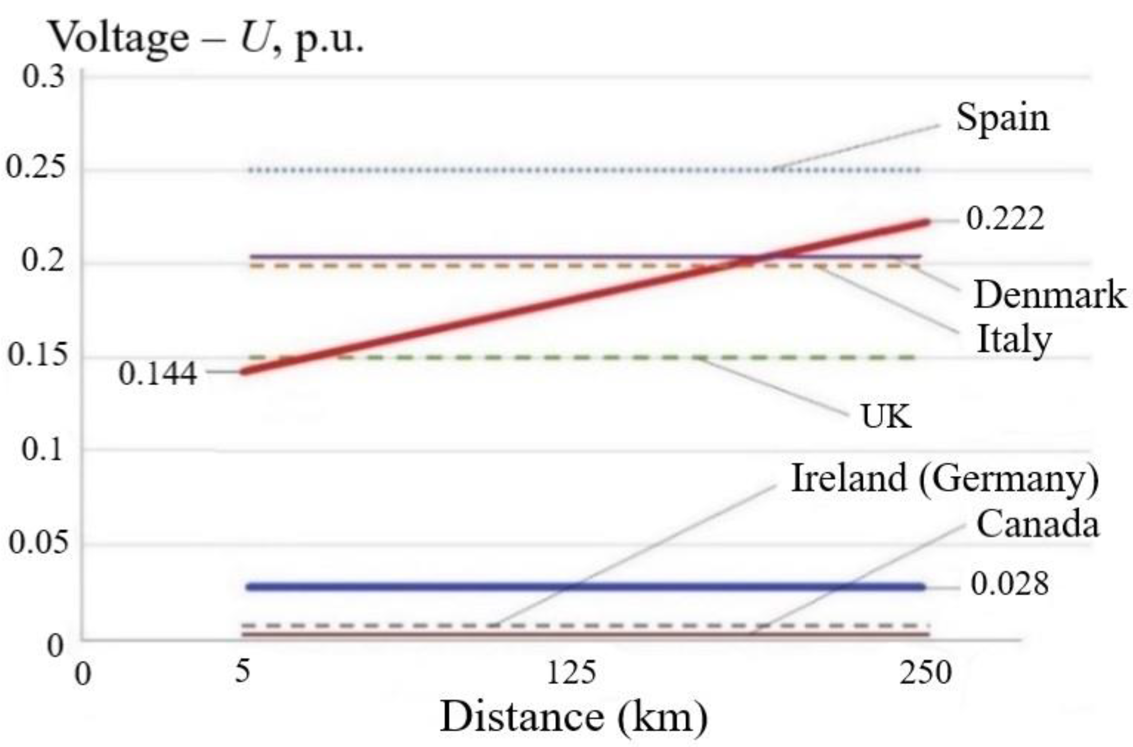
Analysis of the efficiency of activating the reactive current injection function at the wind turbine during a short circuit in the distribution network involved constructing a graph of the relationship between the value of Ures at the outputs of wind turbine inverters during three-phase short circuits at outgoing power lines and a distance between the wind farm and 220/110 kV substation based on the results of calculations of transient processes (Figure 10). The time of short circuit clearance by relay protection devices is taken up to 200 ms at various distances between the wind farm and the 220 kV substation (Figure 6).
Figure 10 shows the requirements of the grid codes of various countries for the value of Ures, at which the wind turbine should not be disconnected. The calculated values of Ures at the outputs of the wind turbine inverters when the reactive current injection function is activated at the wind turbine during a short circuit in the distribution network are shown by a red solid line, and when deactivated – by a blue one (Figure 10).
Analysis of Figure 10 suggests that the activation of the reactive current injection function at the wind turbine produces a significant positive effect in the form of an increase in the Ures value at the output of wind turbine inverters from 0.028 Urated to 0.222 Urated, i.e., 5-8 times, depending on the distance between the wind farm and the 220 kV substation.
The Ures value goes up as the distance from the wind farm to the 220 kV substation increases, which is due to the generation of significant reactive power by extended 110 kV transmission lines with their low active power load. Comparison of Ures at the output of wind turbine inverters with LVRT characteristics shows that the activation of the reactive current injection function helps to prevent unnecessary shutdowns of wind turbines produced by most manufacturers.
In the event that the wind turbine does not have the function of reactive current injection in case of short circuit in the distribution network, a requirement for the wind turbine should be established similar to the requirement of the grid codes of Germany, Ireland and Canada (Ures = 0 p.u.). This will prevent excessive shutdowns of wind turbines in zone 1 (Figure 8).
3. 
Installing additional electrical devices at wind farms.
Consider the installation of the following electrical devices in a 35 kV wind farm switchgear:
  • STATCOM;
  • current-limiting reactor (CLR).
Main technical characteristics of STATCOM are:
  • nominal voltage: 35 kV;
  • nominal power: 30 MVA;
  • operating voltage range: 80 % UratedUoper ≤ 120 % Urated;
  • speed: 5-10 ms;
  • protection setting to turn off when the voltage drops below 80 % Urated: toff = 50 ms.
The option of connecting STATCOM to the busbars of 35 kV wind farm was considered.
As shown by calculations of transient processes during short circuit in zones 1, 2 (Figure 8), accompanied by a voltage dip below 80 % Urated, STATCOM is switched off by its protection. With remote short circuits, when Ures at the STATCOM terminals is higher than 80 % Urated, the voltage at the output of wind turbine inverters increases from 80.6 % Urated to 85.7 % Urated (i.e., by 6.3%) [38]. In zone 3 (Figure 8), however, wind turbines are unnecessarily turned off only when the backup protection response time in the distribution network is more than 1 s. Thus, the performance of STATCOM is extremely low, given its significant cost.
Main technical characteristics of CLR are:
  • nominal voltage: 35 kV;
  • nominal current: 1000 A;
  • inductive reactance (XCLR): from 1 to 10 Ohm.
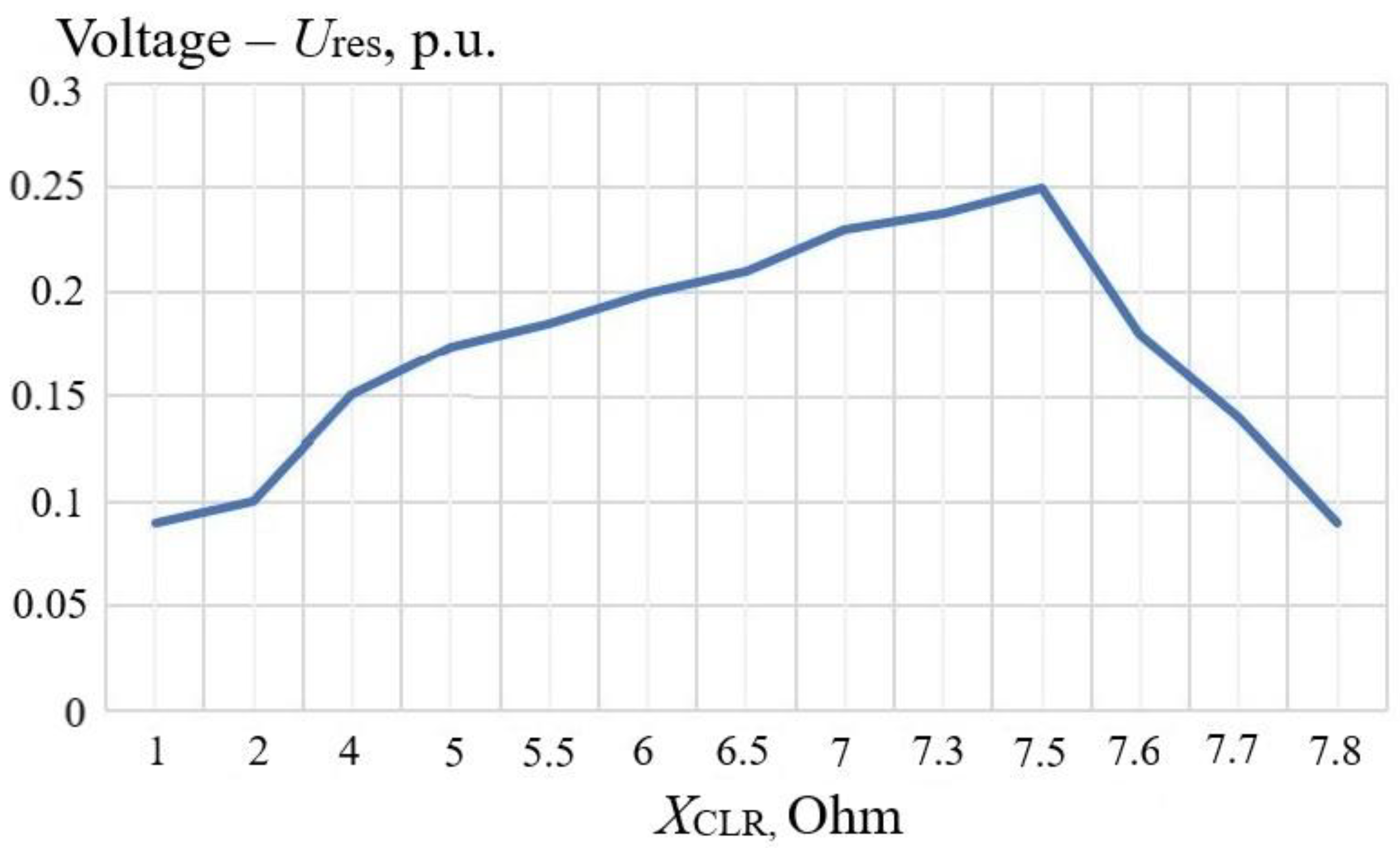
The research also addressed an option of series connection of the CLR in the circuit of a 35/110 kV step-up transformer of the wind farm on the 35 kV side. Multivariate calculations of transients were performed during a three-phase short circuit at a 110 kV power transmission line with its shutdown (near the buses of the 220/110 kV substation) at various XCLR values. The results of calculations of the Ures value at the output of the wind turbine inverters show that the greatest effect is achieved at XCLR = 7.5 Ohm (Figure 11).
The use of CLR made it possible to increase Ures at the output of wind turbine inverters with a short circuit clearance time of up to 0.9 – 1 s:
  • from 8 % Urated to 25% Urated (increase by 213 %) for three-phase short circuits;
  • from 40 % Urated to 60% Urated (increase by 50 %) with two-phase short circuits;
  • from 68 % Urated to 76% Urated (increase by 12 %) with single-phase short circuits.
The obtained LVRT characteristic when connecting the CLR (red dotted line in Figure 8) makes it possible to ensure the stable operation of wind turbines manufactured in accordance with the requirements of the grid codes of UK, China, Spain, Denmark, Ireland, Germany, Canada, and Italy.
For each case of the wind farm connection to the distribution network, XCLR should be determined based on the results of transient calculations. The CLR performance is quite high, although its cost is about six times less than that of STATCOM. For the economic analysis to be correct, one should take into account the cost of electricity losses in the CLR and operating costs throughout its life cycle.
4. 
Making changes to the hardware of wind turbine inverters.
An individual technical solution is to make changes to the hardware of wind turbine inverters to adjust the LVRT characteristic. Stable operation of the inverter can be provided by maintaining the balance of power transmission from the wind generator through the rectifier to the DC link and to the input of the inverter. In each link of the inverter controller, the wind turbine ensures that the operating parameters are maintained within the range of feasible values. A specific feature of the inverter is that with the help of the Phase-Locked Loop (PLL) system, the shape, frequency and phase of the alternating current are formed at its output in accordance with the shape, frequency, and phase of the voltage in the wind farm collection network.
Stable operation of all units of the wind turbine inverter controller is possible at a voltage of at least 20 % Urated in the wind farm collection network. If the voltage at the PLL unit is below 20 % Urated, the reactive current injection function is temporarily blocked, and if the duration of the voltage dip exceeds the set value of the LVRT characteristic, the wind turbine is switched off.
These restrictions on the operation of the wind turbine inverter are due to:
  • the value of the capacitance of the capacitor used in the DC link between the rectifier and the inverter;
  • the power supply to the control circuits of the inverter controller from the DC link;
  • generation of erroneous signals in the PLL unit when the voltage at its input is below 20 % Urated.
Let us determine the parameters of the capacitance of the capacitor in the DC link of the wind turbine, which are necessary for the implementation of two main functions:
  • smoothing the ripples related to the operation of the rectifier;
  • eliminating the overvoltage caused by switching of the inverter power switches and by the variable schedule of the wind generator operation.
To ensure the stable operation of the wind turbine in case of voltage dips in the distribution network, we determine the minimum requirements for the parameters of the capacitor in the DC link. Let us do this following the condition of maintaining the value of reactive current injection by the wind turbine inverter during a standard disturbance with a voltage dip of up to 20 % Urated within 0.2 s.
The capacitance of the capacitor in the DC link can be determined knowing the amount of energy accumulated in the capacitor before the onset of a standard disturbance, considering the law of conservation of energy. The energy stored in the capacitor is calculated by formula (1):
W = C c a p · U d 2 2 = U r e s · I r · t ,
where Ccap – capacitance of the DC link capacitor; Ud – voltage of the DC link (Ulin/0.87 – with a six-pulse inverting circuit; Ulin = 690 V); Ures – residual voltage at the inverter output taken equal to 20 % Urated = 0.2 · 690 = 138 V; Ir – reactive current injection taken equal to I r a t e d = I r = S r a t e d 3   U l i n = 2778   3   ·   690 = 2,324   A ; ∆t – the duration of the voltage dip assumed to be 0.2 s.
Calculate the required capacitance of the capacitor by expression (2):
C c a p = 2 · U r e s   ·   I r   ·   t U d 2 = 2 · 138   ·   2,324   ·   0.2 ( 690 / 0.87 ) 2 = 0.204 F
In the inverter, the capacitance of the capacitor is selected according to the criterion of smoothing ripples and is 0.03 F, i.e., seven times less than the calculated value. This does not allow injection of reactive current in the event of a voltage dip with a duration of 0.2 s, which leads to the shutdown of the wind turbine by the protection unit due to a decline in the voltage in the DC link below the permissible value [39,40].
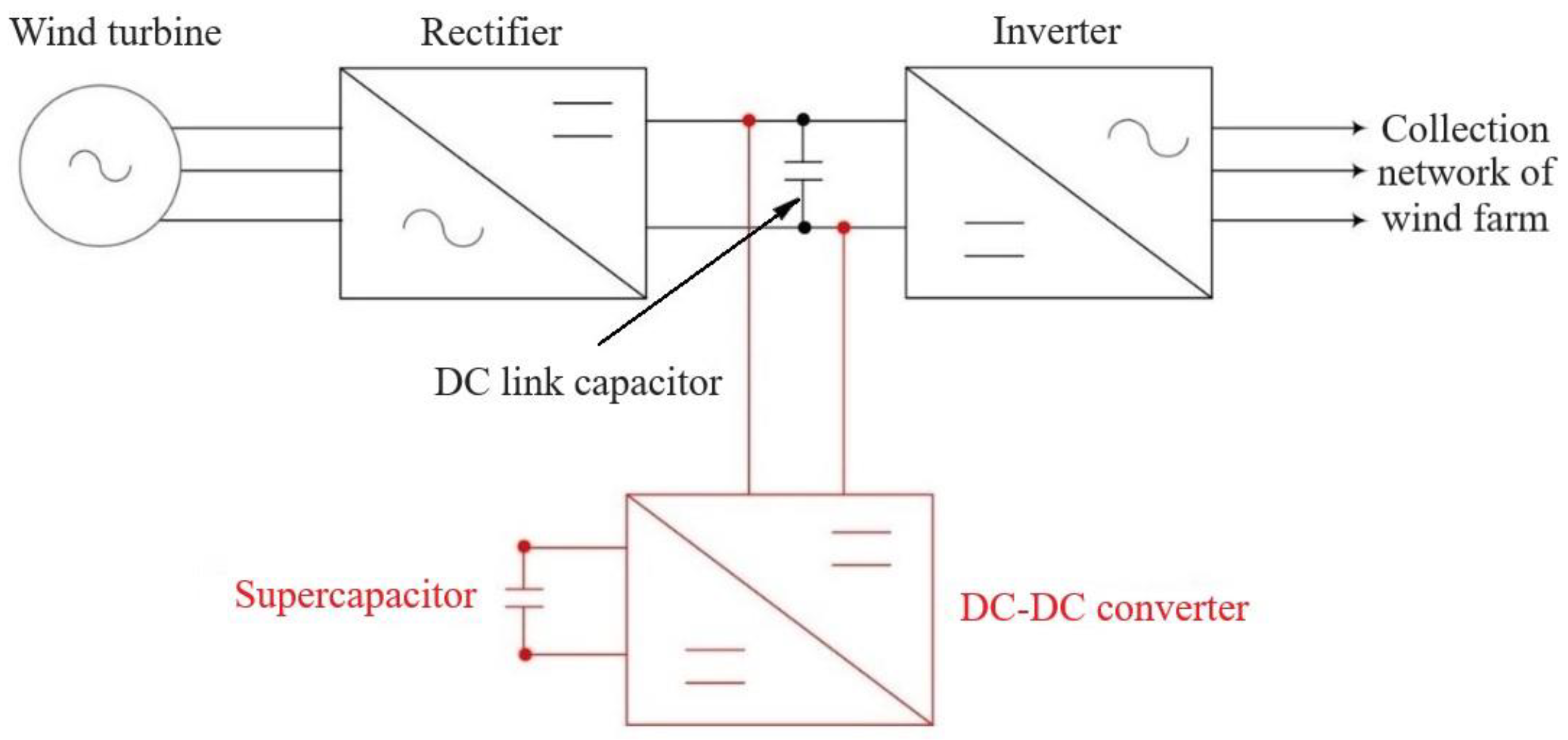
To maintain the voltage in the DC link during a voltage dip, it is necessary to additionally install a capacitance of 0.17 F in the form of a supercapacitor. Given the specific feature of the supercapacitor (low voltage on the plates is 2.7 V), it is required to additionally install a DC-DC converter to increase the voltage to 800 V in order to connect the wind turbine inverter to the DC link, as shown in Figure 12.
Let us calculate the capacitance of the supercapacitor in terms of the law of conservation of energy and the required value of additional capacitance – 0.17 F:
W = C a d d . c a p   · U d 2 2 = C s u p e r c a p   · U d s u p e r c a p 2 2 C s u p e r c a p = C a d d . c a p · U d 2 U d s u p e r c a p 2 = 0.17 · 800 2 2.7 2 = 14,924 F
Given the obtained calculated capacitance value, we use five Maxwell 2.7V 3000F supercapacitors and one 10 kW DC-DC converter 2.7V/800V. The cost of equipment for the implementation of the proposed technical solution at each wind turbine is significantly lower than the cost of CLR, and even more so than the cost of STATCOM. However, in order to maintain warranty obligations for the wind turbine, its implementation should be agreed with the wind turbine manufacturer.

5. Discussion

With an increase in the number of wind farms and their total capacity in the structure of generating capacities, special attention should be paid to the issues of their stable operation in order to prevent the blackouts and their development with mass disconnection of consumers [41,42].
International experience suggests that over the past decade, different countries have gradually tightened the requirements for connection and operation of the wind farms within electric power systems.
Mass shutdowns of wind turbines during standard disturbances in the distribution network can lead to emergency increase in the load for the generating units of conventional power plants, power transmission lines and power transformers, thereby causing a heavy-load conditions.
A list of standard disturbances to be analyzed to design the wind power evacuation arrangement in individual countries may differ significantly from the requirements of the grid codes of the countries where the wind turbines are designed and/or manufactured.
Manufacturers of type IV wind turbines must adapt the LVRT characteristics to the requirements of the grid code of the country where the wind turbine is delivered or the technical solutions will have to be implemented by the owner of the wind farm.
To confirm the compliance of wind turbines with the requirements of the grid code of a particular country, it is necessary to calculate transient processes and simulate standard disturbances. The purpose of this is to compare the results of calculations of the residual voltage at the outputs of wind turbine inverters with the settings for the LVRT characteristic. The analysis should be carried out in the three operating zones discussed in the paper.
The countries where the grid codes have no requirements to set the LVRT characteristic and ensure the injection of reactive current and the rate of its rise in the event of a voltage dip at the output of wind turbine inverters, should introduce them. After their introduction, it is necessary to implement a procedure for confirming the compliance of all wind turbines in operation with the new requirements.
According to the experience gained in the world, the frequent reasons for excessive shutdowns of wind turbines are the incorrect choice of settings for the LVRT characteristic of wind turbines, the function of reactive current injection in case of short circuit in the distribution network, and for the protection devices and automatic controls in the distribution network.
The calculations of transient processes allow the following conclusions to be made about the performance of various methods for preventing outages of wind turbines:
  • modernization of relay protection devices with replacement of electromechanical devices with digital ones can reduce the response time of the second and third stages of backup protections to 0.9 – 1.0 s. In addition, the second sets of relay protection devices with absolute selectivity should be used as backup protections with automatic introduction of accelerated stepped protections;
  • activation of the wind farm reactive current injection function, which can be incorrectly set, and in some cases disabled, makes it possible to increase the residual voltage at the output of the wind turbine inverters with a short-circuit duration of up to 0.2s and prevent unnecessary shutdowns of the wind turbine;
  • application of STATCOM is ineffective for stable operation of wind turbines under standard disturbances in the distribution network due to the narrow range of operating voltage 80 % UratedUoper ≤ 120% Urated;
  • series connection of CLR in the circuit of 35/110 kV step-up transformer of a wind farm is effective as it increases the residual voltage at the outputs of inverters of the wind turbines and prevents their excessive shutdowns. In each case of wind farm connection to the distribution network, XCLR should be determined based on the results of transient calculations;
  • the most effective technical solution is to make changes to the hardware of wind turbine inverters, with the installation of a block of supercapacitors and a DC-DC converter. This enables the adjustment of the operating range of the LVRT characteristic and prevent unnecessary shutdowns of the wind turbine under any type of standard disturbances. At the same time, there is no need to upgrade relay protection devices and automatic controls in the distribution network.

6. Conclusions

In the event that the wind turbine does not comply with the requirements of the grid code of a particular country for stable operation under standard disturbances, it is necessary to implement technical measures at the wind farm and/or in the distribution network to reduce the depth of voltage dips and the duration of short circuit clearance.
A methodology and an algorithm were developed to verify the parameters of the LVRT characteristic of a wind turbine to be set when connecting a wind farm to a distribution network to ensure their stable operation under various topology and operating conditions.
Three operating zones were identified and described, for which recommendations were developed and presented to modify and alter the settings of relay protection devices and automatic controls in the distribution network in order to reduce the short circuit clearance time.
The efficiency of activation of the reactive current injection function at all wind turbines in the case of a short circuit in the distribution network is proved, which makes it possible to increase the residual voltage at the inverter output and prevent unnecessary shutdowns of wind turbines in the time range up to 0.2 s.
Group and individual technical solutions are presented to ensure the stable operation of wind turbines under all types of standard disturbances, and their performance is assessed. The most effective technical solution involves making changes to the hardware of wind turbine inverters.

Author Contributions

Conceptualization, A.S. and P.I.; methodology, P.I and S.F.; software, A.S.; validation, K.S.; formal analysis, P.I.; investigation, A.S., K.S. and S.F.; resources, P.I.; data curation, K.S. and S.F.; writing—original draft preparation, A.S. and P.I.; writing—review and editing, S.F. and K.S.; visualization, A.S.; supervision, K.S.; project administration, P.I.; funding acquisition, S.F. All authors have read and agreed to the published version of the manuscript.

Funding

This research received no external funding.

Data Availability Statement

Data sharing not applicable. No new data were created or analyzed in this study. Data sharing is not applicable to this article.

Conflicts of Interest

The funders had no role in the design of the study; in the collection, analyses, or interpretation of data; in the writing of the manuscript, or in the decision to publish the results.

References

  1. Beyza, J.; Yusta, J.M. The effects of the high penetration of renewable energies on the reliability and vulnerability of interconnected electric power systems. Reliability Engineering & System Safety 2021, 215, 107881. [Google Scholar] [CrossRef]
  2. Panda, A.; Dauda, A.K.; Chua, H.; Tan, R.R.; Aviso, K.B. Recent advances in the integration of renewable energy sources and storage facilities with hybrid power systems. Cleaner Engineering and Technology 2023, 12, 100598. [Google Scholar] [CrossRef]
  3. Gorman, W.; Mills, A.; Wiser, R. Improving estimates of transmission capital costs for utility-scale wind and solar projects to inform renewable energy policy. Energy Policy 2019, 135, 110994. [Google Scholar] [CrossRef]
  4. Xiao, M.; Junne, T.; Haas, J.; Klein, M. Plummeting costs of renewables - Are energy scenarios lagging? Energy Strategy Reviews 2021, 35, 100636. [Google Scholar] [CrossRef]
  5. Dvorak, A.J.; Victoria, M. Key Determinants of Solar Share in Solar- and Wind-Driven Grids. IEEE Journal of Photovoltaics 2023, 13, 476–483. [Google Scholar] [CrossRef]
  6. Russo, M.A.; Carvalho, D.; Martins, N.; Monteiro, A. Forecasting the inevitable: A review on the impacts of climate change on renewable energy resources. Sustainable Energy Technologies and Assessments 2022, 52, 102283. [Google Scholar] [CrossRef]
  7. Zhong, J.; Bollen, M.; Rönnberg, S. Towards a 100% renewable energy electricity generation system in Sweden. Renewable Energy 2021, 171, 812–824. [Google Scholar] [CrossRef]
  8. Saffari, M.; Mc. Pherson, M. Assessment of Canada's electricity system potential for variable renewable energy integration. Energy 2022, 250, 123757. [Google Scholar] [CrossRef]
  9. Avazov, A.; Colas, F.; Beerten, J.; Guillaud, X. Application of input shaping method to vibrations damping in a Type-IV wind turbine interfaced with a grid-forming converter. Electric Power Systems Research 2022, 210, 108083. [Google Scholar] [CrossRef]
  10. Rahimi, M.; Assari, H. Addressing and assessing the issues related to connection of the wind turbine generators to the distribution grid. International Journal of Electrical Power & Energy Systems 2017, 86, 138–153. [Google Scholar] [CrossRef]
  11. Jiang, Z.; Xing, Y. Load mitigation method for wind turbines during emergency shutdowns. Renewable Energy 2022, 185, 978–995. [Google Scholar] [CrossRef]
  12. Wang, A.; Pei, Y.; Zhu, Y.; Qian, Z. Wind turbine fault detection and identification through self-attention-based mechanism embedded with a multivariable query pattern. Renewable Energy 2023, 211, 918–937. [Google Scholar] [CrossRef]
  13. Ilyushin, P.; Filippov, S.; Kulikov, A.; Suslov, K.; Karamov, D. Specific Features of Operation of Distributed Generation Facilities Based on Gas Reciprocating Units in Internal Power Systems of Industrial Entities. Machines 2022, 10, 693. [Google Scholar] [CrossRef]
  14. Yadav, M.; Pal, N.; Saini, D.K. Low voltage ride through capability for resilient electrical distribution system integrated with renewable energy resources. Energy Reports 2023, 9, 833–858. [Google Scholar] [CrossRef]
  15. Chakraborty, A.; Maity, T. Integrated control algorithm for fast and accurate detection of the voltage sag with low voltage ride-through (LVRT) enhancement for doubly-fed induction generator (DFIG) based wind turbines. Control Engineering Practice 2023, 131, 105393. [Google Scholar] [CrossRef]
  16. Ilyushin, P.V.; Shepovalova, O.V.; Filippov, S.P.; Nekrasov, A.A. Calculating the Sequence of Stationary Modes in Power Distribution Networks of Russia for Wide-Scale Integration of Renewable Energy Based Installations. Energy Reports 2021, 7, 308–327. [Google Scholar] [CrossRef]
  17. Zeng, B.; Wang, J.; Shi, J.; Zhang, J.; Zhang, Y. A multi-level approach to active distribution system planning for efficient renewable energy harvesting in a deregulated environment. Energy 2016, 96, 614–624. [Google Scholar] [CrossRef]
  18. Ilyushin, P.; Kulikov, A.; Suslov, K.; Filippov, S. Consideration of Distinguishing Design Features of Gas-Turbine and Gas-Reciprocating Units in Design of Emergency Control Systems. Machines 2021, 9, 47. [Google Scholar] [CrossRef]
  19. Singh, B.; Sharma, J. A review on distributed generation planning. Renewable and Sustainable Energy Reviews 2017, 76, 529–544. [Google Scholar] [CrossRef]
  20. Filippov, S.P.; Dilman, M.D.; Ilyushin, P.V. Distributed Generation of Electricity and Sustainable Regional Growth. Thermal Engineering 2019, 12, 869–880. [Google Scholar] [CrossRef]
  21. Koivisto, M.; Maule, P.; Cutululis, N.; Sørensen, P. Effects of Wind Power Technology Development on Large-scale VRE Generation Variability. Proc. 2019 IEEE Milan PowerTech. [CrossRef]
  22. Mehigana, L.; Deanea, J.P.; Gallachóira, B.P.Ó.; Bertsch, V. A review of the role of distributed generation (DG) in future electricity systems. Energy 2018, 163, 822–836. [Google Scholar] [CrossRef]
  23. Li, R. Protection and control technologies of connecting to the grid for distributed power resources. Distributed Power Re-sources, 2019; 121–144. [Google Scholar] [CrossRef]
  24. Ilyushin, P.V. Analysis of the specifics of selecting relay protection and automatic (RPA) equipment in distributed networks with auxiliary low-power generating facilities. Power Technology and Engineering 2018, 6, 713–718. [Google Scholar] [CrossRef]
  25. Razavi, S.E.; Rahimi, E.; Javadi, M.S.; Nezhad, A.E.; Lotfid, M.; Shafie-khah, M.; Catalão, J.P.S. Impact of distributed generation on protection and voltage regulation of distribution systems: A review. Renewable and Sustainable Energy Reviews 2019, 105, 157–167. [Google Scholar] [CrossRef]
  26. Papkov, B.; Gerhards, J.; Mahnitko, A. System problems of power supply reliability analysis formalization. In Proceedings of the 2015 IEEE 5th Int. Conf. on Power Engineering, Energy and Electrical Drives; 2015; pp. 225–228. [Google Scholar]
  27. Kawady, T.A.; Mansour, N.M.; Taalab, A.M.I. Wind Farm Protection Systems: State of the Art and Challenges. Distributed Generation. Gaonkar D.N. (Ed.). InTech, 2010, pp. 265-288. [CrossRef]
  28. Tsili, M.; Papathanassiou, S. Review of grid code technical requirements for wind farms» school of Electrical and Computer Engineering. Renewable Power Generation, 2019; 3, 308–332. [Google Scholar] [CrossRef]
  29. Modelling of inverter-based generation for power system dynamic studies. Joint working group C4/C6.35/CIRED, May 2018. – pp. 72.
  30. Ilyushin, P.V.; Pazderin, A.V. Requirements for power stations islanding automation an influence of power grid parameters and loads. In Proceedings of the 2018 Int. Conf. on Industrial Engineering, Applications and Manufacturing (ICIEAM), Moscow, Russia, 15–18 May 2018. [Google Scholar]
  31. Ilyushin, P.V. Emergency and post-emergency control in the formation of micro-grids. In Proceedings of the Methodological Problems in Reliability Study of Large Energy Systems (RSES), Bishkek, Kyrgyzstan, 11–15 September 2017, E3S Web of Conferences, 2017, 25, 02002. Available online: https://www.e3s-conferences.org/articles/e3sconf/pdf/2017/13/e3sconf_rses2017_02002.pdf.
  32. Zheng, D.; Zhang, W.; Netsanet Alemu, S.; Wang, P.; Bitew, G.T.; Wei, D.; Yue, J. Key technical challenges in protection and control of microgrid. Microgrid Protection and Control 2021, 45–56. [Google Scholar] [CrossRef]
  33. Ilyushin, P.V.; Filippov, S.P. Under-frequency load shedding strategies for power districts with distributed generation. In Proceedings of the 2019 International Conference on Industrial Engineering, Applications and Manufacturing (ICIEAM), Sochi, Russia, 25-29 March 2019. [Google Scholar] [CrossRef]
  34. Vinod, M.; Devadasan, S.R.; Rajanayagam, D.; Sunil, D.T.; Thilak, V.M.M. Theoretical and industrial studies on the electromechanical relay. International Journal of Services and Operations Management 2018, 29, 312. [Google Scholar] [CrossRef]
  35. Lee, L.C.; Lu, Y. A Study of Eliminating the Protective Coordination Curve Intersection of Electromechanical Overcurrent Relays in Subtransmission Systems. Applied Mechanics and Materials 2013, 284-287, pp. 2450-2462. [CrossRef]
  36. Muljadi, E.; Samaan, N.; Gevorgian, V.; Li, J.; Pasupulati, S. Short circuit current contribution for different wind turbine generator types. Power and Energy Society General Meeting, 2010 IEEE, 25-29 July 2010.
  37. Fischer, M.; Mendonca, A. Representation of variable speed full conversion Wind Energy Converters for steady state short-circuit calculations. Transmission and Distribution Conference and Exposition (T&D), 2012 IEEE PES, 7-10 May 2012.
  38. Murray, W.; Adonis, M.; Raji, A. Voltage control in future electrical distribution networks. Renewable and Sustainable Energy Reviews 2021, 146, 111100. [Google Scholar] [CrossRef]
  39. Ilyushin, P.; Filippov, S.; Kulikov, A.; Suslov, K.; Karamov, D. Intelligent Control of the Energy Storage System for Reliable Operation of Gas-Fired Reciprocating Engine Plants in Systems of Power Supply to Industrial Facilities. Energies 2022, 15, 6333. [Google Scholar] [CrossRef]
  40. Akagi, S.; Yoshizawa, S.; Ito, M.; Fujimoto, Y.; Miyazaki, T.; Hayashi, Y.; Tawa, K.; Hisada, T.; Yano, T. Multipurpose control and planning method for battery energy storage systems in distribution network with photovoltaic plant. International Journal of Electrical Power & Energy Systems 2020, 116, 105485. [Google Scholar] [CrossRef]
  41. Prakash, K.; Islam, F.R.; Mamun, K.A.; Lallu, A.; Cirrincione, M. Reliability of Power Distribution Networks with Renewable Energy Sources. In Proceedings of the 2017 4th Asia-Pacific World Congress on Computer Science and Engineering (APWC on CSE 2017); pp. 187–192. [CrossRef]
  42. Pinthurat, W.; Hredzak, B.; Konstantinou, G.; Fletcher, J. Techniques for compensation of unbalanced conditions in LV distribution networks with integrated renewable generation: An overview. Electric Power Systems Research 2023, 214, 108932. [Google Scholar] [CrossRef]
Figure 1. Simplified single-line diagram of type IV wind turbines.
Preprints 77647 g001
Figure 2. Graph of the relationship between the value of injection of the wind turbine reactive current and the depth of voltage dip during short circuit.
Preprints 77647 g002
Figure 3. Simplified single-line schemes of wind farm connection to the distribution network: a – input-output"; b – "a branch from power transmission line" with "line-transformer” block; c – "line-transformer” block with connection to the substation busbars.
Preprints 77647 g003
Figure 4. Dynamic model of a wind turbine generator.
Preprints 77647 g004
Figure 5. The structure of the “Protection“ module.
Preprints 77647 g005
Figure 6. Scheme of wind farm connection to the 110 kV distribution network.
Preprints 77647 g006
Figure 7. Graphs of Ures at the output of wind turbine inverters under standard disturbances in the distribution network.
Preprints 77647 g007
Figure 8. Voltage-time characteristics for LVRT of wind turbine inverters for various countries.
Preprints 77647 g008
Figure 9. Block diagram of the algorithm to verify the settings of the LVRT characteristic of the wind turbine.
Preprints 77647 g009
Figure 10. Graph of the relationship between the value of Ures at the outputs of wind turbine inverters (three-phase short circuits at power lines outgoing from the wind farm) and the distance between the wind farm and the 220/110 kV substation.
Preprints 77647 g010
Figure 11. Graph of Ures at the output of wind turbine inverters versus XCLR.
Preprints 77647 g011
Figure 12. Simplified scheme for connecting a supercapacitor with a DC-DC converter to the DC link of a wind turbine inverter.
Preprints 77647 g012
Table 1. A list of standard disturbances in 110-220 kV distribution networks.
Kind of Standard Disturbance Ures Value at the Short Circuit Point, p.u. Range of Actual Values of tSC in the 110-220 kV Distribution Network, s
Disconnection of a network component by the main protection in case of a single-phase short circuit with unsuccessful automatic
reclosing
0.6-0.7Urated 0.1-0.18
Disconnection of a network component by backup protection in case of a single-phase short circuit with unsuccessful automatic reclosing 0.6-0.7Urated 0.5-2.5
Disconnection of a network component by the main protection in case of a three-phase short circuit with unsuccessful automatic
reclosing
0-0.1Urated 0.1-0.18
Disconnection of a network component by the main protection in case of a two-phase short circuit to earth with unsuccessful
automatic reclosing
0.3-0.4Urated 0.1-0.18
Disconnection of a network component by the main protection in case of a single-phase short circuit with a failure of one circuit breaker and the action of a breaker failure protection 0.6-0.7Urated 0.4-0.5
Disclaimer/Publisher’s Note: The statements, opinions and data contained in all publications are solely those of the individual author(s) and contributor(s) and not of MDPI and/or the editor(s). MDPI and/or the editor(s) disclaim responsibility for any injury to people or property resulting from any ideas, methods, instructions or products referred to in the content.
Copyright: This open access article is published under a Creative Commons CC BY 4.0 license, which permit the free download, distribution, and reuse, provided that the author and preprint are cited in any reuse.
Prerpints.org logo

Preprints.org is a free preprint server supported by MDPI in Basel, Switzerland.

Subscribe

© 2024 MDPI (Basel, Switzerland) unless otherwise stated