1. Introduction
Various manufacturing techniques have been developed for composites, such as automated tow laying ATL, automated fiber placement AFP, and compression molding. Their main objectives are to automate the process, to reduce production cycle cost/time, and to improve production cycle cost/time part quality. Yet, uncertainties in material behavior and processing conditions can lead to overdesigned parts and increasing weight and cost consequently. So, many designers prefer using conventional bulk materials with predictable mechanical behaviors. Therefore, software tools are needed to provide better process modeling and material characterization [
1,
2].
AFP and ATL manufacturing techniques rely on process modeling simulations to predict the path of the fibers and control the process parameters to avoid defect formation. This process model is used to simulate the machine head path to predict how the prepreg will be laid down and can also be used to control and predict tape overlap/ gap, tow buckling and wrinkle formation [
3,
4]. One of the limiting factors in process modeling for AFP & ATL is the reliance on using the cured composite material properties when the material properties for the uncured state are required as well as assuming ideal properties associated with the straight fiber material. Variability exists in the material properties between both states, with the properties of the uncured state being significantly lower due to the viscous matrix. Furthermore, such properties are generally nonconservative because stiffness and strength are usually lower than that predicted by the straight fiber models [
5].
Several studies have been conducted towards the characterization of the bending behavior of prepregs [
6,
7,
8,
9], however, a few studies have been done to investigate the tensile properties of prepregs. Potter et al. [
10,
11] carried out tensile tests of UD prepreg tapes and reported a considerable nonlinearity in the beginning of the stress-strain curve of all cases due to the fiber waviness and the resistance the fibers are experiencing as they move through the highly viscous resin. Zhang et al. [
12] performed uniaxial tests on woven prepreg at temperatures varying between 23 °C and 80 °C. They studied the effects of temperature on the nonlinear section of the stress-strain plot and determined that as temperature increases, the area of nonlinearity also increases, and the tensile modulus during the settle-down region slightly reduces. However, the phenomenon and the reasoning behind the non-linear region were not addressed. Furthermore, they selected the stiffness represented by the linear section of the plot to describe the response of the uncured prepreg. A similar test method was conducted by Sentis et al. [
13] in their study of the tensile behavior of uncured sheet moulding compounds. Dangora et al. [
1] performed tensile tests on strips of thermoplastics prepregs for temperatures ranging between 70 to 120 and concluded that increasing temperature, decreases tensile modulus, reduces yield strength/strain, and increases the ductility of samples. Han and Chang [
14] performed the uniaxial tensile test to evaluate the warp and weft behavior of the uncured woven fabric prepreg based on the standard method ASTM D5035. However, there seems to be no detailed study on the tensile behavior of unidirectional carbon epoxy prepreg considering the initial fiber waviness of tow and temperature effects on the tensile modulus.
Fiber waviness is one aspect of the unidirectional prepreg that can affect material properties and performance. The fiber alignment in the prepreg is a source of variability between samples and needs to be addressed when studying the mechanical behavior of UD prepregs [
15]. Fiber waviness is any angle of misalignment in the fibers along the lamina's fiber direction (1 direction). Due to the viscous matrix, fibers can move between each other, which disrupts their alignment. Several studies have been done concerning the effects of fiber waviness on the material properties of composite materials and how to measure waviness [
11,
16,
17,
18,
19,
20,
21,
22,
23,
24,
25], which can be grouped into experimental, analytical and finite element approaches. Alves et al. did an enhanced review of the defects of fiber waviness generated during the fiber-reinforced polymer composites manufacturing [
26].
Numerical micromechanical analysis is a useful method for modeling and studying properties of heterogeneous materials, especially those with periodic microstructures. It involves defining a representative unit cell and applying periodic boundary conditions. Material properties are incorporated at the constituent level to represent the microstructure. These models are valuable for parametric material studies. Finite elements are used for analysis due to the complexity of the unit cell analysis with enforced constraints and boundary conditions. Garnich, Karami, and their collaborators [
5,
24,
27,
28] conducted comprehensive numerical studies on laminates with wavy fibers using linear elastic 3D FEA models of periodic sinusoidal unit cells. They investigated the effects of amplitude-to-wavelength ratio and fiber volume fraction on volume-averaged stress and strain. The results highlighted the importance of local stresses in predicting failure and the strong influence of fiber waviness on material stiffness. They compared localized stresses in wavy periodic unit cells with explicitly modeled fibers to straight homogeneous unit cells with introduced wavy fibers. The equivalence of the two models was demonstrated in linear elastic analysis. Furthermore, they examined the thermoelastic responses of composites by conducting FEA on wavy periodic unit cells with different amplitude-to-wavelength ratios and volume fractions. Their subsequent work involved FEA analysis of a straight unit cell with implicitly modeled localized fiber waviness, which revealed a significant reduction in the strength of composite structures. Kuksenkoa et al. [
23] investigated the large deformation response of composites reinforced by continuous wavy fibers using three-dimensional finite element analysis. An et al. [
29] developed an RVE analysis plug-in tool in Abaqus/CAE to predict the effective orthotropic viscoelastic properties of unidirectional composites by taking as input the microstructure geometry and known properties of fibers and matrix. However, they did not cover the effect of fiber waviness on the tensile behavior of prepregs.
The main novelty of this work is to propose an RVE model that provides an evaluation of the effective properties of unidirectional carbon epoxy prepreg tow, with waved fiber. Having obtained the stiffness matrix parameters of the tow, we also show how these properties change by the waviness ratio and fiber arrangement and can be used to explain the nonlinear tensile behavior of the towpreg. The results of this study can be applied to process modeling of AFP manufacturing to reduce the number of defects occurring in the process due to the instability of applied tensile loads.
2. Materials and Methods
2.1. Tensile test
The objective of conducting tensile tests is to analyze the non-linear region of the stress/strain curve, with a particular focus on loads around 25 N, as these loads are most relevant to AFP & ATL manufacturing processes. Additionally, there is limited clarity regarding the underlying mechanism responsible for the nonlinearity observed in the modulus. It is hypothesized that the initial waviness of the fibers (assumed to follow a sinusoidal function) and the movement of fibers within the viscous epoxy matrix contribute to the non-linear behavior during tensile loading. The primary goals of the tensile testing are to quantify this theory regarding the cause of nonlinearity, propose a standardized test method for performing tensile tests on uncured prepreg, and gather data on the tensile modulus for comparison with finite element analysis (FEA) results. This data will serve as a basis for developing a representative volume element (RVE) model of composite material with waved fibers.
The unidirectional carbon/epoxy prepreg (Solvay S.A, CYCOM 977-2) was used for the tensile test.
Table 1 summarizes the characteristics of the UD prepreg. The prepreg, received in the form of a spool containing narrow and continuous strips, was used to cut the samples. Before conducting the test, the samples were kept at that temperature for 1 hour.
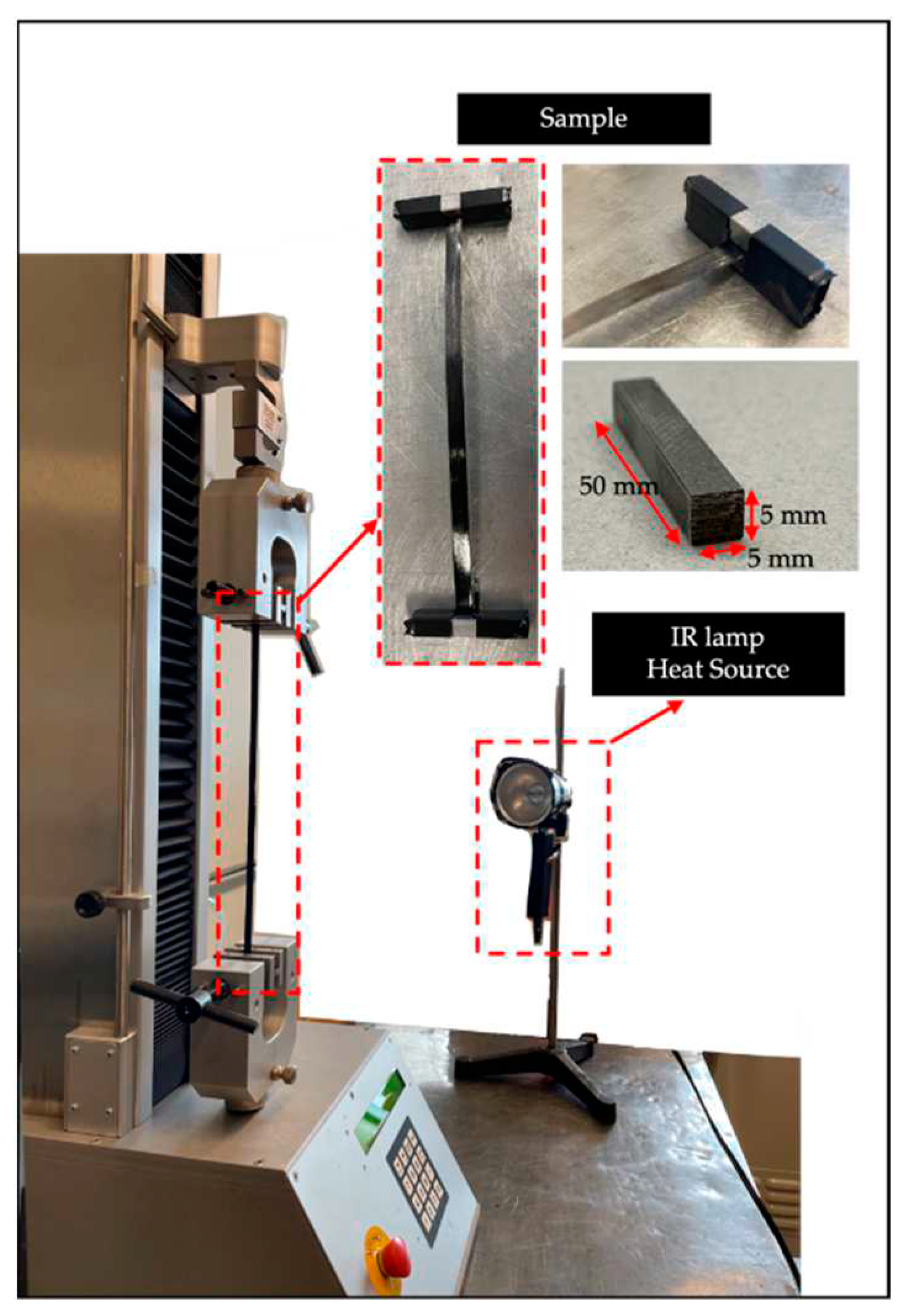
The uniaxial tests were performed using a HOSKIN tensile testing machine in tension mode, equipped with a 1 kN load cell and standard knurled grips, as illustrated in
Figure 1. As the focus of the study was not on sample failure, a higher-rated load cell was not required. To provide heat during the tests, an IR lamp was utilized as a heat source. Additionally, the temperature of the specimen was measured using an infrared camera (FLIR T450c, FLIR, US).
In order to address the issue of slippage caused by the viscous nature of the uncured prepreg, the standard gripping method had to be modified. Several approaches have been developed to prevent slippage in the grips, including rapidly curing the ends of the specimens using heater plates [
10], wrapping the grips in sandpaper to add an extra source of friction in holding the viscous sample [
13], and wrapping the sample ends around the pins [
1]. In this study, a specific gripping method was employed. The ends of the prepreg samples were wrapped around one of the steel rods approximately two times, equivalent to approximately 8 cm of material. The wrapped ends were then pressed against the other rod to create a sandwich-like arrangement. The steel bars used had a length of 50 mm and a cross-section of 5 mm × 5 mm. To ensure proper alignment and application of tensile load in the fiber direction, the samples were first set up and clamped in the lower grip. They were then carefully aligned and secured in the upper grip, taking precautions to avoid any misalignment in the sample setup.
2.2. Tensile test validation
Each sample underwent two testing runs to ensure reliable results. The primary objective of the first run was to establish system stability, validate the gripping technique, and apply a pre-load to the sample. This initial run followed standard tensile testing procedures, gradually increasing the load up to a maximum of 100 N at a displacement rate of 2 mm/min. Once the first run concluded, the specimen was carefully returned to its original position, and the load was removed. After resetting the sample, the second run was conducted, aiming to reach a maximum allowable force of 200 N. The analysis of the tensile behavior encompassed the results obtained from this second tensile test run.
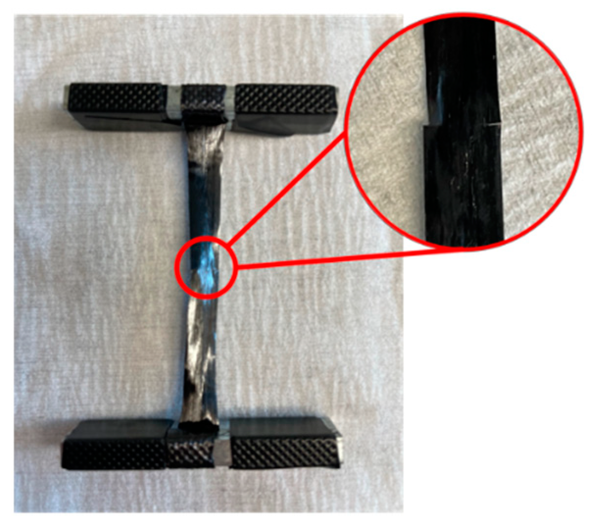
The influence of gauge length on tensile response was investigated to find the best possible gauge length. Tensile tests were conducted at room temperature using samples with varying gauge lengths within the range of 100 to 350 mm. The engineering stress and engineering strain values were computed based on the recorded force and displacement measurements during the experimental procedure. During the tests, it was observed that the outer edges of the sample did not experience tension during the loading process. To ensure the accuracy of the test results, the outer edges were removed by cutting, as depicted in
Figure 2. Furthermore, it was assumed that the contribution of the uncured epoxy to the tensile modulus was insignificantly small. As a result, it was considered that the entirety of the stress was solely exerted on the fibers. This assumption was supported by the equation of the rule of mixtures (equation 1) commonly employed in determining the elastic modulus:
where
Vf and 𝐸
𝑓 are the fiber volume fraction and elastic modulus, 𝐸
𝑚 represents the modulus of the resin, and 𝐸
𝑐 is combined elastic modulus. The Rule of Mixtures is derived from a constant-strain analysis, and it can be used to estimate the upper-bound of the modulus for a composite system. In this study, the fibers possess an elastic modulus (Ef) of 237 GPa, while the matrix has an elastic modulus (Em) of 3 GPa. As a result, with a volume fraction (Vf) of 60%, the lamina exhibits a modulus of 143 GPa. Considering the viscous nature of the matrix, it was justified to assume that the modulus of the epoxy had a negligible contribution to the modulus of the tow. Thus, when calculating the stress within the sample, the width and thickness of the samples were adjusted based on the volume fraction of the fibers.
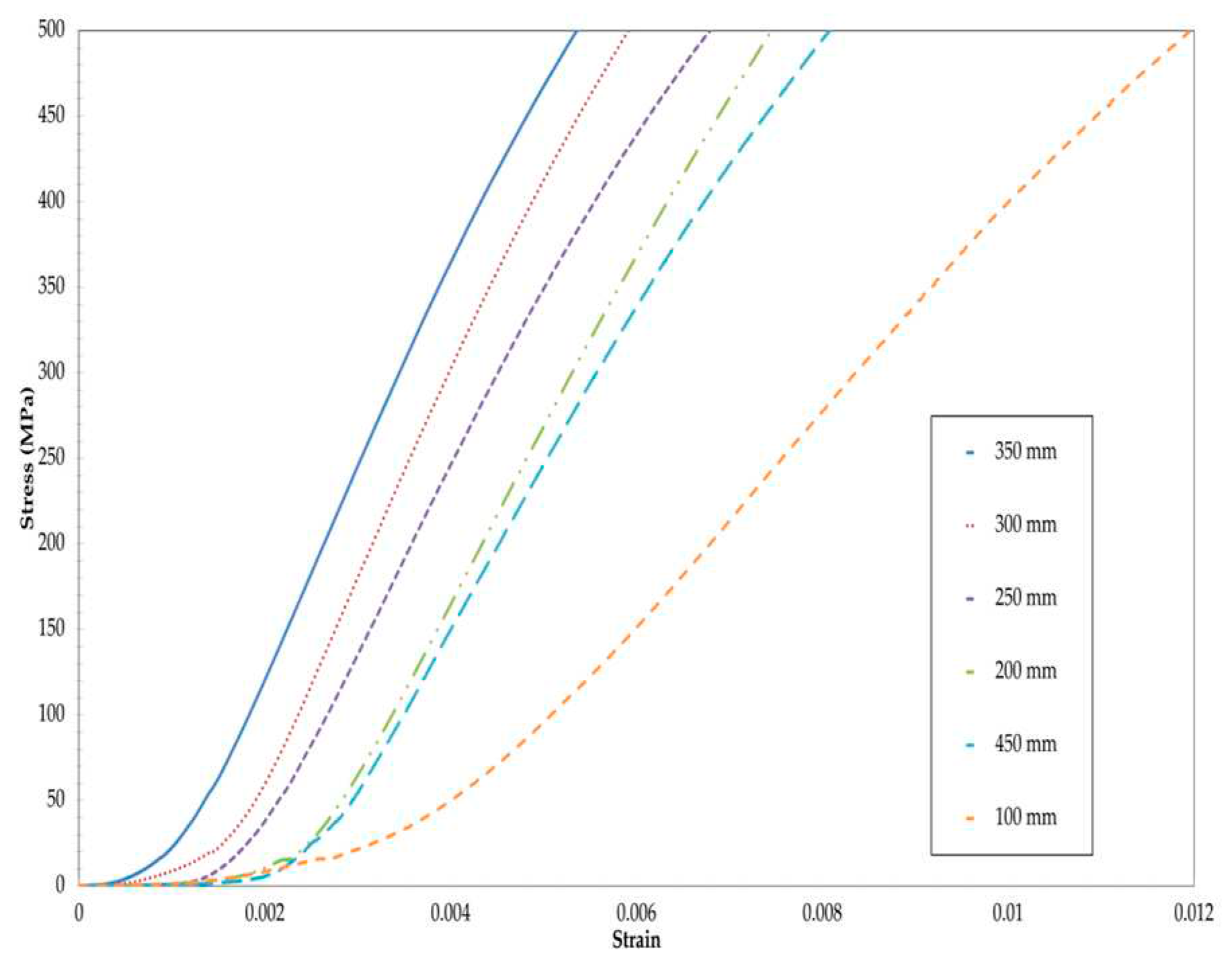
It was anticipated that the impact of slippage would diminish with increasing gauge lengths. As the length of the sample was extended, the linear segments of the stress-strain curves converged to a single slope, as illustrated in
Figure 3. The slopes of the stress-strain curves for longer gauge lengths in the linear region aligned with the expected tensile modulus predicted by the Rule of Mixtures. Since the experimental values closely approached 143 GPa, it was inferred that the influence of slippage was insignificant for specimen lengths equal to or greater than 300 mm. Consequently, tensile tests were performed using a gauge length of 300 mm, employing an average of eight samples.
Table 2 summarizes the moduli for the gauge lengths. However, it was expected that there would be a discrepancy between the modulus values of cured and uncured samples. Cured prepreg experiences the effects of pressure and temperature, which can to some extent correct the waviness in the prepreg. On the other hand, waviness cannot be corrected during uncured tensile testing. Nevertheless, the resulting plots exhibited a linear trend across all samples, indicating that if there were any slippage within the grips, it would have resulted in non-linearity. Therefore, the proposed test method demonstrated good repeatability among the test samples, and the modification made to the grips proved effective in preventing sample slippage.
3. Finite Element Model
This study employed Finite Element Analysis (FEA) to assess the homogenized properties of a prepreg material featuring a periodic microstructure composed of cylindrical fibers arranged in sinusoidal paths. In the existing body of literature [
29,
31,
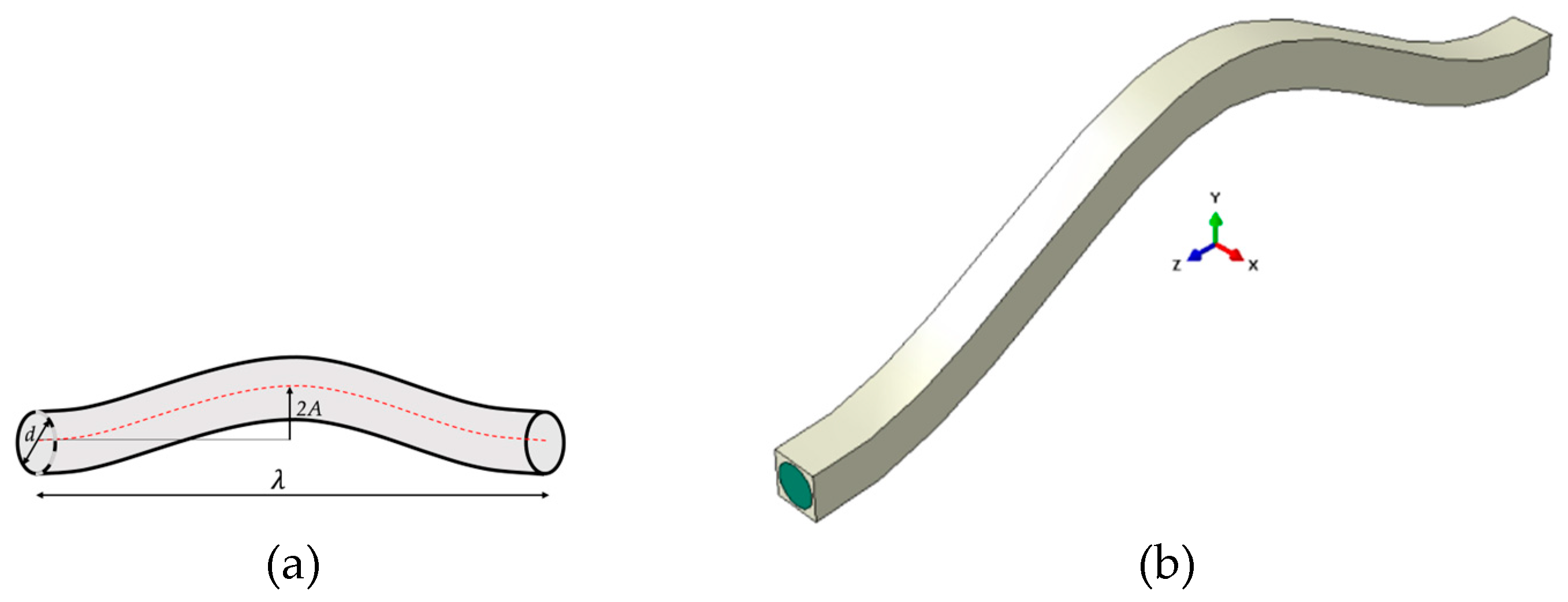
32], analytical and numerical methods have been extensively employed to assess the effective elastic properties of unidirectional composites comprised of elastic matrix and fibers via the utilization of representative volume element (RVE) analysis. In this study, we aim to replicate these approaches to evaluate the aforementioned properties for the prepreg tow with wavy fibers as depicted in
Figure 4. The geometrical parameters under consideration include the wavelength (λ), amplitude (A), and fiber diameter (d). Three different fiber arrangements, namely square, diamond, and hexagonal, were investigated. To represent these arrangements, three Representative Volume Element (RVE) models were developed using the Abaqus/CAE 2022 commercial software. The directions z, x, and y correspond to the longitudinal, transverse within the plane of fiber waviness, and transverse normal to the plane of waviness directions, respectively.
The fiber material was assumed to be isotropic and elastic, characterized by an elastic modulus of 237 GPa and a Poisson's ratio of 0.3. On the other hand, the matrix material was considered to be an isotropic and linear elastic material, with a Young's modulus assigned a value of 3.5 GPa to represent a cured epoxy system. As a result, the prepreg material exhibited orthotropic behavior.
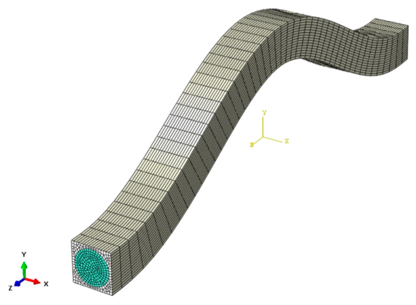
The RVE model was meshed by C3D8R elements as shown in
Figure 5. The core principle of the RVE homogenization method involves numerically evaluating the response of a microscale RVE subjected to simple deformation. It is assumed that the RVE is a representative portion of a periodic material. Therefore, to maintain the periodicity of the RVE's external surfaces during the deformation process, periodic boundary conditions (PBCs) must be applied. This is achieved by pairing opposite faces of the RVE and enforcing a constraint equation:
where 2a
1, 2a
2, 2a
3 are the length of the RVE model in z, x, and y direction respectively and ε
0 is the uniform strain applied on the unit cell of the composite material. Considering the stiffness matrix for an orthotropic material:
The entries in the stiffness matrix C
ij can be determined through a series of tests in which a constant average strain is applied to the homogenized RVE and then the average stress is measured:
where α, β =1… 6. So, the components of the stiffness tensor C are determined by solving six elastic models of the RVE subjected to the PBC by Equation (2), where only one component of the strain is different from zero for each of the six problems, each loading case is listed in
Table 3.
3. Results and Discussion
3.1. Experiment Results from Tensile Test
A total of eight samples were subjected to the testing procedure developed based on the evaluation of the test method. The testing process for each specimen consisted of two separate runs of tensile testing. The first run served to apply a pre-load to the sample, ensuring the stability of the system and verifying proper alignment and setup of the grips. After the completion of the first run, the sample was returned to its initial position, and a few seconds later, the second run of tensile testing was conducted. The results obtained from the second run of tensile testing were included in the analysis of the tensile behavior.
Plots were generated using the average data obtained from the experimental samples. These plots provide insights into the non-linear and final linear stiffness exhibited by the uncured prepreg material.
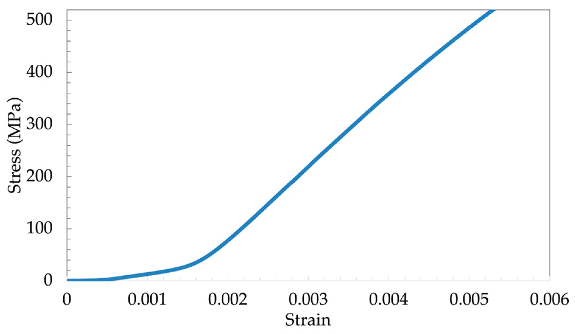
Figure 6 illustrates the stress-strain curve derived from the average results of all the experiments conducted. The findings indicate that the tensile response of the uncured carbon fiber initially exhibited a non-linear behavior, followed by a linear region. Similar observations have been reported in previous studies, where the non-linear region is referred to as the lead-in region of the reduced modulus [
1,
10,
12,
13]. In our prepreg material, the lead-in (non-linear) region of the stress-strain curve extended up to 0.2% strain, after which a linear trend was observed.
A linear trendline fitted to the linear region of the average stress-strain plot (0.2%-0.5% strain) yields a slope of 131, corresponding to an average linear modulus of 131 GPa. This value aligns closely with the linear modulus obtained in
Section 2.2, which was reported as 130 GPa. The consistency in the linear modulus underscores the repeatability of the test method across the sample size. The experimentally determined values for the linear tensile modulus of each individual sample can be found in
Table 4. The average linear tensile modulus of the uncured carbon fiber prepreg tested in this study is approximately 135 GPa with standard deviation of 6 GPa. While this average value provides a general representation, it is important to note that individual samples are expected to exhibit a linear tensile modulus within the range of 130-142 GPa.
The non-linearity region, ranging from 0% to 0.2% strain and ending at a load of approximately 30 N, holds significant importance in AFP & ATL manufacturing processes. These processes typically involve loads that fall within this region of non-linear stiffness. Although it is challenging to directly measure the loads during AFP & ATL, it is expected that the tensile modulus of the uncured prepreg lies within the non-linear region of its stress-strain response. Consequently, modeling the manufacturing process must account for factors such as waviness, misalignment, and the changing modulus within this region.
The experimental findings indicate that the waviness of the fibers plays a pivotal role in influencing the mechanical behavior of the uncured prepreg. The non-linear stress-strain curve arises from the interaction between the fiber waviness and the viscous matrix. The resistance encountered by the fibers as they are pulled through the resin leads to a reduction in stiffness. Additionally, the amplitude of the geometric waveform affects the stiffness as it alters the angle of the fibers, following the principles of classical lamination theory.
According to classical lamination theory, the modulus of composites is directly associated with the orientation of the fibers. Under the application of uniaxial tensile load, the viscous nature of the uncured epoxy matrix allows the fibers to align themselves with the loading direction. As the load and displacement increase, the alignment of the fibers becomes more closely aligned with the 0-degree direction (the direction of the applied load), resulting in a higher modulus. Eventually, as the load and displacement reach a critical point, the majority of the fibers will have their misalignment corrected, leading to a linear tensile response.
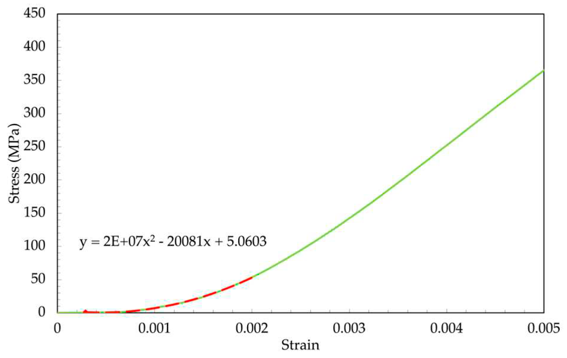
To determine the tensile modulus in the non-linear region, a curve fitting approach was employed. Firstly, the average plot across all samples was considered, and a second-order polynomial was utilized to fit a trendline to the range of 0% to 0.2% strain, as shown in
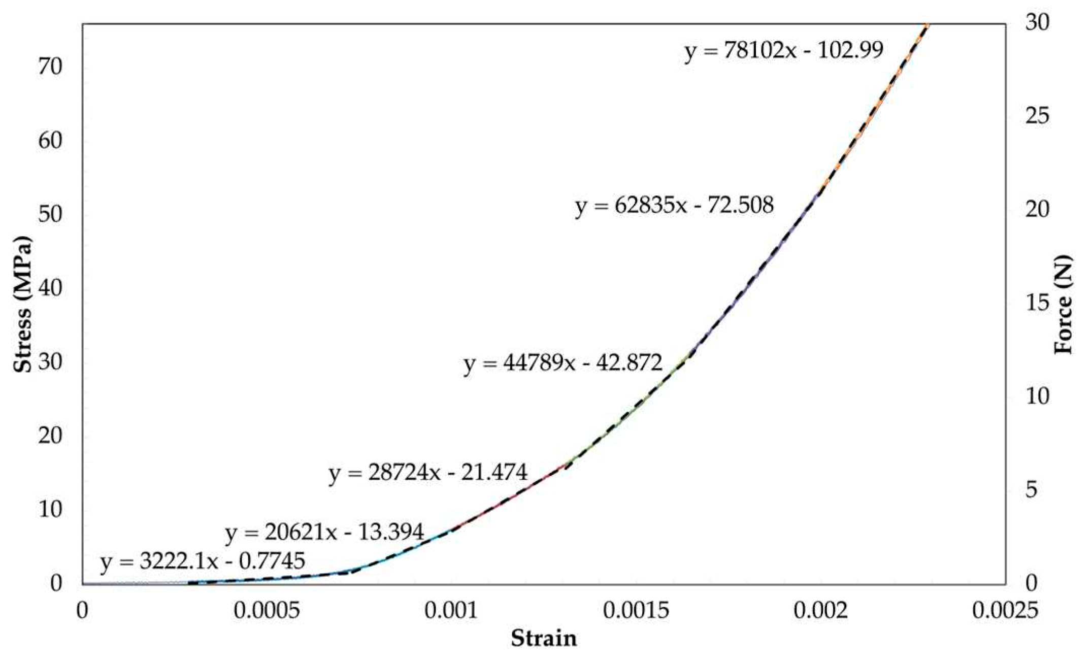
Figure 7. The slope of the trendline was obtained by calculating the first derivative of the polynomial equation, which corresponds to the average tensile modulus exhibited by the uncured prepreg at a specific point within the non-linear region. To gain a clearer understanding of the tensile response in the non-linear region, the curve was divided into smaller sections, as illustrated in
Figure 8. The equations for each trendline are visible on the curve, and the slope of the trendline represents the tensile modulus of the uncured prepreg. Applying these trendlines to each test sample, the average tensile modulus per section was determined in
Table 5.
3.2. Effects of Temperature on the Tensile Behavior
The tensile behavior of the prepreg at room temperature revealed that the presence of waviness in the carbon fibers embedded in the viscous matrix contributed to the occurrence of the non-linear region. Considering the influence of temperature on the mechanical performance of the uncured epoxy matrix, the tensile tests were conducted at elevated temperatures using the same gripping solution as in the room temperature testing. Prior to testing, the samples were thawed at room temperature for 1 hour after being removed from the freezer. The testing procedure involved applying an initial tensile load up to a maximum of 100 N, followed by returning the sample to its initial condition before conducting a second tensile test at the elevated temperature.
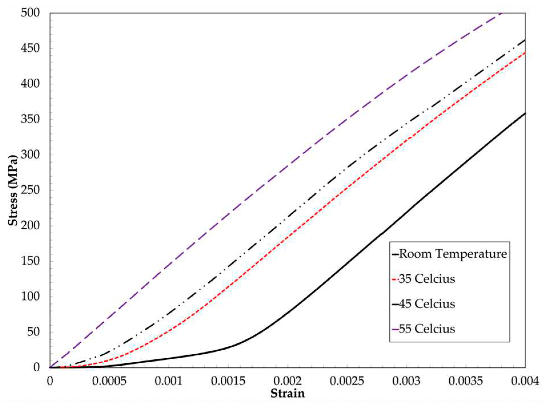
The results obtained from the tensile tests demonstrated that, at different temperatures, the prepreg samples exhibited a consistent slope in the linear region, confirming the assumption that the epoxy matrix’s contribution to stiffness in this region is negligible,
Figure 9. As concluded in
Section 3.1, the linear stiffness of the UD carbon epoxy prepreg is closely aligned with that of the fibers, and since the tensile modulus of the fibers remains independent of temperature, it can be inferred that the linear stiffness of the prepreg is unaffected by temperature variations. Furthermore, at higher temperatures, the viscosity of the epoxy matrix decreases, leading to reduced resistance to the movement of the prepreg. Despite this, on average, the fibers still need to undergo the same distance to rectify the waviness within the sample (straighten up). With less resistance to this movement, the stiffness plot is shifted upwards. The observed temperature effects on the reduction of the lead-in region during the tensile test align with previous findings on carbon epoxy prepreg [
10].
3.3. Finite element model
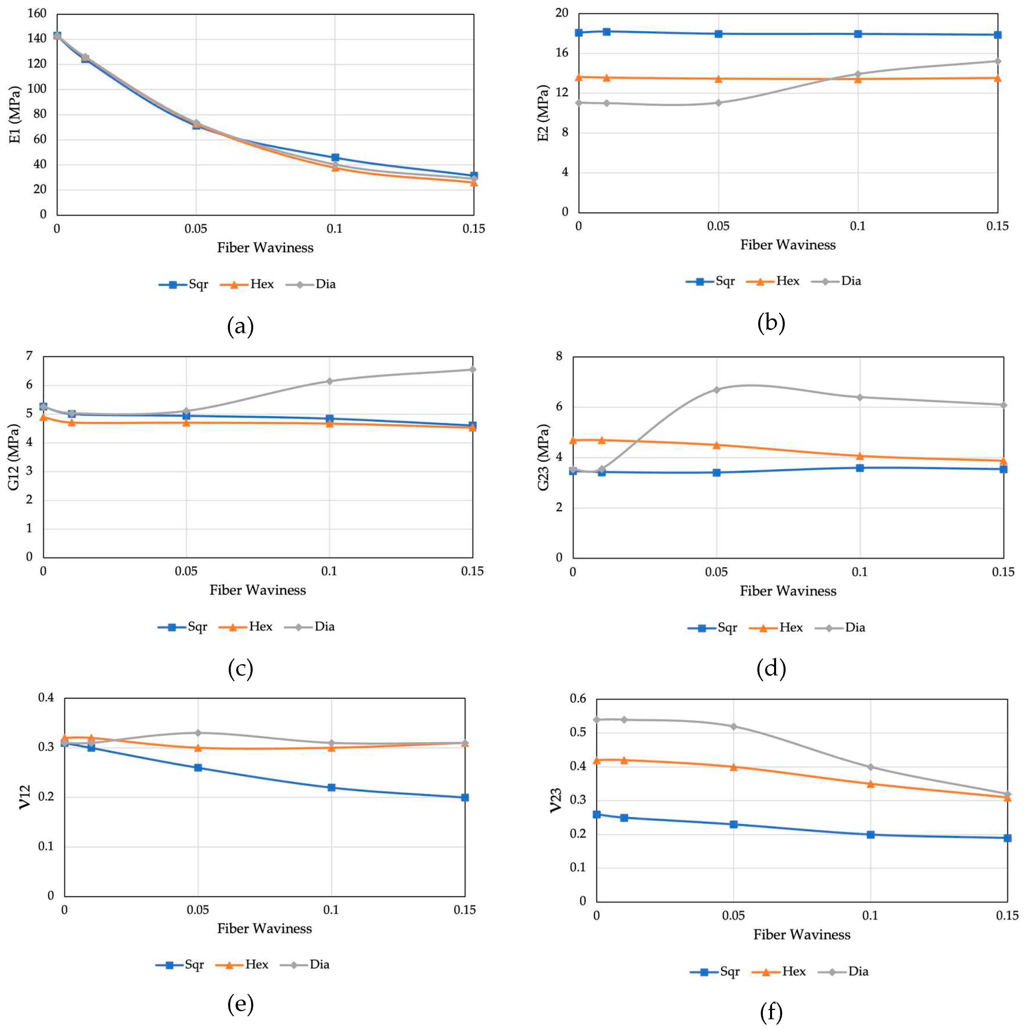
This section focuses on the computation of homogenized mechanical properties for composite materials with wavy fibers. The objective is to examine the impact of fiber waviness on prepreg properties. To achieve this, we analyze three Representative Volume Element (RVE) models associated with distinct fiber arrays: hexagonal, diamond, and square. These models are investigated within a waviness ratio range of 0 to 0.15, and the resulting homogenized stiffness matrix parameters are computed. The graphical representation of these parameters can be found in
Figure 10. The results for the straight fiber agree with the [
10,
12,
29,
31] showing a slight difference in the three fiber arrangement models . For effective Young’s modulus E
1, longitudinal Poisson’s ratio n
12,
and longitudinal shear modulus G
12, the values predicted by the three models are all in excellent agreement with that noted by random fiber distribution, which indicates that fiber arrangement has a negligible effect on these three effective longitudinal material properties. In contrast, for effective transverse material properties such as transverse Young’s modulus E
2, transverse Poisson’s ratio ν
23, and shear modulus G
23 the values calculated by the hexagonal array agree with the random fiber distribution confirming that the random microstructure is well approximated by the hexagonal microstructure.
At lower levels of fiber waviness, there is a high level of agreement in the matrix stiffness parameters. However, as the waviness value exceeds 0.05, deviations start to emerge. These deviations are attributed to variations in the numerical discretization within each fiber array [
23,
27]. In summary, it can be inferred that fiber waviness has a significant impact on the longitudinal Young’s modulus but has a negligible effect on other properties. As the degree of fiber waviness increases, the effective Young’s modulus (E1) decreases, as observed in the results of the uniaxial tensile tests outlined in
Section 3.2.
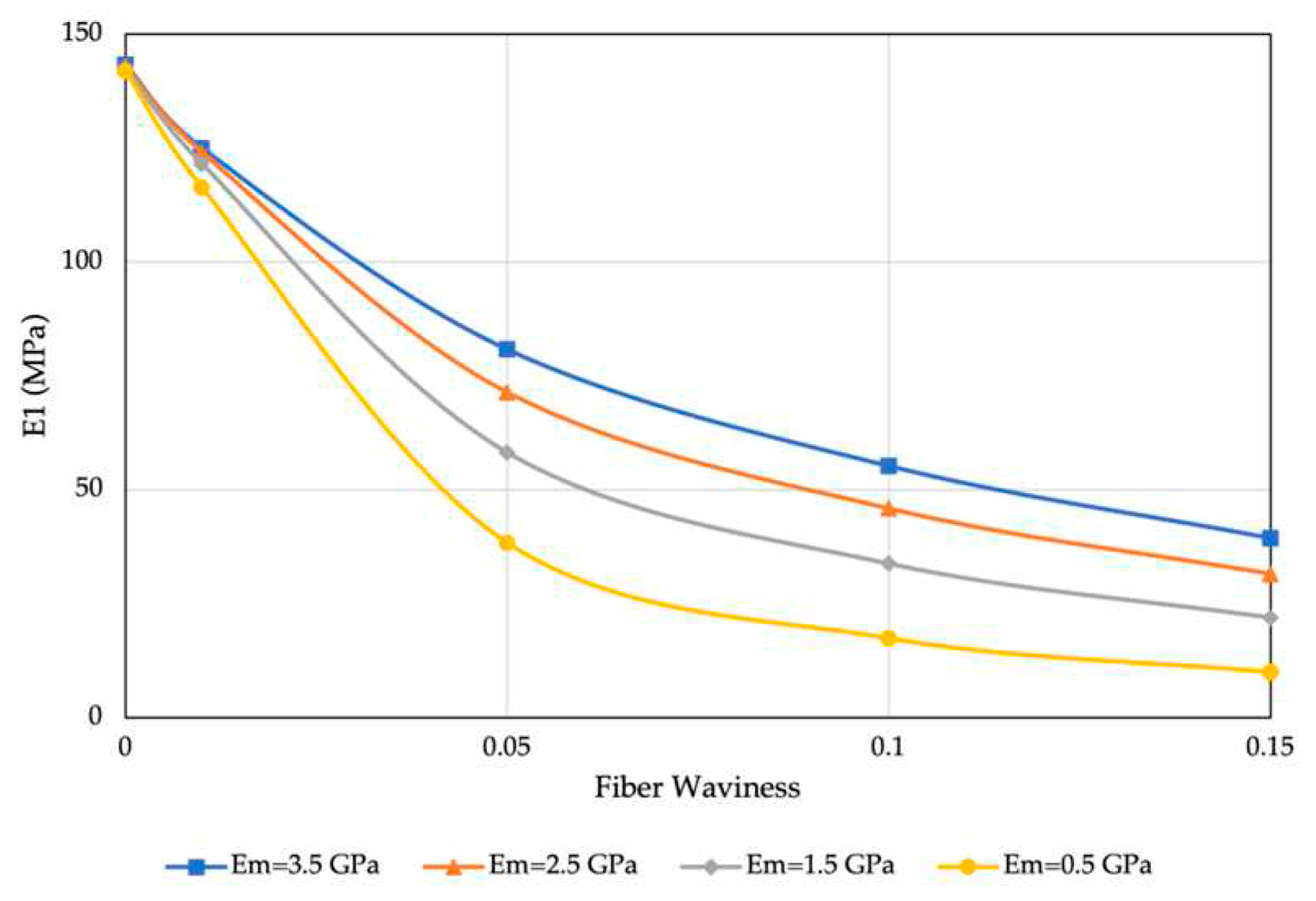
In accordance with previous discussions, the matrix and fibers were regarded as materials with linear elastic properties. To facilitate the examination of the temperature’s impact on the behavior of the waved fiber, the Representative Volume Element (RVE) model was employed, considering various matrix modulus values. This approach was chosen since temperature primarily affects the stiffness of the matrix, rather than that of the fibers.
Figure 11 provides insights into the behavior of the RVE model with square array at different temperatures, particularly in relation to the matrix stiffness. The figure indicates that as the temperature increases, resulting in lower matrix stiffness values, the reduction in fiber waviness leads to a more rapid change in the E
1 values. This observation aligns well with the experimental results discussed in
Section 3.2, further confirming the validity and applicability of the proposed RVE model. These results highlight the significance of considering temperature effects on composite materials, specifically the influence of matrix stiffness, and emphasize the importance of accurately modeling and characterizing such phenomena for a comprehensive understanding of the material behavior.
4. Conclusion
In this paper, the tensile behavior of unidirectional carbon epoxy prepreg was studied experimentally and numerically. The testing procedure involved conducting two separate runs of tensile testing on eight samples to evaluate their tensile behavior. The stress-strain curves obtained from the second run of testing were analyzed to assess the non-linear and final linear stiffness of the uncured prepreg material. The results indicated that the material initially exhibited a non-linear behavior followed by a linear region, consistent with previous studies. The linear modulus obtained from the average stress-strain plot was closely aligned with the linear modulus of the fiber. Moreover, it was shown that the non-linear region, crucial in AFP & ATL manufacturing processes, typically involves loads falling within the 0% to 0.2% strain range. The tensile modulus of the uncured prepreg is expected to lie within this non-linear region. Experimental findings highlight the interaction between fiber waviness and the viscous matrix, leading to a reduction in stiffness, while the amplitude of the geometric waveform affects stiffness through alterations in fiber angle. The tensile tests conducted on the prepreg samples at different temperatures revealed a consistent slope in the linear region, indicating that the stiffness contribution of the epoxy matrix is negligible in this range. The linear stiffness of the UD carbon epoxy prepreg closely follows that of the fibers and remains unaffected by temperature variations. At higher temperatures, the decreased viscosity of the epoxy matrix reduces resistance to movement, resulting in an upward shift of the stiffness plot in the non-linear region. The RVE model also showed that the fiber waviness substantially influences effective longitudinal material properties. Furthermore, it was demonstrated that higher temperatures and lower matrix stiffness values lead to a more rapid change in E1 values as fiber waviness decreases, consistent with experimental findings and emphasizing the importance of accurately modeling temperature effects on composite materials.
Acknowledgments
The authors gratefully acknowledge financial support from Natural Science and Engineering Research Council of Canada (NSERC) through Discovery Grant.
References
- L. M. Dangora, C. L. M. Dangora, C. Mitchell, K. D. White, J. A. Sherwood, and J. C. Parker, “Characterization of temperature-dependent tensile and flexural rigidities of a cross-ply thermoplastic lamina with implementation into a forming model,” Int. J. Mater. Form., vol. 11, no. 1, pp. 43–52, Jan. 2018. [Google Scholar] [CrossRef]
- A. Rashidi, H. Montazerian, K. Yesilcimen, and A. S. Milani, “Experimental characterization of the inter-ply shear behavior of dry and prepreg woven fabrics: Significance of mixed lubrication mode during thermoset composites processing,” Compos. Part Appl. Sci. Manuf., vol. 129, p. 105725, Feb. 2020. [CrossRef]
- M. Kheradpisheh and M. Hojjati, “Wrinkle Formation and Initial Defect Sensitivity of Steered Tow in Automated Fiber Placement,” J. Compos. Sci., vol. 5, no. 11, Art. no. 11, Nov. 2021. [CrossRef]
- A. Brasington, C. Sacco, J. Halbritter, R. Wehbe, and R. Harik, “Automated fiber placement: A review of history, current technologies, and future paths forward,” Compos. Part C Open Access, vol. 6, p. 100182, Oct. 2021. [CrossRef]
- M. R. Garnich and G. Karami, “Localized Fiber Waviness and Implications for Failure in Unidirectional Composites,” J. Compos. Mater., vol. 39, no. 14, pp. 1225–1245, Jul. 2005. [CrossRef]
- H. Alshahrani and M. Hojjati, “A theoretical model with experimental verification for bending stiffness of thermosetting prepreg during forming process,” Compos. Struct., vol. 166, pp. 136–145, Apr. 2017. [CrossRef]
- H. Alshahrani and M. Hojjati, “Bending behavior of multilayered textile composite prepregs: Experiment and finite element modeling,” Mater. Des., vol. 124, pp. 211–224, Jun. 2017. [CrossRef]
- Le, S. Nimbalkar, N. Zobeiry, and S. Malek, “An efficient multi-scale approach for viscoelastic analysis of woven composites under bending,” Compos. Struct., vol. 292, p. 115698, Jul. 2022. [Google Scholar] [CrossRef]
- S. Rajan, M. A. S. Rajan, M. A. Sutton, R. Wehbe, Z. Gurdal, A. Kidane, and I. Emri, “Characterization of viscoelastic bending stiffness of uncured carbon-epoxy prepreg slit tape,” Compos. Struct., vol. 275, p. 114295, Nov. 2021. [Google Scholar] [CrossRef]
- K. Potter, C. K. Potter, C. Langer, B. Hodgkiss, and S. Lamb, “Sources of variability in uncured aerospace grade unidirectional carbon fibre epoxy preimpregnate,” Compos. Part Appl. Sci. Manuf., vol. 38, no. 3, pp. 905–916, Mar. 2007. [Google Scholar] [CrossRef]
- K. Potter, B. K. Potter, B. Khan, M. Wisnom, T. Bell, and J. Stevens, “Variability, fibre waviness and misalignment in the determination of the properties of composite materials and structures,” Compos. Part Appl. Sci. Manuf., vol. 39, no. 9, pp. 1343–1354, Sep. 2008. [Google Scholar] [CrossRef]
- W. Zhang et al., “Experimental methods to characterize the woven composite prepreg behavior during the preforming process,” Ford Motor Company, Detroit, MI (United States), Sep. 2016. Accessed: Nov. 29, 2021. [Online]. Available: https://www.osti.gov/biblio/1431017-experimental-methods-characterize-wovencomposite-prepreg-behavior-during-preforming-process.
- D. Ferré Sentis et al., “Tensile behaviour of uncured sheet moulding compounds: Rheology and flow-induced microstructures,” Compos. Part Appl. Sci. Manuf., vol. 101, pp. 459–470, Oct. 2017. [CrossRef]
- M.-G. Han and S.-H. Chang, “Draping simulations of carbon/epoxy fabric prepregs using a non-orthogonal constitutive model considering bending behavior,” Compos. Part Appl. Sci. Manuf., vol. 148, p. 106483, Sep. 2021. [CrossRef]
- X.-Y. Zhou, S.-Y. Qian, N.-W. Wang, W. Xiong, and W.-Q. Wu, “A review on stochastic multiscale analysis for FRP composite structures,” Compos. Struct., vol. 284, p. 115132, Mar. 2022. [CrossRef]
- B. Erice and D. Thomson, “Modelling the Non-linear fibre and matrix dominated compressive behaviour in unidirectional Fibre-reinforced composites,” Compos. Struct., vol. 304, p. 116396, Jan. 2023. [CrossRef]
- N. Safdar, B. N. Safdar, B. Daum, and R. Rolfes, “A numerical prediction of failure probability under combined compression-shear loading for unidirectional fiber reinforced composites,” Mech. Mater., vol. 171, p. 104352, Aug. 2022. [Google Scholar] [CrossRef]
- S. W. Yurgartis, “Measurement of small angle fiber misalignments in continuous fiber composites,” Compos. Sci. Technol., vol. 30, no. 4, pp. 279–293, Jan. 1987. [CrossRef]
- L. Stewart and A. Poursartip, “Characterization of fibre alignment in as-received aerospace grade unidirectional prepreg,” Compos. Part Appl. Sci. Manuf., vol. 112, pp. 239–249, Sep. 2018. [CrossRef]
- D. Wilhelmsson and L. Asp, “A high resolution method for characterisation of fibre misalignment angles in composites,” Compos. Sci. Technol., vol. 165, pp. 214–221, 2018. 2018. [CrossRef]
- P. J. Joyce, D. Kugler, and T. J. Moon, “A Technique for Characterizing Process-Induced Fiber Waviness in Unidirectional Composite Laminates-Using Optical Microscopy,” J. Compos. Mater., vol. 31, no. 17, pp. 1694–1727, Sep. 1997. [CrossRef]
- M. Herráez et al., “Computational micromechanics evaluation of the effect of fibre shape on the transverse strength of unidirectional composites: An approach to virtual materials design,” Compos. Part Appl. Sci. Manuf., vol. 91, pp. 484–492, Dec. 2016. [CrossRef]
- D. Kuksenko, H. J. Böhm, and B. Drach, “Effect of micromechanical parameters of composites with wavy fibers on their effective response under large deformations,” Adv. Eng. Softw., vol. 121, pp. 206–222, Jul. 2018. [CrossRef]
- M. R. Garnich and G. Karami, “Finite Element Micromechanics for Stiffness and Strength of Wavy Fiber Composites,” J. Compos. Mater., vol. 38, no. 4, pp. 273–292, Feb. 2004. [CrossRef]
- A. Chanda, S. K. Sinha, and N. V. Datla, “The influence of fiber alignment, structure and concentration on mechanical behavior of carbon nanofiber/epoxy composites: Experimental and numerical study. Polym. Compos., vol. 42, no. 3, pp. 1155–1173, 2021. 42(3), 1155–1173. [CrossRef]
- M. P. Alves, C. A. Cimini Junior, and S. K. Ha, “Fiber waviness and its effect on the mechanical performance of fiber reinforced polymer composites: An enhanced review,” Compos. Part Appl. Sci. Manuf., vol. 149, p. 106526, Oct. 2021. [CrossRef]
- G. Karami and M. Garnich, “Effective moduli and failure considerations for composites with periodic fiber waviness,” Compos. Struct., vol. 67, no. 4, pp. 461–475, Mar. 2005. [CrossRef]
- G. Karami and M. Garnich, “Micromechanical study of thermoelastic behavior of composites with periodic fiber waviness,” Compos. Part B Eng., vol. 36, no. 3, pp. 241–248, Apr. 2005. [CrossRef]
- N. An, Q. Jia, H. Jin, X. Ma, and J. Zhou, “Multiscale modeling of viscoelastic behavior of unidirectional composite laminates and deployable structures,” Mater. Des., vol. 219, p. 110754, Jul. 2022. [CrossRef]
- “CYCOM 977-2,” Solvay. https://www.solvay.com/en/product/cycom-977-2 (accessed Nov. 29, 2021).
- L. Riaño and Y. Joliff, “An AbaqusTM plug-in for the geometry generation of Representative Volume Elements with randomly distributed fibers and interphases,” Compos. Struct., vol. 209, pp. 644–651, Feb. 2019. [CrossRef]
- S. L. Omairey, P. D. Dunning, and S. Sriramula, “Development of an ABAQUS plugin tool for periodic RVE homogenisation,” Eng. Comput., vol. 35, no. 2, pp. 567–577, Apr. 2019. [CrossRef]
|
Disclaimer/Publisher’s Note: The statements, opinions and data contained in all publications are solely those of the individual author(s) and contributor(s) and not of MDPI and/or the editor(s). MDPI and/or the editor(s) disclaim responsibility for any injury to people or property resulting from any ideas, methods, instructions or products referred to in the content. |
© 2023 by the authors. Licensee MDPI, Basel, Switzerland. This article is an open access article distributed under the terms and conditions of the Creative Commons Attribution (CC BY) license (http://creativecommons.org/licenses/by/4.0/).
