Preprint
Article

A Novel Hybrid CSP-PV Power Plant Based on Brayton Supercritical CO2 Thermal Machines

Altmetrics

Downloads

131

Views

61

Comments

0

A peer-reviewed article of this preprint also exists.

Submitted:

27 June 2023

Posted:

28 June 2023

You are already at the latest version

Alerts
Abstract
A novel hybrid CSP-PV power plant is presented. Instead of the integration used in current hybrid power plants, where part of the PV production is charged into the thermal energy storage system through electrical resistors, the proposed system integrates both PV and thermal solar fields using a high-temperature heat pump. Both the heat pump and the heat engine are based on Brayton supercritical CO2 thermodynamic cycles. Such integration allows for charging the molten salts storage as if a central tower receiver field supplied the thermal energy, whereas parabolic trough collectors are employed. Unlike conventional hybrid plants, where the storage of PV production leads to a decrease in power injected into the grid throughout the day, the power injected by the proposed system remains constant. The heat engine efficiency is 44.4%, and the COP is 2.32. The LCOE for a 50 MWe plant with up to 12 hours of storage capacity is 171 $/MWh, which is lower than that of existing CSP power plants with comparable performance. Although the cost is higher compared to a PV plant with batteries, this hybrid system offers two significant advantages: it eliminates the consumption of critical raw materials in batteries, and all the electricity produced comes from a synchronous machine.
Keywords: 
Subject: Engineering  -   Energy and Fuel Technology

1. Introduction

To stay on track to limit the global temperature rise to 1.5°C above pre-industrial levels, the world needs a significant increase in renewable energy. By the end of 2022, renewables comprised 40% of the global installed power capacity. This means the largest increase in renewable energy capacity to date, adding nearly 295 GW and boosting the renewable energy stock by 9.6%, with solar energy contributing almost two-thirds [1].
Integrating large-scale storage systems becomes crucial to ensure a stable and reliable energy supply as the world seeks to reduce carbon emissions and move towards cleaner energy sources. Storage systems enable the capture and efficient use of excess energy generated by intermittent renewable sources, such as photovoltaic (PV) and wind power. In concentrated solar power (CSP) systems, thermal energy storage (TES) technology is proven particularly effective in converting intermittent solar power into a manageable source. Hybridizing CSP technology with other energy sources enables even better performance by balancing supply and demand, reducing intermittent generation, and lowering the cost of electricity. Thus, integrating storage systems in renewable energy plants, such as hybrid CSP plants, is vital in creating a sustainable and resilient energy infrastructure, supporting decarbonization goals and providing a cost-effective, reliable and manageable energy source.
A review of hybrid concentrated solar thermal energy systems is shown in [2]. There are several opportunities to harness solar energy in combination with coal, natural gas and biofuels through hybridization. These fuels offer reliability, manageability and flexibility, although they are not entirely renewable, with the exception of biofuels. On the one hand, combinations of geothermal, wind energy and solar photovoltaic (PV) panels with concentrating solar power systems are fully renewable energy sources. However, they lack certain benefits associated with fossil fuels. The low source temperatures limit the efficiency of CSP-geothermal hybrid designs. On the other hand, the combination of wind energy and CSP and the integration of photovoltaic/thermal systems lack manageability, making their hybridization with thermal energy storage (TES) systems particularly interesting. In this way, TES can be harnessed to improve management and maximize the performance of these hybrid systems.
CSP has traditionally been considered more suitable than PV for baseload generation because thermal storage is more economical than battery storage. However, the solar fields used in CSP technology are usually relatively expensive. Besides, PV plants without storage supply electricity at a much lower cost than CSP plants of comparable capacity without storage. Therefore, the integration of these two technologies is presented as an attractive approach to achieve baseload solar generation with an affordable levelized cost of electricity (LCOE).
Hybrid plants that combine CSP and PV power can be classified into two main categories: non-compact plants and compact plants [3]. In the case of non-compact plants, hybridization occurs at the grid connection point. Both solar thermal and photovoltaic power generation are carried out in parallel, and the solar thermal plant uses thermal storage to supply power during periods of low solar radiation, such as at night or on cloudy days. Compact hybrid plants integrate both technologies in a single installation. Currently, PV technology captures approximately 15% of solar radiation, while the rest is dissipated as waste heat, as PV cells need cooling to maintain their performance. CSP-PV hybridization in a compact configuration allows this residual thermal energy to be harnessed. Another way to hybridize CSP and PV technologies is to convert the excess electrical output of the PV panels into thermal energy using an electric heater. This thermal energy can be recovered and stored in a TES for its integration into the power cycle to stabilize the grid connection.
The optimal design of highly integrated CSP-PV power plants was addressed in [4]. A comparison was made between grid-level integration and the inclusion of electric heaters to convert excess PV electricity into heat by storing it in the CSP. For this, a Mixed Integer Linear Program (MILP) was used that considers both design and operational variables was used, taking into account nonlinear effects. The results concluded that the hybrid CSP-PV technology achieved a lower cost of electricity for dispatch levels above 50% and that designs with electric heaters had a 3.6% to 10% lower LCOE compared to grid integration. Regarding the potential for integrating hybrid renewable energy sources into the Qatar power grid, a possible increase of the share of renewable energy sources in electricity production by up to 80% was demonstrated in [5]. The optimal deployment cases of wind, photovoltaic, and concentrated solar power with storage technologies presented a share of 28.3%, 23.4%, and 38.2%, respectively, in electricity production. The economic simulation of the market showed that the total annual cost of some scenarios with renewable energy integration was lower than that of the reference case currently implemented in the country. In [6], it was shown that the hybridization of CSP plants with PV systems could significantly increase the overall plant capacity factor, which contributes to achieving a fully dispatchable solar electricity production system. The study found that CSP-PV plants can achieve capacity factors of 80% or more while reducing the size of the CSP solar field. This was achieved while maintaining a high-capacity factor and reducing the LCOE in the range of 4% to 7% for plants with parabolic trough collectors (PTC) technology and between 1.5% and 4% for plants with central receiver system (CRS) technology. In addition, a reduction in solar field size of approximately 40% was observed for PTC hybrid plants and 30% for CRS hybrid plants. In a similar analysis, in South Africa [7], capacity factors of up to 90% were obtained, with an LCOE of 133-157 $/MWh. In [8], typical capacity factors for intermittent renewable energy sources were revealed to rely on the 20% to 40% range. However, the Solar Reserve's Crescent Dunes project achieved a capacity factor of over 80%, and when combined with PV systems, the capacity factor raised to approximately 90%. In [9], a methodology for designing and sizing hybrid CSP-PV plants was described using a transient simulation model coupled with an evolutionary optimization algorithm. The results showed that the capacity factor reached values above 85%, and the LCOE was lower than stand-alone CSP plants. In [10], a case study that calculates the LCOE for a hybrid CSP-PV plant at the Atacama Solar Platform was presented. The objective was to evaluate new options for continuous power delivery. The results indicated that CSP-PV plants are a feasible option that can contribute to the continuous delivery of sustainable electricity. Two LCOE scenarios, based on IEA studies, were evaluated between 2014 and 2050, obtaining values of 146.9 and 85.7 $/MWh and 138.8 and 77.4 $/MWh, respectively. The integration of CSP-PV plants in two Saudi Arabian cities, Riyadh and Tabuk, was analyzed in [11]. By setting a capacity factor of 79%, it was found that a solar multiple of 6 in Riyadh and 3.5 in Tabuk was required for a single solar plant. However, with the introduction of the hybrid concept, the solar multiple was significantly reduced. It ranged from 2.9 to 3 in Riyadh and from 1.78 to 1.85.in Tabuk
A review of advanced power cycles to improve efficiency and reduce costs was carried out in [12]. It was mentioned that subcritical steam turbines are a developed option, but more agility and flexibility in their operation are required. On the contrary, supercritical steam turbines are considered interesting but are generally too large for existing solar towers. Closed Brayton cycles with supercritical CO2 (S-CO2) are in the early stages of development but offer the promise of high efficiency at reasonable temperatures and in various capacities, with the prospect of significantly reduced costs. In [13], different supercritical CO2 power cycle configurations in a hybrid CSP-PV plant with salt storage were analyzed. The scalability of the plant was investigated, obtaining a LCOE below 66 €/MWh and capacity factors above 70% for a capacity of 100 MWe. In locations with high solar irradiation, a capacity factor of 85% and a LCOE of 46 €/MWh was achieved. In addition, no significant differences in terms of the S-CO2 power cycle configuration were observed. In [14], a method for optimizing the design of a central tower concentrating solar power (CSP-CT) with a supercritical CO2 Brayton cycle was proposed. The optimization considered fluctuating solar irradiation, ambient temperature, and various power demand scenarios based on the system’s off-design performance throughout one year. A multi-objective optimization algorithm obtained a 6.38% improvement in the maximum load cover factor under stable power demand conditions. Additionally, the LCOE was reduced by 5.62% with a load cover factor of 0.9. A hybrid CSP-PV-wind plant based on the S-CO2 Brayton cycle was proposed for different load demand scenarios [15]. It was proved that the load demand scenarios significantly impact load matching and economic performance. The system can meet more than 90% of the annual load demand. The LCOE reached 216.9 $/MWh for the load following scenario, being 32.1% higher than in stable production scenarios.
Hybridization of CSP and PV systems can include thermal energy storage and battery energy storage systems (BESS) to offer cost-competitive renewable energy and load capacity. It was found that a CSP-PV plant with TES and BESS increased the capacity factor reaching values above 85% [16]. However, a significant reduction in battery bank cost (on the order of 60-90%) was required to achieve significant savings. In current scenarios, a CSP-PV plant with TES presents better economics and reliability compared to a system with BESS [17]. However, in promising future scenarios focused on cost reduction (around 60 $/kWh), the advantages of batteries become evident, and a PV plant with batteries shows a higher competitiveness than a plant with TES. This was also discussed in [18]. Different scenarios were explored in [19] to identify the dominant technology in a hybrid solar power plant providing sustainable and programmable energy by 2050. It was concluded that CSP with TES is currently the most affordable technology. Still, a shift towards PV with BESS is expected, mainly due to both systems' significant reduction in costs.
The impact of supply strategies on optimal solar power plant design configurations is crucial for cost and supply assurance. A multi-objective optimization study was conducted for CSP-PV plants with TES and BESS in [20]. It was found that a baseload supply strategy resulted in the lowest LCOE, while the supply strategies during the evening and night hours had the highest LCOE. It was also concluded that PV-BESS plants were the most competitive for daytime and evening supply, while hybrid CSP-PV plants were ideal for long-duration storage applications. Another integration approach was presented in [21], in which the plants were not coupled, but the surplus PV energy was used to store thermal energy. It was found that this can cover up to 67% of the electricity needed for a Mediterranean community and more than 90% of a constant electrical load in locations with low seasonal variation of total solar radiation, such as a semi-arid site in sub-Saharan Africa. However, this increased the LCOE from 50 €/MWh (PV only, no storage) to 90-110 €/MWh.
The design of hybrid solar power plants requires a delicate balance between financial and technical performance considerations. This task is further complicated by the dependence on a broader set of parameters compared to conventional plants, as well as the integration of thermal energy storage. A two-stage multi-objective optimization framework combining linear programming and genetic algorithms was developed for the Atacama-1 hybrid solar power plant in [22], demonstrating the importance of balancing financial and technical tradeoffs. A 5.6% decrease in LCOE was achieved by hybridizing the CSP plant with a PV power plant. A CSP-PV hybrid plant was optimized in [23] using the butterfly algorithm, obtaining that the TES of CSP with 6 hours can achieve stable and continuous power output and that there is a 4.2% increase in power output and a 10.4% reduction in system operation cost. A hybrid CSP-PV power plant with an immersion heater was modeled in [24], and predictive control using linear programming was used for storage strategies in a scenario with real weather data and different tariffs. It was concluded that, compared to heuristic state optimization, a 14% increase in revenue was achieved using a predictive control strategy. It was also shown that the storage strategy affects the achievable plant output and, more significantly, the system sizing and configuration. In [25], a new algorithm was proposed to solve the optimal sizing problem of hybrid systems with TES and BESS storage and production (CSP-PV-wind), minimizing the LCOE while guaranteeing load supply. A LCOE of 180 $/MWh was obtained with a loss of power supply probability (LPSP) of 0% and specific contributions from each generation type. In reference to the model of the plants, in [26], it was stated that control procedures captured with time intervals of 1 to 5 minutes provide a more accurate representation, while a low temporal resolution results in the loss of information on variability effects (using data from 5 to 60 minutes leads to an overestimation of annual totals by 2-6%).
It is also possible to use CSP-PV hybridization in isolated microgrids. PV was combined to cover electricity needs during the day and CSP to supply power during periods of low solar radiation in [27]. The LCOE was found to be 524 $/MWh, only 2% higher than the PV-Battery system. However, for communities with a capacity above 500 kW, the LCOE can be reduced by 26% to 370 $/MWh. In addition to CSP-PV hybridization, it is also possible to include other technologies. A techno-economic analysis of a 100 MW CSP-PV-Multiple Effect Distillation plant was performed in [28]. It was found that this configuration reduces the capacity factor by 7.6% compared to a CSP-PV plant but represents an interesting option for desert areas where mines can be found.
This paper presents a novel integration scheme for combining PV and CSP (based on PTC solar field technology). In this scheme, both solar resources work synchronously, supplying low-temperature heat (PTC) and power (PV) to a novel high-temperature heat pump. This heat pump delivers high-temperature heat to the power cycle (heat engine) as it would have been produced by a central receiver system with heliostats instead a parabolic trough collectors field. To ensure system dispatchability, a two-tank molten salts TES is positioned between the thermal output of the heat pump and the power cycle. The integration through a heat pump instead of electrical resistors allows to recover all the power supplied by the PV, enhancing the thermal supply from the PTC. The core component of this integrated system is a heat pump based on a reverse Brayton cycle using supercritical CO2 as the working fluid. The nearly ideal gas behavior of the fluid in the working zone, along with using a turbocompressor instead of a volumetric compressor, enables the system to achieve the high temperatures required in the molten salt circuits. A recompression Brayton supercritical CO2 cycle is proposed for the heat engine, resulting in high efficiencies. In both cycles, the heat exchangers connected to the high-temperature reservoir are positioned within the low-pressure stream. This arrangement allows for the use of heat exchangers with enough size to avoid clogging issues with the molten salt.

2. Methodology

2.1. Concept

Figure 1a shows a standard hybridization scheme between PV and CSP systems [29]. The key idea is to maximize power generation and reduce the LCOE by covering a significant portion of the day. To achieve this, the PV plant, characterized by its low LCOE [30], is designed to generate power during hours of solar radiation. On the other hand, the CSP system stores the thermal energy produced by the solar field to convert it into power during hours without solar radiation. This approach eliminates the need for expensive battery storage [31] and avoids oversizing the solar field because it only needs to generate enough thermal energy to be converted into electricity during periods without solar radiation. Heating resistors might be placed into the thermal energy storage system (typically a molten salt two-tank system) and are supplied by the PV plant, ensuring that excess energy is utilized. However, it is important to note that the efficiency of the heat engine affects the power recovery from the stored PV energy, typically resulting in the recovery of approximately half of the stored power in the best-case scenario.
Figure 1b illustrates the concept proposed in this paper. In this case, the PV and solar thermal field plants are fully integrated through a heat pump. The PV power drives the heat pump mechanical consumption while the thermal solar field supplies the low-temperature heat input. The heat pump integrates and converts both energy inputs into a high-temperature heat output, which is either stored or directly converted into electricity by the heat engine. A parabolic trough collector (PTC) solar field is used to leverage mature technologies whenever possible. The two-tank thermal energy storage system is filled with molten solar salt (with a weight composition of 60% NaNO3 and 40% KNO3) operating at temperatures of 589 °C/405 °C. Its temperature range aligns with the current state-of-the-art in CSP technology; particularly with central receiver systems [32]. Consequently, neither corrosion nor material-related issues are expected, different from those currently reported in CSP plants with storage. The effect of the heat pump is to convert the PTC solar field into a virtual heliostat/central tower receiver system, thus enhancing the overall efficiency of the heat engine.
In countries with a high share of intermittent renewable energies (wind and PV), curtailments often occur during hours of solar radiation. Therefore, it is interesting to analyse the scenario where all PV production is stored, considering both conventional and novel hybrid configurations. Equation 1 represents the energy balance in the storage system. It can be applied to both configurations, where Q stands for thermal energy, W represents power, and subscripts PV, SF and TES denote photovoltaic, solar field, and thermal energy stored, respectively. For the conventional configuration, Equation 2a describes the exergy balance in the storage system, while Equation 2b corresponds to the novel system including the heat pump in the control volume. In these equations, T stands for the average entropic temperature [33] of thermal sources or reservoirs, and I represents exergy destroyed or irreversibility. The subscript 0 refers to the ambient state (dead state), conv means conventional, and nov novel.
Comparing Equation 2b with 2a reveals that the novel plant supplies more exergy to the heat engine. This is due to the fact that in the conventional case, the stored energy matches the PTC solar field temperature (380 °C/290 °C), whereas in the novel case, it corresponds to a central tower receiver temperature level (589 °C/ 405 °C) [32], thanks to the heat pump effect. In other words, the stored energy temperature in the conventional case is the same as the solar field temperature. By combining Equations 2a and 2b, Equation 3 is obtained, where COP represents the coefficient of performance of the heat pump, and COPmax denotes its maximum value, assuming that all processes are totally reversible (Equation 4). Equation 3 reveals the lower exergy destruction in the heat pump compared to the Joule effect, which is always irreversible.
W P V + Q S F = Q T E S
W P V + Q S F · 1 T 0 T S F = Q T E S · 1 T 0 T S F + I c o n v
W P V + Q S F · 1 T 0 T S F = Q T E S · 1 T 0 T T E S n o v + I n o v
I c o n I n o v = T 0 T S F · Q T E S C O P m a x = T 0 T S F · C O P C O P m a x · W P V
C O P m a x = T T E S n o v T T E S n o v T S F
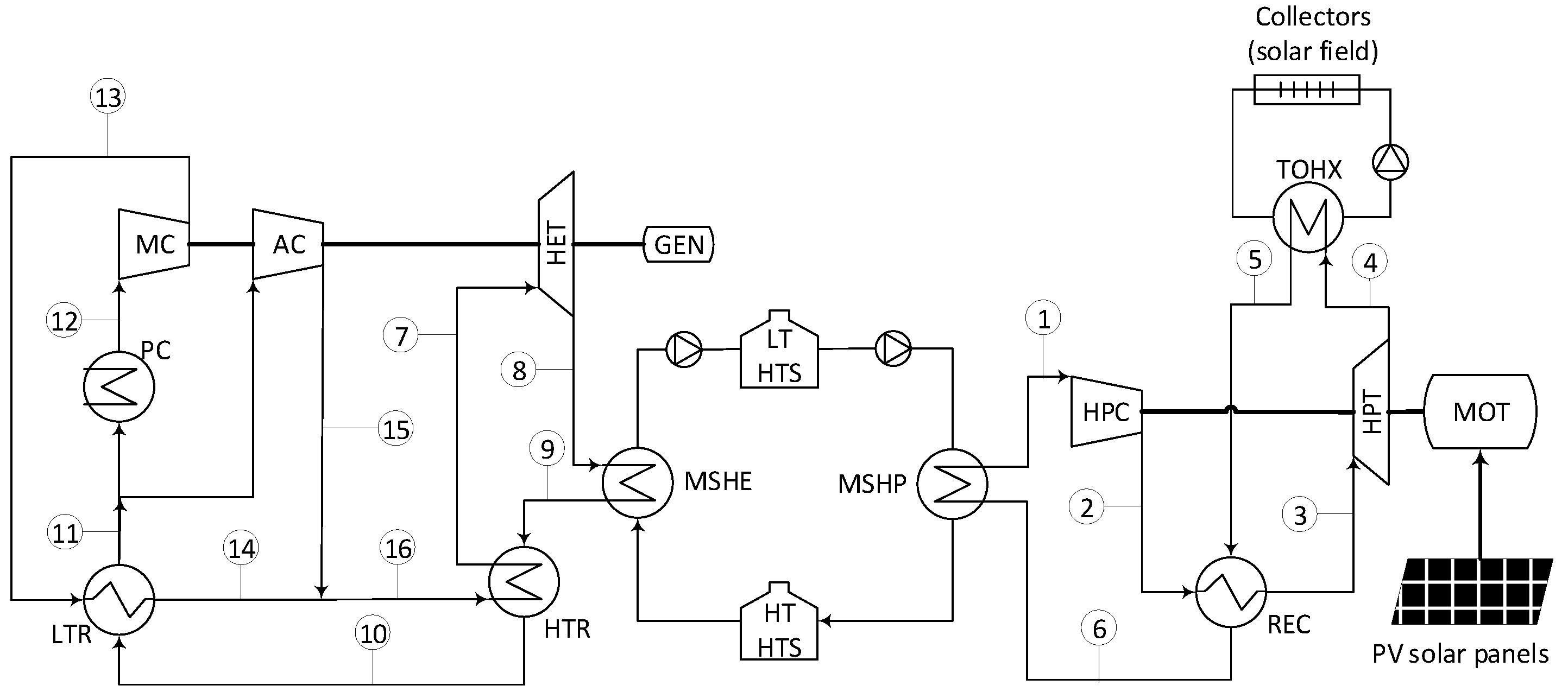
Figure 2 depicts the proposed layout, providing a detailed overview of the heat pump and heat engine components. The heat pump employs a reverse recuperated Brayton cycle, while the heat engine utilizes a recompression Brayton power cycle, both with supercritical CO2. In the two cases, the heat exchangers that employ molten salts (MSHP in the heat pump and MSHE in the heat engine) have been relocated to the low-pressure side of the cycle. This modification is required because both Brayton cycles operate with a maximum pressure of 300 bar. To handle such a high pressure, printed circuit heat exchangers (PCHE) are typically employed in S-CO2 applications [34]. Based on diffusion bonding, PCHEs can withstand high pressures due to their manufacturing process. However, the channels in these heat exchangers are too narrow, leading to clogging issues when using molten salts. The allocation of molten salt heat exchangers in the proposed layouts enables using a heat exchanger with wide channels for the salt, avoiding clogging issues [35]. One possible option for that kind of heat exchanger might be a hybrid printed circuit heat exchanger, where the layers of one of the streams are replaced with a plate-and-fin structure, becoming a combination of a PCHE and a plate-fin heat exchanger (PFHE). A similar heat exchanger configuration has been proposed for sodium fast reactor (SFR) Generation IV nuclear reactors, where liquid metal cools the reactor by circulating through the plate-fin structure while CO2 flows through the semi-circular channels [36]. These heat exchangers are available from Heatric since 2006, and are known as hybrid heat exchangers (H2X). They are manufactured using chemically etched sheets and corrugated fins [37]. In the current application, CO2 would flow through the semi-circular channels, while molten salts would flow through the corrugated fins. The corrugated fins are designed to withstand pressures of 200-220 bar [37], making them suitable for their use on the low-pressure side (85 bar [35]).

2.2. Heat pump

The heat pump receives a low-temperature heat input ranging from 300 °C to 390 °C from the thermal oil of the solar field. It then releases high-temperature heat into the molten salts loop, with temperatures ranging from 405 °C to 589 °C. A reverse recuperated Brayton cycle has been adopted to achieve a sensible heat transfer profile in the working fluid of the heat pump. This cycle operates far from the critical point, leading to a nearly ideal gas behaviour.
The cycle can be described as follows: the low-pressure and temperature stream (4) exiting the turbine (HPT) absorbs heat from the low-temperature reservoir in the thermal oil/CO2 heat exchanger (TOHX). A second stage of heating (5-6) takes place in the recuperator (REC), utilizing the high temperature of the stream leaving the compressor (2-3). Subsequently, the low-pressure stream, now at a high temperature after these two heating stages, provides thermal energy to the hot sink (6-1) via the CO2/molten salt heat exchanger (MSHP). After that, the low-pressure stream enters the compressor (HPC), which increases its pressure and temperature (1-2). After the compressor, the high-pressure stream releases heat in the recuperator (2-3), returning to the turbine inlet conditions (3).
The isentropic efficiencies of the turbine and compressor have been set to 92% and 88%, respectively [38]. The recuperator's temperature approach is assumed to be 5 K, and 10 K in the low-temperature molten salts/CO2 heat exchanger. The compressor’s outlet pressure is 300 bar, with an inlet pressure of 85 bar and a temperature of 415 °C. Pressure drops of 2% have been considered for each stream in the heat exchangers [34].

2.3. Heat engine

A Brayton supercritical CO2 power cycle has been selected for the heat engine [34], recommended by the National Renewable Energy Laboratory of the US for future concentrated solar power plants [39]. This power cycle is chosen mainly for its compactness and efficient operation at moderate temperatures. The high efficiencies achieved by S-CO2 power cycles [34] are due to the proximity of the compressor inlet to the critical point of CO2 (31.1 °C and 73.8 bar), which reduces the work required for compression. However, that proximity can cause density variations, which can be managed by setting the compressor inlet pressure at 85 bar to strike a balance between stable operation and reduced compression energy consumption [35]. Another challenge that may arise in the compressor is the occurrence of phase-change phenomena resulting from local flow accelerations. Operating in the two-phase region can negatively impact compressor performance, causing erosion and degradation of certain components. To carefully design the main compressor while considering these challenges is crucial to prevent such issues and ensure the reliable functioning of the power cycle.
Furthermore, working close to the critical point also poses a problem in a simple recuperated Brayton cycle. The specific heat of CO2 in the low-pressure stream of the recuperator is lower than that in the high-pressure stream, resulting in an imbalanced temperature profile that prevents achieving maximum performance in the heat recovery process. This problem is commonly addressed by dividing the recuperator into two units, leading to the implementation of a re-compression cycle [34].
Based on Figure 2, which illustrates the heat engine employed in this study, the CO2 exiting the turbine (HET) absorbs thermal energy from the molten salts in the molten salts/CO2 heat exchanger (MSHE) (8-9) and transfers it to the cold stream (16-7) in the high-temperature recuperator (HTR), reaching the turbine’s inlet condition. After leaving the HTR, the hot stream once again transfers thermal energy (10-11) in the low-temperature recuperator (LTR) to the cold stream (13-14). Notably, the mass flow rate of the cold stream in the LTR (high-pressure stream) is lower than that of the hot stream (low-pressure). This factor is crucial in recompression cycles to achieve balance in the LTR since the high-pressure stream has a higher specific heat than the low-pressure stream. The division of mass flow rate occurs at the inlet (11) of the precooler (PC). Then, the main flow undergoes cooling (11-12) and compression (12-13) in the main compressor (MC), while the remaining flow (14-15) is directly sent to the auxiliary compressor (AC). As this stream is compressed without previous cooling, it reaches an appropriate temperature to be mixed with the cold stream leaving the LTR (14-15-16), forming the cold stream that enters the HTR.
The turbine’s isentropic efficiency is assumed to be 92%, and an efficiency of 88% is considered for both compressors [38]. A temperature approach of 5 K is employed in the HTR and 5.5 K in the LTR. The approach temperature in the MSHE has been set to 10 K. The outlet pressure of the main compressor is set to 300 bar, with an inlet temperature of 35 °C and an inlet pressure of 85 bar. Pressure drops of 2% are considered for each stream of the heat exchangers [34].

2.4. Solar field

The solar field consists of parabolic trough collectors that use Therminol VP1 [40] as the heat transfer fluid. This choice of fluid is well-established and widely adopted for the specific temperature range under consideration [32].
To determine the solar field's appropriate sizing and nominal performance, the design point has been selected as the 21st of June at solar noon in Seville (Spain). At this point, the direct normal irradiation (DNI) is set to 900 W/m2. The specific type of parabolic trough collector employed is the Eurotrough, detailed in Table 1 [41]. The thermal performance calculation considers the heat losses correlation provided by the manufacturer [42].
Table 1 shows that there are a total number of 78 loops in the system. Each loop comprises 4 collectors, and each collector consists of 10 modules. The overall length of each loop is 490.8 m. Table 2 provides a summary of the key parameters that characterise the nominal performance of each loop.

2.5. Sizing of heat exchangers

In the heat pump and heat engine, two types of heat exchangers have been used: hybrid (H2X) and printed circuit heat exchangers (PCHE). As explained earlier, H2X prevents potential clogging problems, while PCHEs are commonly employed in S-CO2 applications to withstand high-pressure differences.
An iterative design approach has been used to perform the sizing of the heat exchangers, based on the sub-heat exchangers methodology. Sizing calculations are greatly influenced by the significant changes in CO2 properties, particularly when the operating conditions are close to the critical point. This method assumes a continuous variation of properties throughout the sub-heat exchangers that comprise the entire unit [43].
Using the information supplied by the leading manufacturer of the PCHEs [44], the maximum plate size is 600 × 1500 mm. Modules are built with the plates, assuming a core block with a maximum height of 600 mm. This configuration results in a total of 96,000 channels (48,000 per stream). This kind of design comes from the manufacturer [45], and the authors have previously employed it in a CSP project [35]. The channels where the fluid flows are semicircles with a 2 mm diameter and a 2.5 mm pitch. The thickness of the plates is 1.6 mm. Inconel alloy 617 has been recommended for both the receiver (REC) and high-temperature recuperator (HTR) due to the elevated temperatures [46]. Austenitic stainless steel 316L has been selected for the remaining PCHEs.
The overall heat transfer coefficient for each sub-heat exchanger has been evaluated following the methodology described by Dostal [34]. The length of the heat exchanger is determined using the heat transfer across the surface area; consequently, the pressure drop along the entire channel is assessed for every stream. The total number of channels is iterated during the design process until the desired temperatures at each port are achieved. If the calculated maximum pressure drop exceeds or falls below the desired value, the number of tubes increases or decreases accordingly.

2.6. Economic model

The estimated investment cost (fixed capital investment, FCI, based on [47]) has been determined. The total cost can be split into direct and indirect costs, with indirect costs considered to be 25 % of the direct costs. Indirect costs encompass engineering and supervision, construction and contingencies. Direct costs include on-site costs (piping instrumentation and controls, equipment) and off-site expenses (civil works, land and service facilities). For this study, the off-site costs have been incorporated into the solar field and the storage systems, which are directly accounted for in the direct costs. The remaining portion of the facility’s cost is determined based on the purchased equipment cost (PEC) by multiplying it by a factor of 2.18, taken from a study from Sandia National Laboratory [48] for a recompression Brayton supercritical CO2 cycle of 10 MWe [48]. This study has been also used to estimate the cost of the heat engine and heat pump cycles.
The PCHEs’ costs are obtained by scaling them according to the number of modules. An escalation factor of 0.4 [47] is applied, with a base PEC of 5 M$ for the HTR and REC, and a number of modules of 4.46. For the remaining PCHEs, the base PEC is assumed as 3 M$ and a number of modules of 3.1. These cost figures are based on data from 2013 [48]. The cost difference in the PCHEs is due to the different operating conditions in the HTR and REC and the rest of the PCHEs: the HTR and REC operate at high temperatures, necessitating a high-strength alloy such as Inconel 617. In contrast, the other heat exchangers can be manufactured using a standard SS 316 material [49]. The sizing of the H2X heat exchangers has yet to be investigated. Instead, the specific cost ($/kW) obtained for PCHEs within a similar temperature range has been considered to estimate the investment required.
Equations 6 to 9 represent the escalation process required to estimate the investment in turbomachinery, in the generator of the heat engine and the motor in the heat pump, respectively, taken from [50]. In these equations, W stands for the electricity power (produced by the heat engine and consumed by the heat pump) in MW, p for the highest pressure in bar and T for the highest temperature in Celsius degrees. Finally, the PEC of the set is given in million dollars.
f W = W 10 0.68
f p = p 200 0.6
f T = 3.35 + T 1000 7.8 3.35 + 650 1000 7.8
P E C = f W · f p · f T · 6
The thermal energy storage cost has been estimated from the NREL Gen3 roadmap for CSP [39], considering a two-tank solar salt system from Abengoa as a reference. The costs provided include both on-site and off-site expenses, representing direct costs. The volume of the cold tank serves as the baseline (15,700 m3), and an escalation factor of 0.8 is used. The base cost breakdown is: hot tank 10.016 M$, cold tank 4.361 M$, tank insulation 3.724 M$, foundations 3.050 M$, structural steel 0.666 M$, electrical installations 0.481 M$, site works 0.339 M$ and instrumentation 0.212 M$. The cost of the salt inventory varies linearly and is calculated at a specific cost of 1,100 $/tonne. For the solar field investment cost estimation, a specific cost of $152 per solar aperture area has been considered, with reference to 2020 [51].
A time scaling technique is applied using the Chemical Engineering Plant Cost Index (CEPCI) to account for data from different dates. The CEPCI value for 2013 (applicable to molten salts loops, PCHEs, and turbomachines) is 567.3, while the value for 2020 (the year the results are referenced) is 596.2.
A preliminary calculation of the LCOE is performed, considering just the known investment, previously determined. Equation 10 allows to calculate the LCOE, where CRF refers to the capital recovery factor, as defined in equation 11 , W ˙ H E stands for the net power of the heat engine and H H E represents the equivalent operating hours of the heat engine per day at constant load. In equation 11, the variable wacc denotes the weighted average capital cost, assumed to be 7.5%, and N represents the project’s lifespan, in this case set at 25 years. Concerning the investment in the PV field, an LCOE of 25 €/MWh [30] is used, with a production of 1,800 equivalent hours per year.
L C O E = F C I · C R F W ˙ H E · H H E · 365
C R F = w a c c · 1 + w a c c N 1 + w a c c N 1

3. Results

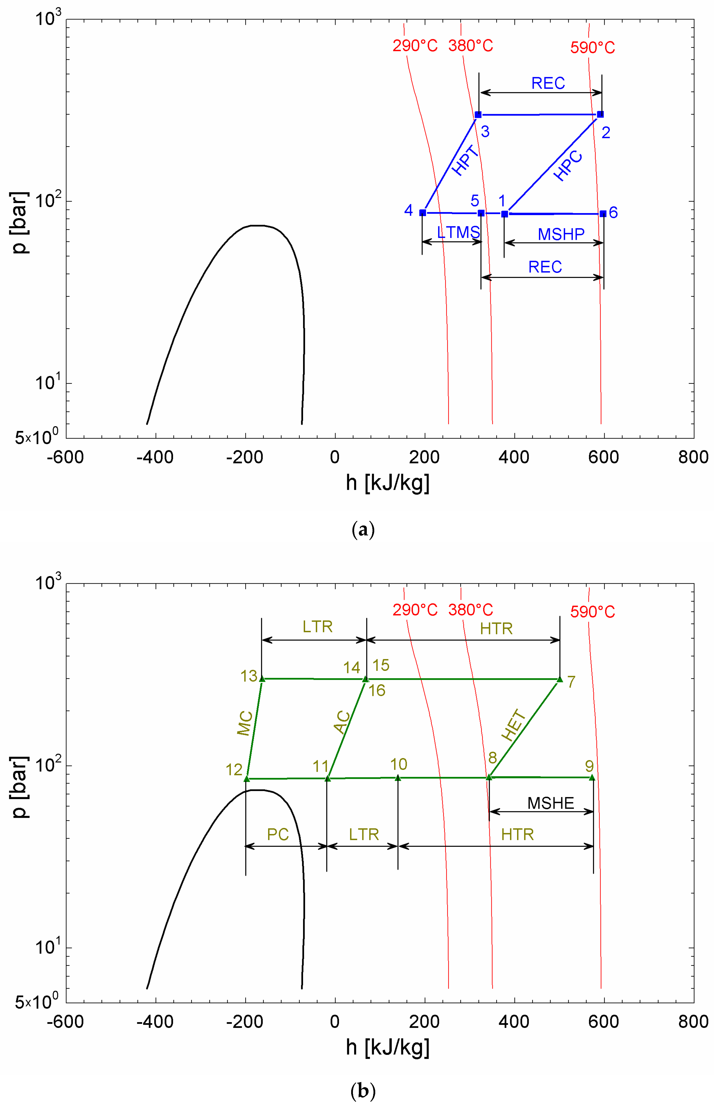
Table 3 and Table 4 present the characteristics of the state points for the heat pump and heat engine, respectively. Figure 3 illustrates the p-h diagram for both thermodynamic cycles, with Figure 3a representing the heat pump and Figure 3b the heat engine. It is important to note that the compression processes in the heat engine display steeper slopes, especially in the main compressor, as they operate in the proximity to the critical point. On the other hand, the behaviour of fluid in the heat pump can be approximated to that of an ideal gas operating in a reverse Brayton cycle. In Figure 3b, the enthalpy change in the LTR exhibits a longer length for the high-pressure stream than for the lower-pressure stream. This discrepancy arises from the lower mass flow ratio in the former, which compensates for its higher specific heat.
Equations 12 and 13 provide the expression for the efficiency ( η H E ) of the heat engine and the COP of the heat pump, respectively. The subscripts in these equations correspond to the same acronyms used for the cycle components. The ratio between the mass flow rate of the main compressor and the turbine of the heat engine is determined to be 0.6772, derived from the LTR balance (same terminal temperature difference at both extremes). It is important to note that the product of the heat engine efficiency and the coefficient of performance (equation 14) represents the ratio of energy production to the energy input from the PV field. This value is slightly greater than 1. This result allows considering the proposed plant as a PV field with storage with certain gain [52].
η H E = W G E N Q M S H E = h 7 h 8 m ˙ M C m ˙ H E T · h 13 h 12 m ˙ A C m ˙ H E T · h 15 h 11 h 9 h 8 = 44.4 %
C O P = Q M S H P W M O T = h 6 h 1 h 2 h 1 h 3 h 4 = 2.32
η H E · C O P = W G E N W M O T = 1.03
The energy balance of the plant is presented in Table 5 and Table 6. The sizing of the solar field, with a capacity of 128 MWth, is based on the dimensions of existing CSP plants in Spain that utilize parabolic trough collectors without storage [32]. As a reference, these plants produce 50 MWe. To ensure the ability to evacuate a portion of the power during production while storing the remainder for later use, the MSHE heat exchanger has been designed to be half the size of the MSHP. Thus, half of the thermal energy discharged by the heat pump is stored in the molten salt tanks. However, for the sake of flexibility, the storage capacity of the tanks has been doubled, being able to store all the heat discharged by the heat pump. This configuration enables the plant to prevent the risk of curtailments.
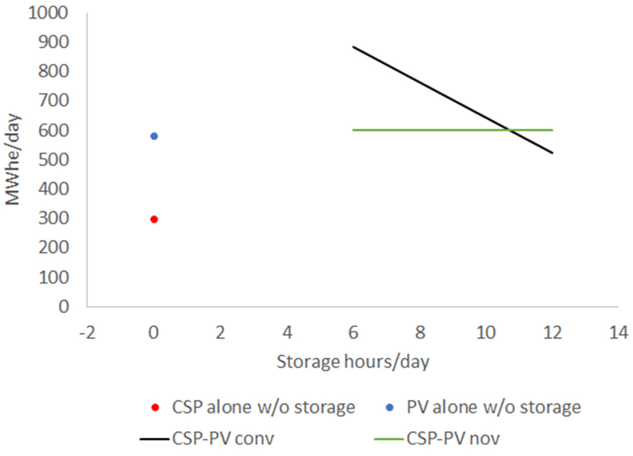
Figure 4 illustrates the performance comparison between the proposed plant and a conventional hybrid CSP-PV plant. To simplify the analysis, a solar radiation period of 6 equivalent hours has been assumed, while storage period ranges from 6 to 12 hours. Additionally, the figure includes a reference to CSP and PV systems without storage, but with the same power capacity. Figure 4 also highlights the capacity loss in conventional hybrid plants due to the use of the Joule effect to increase PV storage.
Table 7, Table 8, Table 9 and Table 10 present the cost breakdown of different components of the proposed plant. By aggregating all the on-site and direct costs and accounting for 25% of indirect costs, a total fixed capital investment of 416.5 M$ is obtained (equivalent to 8,329 $/kWe). Considering a daily production of 600 MWh, the resulting LCOE amounts to 171 $/MWhe.

4. Discussion and Conclusions

The integration of a PV plant and a CSP through a high-temperature heat pump has been analysed. This configuration introduces a novel approach by employing a heat pump as the integration mechanism instead of conventional electrical resistors found in existing CSP-PV plants.
For the proposed system, a recompression Brayton supercritical CO2 cycle is used as the heat engine, whereas a reverse recuperative Brayton cycle, also operating with supercritical CO2, is employed for the heat pump. The thermal energy storage system incorporates a two-tank configuration utilizing solar salt as the medium for storing sensible heat. The solar field consists of parabolic trough collectors, which serve as the cold source for the heat pump. It is important to highlight that the PV plant exclusively drives the heat pump, with no direct injection of PV power into the grid.
The heat pump allows for storing high-grade thermal energy in the molten salts using a parabolic trough collectors field, as if it was produced in an heliostat solar field. Moreover, the integration through the heat pump reduces exergy losses in the storage system. According to Equation 3, and considering the average entropic temperatures [33] of the PTC field (616.9 K) and the molten salts (766.3 K), the exergy loss reduction (calculated in Equation 15) for the storage system amounts to 45.24%.
I c o n v   I n o v I c o n v = C O P C O P m a x = 2.32 5.13 = 45.24 %
The high-temperature heat pump operates within the nearly ideal gas region as depicted in Figure 3a. This characteristic significantly reduces the technological risk associated with the reverse recuperated Brayton cycle. On the other hand, the heat engine, which utilizes the recompression Brayton supercritical CO2 cycle, has limited commercial experience. In early demonstration plants, it could be replaced by a conventional Rankine cycle although losing efficiency. The proposed S-CO2 cycle achieves an efficiency of 44.4%, surpassing the less than 40% observed in current CSP plants [32]).
One notable advantage of this innovative system is its ability to store the entire PV production, ensuring a consistent energy output for a full day, as shown in Figure 4. This becomes an advantage over conventional hybrid plants, where fully storing PV production through electrical resistors in the molten salts reduces the dairy energy production. This becomes particularly advantageous during curtailment scenarios, characterised by a high PV share in the electricity mix and low demand during solar radiation hours.
In terms of costs, the proposed system achieves a LCOE of 171 $/MWh, which is lower than the LCOE of 182 $/MWh for the current CSP with a 45% of capacity factor [53]. Similarly, in [35], a CSP system based on a central tower receiver with a recompression Brayton supercritical CO2 power cycle obtained an LCOE of 238 $/MWh. This demonstrates the significant cost advantage of the heat pump system, as it replaces the expensive heliostat solar field with a combination of a PV plant and a parabolic trough collectors field.
If we consider the same energy production of 600 MWh per day, but with a PV plant of 100 MW capacity and 6 hours of battery storage, the LCOE would be lower than 140 $/MWh (assuming 250 $/kWh [54] for batteries and the total reposition of the batteries along the lifespan of the project). However, it's important to note that this battery system presents two main drawbacks. Firstly, it requires a large amount of critical raw materials. Secondly, it results in the loss of rotational inertia, necessitating additional controls for grid frequency. In contrast, the proposed system injects electricity into the grid through a synchronous generator in the heat engine, and it does not rely on critical raw materials for the storage components.
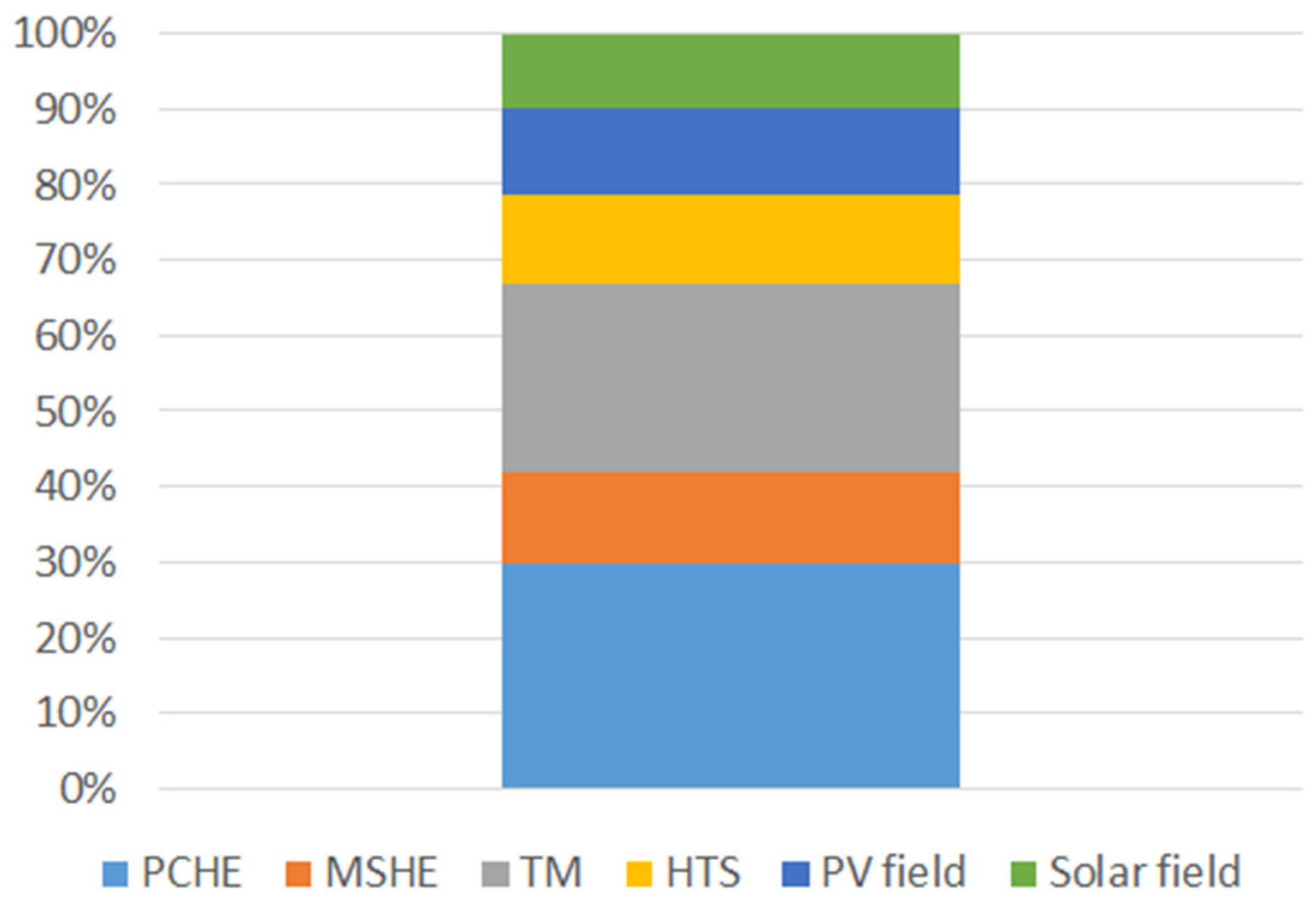
Figure 5 provides a detailed breakdown of the costs associated with this novel system. It reveals that more than half of the total cost is attributed to the PCHE and turbomachines. This fact suggests that there is potential for cost reduction, particularly in these components. Notably, a cost reduction is expected as the S-CO2 technology deploys, because these components, specially the heat engine compressors, are currently in the first steps of the learning curve.
Although the proposed system has not been able to beat the cost of a PV with battery storage, it exhibits several operational and construction advantages. In conclusion, this proposed system effectively reduces the LCOE compared to both current CSP power plants. Additionally, it enhances the performance of current hybrid CSP-PV power plants, especially in terms of long-duration energy storage capabilities.

Author Contributions

Conceptualization, José Linares, Arturo Martín-Colino and Eva Arenas Pinilla; Formal analysis, Eva Arenas Pinilla and María Montes; Funding acquisition, Eva Arenas Pinilla; Investigation, José Linares and Alexis Cantizano; Methodology, Eva Arenas Pinilla, María Montes and Alexis Cantizano; Project administration, José Linares and Eva Arenas Pinilla; Resources, Eva Arenas Pinilla; Software, Alexis Cantizano; Supervision, José Linares; Validation, José Linares, Alexis Cantizano and José Pérez-Domínguez; Visualization, José Pérez-Domínguez; Writing – original draft, José Linares and Arturo Martín-Colino; Writing – review & editing, Eva Arenas Pinilla, Alexis Cantizano and José Pérez-Domínguez.

Funding

This research was funded by Rafael Mariño, Chair on New Energy Technologies of Comillas Pontifical University.

Data Availability Statement

Data sharing not applicable.

Conflicts of Interest

The authors declare no conflict of interest. The funders had no role in the design of the study; in the writing of the manuscript; or in the decision to publish the results.

References

  1. IRENA (2023), Renewable capacity statistics 2023, International Renewable Energy Agency, Abu Dhabi.
  2. Powell K.M., Rashid, Ellingwood K., Tuttle J., Iverson B.D., Hybrid concentrated solar thermal power systems: A review, Renewable and Sustainable Energy Reviews 80 (2017) 215-237. [CrossRef]
  3. Ju X., Xu C., Hu Y., Han X., Wei G., Du X., A review on the development of photovoltaic/concentrated solar power (PV-CSP) hybrid systems, Solar Energy Materials and Solar Cells 161 (2017) 305-327. [CrossRef]
  4. Pilotti, L.; Colombari, M.; Castelli, A.; Binotti, M.; Giaconia, A.; Martelli, E. Simultaneous design and operational optimization of hybrid CSP-PV plants. Appl. Energy 2023, 331. [CrossRef]
  5. Okonkwo, E.C.; Wole-Osho, I.; Bamisile, O.; Abid, M.; Al-Ansari, T. Grid integration of renewable energy in Qatar: Potentials and limitations. Energy 2021, 235, 121310. [CrossRef]
  6. Starke, A.R.; Cardemil, J.M.; Escobar, R.A.; Colle, S. Assessing the performance of hybrid CSP+PV plants in northern Chile. Sol. Energy 2016, 138, 88–97. [CrossRef]
  7. Pan C.A., Dinter F., Combination of PV and central receiver CSP plants for base load power generation in South Africa, Solar Energy 146 (2017) 379-388. [CrossRef]
  8. Green A., Diep C., Dunn R., Dent J., High Capacity Factor CSP-PV Hybrid Systems, Energy Procedia 69(2015) 2049-2059. [CrossRef]
  9. Starke, A.R.; Cardemil, J.M.; Escobar, R.; Colle, S. Multi-objective optimization of hybrid CSP+PV system using genetic algorithm. Energy 2018, 147, 490–503. [CrossRef]
  10. Parrado, C.; Girard, A.; Simon, F.; Fuentealba, E. 2050 LCOE (Levelized Cost of Energy) projection for a hybrid PV (photovoltaic)-CSP (concentrated solar power) plant in the Atacama Desert, Chile. Energy 2016, 94, 422–430. [CrossRef]
  11. Sumayli, H.; El-Leathy, A.; Danish, S.N.; Al-Ansary, H.; Almutairi, Z.; Al-Suhaibani, Z.; Saleh, N.S.; Saeed, R.S.; Alswaiyd, A.; Djajadiwinata, E.; et al. Integrated CSP-PV hybrid solar power plant for two cities in Saudi Arabia. Case Stud. Therm. Eng. 2023, 44. [CrossRef]
  12. Stein W.H., Buck R., Advanced power cycles for concentrated solar power, Solar Energy 152 (2017) 91-105. [CrossRef]
  13. Guccione, S.; Trevisan, S.; Guedez, R.; Laumert, B.; Maccarini, S.; Traverso, A. Techno-Economic Optimization of a Hybrid PV-CSP Plant With Molten Salt Thermal Energy Storage and Supercritical CO2 Brayton Power Cycle. Proceedings of the ASME Turbo Expo 2022, Volume 4; Cycle Innovations: Energy Storage. 2022. [CrossRef]
  14. Yang J., Yang Z., Duan Y., Novel design optimization of concentrated solar power plant with S-CO2 Brayton cycle based on annual off-design performance, Applied Thermal Engineering 192 (2021) 116924. [CrossRef]
  15. Yang J., Yang Z., Duan Y., Load matching and techno-economic analysis of CSP plant with S–CO2 Brayton cycle in CSP-PV-wind hybrid system, Energy 223 (2021) 120016. [CrossRef]
  16. Zurita, A.; Mata-Torres, C.; Valenzuela, C.; Felbol, C.; Cardemil, J.M.; Guzmán, A.M.; Escobar, R.A. Techno-economic evaluation of a hybrid CSP + PV plant integrated with thermal energy storage and a large-scale battery energy storage system for base generation. Sol. Energy 2018, 173, 1262–1277. [CrossRef]
  17. Liu T., Yang J., Yang Z., Duan Y., Techno-economic feasibility of solar power plants considering PV/CSP with electrical/thermal energy storage system, Energy Conversion and Management 255 (2022) 115308. [CrossRef]
  18. Cox, J.L.; Hamilton, W.T.; Newman, A.M. Parametric analysis on optimized design of hybrid solar power plants. Sol. Energy 2023, 252, 195–217. [CrossRef]
  19. Bravo, R.; Friedrich, D. Integration of energy storage with hybrid solar power plants. Energy Procedia 2018, 151, 182–186. [CrossRef]
  20. Zurita, A.; Mata-Torres, C.; Cardemil, J.M.; Guédez, R.; Escobar, R.A. Multi-objective optimal design of solar power plants with storage systems according to dispatch strategy. Energy 2021, 237, 121627. [CrossRef]
  21. Giaconia, A.; Grena, R. A model of integration between PV and thermal CSP technologies. Sol. Energy 2021, 224, 149–159. [CrossRef]
  22. Bravo, R.; Friedrich, D. Two-stage optimisation of hybrid solar power plants. Sol. Energy 2018, 164, 187–199. [CrossRef]
  23. Kong L., Chen X., Gong J., Fan D., Wang B., Li S., Optimization of the hybrid solar power plants comprising photovoltaic and concentrating solar power using the butterfly algorithm, Energy Conversion and Management 257 (2022) 1153. [CrossRef]
  24. Richter, P.; Trimborn, T.; Aldenhoff, L. Predictive storage strategy for optimal design of hybrid CSP-PV plants with immersion heater. Sol. Energy 2021, 218, 237–250. [CrossRef]
  25. Chennaif, M.; Zahboune, H.; Elhafyani, M.; Zouggar, S. Electric System Cascade Extended Analysis for optimal sizing of an autonomous hybrid CSP/PV/wind system with Battery Energy Storage System and thermal energy storage. Energy 2021, 227, 120444. [CrossRef]
  26. Zurita, A.; Mata-Torres, C.; Cardemil, J.M.; Escobar, R.A. Assessment of time resolution impact on the modeling of a hybrid CSP-PV plant: A case of study in Chile. Sol. Energy 2020, 202, 553–570. [CrossRef]
  27. Aguilar-Jiménez, J.; Velázquez, N.; Acuña, A.; Cota, R.; González, E.; González, L.; López, R.; Islas, S. Techno-economic analysis of a hybrid PV-CSP system with thermal energy storage applied to isolated microgrids. Sol. Energy 2018, 174, 55–65. [CrossRef]
  28. Valenzuela, C.; Mata-Torres, C.; Cardemil, J.M.; Escobar, R.A. CSP + PV hybrid solar plants for power and water cogeneration in northern Chile. Sol. Energy 2017, 157, 713–726. [CrossRef]
  29. https://www.solarsco2ol.eu/.
  30. 30. IEA & NEA, Projected costs of generating electricity, 2020 Edition. Available at: https://www.iea.org/reports/projected-costs-of-generating-electricity-2020 (visited on June 6, 2023).
  31. LAZARD, LCOE+, April 2023. Available at: https://www.lazard.com/research-insights/2023-levelized-cost-of-energyplus/ (visited on June 6, 2023).
  32. https://www.solarpaces-conference.org/.
  33. Bejan, A. Advanced Engineering Thermodynamics, 3rd ed.; John Wiley & Sons Inc.: Hoboken, NJ, USA, 2006.
  34. Dostal V., A Supercritical Carbon Dioxide Cycle for Next Generation Nuclear Reactors, Institute of Technology, Massachusetts, 2004 Feb. Doctoral Thesis.
  35. Linares, J.I.; Montes, M.J.; Cantizano, A.; Sánchez, C. A novel supercritical CO2 recompression Brayton power cycle for power tower concentrating solar plants. Appl. Energy 2020, 263, 114644. [CrossRef]
  36. Saranam, V.R.; Paul, B.K. Feasibility of Using Diffusion Bonding for Producing Hybrid Printed Circuit Heat Exchangers for Nuclear Energy Applications. Procedia Manuf. 2018, 26, 560–569. [CrossRef]
  37. Southall D., Dewson S.J., Innovative compact heat exchangers, Proceedings of ICAPP ’10, San Diego, CA, USA, June 13-17, 2010. Paper 10300.
  38. Bahamonde-Noriega J.S., Design Method for S-CO2 Gas Turbine Power Plants, Delft University of Technology, The Netherlands, 2012 (MSc Dissertation).
  39. Mehos, M.; Turchi, C.; Vidal, J.; Wagner, M.; Ma, Z.; Ho, C.; Kolb, W.; Andraka, C.; Kruizenga, A. Concentrating Solar Power Gen3 Demonstration Roadmap. In Concentrating Solar Power Gen3 Demonstration Roadmap; Office of Scientific and Technical Information (OSTI): Golden, CO, USA, 2017; pp. 1–140.
  40. Therminol, 2023: https://www.therminol.com/heat-transfer-fluids.
  41. Montes, M.J.; Abánades, A.; Martínez-Val, J.M.; Valdés, M. Solar multiple optimization for a solar-only thermal power plant, using oil as heat transfer fluid in the parabolic trough collectors. Sol. Energy 2009, 83, 2165–2176. [CrossRef]
  42. EuroTrough Project. Final Public Report, European Commission Contract No. JOR3-CT98-00231, Sevilla/Almería/Brussels, 2001.
  43. Serrano, I.; Cantizano, A.; Linares, J.; Moratilla, B. Modeling and sizing of the heat exchangers of a new supercritical CO2 Brayton power cycle for energy conversion for fusion reactors. Fusion Eng. Des. 2014, 89, 1905–1908. [CrossRef]
  44. https://www.heatric.com/.
  45. Pierres R.L., Southall D., Osborne S., Impact of Mechanical Design Issues on Printed Circuit Heat Exchangers, Proceedings of 3rd SCO2 Power Cycle Symposium, Colorado, USA.
  46. Li X., Smith T., Kininmont D., Dewson S. (2009). Materials for Nuclear Diffusion-Bonded Compact Heat Exchangers, Proceedings of ICAPP'09, Tokyo, Japan, May 10-14, 2009.
  47. Bejan A., Tsatsaronis G., Moran M., Thermal Design & Optimization, Wiley, 1996.
  48. Fleming D.D. et al., Scaling Considerations for a Multi-Megawatt Class Supercritical CO2 Brayton Cycle and Commercialization, SANDIA REPORT SAND2013-9106 (2013).
  49. Southall D., Pierres R.L., Dewson S.J., Design considerations for compact heat exchangers, Proceedings of ICAPP ’08, California, USA, June 2008.
  50. Driscoll M.J., Hejzlar P., 300 MWe Supercritical CO2 Plant Layout and Design, MIT Nuclear Engineering Department (2004), MIT-GFR-014.
  51. Kurup, P.; Glynn, S.; Akar, S. Manufacturing cost analysis of advanced parabolic trough collector. AIP Conference Proceedings 2022, 2445, 02006. [CrossRef]
  52. Linares, J.I.; Martín-Colino, A.; Arenas, E.; Montes, M.J.; Cantizano, A.; Pérez-Domínguez, J.R. Carnot Battery Based on Brayton Supercritical CO2 Thermal Machines Using Concentrated Solar Thermal Energy as a Low-Temperature Source. Energies 2023, 16, 3871. [CrossRef]
  53. IRENA. Renewable Power Generation Costs in 2017; IRENA: Abu Dhabi, United Arab Emirates, 2018; ISBN 978-92-9260-040-2.
  54. Tafur-Escanta, P.; Valencia-Chapi, R.; López-Guillem, M.; Fierros-Peraza, O.; Muñoz-Antón, J. Electrical energy storage using a supercritical CO2 heat pump. Energy Rep. 2022, 8, 502–507. [CrossRef]
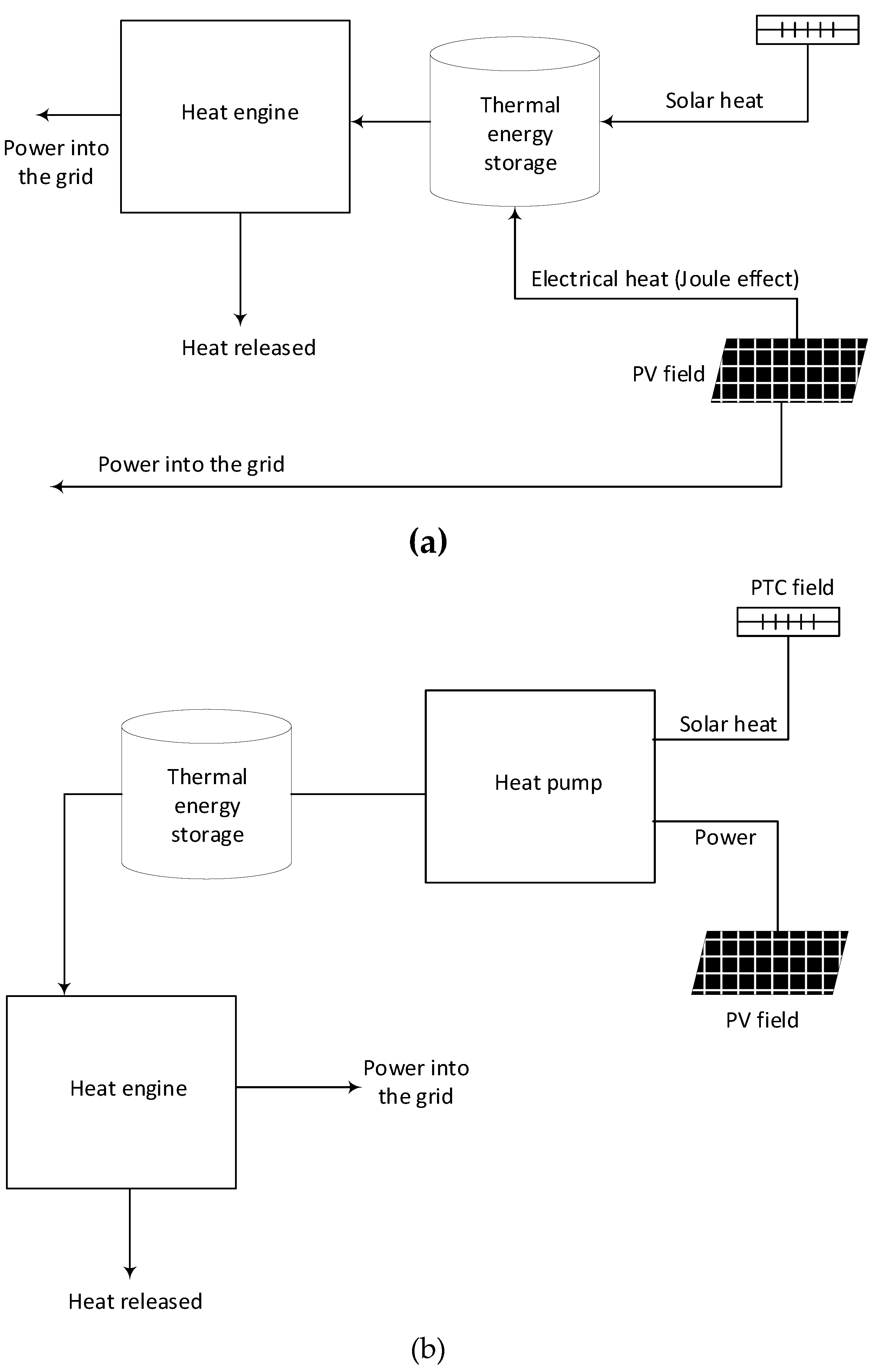
Figure 1. Conceptual types of hybrid CSP-PV plants: (a) Conventional; (b) Novel scheme proposed in this work.
Preprints 77872 g001
Figure 2. Proposed layout.
Preprints 77872 g002
Figure 3. Pressure-enthalpy diagrams: (a) Heat pump; (b) Heat engine.
Preprints 77872 g003
Figure 4. Performance comparison between novel hybrid plant (nov) and conventional (conv) according to storage capacity. An equivalent solar radiation period of 6 hours is assumed.
Preprints 77872 g004
Figure 5. Cost breakdown of the novel hybrid CSP-PV plant.
Preprints 77872 g005
Table 1. Geometric and optical parameters of the solar field [41].
Number of loops in the solar field 78
Number of collectors per loop 4
Number of modules per collector 10
Length of every module [m] 12.27
Absorber tube outer diameter [m] 0.07
Absorber tube inner diameter [m] 0.065
Glass envelope outer diameter [m] 0.115
Glass envelope inner diameter [m] 0.109
Intercept factor 0.92
Mirror reflectivity 0.92
Glass transmissivity 0.945
Solar absorptivity 0.94
Peak optical efficiency 0.75
Table 2. Nominal performance of the parabolic trough loop
Mass Flow per loop [kg/s] 7.6
Inlet/Outlet HTF temperature [°C] 300/390
Inlet Pressure [bar] 20
Heat gain per loop [MWth] 1.6732
Heat loss per loop [kWth] 158.56
Pressure drop per loop [bar] 4.1438
Optical efficiency [%] 71.99
Thermal efficiency [%] 91.34
Table 3. Properties at state points (Figure 2) of the heat pump.
Point Pressure [bar] Temperature [°C] Enthalpy [kJ/kg]
1 85.00 415.0 377.3
2 300.0 604.1 590.8
3 294.0 388.5 318.3
4 90.31 261.4 199.6
5 88.5 370.0 324.5
6 86.73 599.1 596.9
Table 4. Properties at state points (Figure 2) of the heat engine.
Point Pressure [bar] Temperature [°C] Enthalpy [kJ/kg]
7 288.1 532.8 501.0
8 92.15 395.8 353.8
9 90.31 579.1 572.3
10 88.50 203.6 133.9
11 86.73 82.02 -18.61
12 85.00 35.00 -197.9
13 300.0 76.52 -163.3
14 294.0 198.1 61.88
15 294.0 199.6 64.25
16 294.0 198.6 62.65
Table 5. Energy balance at the design point of the heat pump (Figure 2). In the heat exchangers, the hot stream is designed in the first place.
Component Heat duty or Power
[MW]
Mass flow rate
[kg/s]
Compressor (HPC) 219 1025
Turbine (HPT) 122 1025
Motor (MOT) 97 ---
CO2/CO2 (REC) 279 1025/1025
Thermal Oil/CO2 (TOHX) 128 582/1025
CO2/Molten salts (MSHP) 225 1025/798
Table 6. Energy balance at the design point of the heat engine (Figure 2). In the heat exchangers, the hot stream is designed in the first place.
Component Heat duty or Power
[MW]
Mass flow rate
[kg/s]
Main Compressor (MC) 12 349
Auxiliary Compressor (AC) 14 167
Turbine (HET) 76 516
Generator (GEN) 50 ---
CO2/CO2 (HTR) 226 516/516
CO2/CO2 (LTR) 779 516/349
Molten salts/CO2 (MSHE) 113 399/516
CO2/Water (PC) 63 349/2995
Table 7. Size and costs of PCHE
Component Heat duty
[MW]
Height
[m]
Number of
modules
On-site
Cost [M$2020]
REC 279 3.92 96 37.1
HTR 226 2.67 22 20.6
LTR 79 4.25 32 16.6
PC 63 0.43 11 10.8
TOHX 128 0.40 8 9.7
Table 8. Costs of H2X.
Component Heat duty
[MW]
Reference
PCHE
On-site
Cost per unit
[M$2020]
MSHP 225 REC 28.6
MSHE 113 HTR 9.8
Table 9. Turbomachines and electrical machines costs.
Cycle On-site
Cost [M$2020]
HP 47.9
HE 31.1
Table 10. Molten salt loops, PTC and PV costs.
Component Energy stored
[MWh]
Salt inventory
[ton]
Direct Costs [M$2020]
TES 1,351 17,245 38.6
PV field --- --- 38.9
PTC Field --- --- 32.5
Disclaimer/Publisher’s Note: The statements, opinions and data contained in all publications are solely those of the individual author(s) and contributor(s) and not of MDPI and/or the editor(s). MDPI and/or the editor(s) disclaim responsibility for any injury to people or property resulting from any ideas, methods, instructions or products referred to in the content.
Copyright: This open access article is published under a Creative Commons CC BY 4.0 license, which permit the free download, distribution, and reuse, provided that the author and preprint are cited in any reuse.
Prerpints.org logo

Preprints.org is a free preprint server supported by MDPI in Basel, Switzerland.

Subscribe

© 2024 MDPI (Basel, Switzerland) unless otherwise stated