1. Introduction
Active Phased Array Technology enables radars to have high performance and high survivability while reducing the cost of radar development, so active phased array radar antennas are widely used in satellite imaging, aircraft early warning, battlefield reconnaissance, ground air defense, and other fields [
1]. Active phased array antennas are composed of many active components and electronic devices. Because of the miniaturization of microelectronics technology, the development trend of high integration, making microelectronics devices work when the heat flux per unit area within the device increased significantly, which is currently the main reason for the performance of the electronic devices to decline appreciation failure. According to statistics, the reliability of the system will decrease by 50% when the temperature of electronic devices increases by 10℃. The cooling system can reduce electronic device temperature and maintain electrical performance stability, which has become an indispensable part of electronic device design [
2,
3,
4]. The proposal and research of embedded cooling, i.e., direct cooling, has shifted the direction of chip cooling from traditional remote cooling to proximity cooling, i.e., the cooling mass is delivered directly into the chip substrate or adapter plate for cooling. This approach to heat dissipation ignores the numerous interface materials and component housings that impede heat dissipation, thus minimizing the total thermal resistance between the chip junction and the terminal thermal sink and achieving efficient heat dissipation [
7]. This new approach to thermal control opens more possibilities for today's thermal dilemmas.
Embedded cooling is described in the literature [
8] as a third-generation thermal management technology for electronic circuits and is a research focus in DARPA's Near-Junction Thermal Transport (NJTT) and Intra/Inter-Chip Enhanced Cooling Thermal Packaging (ICECool) programs. li Zheng [
9] et al. proposed a novel stacked embedded microfluidic cooling system for chip I/O interconnects, enabling high broadband signals, embedded microfluidic cooling, and power transfer for high-performance stacked ICs. An embedded cooling system was demonstrated by John Ditr [
10] and others. The coolant crosses the interposer material directly into the interior of the chip package, closer to the actual heat-generating transistors in the chip than a cold-plate-based cooling solution. This cooling solution reduces the total thermal resistance by a factor of three or more compared to the total thermal resistance of conventional remote cooling methods due to the many reduced thermal interfaces. The thermal performance of the designed embedded cooling system is also experimentally verified.
Remco van Erp [
11,
12] proposed a new thermal management method for liquid-cooled GaN-based power integrated circuits embedded directly in Si substrates, with PCBs as the delivery platform. The coefficient of performance of a manifold thermal structure etched into the Si substrate is increased by a factor of 50 over that of a straight microchannel. This co-design of microfluidic channels and electronics in semiconductor substrates can further improve integration. In the literature [
13], microchannel heat sinks were integrated into Si substrates for GaN-based power integrated circuits. This solution reduces the thermal resistance by a factor of 25 compared to forced air cooling. Experimental measurements show that integrated liquid cooling reduces the impact of self-heating on electrical performance. Research teams such as Lockheed Martin and Purdue University have conducted studies and experiments related to embedded cooling, and the results show that the direct cooling of the fluid embedded in the chip has a higher thermal efficiency than the traditional convective heat transfer method based on liquid-cooled cold plates. As the latest and most advanced cooling method, many countries have studied and transitioned to embedded cooling, and the experimental data they have completed has confirmed the superior cooling capability of embedded cooling. In China, however, there is still a certain technical shortcoming in microelectronics technology for the time being, and there is very little research work and related reported literature on embedded cooling. Siyuan Miao [
14] introduced the latest and most advanced cooling method-embedded cooling for high-power phased-array antenna chips and conducted a simulation analysis. Chaotin Li [
7] designed two associated cooling schemes for a single chip, the swept-back breakpoint microchannel and the truncated microchannel, with the truncated microchannel cooling scheme being an enhancement of the swept-back breakpoint microchannel cooling scheme. The optimized truncated microchannel shows a 0.81% reduction in maximum temperature and an 8.4% increase in temperature uniformity compared to the through microchannel cooling structure. This indicates that increasing the width of the spoiler fins is beneficial in enhancing thermal performance. The truncated microchannel structure is a flat microchannel in the first half and a breakpoint+fin flow channel in the second half. According to the results, it can be seen that this flow channel can effectively enhance the thermal performance, but at the same time the maximum pressure drop increases significantly and the heat mostly collects in the chip wafer in the middle and lower part of the flow channel, and since the breakpoint+fin flow channel is distributed horizontally and perpendicular to the flow direction of the coolant flowing through the flat channel, the breakpoint+ There are many areas in the runner of the fins where effective contact is not possible.
Therefore, this paper proposes a novel swept-back fishnet-embedded microchannel topology (SBFEMCT), which differs from the truncated microchannel in that the rectangular break point and fins are changed into a diamond lattice to increase the effective contact area and to a certain extent strengthen the disturbance structure in the middle of the microchannel to disturb the fluid boundary layer and weaken the disturbance structure on both sides of the flow channel, which further improves the heat transfer performance and effectively lowers the maximum pressure drop is effectively reduced. In this paper, the latest embedded heat dissipation is investigated from the dimension of a single chip to provide new ideas and references for the next generation of high-performance phased-array antenna heat dissipation technology bottlenecks.
2. Design Methods/Models
2.1. Design Ideas
This is because the highest temperature of the chip wafer when the chip is operating is on the central axis, and the high-temperature range in the center is larger than on the sides, while the temperature on the sides of the chip wafer is slightly lower s[
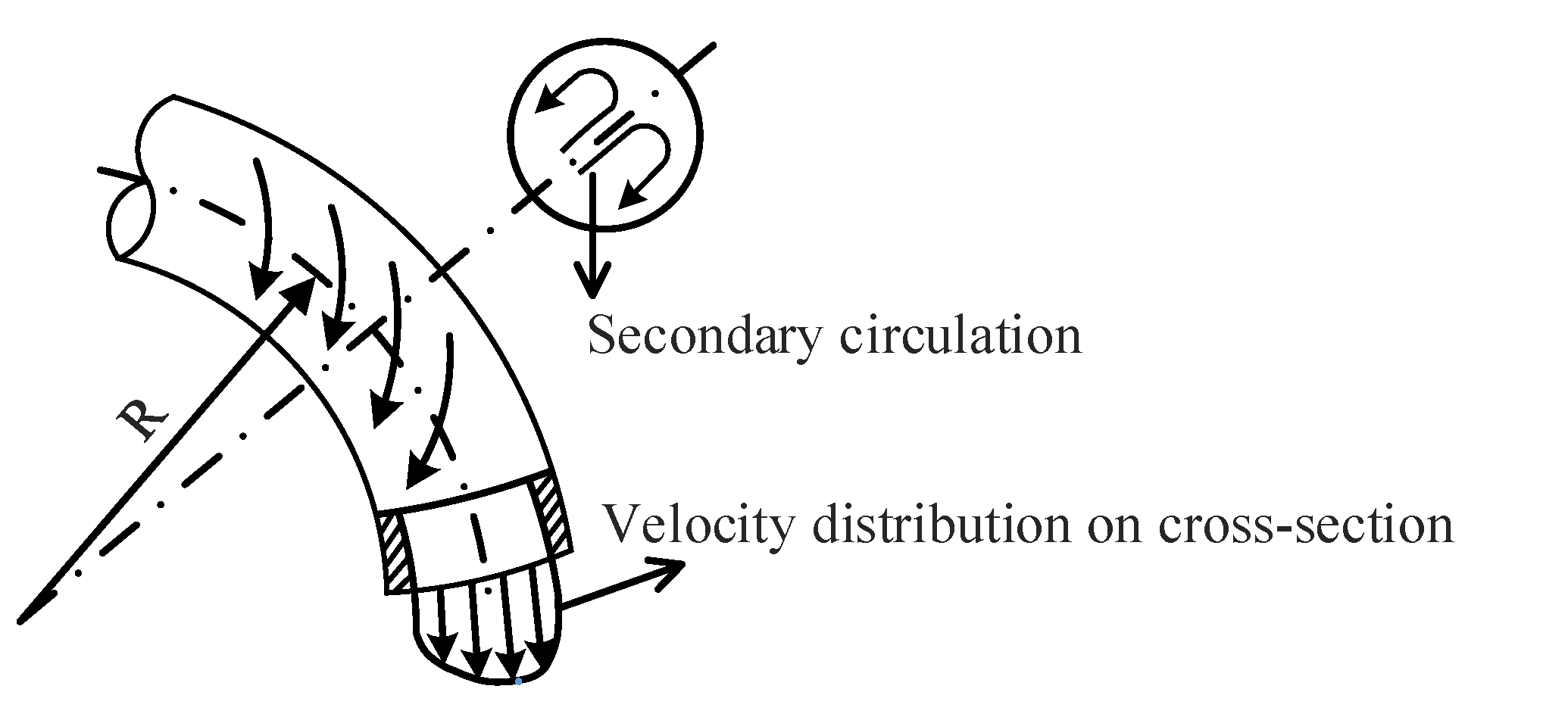
7]. Therefore, to better dissipate heat through the liquid coolant in the embedded flow channel, it can be heavily weighted to bring out the heat generated in the mid-axis, the central part of the chip during operation. To achieve heat dissipation enhancement, structures are often designed to block or direct the fluid to change its original flow direction when designing heat dissipation structures. For example, heat exchangers in everyday life are designed as bent or spiral tubes as shown in
Figure 1. Such structures allow the fluid to be influenced by centrifugal forces during the flow process, thus creating a secondary circulation. The secondary circulation arc makes the fluid in the flow channel participate in heat transfer as much and as fully as possible, thus achieving the purpose of enhancing the heat transfer capacity of the radiator.
Therefore, it can be obtained that if the flow channel structure can make the fluid in the process of flow produce convergence and swirl, it can increase the effective contact area of the fluid and the micro-runner, affect or break the original micro-channel heat exchange layer to improve the heat dissipation performance of the micro-runner heat sink. For example, adding a pin-fin structure at the bottom of the runner or adding a flow disturbance structure at the side to disturb the fluid boundary layer [
15,
16], preparing porous micro-runners, etc. The literature [
17] investigated reinforced structures such as oblique secondary channels and rectangular ribs. The results show that the heat dissipation structure with projecting rectangular ribs + inclined secondary channels have a significant improvement in maximum temperature and homogeneity compared to the flat microchannel structure. In the literature [
7] a flow channel with a flat microchannel in the first half and a breakpoint + fin in the second half was designed. According to the results, this six-channel can effectively enhance the thermal performance, but at the same time, the maximum pressure drop increases significantly. In addition, the breakpoint+fin runner is distributed horizontally, perpendicular to the flow of the coolant through the flat channel. This results in many areas of the breakpoint+fin flow path not being effectively contacted and the heat dissipation effect needs to be improved. Therefore, the SBFEMCT in this paper uses flat microchannels in the first half of the runner and near the outlet, with a diamond lattice design in the middle and rear sections. The breakpoints in the section near the central axis are extended towards the entrance of the runner, and the breakpoints in the longitudinal direction near the edge are shortened towards the exit. The overall triangular shape of the rhombic flow channel section and the overall symmetry of the flow channel along the longitudinal central axis. The lattice not only forces the coolant in the microchannels to be disturbed and mixed laterally between adjacent microchannels but also increases the effective contact area. The overall triangular shape of the rhombic lattice increases the lateral and diagonal perturbation, which better disperses the heat on the central axis to the sides and rear. This design enhances thermal performance without severely reducing the flow rate of the fluid while minimizing the cost of the simulation.
2.2. Designed Model
BSFEMCT is shown in
Figure 2, with the arrow pointing to the embedded microchannel, which is embedded in the substrate beneath the chip.
In this paper, the height of the microchannel is fixed at 600um, and the width of the mesh flow channel is taken as 100um to improve the heat dissipation performance as much as possible. The width of the flat microchannel at the entrance is determined by the diamond lattice on the diagonal side of the mesh flow channel closest to the entrance, and its width is equal to the distance from the node of the previous diamond lattice near the side to the node of the next diamond lattice near the side. The width of the flat microchannels at the outlet is determined by the other row of the mesh flow channel near the outlet and is equal to the width of the central axis of the rhombus. The middle 3 flat microchannels at the outlet and the 2 flat microchannels near the edge are suitably widened to reduce the pressure drop and increase the flow rate of the outflow. Silicon was chosen as the structural material and water as the coolant. In the optimization work, the morphology of the fishnet flow channels was altered to analyze their effect on pressure drop and heat dissipation to achieve the best performance of the SBFEMCT structure.
3. Simulation Experiments
This study uses the computational fluid software ANSYS workbench 2022 R1 to solve the flow and heat transfer problems of BSFEMCT based on a 3D coupled model. ANSYS Workbench is a co-simulation environment proposed by ANSYS, a new front-end interface alongside ANSYS Classic (Mechanical APDL). It allows the analysis and simulation of structural statics, structural dynamics, rigid body dynamics, fluid dynamics, structural thermodynamics, electromagnetic fields, and coupled fields of complex mechanical systems. The finite element analysis process for the workbench is divided into three steps: "pre-processing + analysis + post-processing". Each of these steps is divided into three sub-steps: pre-processing: model construction + material definition and assignment + meshing; solution: load boundary + displacement boundary conditions + solution setup; post-processing: conventional results (stress, strain, deformation) + path + export of results .
In this study, the 3D model was first modeled using Design Modeler in the workbench and the fluid domain was obtained using the Fill function. The model then meshes in Workbench meshing. The meshed model is then imported into fluent for setup and solution. Before initializing the flow field and solving the calculations, the following simplifications and assumptions are made: the flow field is unidirectional, laminar, and incompressible; the physical properties of the fluid and solid heat sink are constant; the fluid flows at a constant rate with no slip against the fixed walls; and the solid-liquid interface meets the conditions of temperature uniformity, heat flow continuity, and no sliding boundary layers. When using fluent, first check the mesh quality of the model to ensure that the minimum volume of the mesh is greater than zero. If this condition is not met then return to meshing for mesh refinement. After this, the solver is set up and the basic equations to be solved are selected. For this study, the pressure solver is chosen and all simulations are set to steady-state analysis. As the model analysis involves coupled heat-flow analysis, the energy equations need to be opened. The Reynolds number calculation determines that the fluid flow state for this study is laminar, which means that laminar flow needs to be selected. Next, materials need to be added and boundary conditions need to be given and set. The same materials were used for all the simulations in this study and the materials and their parameters were set as shown in
Table 1. In the boundary condition settings for the experiments, the inlet is set to velocity inlet, the inlet velocity is set to 1.0m/s by default, and the inlet temperature is set to 20°C. The outlet is the pressure outlet with a relative static pressure of 0 and the ambient temperature is set to 25°C. The wall is set to adiabatic conditions i.e. no consideration is given to radiative heat transfer and convective heat transfer with air. For continuity, it is considered that the velocity calculation results converge to a residual of less than 10-6 and the energy equation has a residual of less than 10-9. Therefore, the continuity equation can be expressed as below.
The momentum equation can be expressed as the following form.
The energy equation for the fluid domain and for the solid domain can be expressed as (3) and (4), respectively.
3.1. Feasibility of SBFEMCT
3.1.1. A Runnerless Model
The appropriate heat flux value of the heat source is determined by a simulation experiment in a runnerless model. The size of the heat source chip is set to 3.5mm*2.2mm*0.2mm in the runnerless model, and the operating temperature range is known to be 0°C-70°C for commercial chips and -40°C-85°C for industrial chips. The heat flux of the chip is set to 0.5[W]/Volume(chip)[cm3], which is approximately 330[W/cm3] in the experiment. In the post-processor CFD-Post the heat source, i.e. the heat-generating chip, is selected individually to display its temperature cloud, and the maximum wafer temperature is obtained as 51.67°C, which meets the operating temperature requirements of the chip.
3.1.2. SBFEMCT
SBFEMCT is constructed and its heat dissipation effect is analyzed. The flow rate is 1.0m/s and the chip size and its heat flux values are the same as in the no-flow channel model. The model is shown in
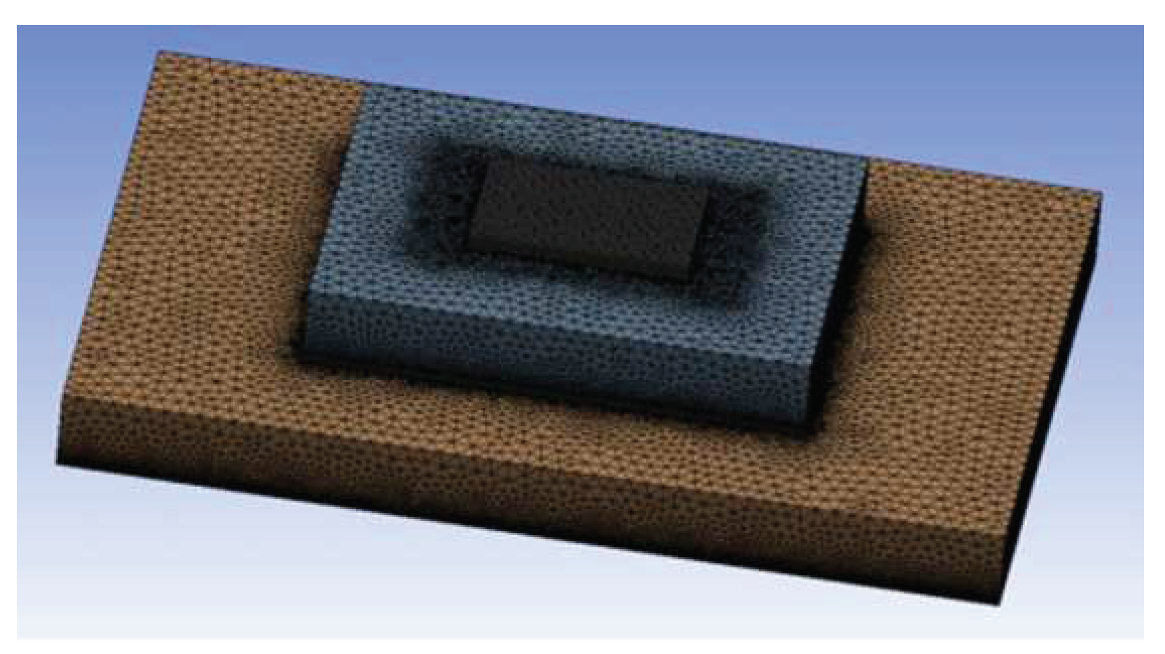
Figure 2.2. Enter the Mesh module for meshing. The mesh is encrypted and the resulting finite element model is shown in
Figure 3, containing a total of 8001646 mesh nodes and 17413469 mesh cells.
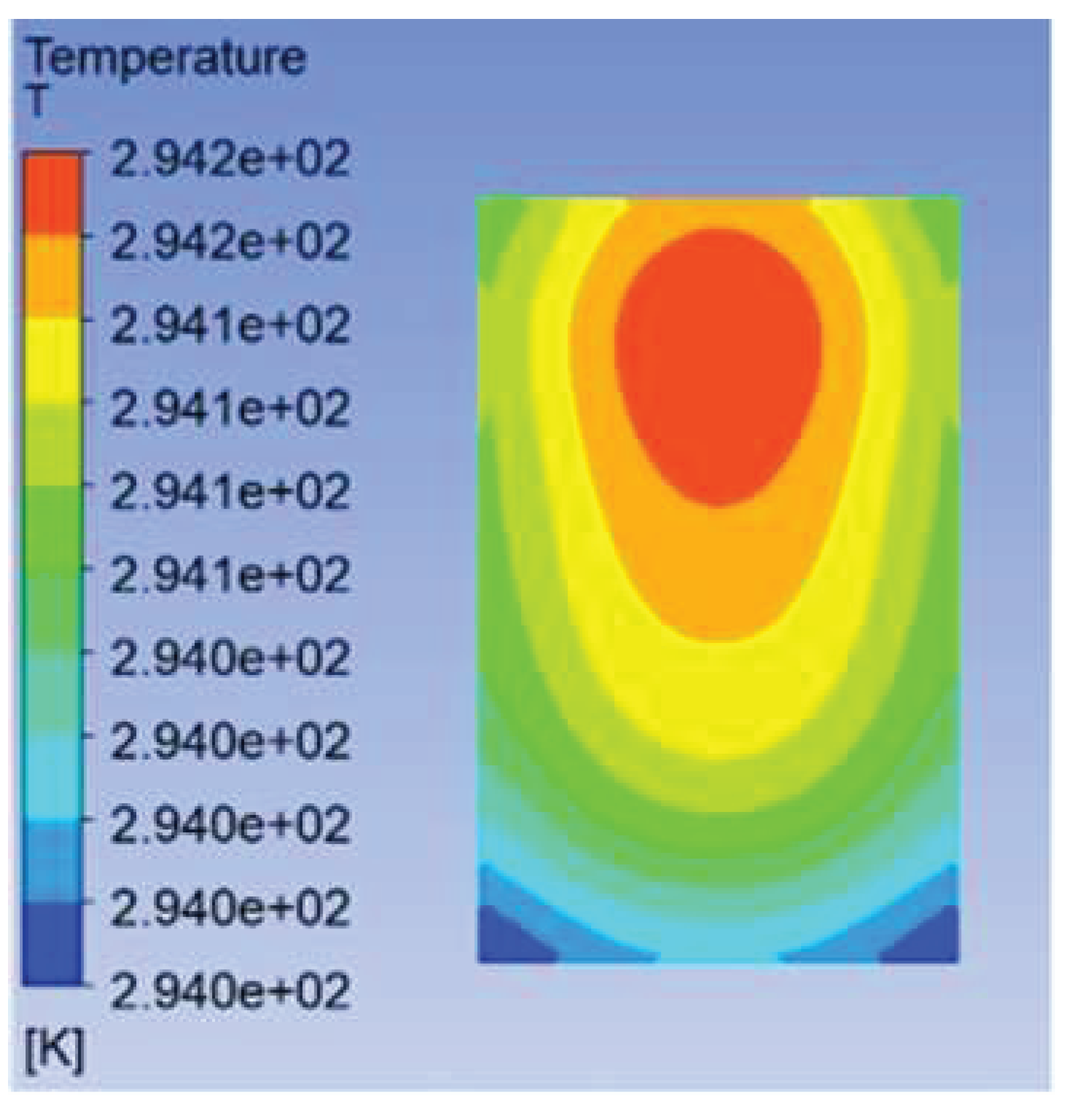
The solved temperature field of the chip is shown in
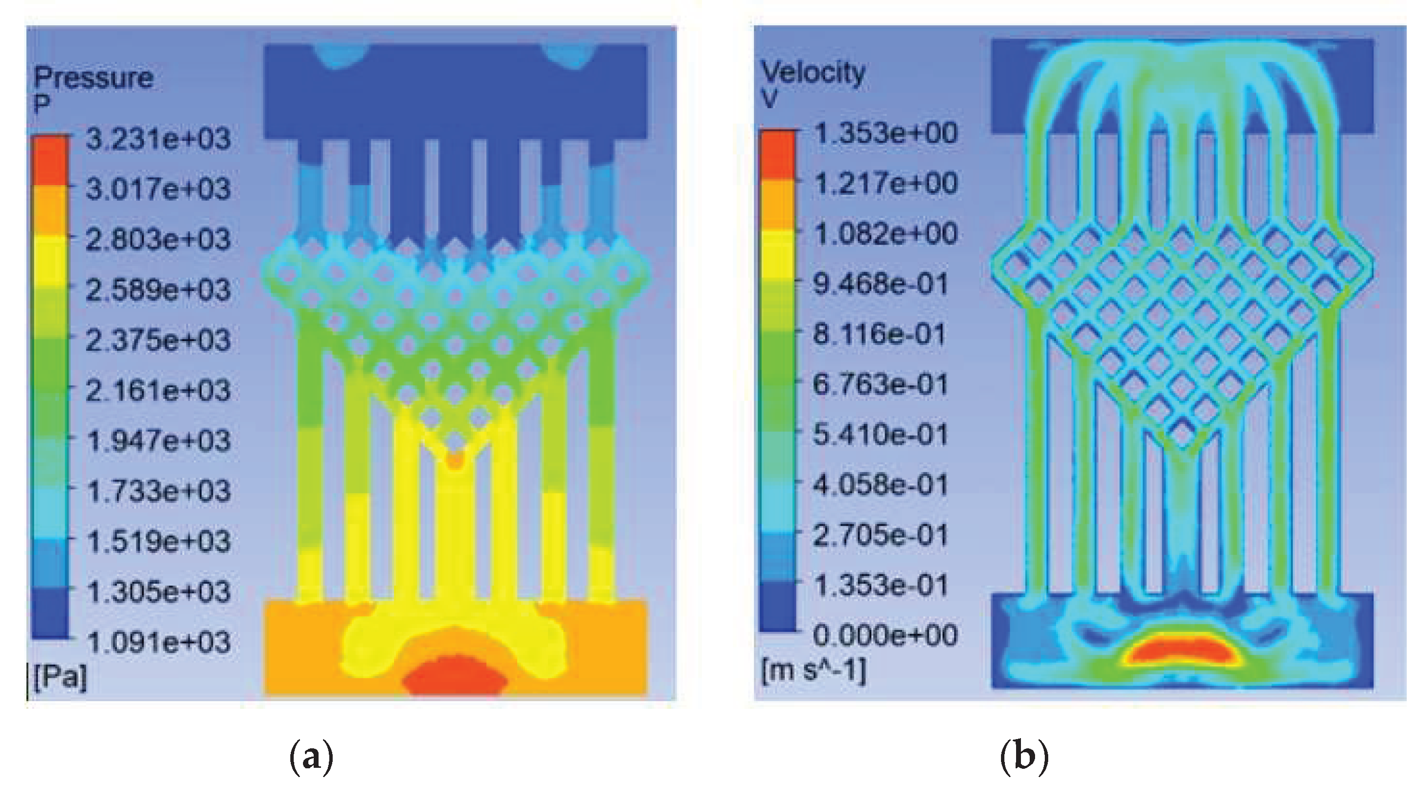
Figure 4, with a maximum chip temperature of 21.05°C. The maximum temperature of the chip is 21.05°C. The maximum temperature of the chip is 69.3% lower for the swept-back mesh embedded microchannel topology compared to the no-runner condition. The pressure and velocity fields of the flow path are shown in
Figure 5, which shows a pressure drop of 3231 Pa in the chip cooling flow path of SBFEMCT.
3.2. Analysis of the Effect of Flow Rate on the Heat Dissipation Effect of SBFEMCT
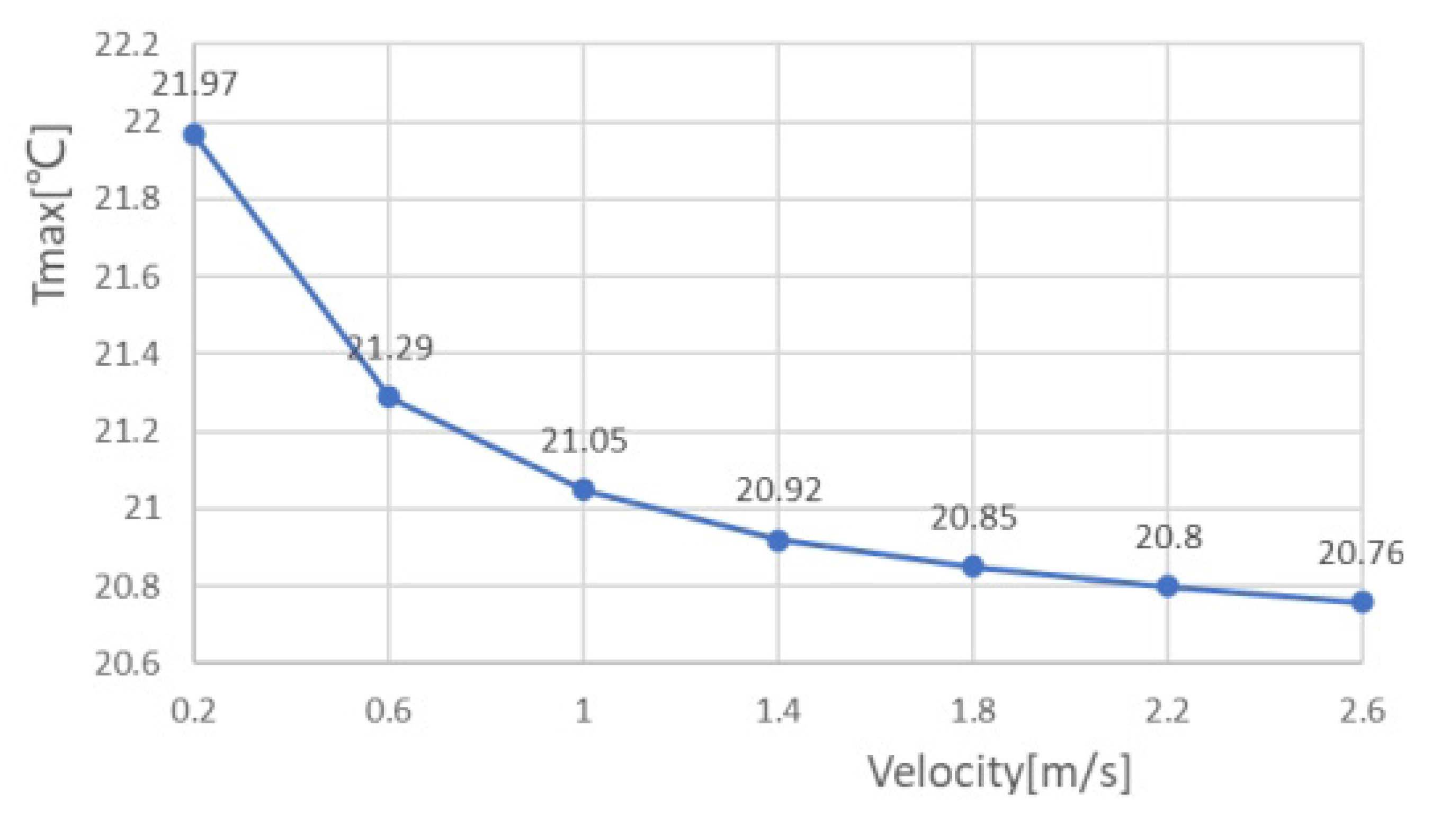
The coolant used in the model was aqueous, and the thermal performance of the model was analyzed by varying the inlet velocity value of the coolant. After meshing, the finite element model was obtained and Fluent was started according to the previous procedure, setting the heat flux of the chip to be the same as the no-fluid model, approximately 330 [W/cm3]. The pressure outlet is set to a relative static pressure of 0. The surfaces of both the substrate and the solder layer are set to adiabatic wall surfaces. The inlet temperature is set to 20 and the inlet flow rate is set from 0.2m/s ~ 2.6m/s to analyze the effect of flow rate on the heat dissipation effect of the chip embedded. The maximum chip temperature, maximum air pressure in the flow channel, and maximum flow rate at different flow rates were obtained as shown in
Table 2 and
Figure 6 shows the maximum chip temperature at different flow rates.
As the table shows, the maximum temperature of the chip gradually decreases as the velocity increases, and the maximum atmospheric pressure and maximum flow rate in the flow channel also increase. The temperature drops rapidly with velocity in the early stages, and then the maximum chip temperature tends to level off when the velocity is greater than 1.8m/s. This shows that the model can achieve a certain cooling effect by changing the flow rate of coolant when the flow rate is small, and the effect of speed on the cooling effect of the chip is not significant when the flow rate is large.
3.3. Analysis of the Effect of Mesh Density Ratio on the Heat Dissipation effect of SBFEMCT
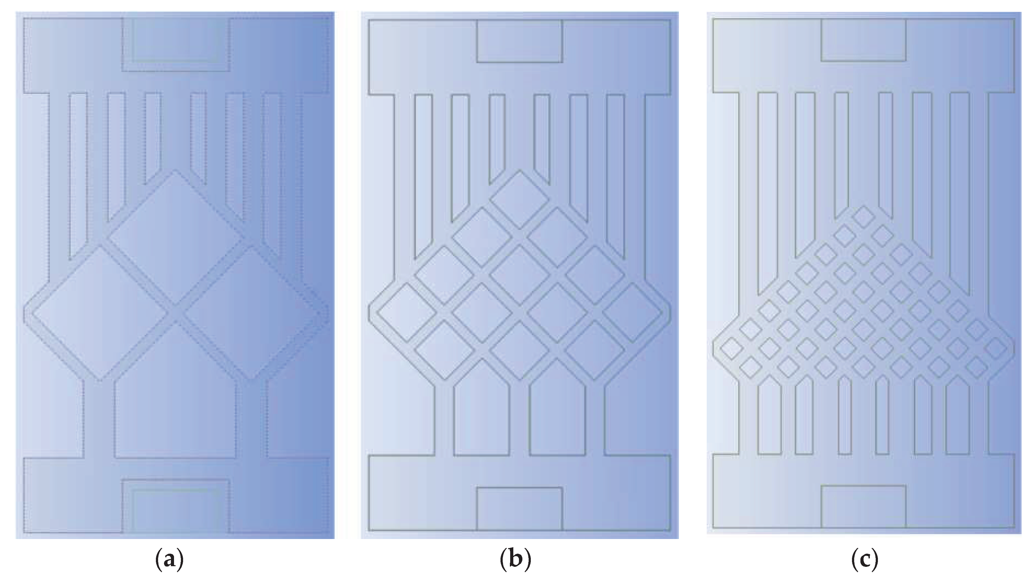
As the flow channel is symmetrical, the mesh density ratio of the mesh flow channel is defined as the inverse of the number of lattices in the top left-hand diagonal row of the mesh flow channel. For example, in the model in
Figure 4, there are eight lattices in the top left-hand diagonal row of the flow channel, so the mesh density ratio of the flow channel is 1/8 = 0.125.
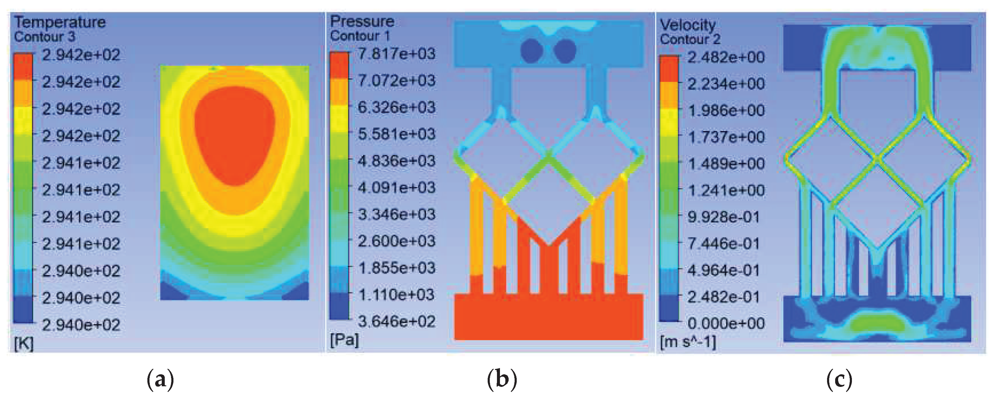
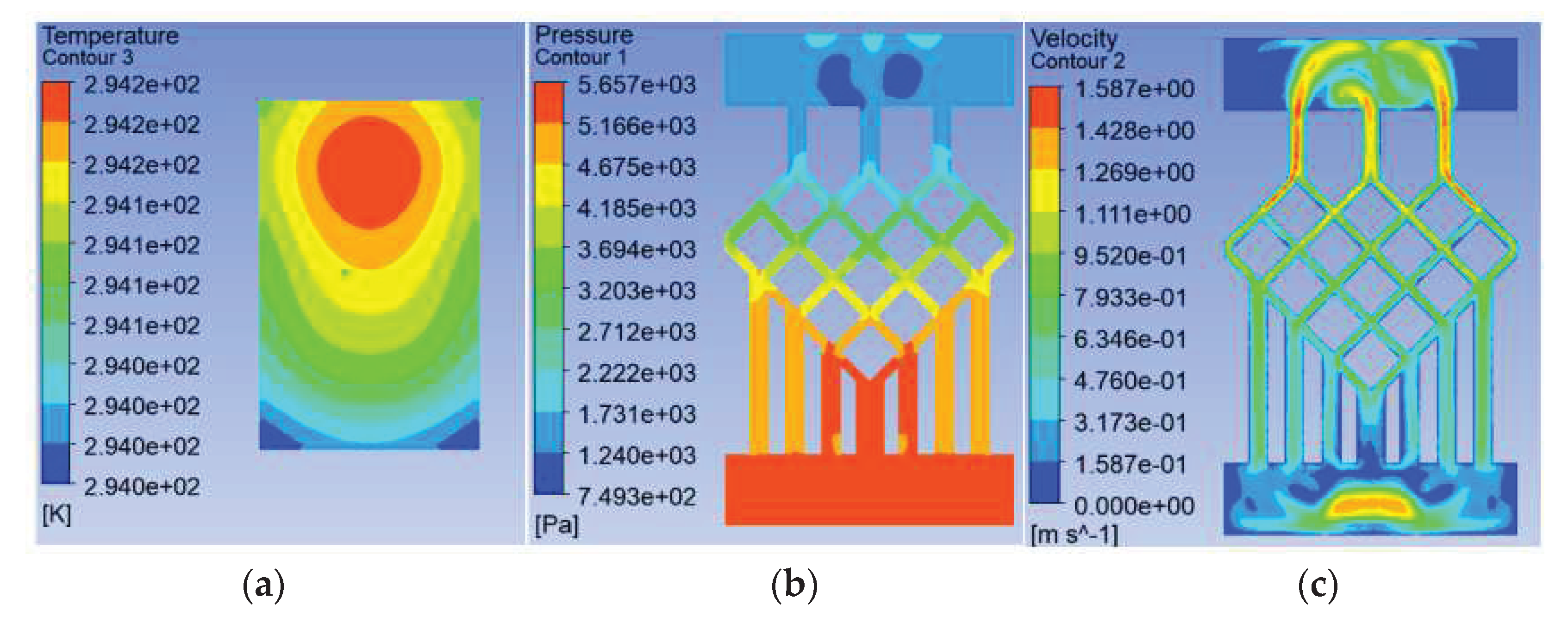
To study the effect of the mesh density ratio inside the mesh flow channel part of the model on the heat dissipation effect of the chip, four sets of flow channels with different mesh density ratios were designed without major changes to the overall shape of the mesh flow channel and with the same width of the mesh flow channel, namely, a mesh size of 0.9*0.9 with a density of 0.5, a mesh size of 0.4*0.4 with a density of 0.25, a mesh size of 0.15*0.15 with a density of 0.125, as shown in
Figure 7. The flow channel with a mesh size of 0.15*0.15 and a density of 0.125 is the model shown in
Figure 2, and its results are shown in
Figure 4 and
Figure 5. And their results are shown in
Figure 8 and
Figure 9. The flow and heat transfer characteristics were simulated at an inlet velocity of 1.0 and the parameters obtained are shown in
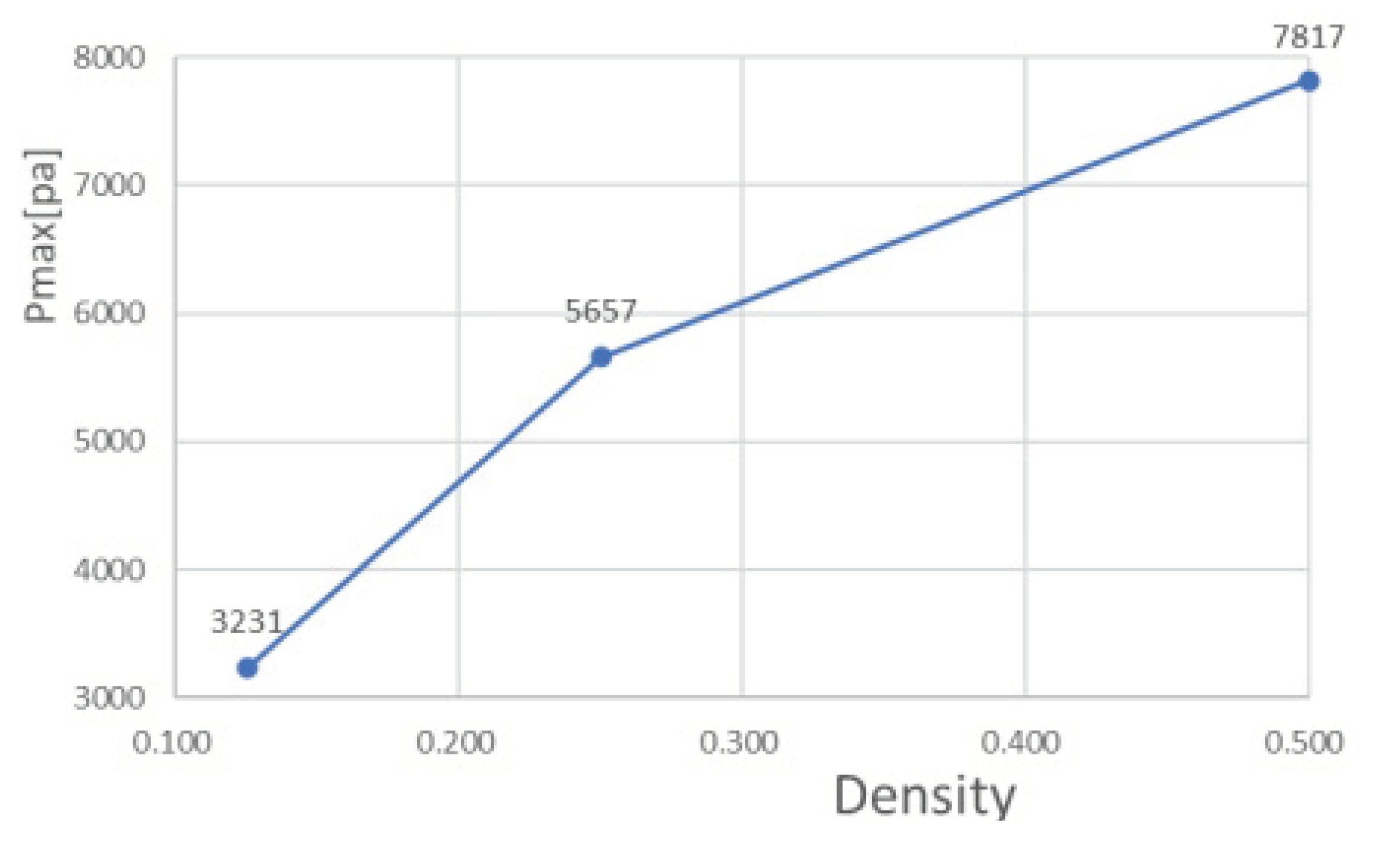
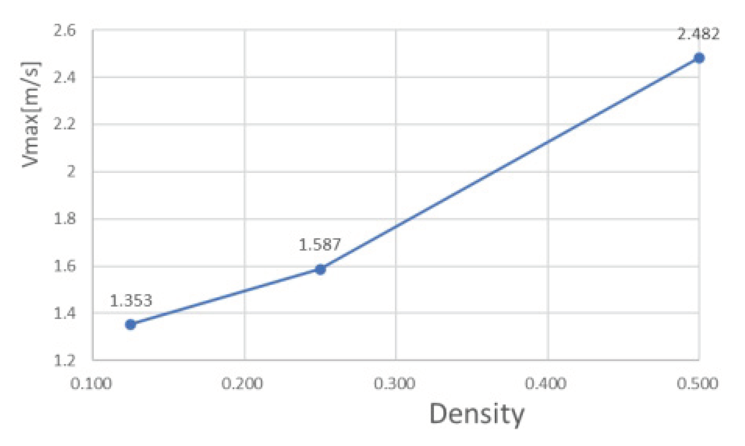
Table 3. The maximum pressure drop and maximum velocity of the flow channel were chosen as the characterization objects, as shown in
Figure 10 and
Figure 11.
It can be seen from Fig. 10 and Fig. 11 that the smaller the mesh density ratio, the lower the maximum pressure drop and the higher the maximum flow rate in the flow channel, but the change in mesh density ratio is negligible about the maximum chip temperature. The Pmax for a grid density ratio of 0.25 is 72.37% of the Pmax for a grid density ratio of 0.5 and the Pmax for a grid density ratio of 0.125 is 57.12% of the Pmax for a grid density ratio of 0.25. Vmax at a mesh density ratio of 0.25 is 117.3% of Vmax at a mesh density ratio of 0.5 and Vmax at a mesh density ratio of 0.125 is 156.4% of Vmax at a mesh density ratio of 0.25. As the width of the fishnet runner remains the same, the fishnet runner only changes the size of the rhombus in it, so the smaller the mesh density ratio, the smaller the rhombus and the more internal runners in the fishnet runner section. So the smaller the area of coolant obstructed in the mesh flow channel, this leads to lower a maximum pressure drop and a lower maximum flow rate. In the abstract, refining the mesh and reducing the mesh density ratio can effectively reduce the pressure drop and flow velocity within the flow channel.
3.4. Analysis of the Effect of the Number of Fishnet Runner Layers on the Heat Dissipation Effect of SBFEMCT
Due to the high alignment of the rhombic lattice, the mesh flow channel has a high degree of ductility throughout the flow channel. Specifically, the mesh can be extended or contracted in the longitudinal direction with the same number of longitudinal straight runners, grid density ratio, and mesh width.
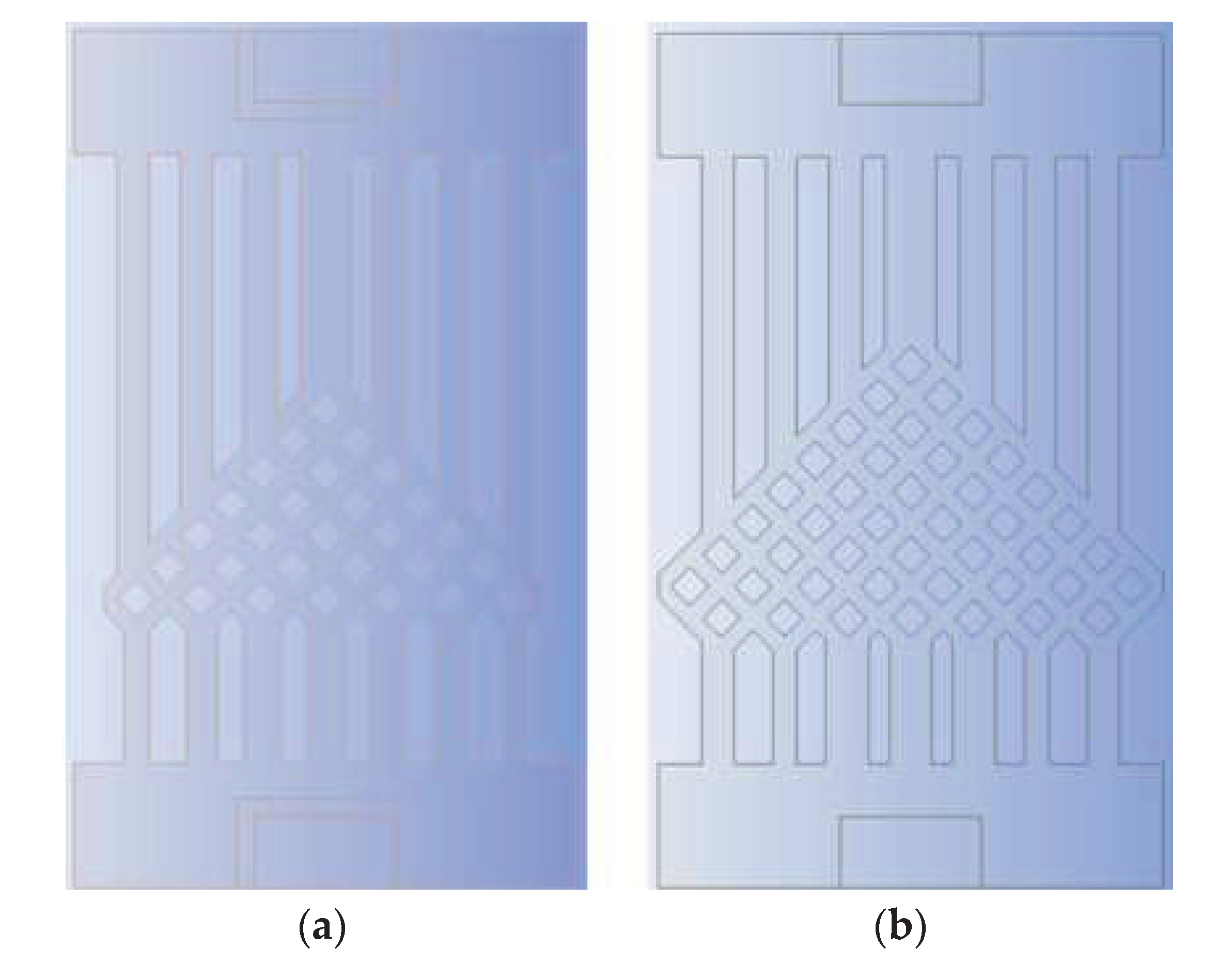
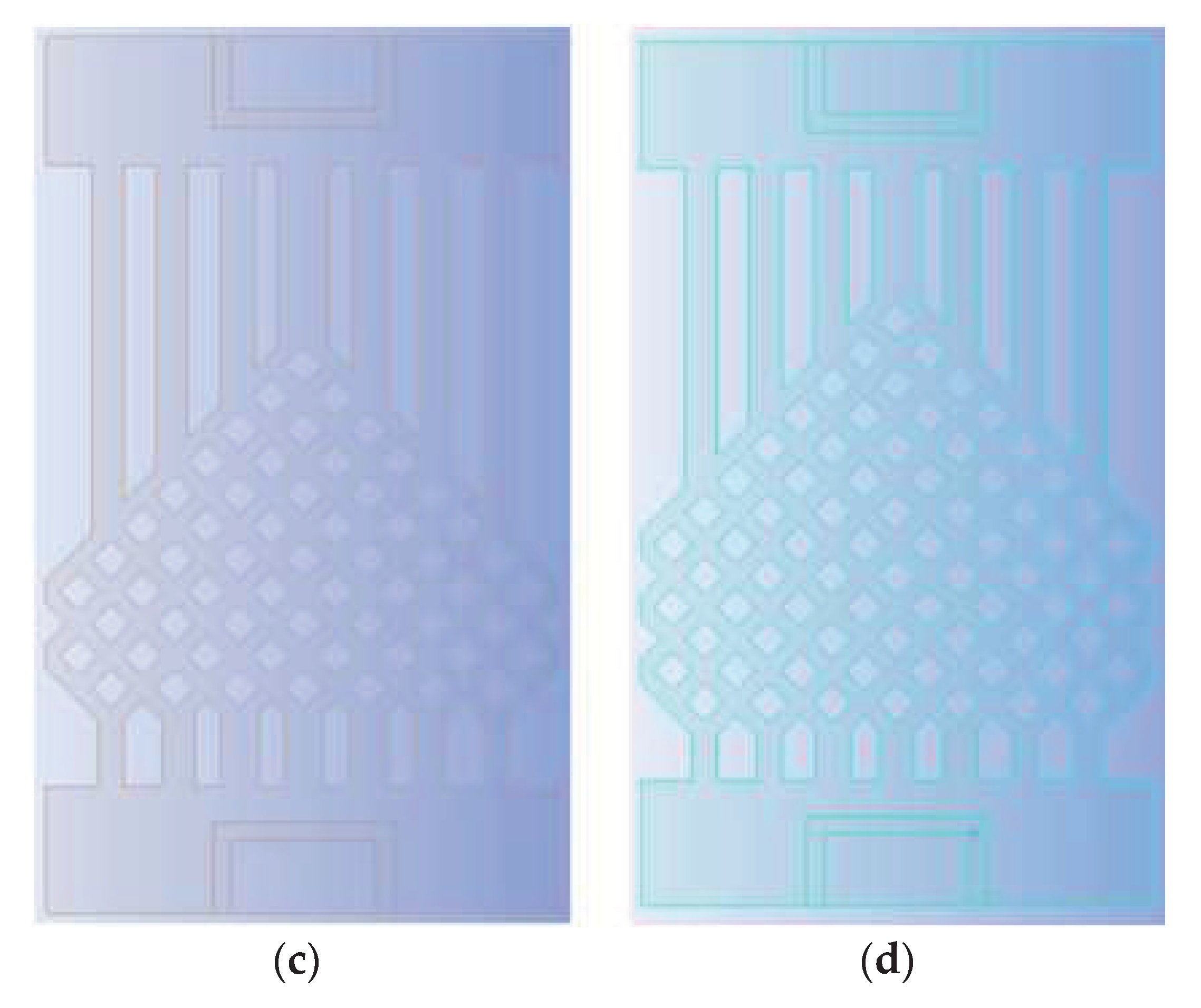
Since the runner is symmetrical from left to right as a whole, the number of fishnet runner layers is defined in this paper as the number of rhombuses beyond the fourth straight runner from the center to the left. As in the model in
Figure 2, the number of rhombuses in the lower left part of the flow channel beyond the fourth longitudinal straight flow channel from the center to the left is 1, so the number of layers in the flow channel is 1.
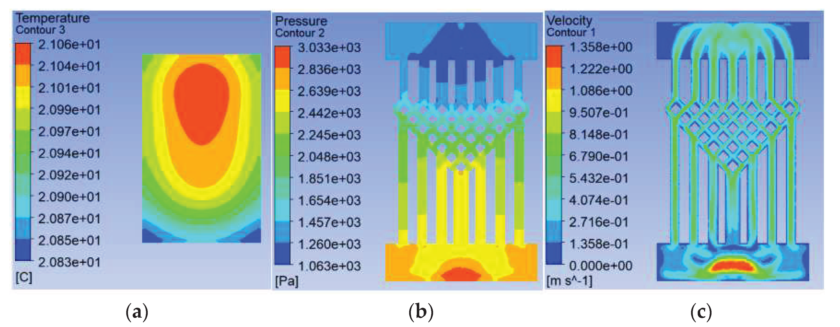
To investigate the effect of the ratio of the fishnet-like flow compared to the overall flow channel in the model on the heat dissipation effect of the chip, four sets of flow channels with different numbers of fishnet-like flow channel layers were designed, which are the flow channels with 0, 1, 2 and 3 fishnet-like flow channel layers, as shown in
Figure 12, and its results are shown in
Figure 4 and
Figure 5. The flow channel with 1 fishnet-like flow channel layer is the model shown in
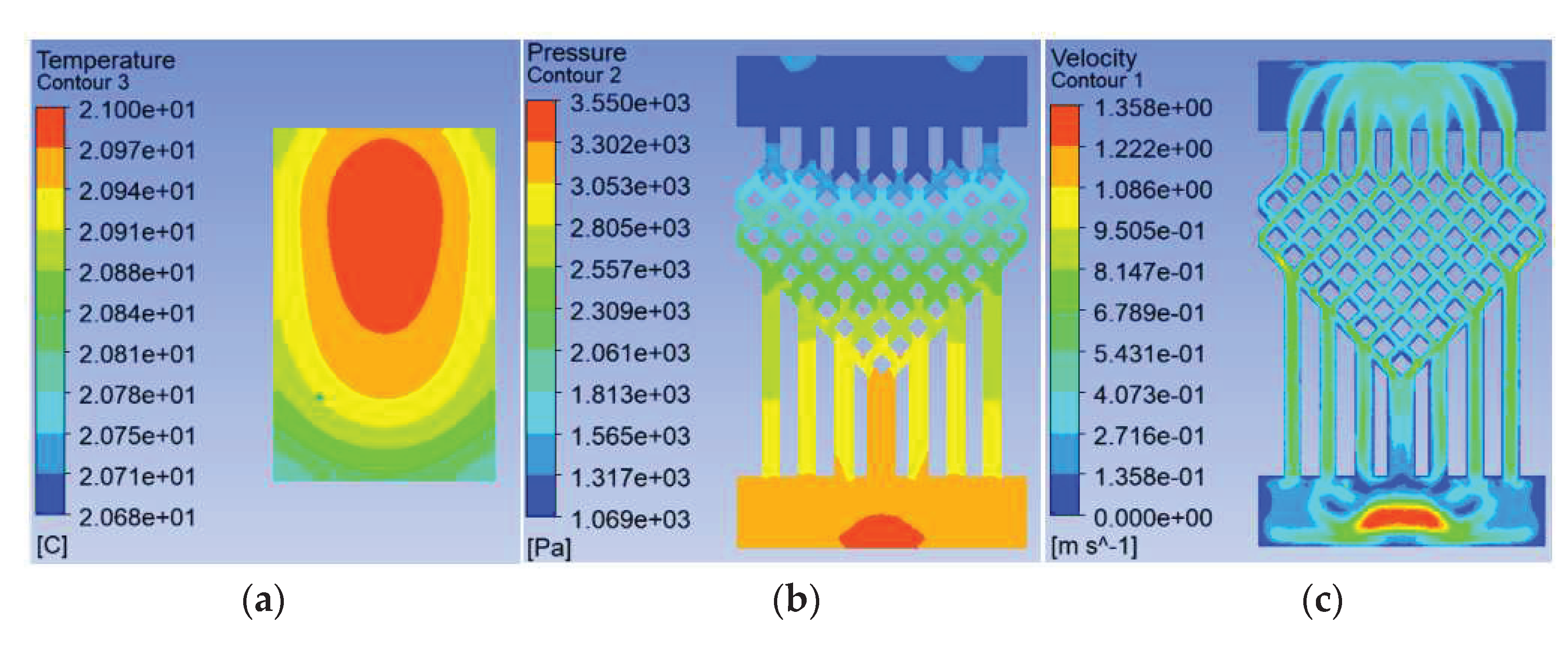
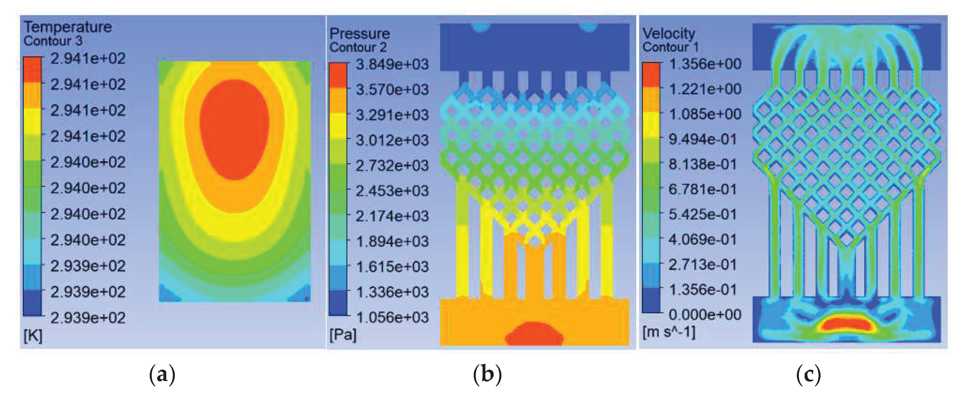
Figure 2. The results for fishnet-like runner layers of 0, 2 and 3 are shown in
Figure 13,
Figure 14 and
Figure 15.
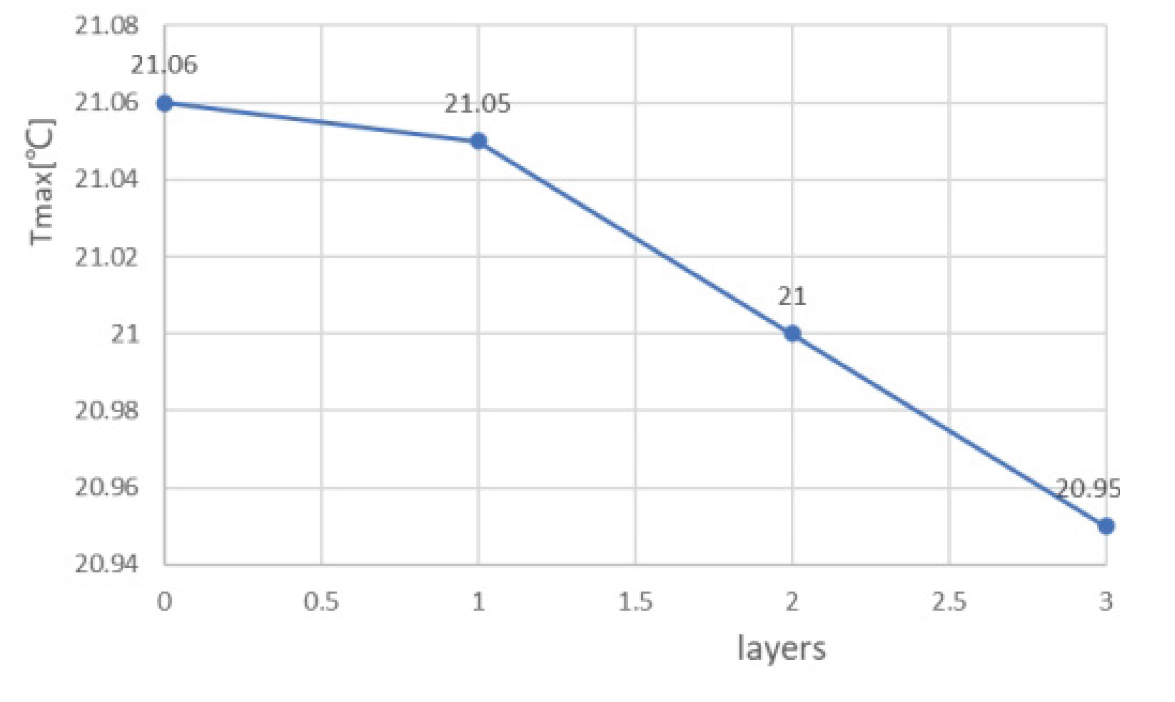
In the analysis of the effect on cooling in this section, the distribution of the fishnet runners in all four models follows one principle - the upper third of the splitting point on the seam line in the fishnet runner is placed in the center of the entire runner. This is used to ensure that the highest temperatures, in and around the center of the chip, are disturbed more so that the temperature in this area is better brought out and a cooling effect is achieved. The flow and heat transfer characteristics were simulated at an inlet velocity of 1.0 and the parameters obtained are shown in
Table 4. The highest chip temperature was chosen as the object of characterization, as shown in
Figure 16.
It can be seen from Fig. 16 that the higher the number of layers of the mesh flow channel, the lower the maximum temperature of the chip, the smaller the maximum pressure drop in the flow channel, and the maximum flow rate is basically unchanged. This is because the maximum temperature is too close to the inlet temperature and the maximum temperature cannot be lower than the inlet temperature, so the reduction in temperature is not obvious. The increase in the number of layers in the flow channel increases the Pmax by approximately 300 Pa. The more layers in the flow channel, the more the coolant is disturbed and mixed in the flow channel, increasing the influence on the heat exchange layer in the microchannel and thus reducing the maximum chip temperature. In the abstract, increasing the number of layers in the flow channel reduces the maximum chip temperature, increases the maximum pressure drop, and has little effect on the maximum flow rate.
4. Conclusion
This paper proposes a novel swept-back fishnet-embedded microchannel topology (SBFEMCT) from the dimension of a single chip based on the truncated microchannel structure in the literature [
7]. The feasibility and plasticity of BSFEMCT are explored in terms of varying the fishnet-like flow channel mesh density ratio and the number of fishnet-like flow channel layers, which can be summarized as follows.
Reducing the mesh density ratio effectively reduces the pressure drop and flow velocity in the flow channel. The mesh density ratio decreases from 0.5 to 0.25, and Pmax decreases from 7817 to 5657, the latter being 72.37% of the former; Vmax increases from 1.353 to 1.587, the latter being 117.0% of the former. The mesh density ratio decreased from 0.25 to 0.125, Pmax from 5657 to 3231, the latter being 57.12% of the former; Vmax increased from 1.587 to 2.482, the latter being 156.4% of the former.
Increasing the number of layers of the mesh flow channel results in a general reduction in maximum temperature, little change in maximum velocity, and a small increase in maximum pressure drop. The Pmax increases by approximately 300 Pa for each additional layer of the mesh flow channel.
All the research carried out in this paper does not involve knowledge of circuits, microelectronics, etc. for the time being. Based on the success of the research in this paper, further work can be carried out on:
The research in this paper is still at the simulation and analysis stage and has not yet entered the processing experiment stage. As embedded cooling is the direct pumping of the cooling mass into the chip for heat dissipation, embedded cooling has a higher heat dissipation efficiency and at the same time places more demanding requirements on the microfabrication process and packaging capabilities.
The chip’s heat source is a large number of high electron mobility transistors, which in this paper is simplified to a uniform heat-generating square. In later work, this can be modeled in detail, closer to the actual operating conditions, and its engineering significance will be greater. Accordingly, the thermal structure will need to be designed separately and may be less versatile.
The thermal structures in this paper can all be further analyzed and optimized. For example, the widths of the runner entrances and exits can be refined, the widths of the fishnet-like runners can be refined, and the number of flat microchannels in the entrance and exit sections can be refined.
Author Contributions
Conceptualization, Y.W. and X.Z.; methodology, Y.W. and X.Z.; software, X.Z. and X.Y.; validation, X.Z., X.Y. and Y.Y.; formal analysis, X.Z. and Z.W.; investigation, X.Z.; resources, X.Z., B.D. and J.Z; writing—original draft preparation, X.Z.; writing—review and editing, Y.W. and X.Z.; visualization, X.Z.; supervision, C.W.; funding acquisition, Y.W. and C.W. All authors have read and agreed to the published version of the manuscript.
Funding
This work was supported by National Natural Science Foundation of China under No. 52105272 and 51975447, Youth Science and Technology Star Project of Shaanxi Province under No. 2023KJXX-044, National Defense Basic Scientific Research Program of China under No. JCKY2021210B007, Wuhu and Xidian University Special Fund for Industry-University-Research Cooperation under No. XWYCXY-012021012.
Data Availability Statement
The data presented in this study are available on request from the corresponding author.
Conflicts of Interest
The authors declare no conflict of interest.
Nomenclature
|
cp,f
|
specific heat capacity of the fluid (J/(kg⋅℃)) |
| P |
Pressure (Pa) |
| T |
temperature (℃) |
| u |
velocity (m/s) |
| k |
thermal conductivity (W/(m⋅℃)) |
| Subscript |
|
| max |
maximum |
| min |
minimum |
| f |
fluid |
| s |
solid |
| Green letters |
|
| μ |
dynamic viscosity (Pa⋅s) |
| ρ |
density (kg/m3) |
References
- He Lichen, Hong Yuan, Yang Liming, Chi Baihong. Research progress of active phased array radar antenna cooling technology[J]. Spacecraft Environmental Engineering 2022, 39, 316–325. [Google Scholar]
- Yang, X.; Lin, K.; Zhang, D.; Liu, S.; Han, B.; Wang, Z.; Yu, K.; Wu, W.; Ge, D.; Wang, C. A Novel Manifold Dual-Microchannel Flow Field Structure with High-Performance Heat Dissipation. Micromachines 2022, 13, 1420. [Google Scholar] [CrossRef] [PubMed]
- Wang, Y.; Wang, C.; Lian, P.; Xue, S.; Liu, J.; Gao, W.; Shi, Y.; Wang, Z.; Yu, K.; Peng, X.; Du, B.; Xiao, S. Effect of Temperature on Electromagnetic Performance of Active Phased Array Antenna. Electronics 2020, 9, 1211. [Google Scholar] [CrossRef]
- Liu, S.; Yan, Y.; Zhou, Y.; Han, B.; Wang, B.; Zhang, D.; Xue, S.; Wang, Z.; Yu, K.; Shi, Y.; Wang, C. Thermal Induced Interface Mechanical Response Analysis of SMT Lead-Free Solder Joint and Its Adaptive Optimization. Micromachines 2022, 13, 908. [Google Scholar] [CrossRef] [PubMed]
- Chen, H.; Chen, C.; Zhou, Y.; Yang, C.; Song, G.; Hou, F.; Jiao, B.; Liu, R. Evaluation and optimization of a cross-rib micro-channel heat sink. Micromachines 2022, 13, 132. [Google Scholar] [CrossRef] [PubMed]
- Peng, M.; Chen, L.; Ji, W.; Tao, W. Numerical study on flow and heat transfer in a multi-jet microchannel heat sink. International Journal of Heat and Mass Transfer 2020, 157, 119982. [Google Scholar] [CrossRef]
- Li, Chao-Ting. Embedded thermal design of high power array antenna[D]. Xi'an University of Electronic Science and Technology, 2022. (in Chineses).
- Bar-Cohen1, J. J. Maurer1, D. H. Altman. Gen3 Embedded Cooling for High Power RF Components[C]. IEEE International Conference on Microwaves, Antennas, Communications and Electronic Systems, Tel-Aviv, Israel, 2017. IEEE. 2018.
- Li Zheng, Yue Zhang and Muhannad S. Bakir. Design, Fabrication and Assembly of a Novel Electrical and Microfluidic I/Os for 3-D Chip Stack and Silicon Interposer[C]. IEEEE Electronic Components & Technology Conference. 2013, 2243-2247.
- John Ditr, Joseph Hahn, Roland Cadotte, Michael McNulty, Denise Luppa. Embedded cooling of high heat flux electronics utilizing distributed microfluidic impingement jets[C]. Proceedings of the ASME 2015 International Technical Conference and Exhibition on Packaging and Integration of Electronic and Photonic Microsystems. San Francisco, California, USA ,2015:1-6.
- Remco van Erp, Georgios Kampitsis, Luca Nela, et al. Embedded Microchannel Cooling for High Power-Density GaN-on-Si Power Integrated Circuits[C]. IEEE ITHERM Conference , 2020, 53-56.
- Remco van Erp, Reza Soleimanzadeh, Luca Nela, et al. Co-designing electronics with microfluidics for more sustainable cooling[J]. Nature, 2020, 585, 211–216.
- Remco van Erp, Nirmana Perera, Luca Nela, et al. Embedded Microchannel Cooling for Monolithically-integrated GaN Half-bridge ICs[J]. 2021 27th International Workshop on Thermal Investigations of ICs and Systems (THERMINIC), 2021. 2021.
- Miao Siyuan. Key technologies for efficient heat dissipation of high-power active phased array antennas [D]. Xi'an University of Electronic Science and Technology. 2021.
- İzci T, Koz M, Koşar A. The effect of micro pin-fin shape on thermal and hydraulic performance of micro pin-fin heat sinks[J]. Heat Transfer Engineering 2015, 36, 1447–1457. [Google Scholar] [CrossRef]
- Dewan A, Srivastava P. A review of heat transfer enhancement through flow disruption in a microchannel[J]. Journal of Thermal Science 2015, 24, 203–214. [Google Scholar] [CrossRef]
- XU Guoqiang, WANG Meng, WU Hong, TAO Zhi. Numerical analysis of the heat transfer characteristics of Y-shaped configuration microchannel flow[J]. Journal of Beijing University of Aeronautics and Astronautics, 2009, (in Chinese).
Figure 1.
Schematic diagram of the secondary circulation of the spiral tube fluid.
Figure 1.
Schematic diagram of the secondary circulation of the spiral tube fluid.
Figure 2.
Back-swept fishnet-like embedded microchannel topology.
Figure 2.
Back-swept fishnet-like embedded microchannel topology.
Figure 3.
Finite element model of a Fishnet recessed topological structure chip.
Figure 3.
Finite element model of a Fishnet recessed topological structure chip.
Figure 4.
SBFEMCT chip temperature field.
Figure 4.
SBFEMCT chip temperature field.
Figure 5.
SBFEMCT flow channel pressure and velocity fields , they should be listed as: (a) pressure field; (b) velocity field.
Figure 5.
SBFEMCT flow channel pressure and velocity fields , they should be listed as: (a) pressure field; (b) velocity field.
Figure 6.
Maximum temperature of the chip at different velocities.
Figure 6.
Maximum temperature of the chip at different velocities.
Figure 7.
Different mesh density ratio, they should be listed as: (a) The mesh density ratio is 0.500; (b) The mesh density ratio is 0.250; (c) The mesh density ratio is 0.125.
Figure 7.
Different mesh density ratio, they should be listed as: (a) The mesh density ratio is 0.500; (b) The mesh density ratio is 0.250; (c) The mesh density ratio is 0.125.
Figure 8.
Results for a mesh density ratio of 0.500, they should be listed as: (a) Temperature field at the chip; (b) Pressure field at the runner; (c) Velocity field at runners.
Figure 8.
Results for a mesh density ratio of 0.500, they should be listed as: (a) Temperature field at the chip; (b) Pressure field at the runner; (c) Velocity field at runners.
Figure 9.
Results for a mesh density ratio of 0.250, they should be listed as: (a) Temperature field at the chip; (b) Pressure field at the runner; (c) Velocity field at runners.
Figure 9.
Results for a mesh density ratio of 0.250, they should be listed as: (a) Temperature field at the chip; (b) Pressure field at the runner; (c) Velocity field at runners.
Figure 10.
Maximum pressure drop in flow channels at different mesh densities.
Figure 10.
Maximum pressure drop in flow channels at different mesh densities.
Figure 11.
Maximum velocity in flow channels at different mesh densities.
Figure 11.
Maximum velocity in flow channels at different mesh densities.
Figure 12.
Different Fishnet Runner Layers, they should be listed as: (a) The number of layers in the fishnet runner is 0; (b) The number of layers in the fishnet runner is 1; (c) The number of layers in the fishnet runner is 2; (d) The number of layers in the fishnet runner is 3.
Figure 12.
Different Fishnet Runner Layers, they should be listed as: (a) The number of layers in the fishnet runner is 0; (b) The number of layers in the fishnet runner is 1; (c) The number of layers in the fishnet runner is 2; (d) The number of layers in the fishnet runner is 3.
Figure 13.
Results when the number of layers of fishnet-like runners is 0, they should be listed as: (a) Temperature field at the chip; (b) Pressure field at the runner; (c) Velocity field at runners.
Figure 13.
Results when the number of layers of fishnet-like runners is 0, they should be listed as: (a) Temperature field at the chip; (b) Pressure field at the runner; (c) Velocity field at runners.
Figure 14.
Results when the number of layers of fishnet-like runners is 2, they should be listed as: (a) Temperature field at the chip; (b) Pressure field at the runner; (c) Velocity field at runners.
Figure 14.
Results when the number of layers of fishnet-like runners is 2, they should be listed as: (a) Temperature field at the chip; (b) Pressure field at the runner; (c) Velocity field at runners.
Figure 15.
Results when the number of layers of fishnet-like runners is 3, they should be listed as: (a) Temperature field at the chip; (b) Pressure field at the runner; (c) Velocity field at runners.
Figure 15.
Results when the number of layers of fishnet-like runners is 3, they should be listed as: (a) Temperature field at the chip; (b) Pressure field at the runner; (c) Velocity field at runners.
Figure 16.
Maximum chip temperature for different layers of fishnet runners.
Figure 16.
Maximum chip temperature for different layers of fishnet runners.
Table 1.
Materials and their parameters.
Table 1.
Materials and their parameters.
| Material type |
Chemical formula |
ρ |
Cp,f |
Heat conductivity
[W/(m K)] |
Viscosity
[kg/(m s)] |
| solid |
sn63_pb73 |
8400 |
280 |
10 |
/ |
| si |
2300 |
700 |
150 |
| htcc |
3900 |
205 |
20 |
| ga_as |
5300 |
325 |
45 |
| au_sn |
14700 |
150 |
57 |
| fluid |
h2o<1> |
998.2 |
4182 |
0.6 |
0.001003 |
Table 2.
Effect of different speeds on heat dissipation in SBFEMCT.
Table 2.
Effect of different speeds on heat dissipation in SBFEMCT.
| V |
Tmax |
Pmax |
Vmax |
| 0.2 |
21.97 |
308.8 |
0.2971 |
| 0.6 |
21.29 |
1412 |
0.8491 |
| 1.0 |
21.05 |
3231 |
1.353 |
| 1.4 |
20.92 |
5761 |
1.869 |
| 1.8 |
20.85 |
8935 |
2.376 |
| 2.2 |
20.8 |
12920 |
2.942 |
| 2.6 |
20.76 |
17650 |
3.509 |
Table 3.
Heat dissipation data for different grid densities at a speed of 1.0.
Table 3.
Heat dissipation data for different grid densities at a speed of 1.0.
| Rhombus size |
Density |
Tmax |
Pmax |
Vmax |
| 0.9*0.9 |
0.500 |
21.05 |
7817 |
2.482 |
| 0.4*0.4 |
0.250 |
21.05 |
5657 |
1.587 |
| 0.15*0.15 |
0.125 |
21.05 |
3231 |
1.353 |
Table 4.
Heat dissipation data for different layers of fishnet runner at a speed of 1.0.
Table 4.
Heat dissipation data for different layers of fishnet runner at a speed of 1.0.
| layers |
Tmax |
Pmax |
Vmax |
| 0 |
21.06 |
3033 |
1.358 |
| 1 |
21.05 |
3231 |
1.353 |
| 2 |
21.00 |
3550 |
1.358 |
| 3 |
20.95 |
3849 |
1.356 |
|
Disclaimer/Publisher’s Note: The statements, opinions and data contained in all publications are solely those of the individual author(s) and contributor(s) and not of MDPI and/or the editor(s). MDPI and/or the editor(s) disclaim responsibility for any injury to people or property resulting from any ideas, methods, instructions or products referred to in the content. |
© 2023 by the authors. Licensee MDPI, Basel, Switzerland. This article is an open access article distributed under the terms and conditions of the Creative Commons Attribution (CC BY) license (http://creativecommons.org/licenses/by/4.0/).
