Preprint
Article

Aerodynamic Characteristics of Different Heights Buildings in Close Proximity

Altmetrics

Downloads

118

Views

28

Comments

0

Submitted:

28 June 2023

Posted:

29 June 2023

You are already at the latest version

Alerts
Abstract
The close proximity of different buildings heights can cause disturbances in the working of the smoke and ventilation ducts of lower buildings, threatening the health and even the lives of residents. To define the influence of high-rise building on the work of the ducts of the neighbouring double-storied building, experimental investigations in the wind tunnel were conducted. On this basis, empirical equations and graphs were developed leading to determining the aerodynamic coefficients considering different wind directions and the height of ducts. The direction of the wind reveals a greater influence than the height of the ducts. Properly using deflectors or increasing the height of the duct ensures maintaining static rarefaction in the area of smoke and ventilation ducts. The creation of rarefaction ensures the reliability of the natural ventilation system and the safety of the health of residents.
Keywords: 
Subject: Engineering  -   Civil Engineering

1. Introduction

The proper microclimate [1,2,3,4,5] in the room is provided by heating and natural or mechanical ventilation systems [6,7,8] with compliance with energy savings requirements [9,10,11,12]. The base element in the natural ventilation system is usually a duct in the premises, which is led above the roof of the building. Air exchange occurs due to the movement of air caused by the difference in temperature inside and outside the building, and in a ventilation duct in a pressure (draft) increases in proportion to the height of the it. When the ventilation duct creates a draft, it causes the air pressure in the room to decrease, which is known as rarefaction. The decrease in air pressure causes air to flow from areas of higher pressure to areas of lower pressure, circulating fresh air throughout the room. If the room has suitable openings for the flow of outside air, then with a sufficient temperature difference between the inside and outside air, the necessary air exchange is achieved [13]. Under conditions of the same internal and external air temperature and in the absence of wind, air movement in the ventilation duct is impossible. This phenomenon is observed in summer. In addition, in the case of the higher value of the external air temperature in comparison to internal air temperature, a change in the direction of air movement in the duct appears, i.e., to the phenomenon of "a back draft". The consequence of this is the inability of ventilation to perform its function, affecting the air quality in the room, and causing pollutants (such as cigarette smoke, paint fumes, etc.) to be removed more slowly from the room, leading to higher concentrations of these substances in the air and a threat to the health and sometimes the life of the residents. The problem is solved by opening windows [14].
In winter, the difference in pressure between indoor and outdoor air is important. The pressure of the outside air is determined by static and, most of all, dynamic pressure. It depends on the wind speed at a certain point in space, the direction of the wind, and the presence of vortices on the windward and leeward facades of the building.
To increase the efficiency of natural ventilation nozzles (deflectors) at the top of the duct are installed increasing under pressure, however, in the absence of wind, they are the additional aerodynamic resistance. The effectiveness of these nozzles is different and depends on the speed and direction of the wind [15,16].
An additional problem with the efficiency of natural ventilation is the result of ignoring the required distances between newly built buildings, especially with different heights [17]. When low-rise residential blocks are constructed in close proximity to high-rise buildings (or conversely), the proper distances are not always ensured [18,19,20]. This fact leads to the work deterioration of the smoke and ventilation ducts of low-rise buildings. This should be avoided, as it also negatively affects the health residents.
This research topic is closely related to urban planning, as it examines the aerodynamics of wind flow around buildings and the impact of high-rise buildings on low-rise buildings located next to each other in residential neighborhoods. This issue is relevant both at the stage of reconstruction of existing buildings and at the stage of designing new ones.
The purpose of the work is to identify the aerodynamic influence of the 9-storied building with close location on the operation of the smoke and ventilation ducts of a double-storied residential building. Aerodynamic coefficients under different wind directions of low-rise building are determined, as well as analytical and graphic dependencies are established.

2. Materials and Methods

2.1. Theoretical background

The wind, flowing around the building, creates positive and negative pressures on its surface [21,22,23]. Disturbances introduced into the flow (distortion of the flow lines around the building) cover a relatively small area [24,25]. Outside this area, the streamlines remain the same as if there were no building in the flow. At a distance of approximately 5 to 8 heights of the building from the windward side, the surface layers of air slow down, part of the kinetic energy of the wind flow turns into potential energy, as a result of which the static pressure pst in front of the building increases. The static pressure reaches its maximum value on the surface of the windward facade. The incoming air flow forms a vortex zone in front of the building, the shape of which seems to complement the shape of the building to a conveniently streamlined one, thereby reducing the energy loss of the potential (undisturbed) flow. The building is flown by wind from above and from the sides, so in these places there is some compression of the main flow and an increase in its speed compared to the speed of the undisturbed flow. For this reason, the air on the leeward facade of the building is constantly ejected by the main flow, and the pressure on the leeward facade is constantly reduced. Replenishment of the ejected air takes place due to the surface layers, which are inhibited, can change direction, carry out a vortex movement and flow from the area of increased pressure to the under-pressure zone. On the windward side there is a stagnation zone (aerodynamic wake zone) [26]. The length of this zone is taken from the condition that the speed of the flow in it is at least 95% of the speed of the undisturbed flow at the same height from the surface of the earth. In the inner region of the aerodynamic wake, there is a circulation zone (aerodynamic shadow zone), within which reverse air flows are observed. For a free-standing building, the length of this zone is approximately 7 building heights. The length of the zone of aerodynamic footprint, aerodynamic shadow depends on the ratio of height and width of the building, its geometric shape, the distance between neighboring buildings and their height (number of floors), as well as the direction of the wind. A building is considered narrow if its width is less than 2.5 of the height, and with larger width values, the building is considered wide. The first zone of the aerodynamic shadow is formed on the roof of the building, which occurs due to the separation of the flow from the sharp edge of the building and ends within the roof. When the flow separates from the trailing edge, a second zone of the aerodynamic shadow is formed. Both zones are included in the aerodynamic wake zone.
Usually, the basis for solving the problem is mathematical models [27,28,29], however, to investigate the distribution of wind pressures on the building’s surfaces the most expedient to solve experimentally [30,31,32] by blowing models buildings in a wind tunnel [33]. Conducting experiments and processing research results is based on the theory of similarity and its special section - modeling theory.
Generally, it is known from hydrodynamics that the process of flow around a body by a fluid flow under isothermal conditions (wind flow around a building) depends only on the Re criterion [34,35,36]. However, the building’s sharp edges, causing flow separation, are essential and the property of self-similarity of the wind flow around the building in the region of the developed turbulent regime is used.
Due to the self-similarity of the phenomenon of the wind flow around the building, the distribution of wind overpressures does not depend on the wind speed and can be presented in the form of dimensionless constants for a given geometric shape of the corresponding pressure coefficients.
The pressure coefficient, called the aerodynamic coefficient, is the ratio of static pressure to dynamic one and is determined from the equation:
k = 2 p ρ v 2
where р – static pressure at the i-th point of measurement; ρ – air density (kg/m3); v – air velocity (m/s).
Hence the physical meaning of the aerodynamic coefficient - its value indicates what proportion of the specific kinetic energy of the air flow approaching the building is transformed into potential, that is, into excess static pressure.
The Bernoulli equation for two sections, one of which is in the undisturbed flow and the other is on the surface of the building is expressed as follows:
p 0 + ρ v 0 2 2 = p + ρ v 2 2 ,
where p0, v0, p, v – pressures and velocities in the undisturbed air flow and on the surface of the building, respectively.
After mathematical transformations the above formula the equations are obtained:
p p 0 = ρ v 0 2 2 ρ v 2 2 ,
p p 0 = ρ v 0 2 2 1 v 2 v 0 2 ,
and the aerodynamic coefficient k is determined by the equation:
k i = 1 v 2 v 0 2 ,
Thus, the value and sign of the aerodynamic coefficient are determined by the ratio of air velocities in the undisturbed flow and near the surface of the structure. If v0 ˃ v, (windward facade), then ki ˃ 0, that is, the excess static pressure is positive. When v0 ˂ v, (windward facade) ki ˂ 0 and rarefaction is observed in this location.

2.2. Aerodynamic investigations of the building models

The object of the study was a model of a residential area displayed in Figure 1. The smoke and ventilation ducts of a low-rise buildings were modeled by sections of cylindrical tubes of the appropriate diameter and length.
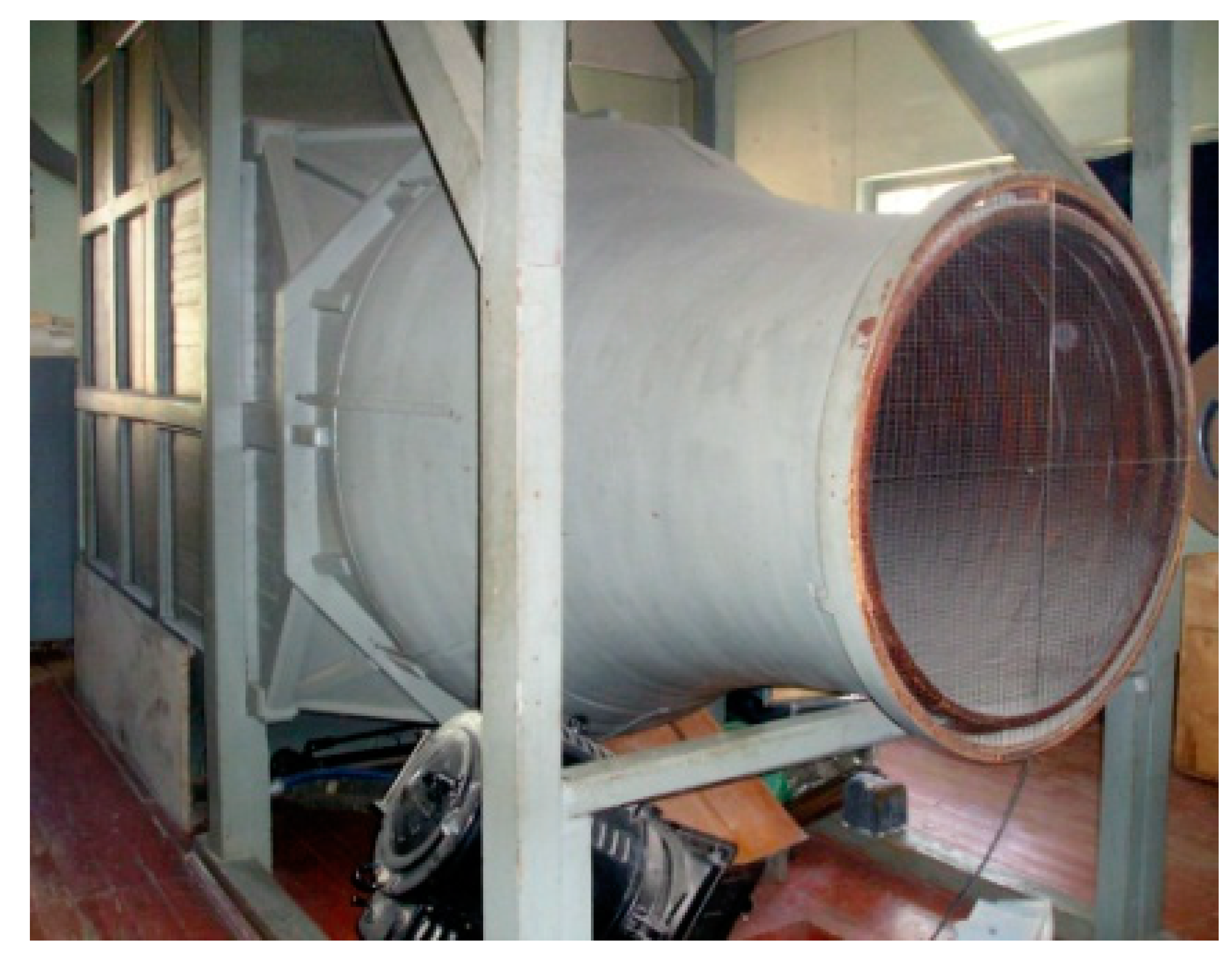
To investigate the different influence of the angle of wind inflow and the height of the duct on the aerodynamic coefficients, experimental aerodynamic research was carried out in the two-circuit aerodynamic tunnel (Figure 2) with the size of the opened working section d × D = 1.0 m × 1.2 m.
Circulation currents and stagnant zones appear around the house, in which, due to the lack of natural ventilation, the accumulation of polluted air can occur. When determining the amount of natural air exchange, when choosing the location of intake and exhaust openings, for calculating the spread of toxic emissions into the atmosphere, as well as for calculating forces in the structural elements of buildings, it is necessary to know the distribution of static pressures on the surface of the building under the influence of wind and the patterns of air movement in the area impact of buildings. An approximate theoretical determination of the distribution of static pressures is possible only on the simplest buildings. Therefore, to determine the pressure distribution on the surface of the building, experimental studies are carried out in a wind tunnel (Figure 3).
The wind tunnel has the following characteristics:
-
The working part is open type; diameter of the working part is 1 m; the length of the working part is 1.2 m.
-
The wind tunnel refers to closed-type pipes with two recirculation channels.
-
The speed mode is subsonic, the maximum air flow speed is 37 m/s.
-
The drive of the wind tunnel is carried out using an axial fan equipped with a direct current electric motor with the possibility of smooth adjustment of the rotation freequancy; power of the electric motor is 31 kW.
-
The source of direct current is a Siemens firm generator.
-
The wind tunnel is equipped with a six-component mechanical weight.
This wind tunnel provides high technological accuracy of aerodynamic measurements. The flow rate coefficient is achieved at the level of 0.99, which is extremely high accuracy. The pipe provides stable air movement at low speeds of 3.5-5.0 m/s, which is especially important when conducting research in the field of building aerodynamics. (A number of wind tunnels for operation in the low speed range is equipped with a separate drive).
A significant advantage of this wind tunnel of this type is the small drive power (31 kW) and the open working part.
The essential advantage of the open working part is that with the correct selection of the shape and size of the diffuser inlet, it allows to minimize the static pressure gradient along the axis of the wind tunnel. This is especially important when measuring the aerodynamic resistance.
At the same time, the total correction for the blocking coefficient is much smaller than in wind tunnels with a closed working part. Free access to research models is also essential, it positively affects the quality and accuracy of measurements and simplifies the conduct of experiments.
The shape of the nozzle is decisive for the quality of research in the wind tunnel, along with the nozzle compression coefficient. From this point of view, the nozzle should be as short as possible. It is very important that the local velocity vector at each point of the flow is parallel to the axis of the working part. Of the many mathematical dependences offered for the calculation of the nozzle geometry, today the preference is given to lemniscate, which is well suited for the calculation of an axisymmetric nozzle. Good results are obtained for nozzles with a length approximately equal to 1/3 of the diameter of the inlet section. The coefficient of compression of the nozzle is defined as the ratio of the area at the entrance to the nozzle and at the exit from it. A high degree of compression contributes to the equalization of the profile of the flow velocities at the exit from the nozzle and the reduction of turbulence.
All the listed advantages of the wind tunnel allow you to successfully solve the following tasks.
1. Research of aerodynamic and dynamic characteristics of objects of civil and general industrial purpose.
During the study of ground buildings and structures (television and communication towers, poles of power transmission lines, high-rise buildings for both residential and industrial purposes, bridges, overpasses, chimneys of thermal power plants and boiler houses, wind power plants) the following tasks are solved:
-
load on the foundation from wind action;
-
wind loads on the facades of buildings and structures;
-
detection of zones of aerodynamic instability of buildings and structures;
-
research on methods of damping vibrations of buildings and structures under wind loads.
When investigating the effectiveness of ventilation systems at the design stage and when carrying out work on sealing buildings, the operation of aeration lights, ventilation shafts, deflectors, the interaction of the jet with the air flow running into them, the aeration of premises and industrial sites is studied.
2. Determination of aerodynamic characteristics of vehicle models and their elements; measurement of stationary and non-stationary pressure distributions on the surface of the model.
During the study of the aerodynamic characteristics of vehicles, the following are determined: aerodynamic resistance; stability and controllability at high speeds; ventilation in the vehicle cabin; the influence of ventilation devices (inflow and exhaust) on the thickness of the boundary layer of the air flow and the frontal resistance coefficient of the vehicle movement.
At the same time, physical studies of the models are also carried out (visualization of the laminar-turbulent transition and air flow around the air stream taking into account various conditions and factors.
The wind tunnel allows for metrological certification of means of measuring the speed and direction of the air flow.
The wind tunnel of the National University "Lviv Polytechnic" provides an opportunity to carry out aerodynamic research in the field of construction and architecture, mechanical engineering and the development of new technologies for the use of wind energy. The open working part of the pipe makes it possible to effectively measure and determine the aerodynamic characteristics of research objects using the model. It is possible to visualize the air flow with the help of smoke and the use of adhesive tapes on the models. In addition, small air flow velocities in the working part of the wind tunnel, which are in the range from 3.5 m/s to 37 m/s, allow conducting studies of the aerodynamics of buildings, as they are considered very important, and in certain cases are decisive for the design of ventilation system of the house and finding the calculated air exchange of the room. The aerodynamics of high-rise buildings has its own specificity, because for them the influence of external climatic factors and the magnitude of gradients of movement of mass and energy flows on the building is extreme in its significance. Research in the wind tunnel makes it possible to choose enclosing structures with the necessary air permeability, to evaluate the impact of the building on the aerodynamic regime of the adjacent territories.
Having in its arsenal various types of devices, with the help of a wind tunnel it is possible to fully provide the entire range of services related to the study of aerodynamic phenomena that occur when flowing around buildings and structures, vehicles, as well as ventilation of certain volumes of premises. Currently, relevant research in the field of low-speed aerodynamics remains:
  • fundamental research of non-stationary and eddy currents of aerodynamic objects;
  • research of aerodynamic characteristics of vehicles as well as buildings and structures of various architectural forms in a wind tunnel;
  • mathematical modeling of the aerodynamics of ventilation of public and industrial facilities;
  • numerical solutions of boundary layer and heat and mass transfer problems;
  • modeling of environmental problems and problems of the spread of harmful substances and noise;
  • determining the aerodynamic characteristics of new configurations of buildings and structures, with an emphasis on assessing the accuracy of numerical methods;
  • establishing the limit of aeromechanical stability of modern rotors and rotor-fuselage structures of wind generators;
solving problems of industrial aerodynamics.
The investigation was carried out at Lviv Polytechnic National University in Ukraine. The building models is shown in Figure 3. This was the exact copy of the building with ventilation and smoke ducts in scale 1:150.
Research was conducted under the following conditions, assumptions and simplifications:
  • height h of ducts in the building: 6 m, 9 m, 10 m, 11.5 m;
  • angles α of wind directions (Figure 1): -900, - 450, 00, +450, +900;
  • the speed of the air flow: 13-20 m/s which corresponds to Re = 2-3 105 (auto-model zone).
This article applies the methods of experiment planning and process optimization in ventilation technology. When planning the experiment, the following main advantages were used:
  • simultaneous change of all process-determining variables, thereby significantly reducing the number of necessary experiments;
  • the optimal choice of experimental conditions, the totality of which ensures obtaining a mathematical model with the desired statistical properties;
  • development of a clear strategy for conducting the experiment, making informed decisions at each successive stage, which makes it possible to formalize a significant part of the work of the experimenter.
When choosing factors, it was taken into account that a factor is an independent measurable variable that at some point in time acquires a certain value, that is, is at a certain level (lower or upper). This means that the planning of a complete two-factor experiment of type 2k, which is the most common in scientific research, was implemented in the article. Such plans require a minimum number of experiments, namely: N = 2k, where N is the number of experiments, k is the number of factors, 2 is the number of levels.
When choosing factors, the following requirements were met:
1. The factor must be controllable, that is, under the control of the experimenter.
2. The factor must satisfy the specified high accuracy of measurements, because this affects the final result.
3. Factors must be unambiguous, because it is difficult to manage factors that have functions of other factors.
4. Factors must be compatible and independent.
Similarly, the relevant requirements for the optimization parameter were met:
1. The optimization parameter must be expressed unambiguously, i.e. by a single number, and also correspond to unambiguity in the statistical sense (each factor corresponds to a single value of the optimization parameter with a certain accuracy, but the converse statement is incorrect).2. To successfully achieve the goal of the research, it is necessary that the optimization parameter really evaluates the effectiveness of the system functioning in the pre-selected content. This requirement is the main one that determines the correctness of the problem formulation.
3. The next requirement is universality, or completeness. These concepts mean the ability of a parameter to comprehensively characterize an object.
4. It is necessary that the optimization parameter has a physical meaning, is simple and relatively easy to calculate.
When processing the results, a non-linear mathematical model (polynomial of the second degree) was adopted. To determine the aerodynamic coefficient k the two-factor experiment was planned considering angle α of air inflow (wind direction) and height h of the smoke and ventilation duct. The matrix of a two-factor experiment with the effect of the interaction of the determining factors on three levels is presented in Table 1.
In the planning matrix (Table 1), x0 is a fictitious dimensionless factor that is only at the upper level (+) ensuring the property of symmetry [37]. Other ones x1 and x2 are dimensionless factors that are at the lower (-) and upper (+) levels, because this is planning of a full factorial experiment of 2k type [37]. It should be noted that the experiment planning matrix (Table 1) satisfies the following properties:
1. The property of symmetry with respect to the center of the experiment, that is, the algebraic sum of the elements of the column vector of each factor is zero.
2. The property of normalization, that is, the sum of the squares of the elements of each column is equal to the number of experiments.
3. The orthogonality property of the planning matrix, i.e. the sum of the term-wise products of any two vectors is zero.
4. The property of rotatability, that is, the points in the planning matrix are selected so that the accuracy of predicting the values of the optimization parameter is the same at the same distances from the center of the experiment and does not depend on the search direction.

3. Results

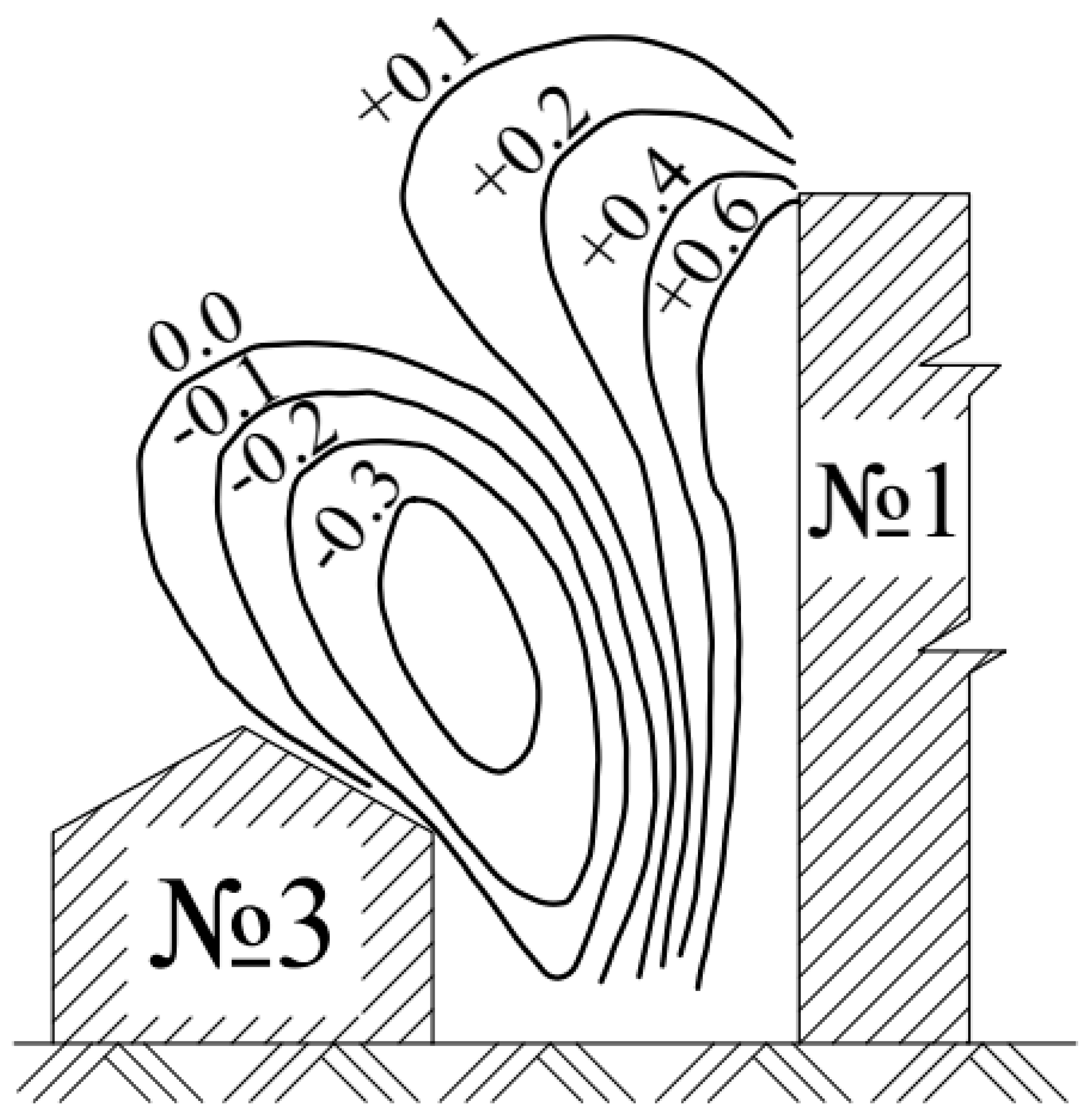
The results of the experimental studies on aerodynamic coefficients were developed as graphs. In Figure 4 it is shown the field of aerodynamic coefficients in the cross-section I-I (Figure 1) of the windward area of the high-rise building No 1 at the angle of the air inflow α = 00. A vortex formation above house No 3 is visible, which contributes to the correct operation of smoke and ventilation ducts. Studies of the leeward area of the building carried out in the same cross-section I-I showed that steady rarefaction of approximately the same magnitude takes place.
The aerodynamic coefficients in dependence on the wind direction (angle α) and the height h of the smoke and ventilation ducts for double-storied building are displayed in Figure 5. Graphs have been approximated by dependence:
k = 0.076 + 0.021 h + 0.0035 α + 6 h 17 10 6 α 2
Analysis of the data in Figure 5 shows that at α = 00 for all heights of ducts building have a positive aerodynamic coefficient. In this context, it is necessary to increase the height of the duct, to build them up. At the angle of air α = +450 all ducts are also in the high pressure zone. To ensure rarefaction in the ducts deflectors were modeled, however this solution did not provide the expected effect. Therefore, there was a need to increase the height of the ducts to ensure a slight rarefaction in them. This value should be determined individually for each duct by iterations.
In the next step the regression equation to calculate the aerodynamic coefficients was obtained as follows:
k = 0.265 + 0.318 · x 1 0.083 · x 2 0.0025 · x 12
The regression analysis proved that the coefficient, which equals -0.0025 can be neglected, that is, the effect of the interaction of factors (wind direction and ducts height) is not observed, so the equation of regression is as follows:
k = 0.265 + 0.318 · x 1 0.083 · x 2
.
An increase of the angle α (wind direction) results in an increase of the aerodynamic coefficient, and an increase of the height of the ventilation and smoke ducts – to its decrease. Whereby, the direction of the wind, reveals a greater influence than the height of the ducts.

4. Conclusions

The discussed issue shows the problem of proper design of small areas with buildings of different stories. To ensure citizen safety and correct work of ventilation and smoke ducts preliminary aerodynamic studies are necessary. Graphs and empirical equations for the determination of aerodynamic coefficients of buildings depending on the angle of air inflow and duct height have been received. The results were testified experimentally.
The maximum value of the aerodynamic coefficients for building is observed at the angle of air α = +450. It means that all ducts are in the high-pressure zone and the improvement of pressure conditions is necessary. The use of deflectors on duct gives no result, that to provide rarefaction the height of the duct must be increased.
Zones with optimal placement of the exhaust ventilation and the smoke ducts have been determined.

Author Contributions

Conceptualization, O.V.; methodology, N.S.; software, O.S.; validation, I.S., O.D. and M.K.; formal analysis, O.S.; investigation, O.D.; resources, I.S.; writing—original draft preparation, O.V. and E.D.; writing—review and editing, N.S. and E.D; visualization, M.K.; supervision, O.V.; project administration, N.S.; funding acquisition, O.V. All authors have read and agreed to the published version of the manuscript.

Funding

This research received no external funding.

Acknowledgments

The authors would like to express gratitude for the invitation to submit articles to the Urban Science journal without any charges. It is sincerely appreciated.

Conflicts of Interest

The authors declare no conflict of interest.

References

  1. Kapalo, P.; Klymenko, H.; Zhelykh, V.; Adamski, M. Investigation of Indoor Air Quality in the Selected Ukraine Classroom - Case Study. Lecture Notes in Civil Engineering, 2020; 47, 168–173. [Google Scholar] [CrossRef]
  2. Kapalo, P.; Sulewska, M.; Adamski, M. Examining the Interdependence of the various parameters of indoor air. Proceedings of EcoComfort, 2021; 100, 150–157. [Google Scholar] [CrossRef]
  3. Kapalo, P.; Vilčeková, S.; Mečiarová, L.; Domnita, F.; Adamski, M. Influence of indoor climate on employees in office buildings - A case study. Sustainability 2020, Volume 12, No. 14, Paper no. 5569. [CrossRef]
  4. Poorova, Z.; Alhosni, M.S.; Kapalo, P.; Vranayova, Z. Change of temperature in the room with the living wall. IOP Conference Series: Materials Science and Engineering 2019, Volume 603, No. 5, Paper no. 052063.
  5. Poorova, Z.; Vranayova, Z. Humidity, air temperature, CO2 and well-being of people with and without green wall. Proceedings of EcoComfort 2020, Lecture Notes in Civil Engineering 2021, Volume 100, pp. 336–346. [CrossRef]
  6. Logue, J.M.; Sherman, M.H.; Walker, I.S.; Singer, B.C. Energy impacts of envelope tightening and mechanical ventilation for the U.S. residential sector. Energy Build. 2013, Volume 65, pp. 281–291. [CrossRef]
  7. Voznyak, O.; Spodyniuk, N.; Sukholova, I.; Dovbush, O.; Kasynets, M.; Datsko, O. Diagnosis of damage to the ventilation system. Diagnostyka 2021, Volume 22, No. 3, pp. 91 – 99. [CrossRef]
  8. Voznyak, O.; Spodyniuk, N.; Sukholova, I.; Savchenko, O.; Kasynets, M.; Datsko, O. Diagnosis of three types damages to the ventilation system. Diagnostyka 2022, 23, No. 1. 2022102. [Google Scholar] [CrossRef]
  9. Amanowicz, Ł.; Ratajczak, K.; Dudkiewicz, E. Recent advancements in ventilation systems used to decrease energy consumption in buildings - literature review. Energies 2023, Volume 16, No. 4, art. 1853, pp. 1-39. [CrossRef]
  10. Spodyniuk, N.; Zhelykh, V.; Dzeryn, O. Combined Heating Systems of Premises for Breeding of Young Pigs and Poultry. FME Transactions 2018, Volume 46, No. 4, pp. 651-657. [CrossRef]
  11. Kusnir, M.; Vranay, F.; Kosicanova, D.; Vranayova, Z.; Stefanco, M. Synergic application of renewable energy sources in reducing energy load of buildings. International Multidisciplinary Scientific GeoConference Surveying Geology and Mining Ecology Management 2014, Volume 1, No. 4, pp. 489–496.
  12. Lis, P.; Lis, A.; Janik, M. Aspects of the analytical heat consumption monitoring in local buildings' population. Rynek Energii 2012; Volume 102, No. 5, pp. 67–75.
  13. Vranay, F.; Vranayova, Z. Influence of heat source choice on building energy certification process and CO2 emissions. Proceedings of CEE 2019 2020, Volume 47, pp. 541–548. [CrossRef]
  14. Baborska-Narożny, M.; Kostka, M.K. Seasonal air quality in bedrooms with natural, mechanical or hybrid ventilation systems and varied window opening behavior-field measurement results. Energies 2022, Volume 15, No. 24, art. 9328, pp. 1-17. [CrossRef]
  15. Heim, D.; Miszczuk, A. Modelling building infiltration using the airflow network model approach calibrated by airtightness test results and leak detection. Build. Serv. Eng. Res. Technol. 2020. [CrossRef]
  16. Yi, Q.; Wang, X.; Zhang, G.; Janke, H.; Li, D.; Amon, T. Assessing effects of wind speed and wind direction on discharge coefficient of sidewall opening in a dairy building model—A numerical study. Comput. Electron. Agric. 2019, Volume 162, pp. 235–245. [CrossRef]
  17. Du, Y.; Zhu, Zh. Research on the Form of Energy-saving Building under the Influence of Natural Ventilation Technology. Journal of Physics Conference Series 2023, Volume 2468, pp. 012163.
  18. Bramiana, C.N.; Entrop, A.G.; Halman, J.I.M. Relationships between Building Characteristics and Airtightness of Dutch Dwellings. Energy Procedia 2016, Volume 96, pp. 580-591. [CrossRef]
  19. Cardoso, V.E.M.; Pereira, P.F.; Ramos, N.M.M.; Almeida, R.M.S.F. The impacts of air leakage paths and airtightness levels on air change rates. Buildings 2020, Volume 10, No. 3. [CrossRef]
  20. Felimban, A.; Prieto, A.; Knaack, U.; Klein, T.; Qaffas, Y. Residential Buildings in Jeddah, Saudi Arabia. Buildings 2019. [CrossRef]
  21. Hu, G.; Hassanli, S.; Kwok, K.C. ; Tse; K.-T. Wind-induced responses of a tall building with a double-skin facade system. J. Wind. Eng. Ind. Aerodyn. 2017, Volume 168, pp. 91–100. [CrossRef]
  22. Jokisalo, J.; Kurnitski, J.; Korpi, M.; Kalamees, T.; Vinha, J. Building leakage, infiltration, and energy performance analyses for Finnish detached houses. Build. Environ. 2009. [CrossRef]
  23. Wen, Y.; Guo, Q.; Xiao, P. ; Ming; T. The Impact of Opening Sizing on the Airflow Distribution of Double skin Facade. Procedia Eng. 2017, Volume 205, pp. 4111–4116. [CrossRef]
  24. Younes, C.; Shdid, C.A.; Bitsuamlak, G. Air infiltration through building envelopes: A review. J. Build. Phys. 2012, Volume 35, No. 590, pp. 267–302. [CrossRef]
  25. Zhou, J.; Hu, Y.; Zhang, G. Unsteady characteristics of natural wind and its influence on indoor environment. Sci. Technol. Rev. 2012, Volume 30, pp. 62–68.
  26. Asami, M.; Kimura, A.; Oka, H. Improvement of a Diagnostic Urban Wind Model for Flow Fields around a Single Rectangular Obstacle in Micrometeorology Simulation. Fluids 2021, Volume 6, No. 7, 254. [CrossRef]
  27. 27. Gorobets,V.; Trokhaniak, V.; Masiuk, M.; Spodyniuk, N.; Blesnyuk, O.; Marchishina, Ye. CFD modeling of aerodynamic flow in a wind turbine with vertical rotational axis and wind flow concentrator. INMATEH – Agricultural Engineering 2021, Volume 64, pp. 159 - 166. [CrossRef]
  28. Khmil, R.; Tytarenko, R.; Blikharskyy, Y.; Vegera, P. The Probabilistic Calculation Model of RC Beams, Strengthened by RC Jacket. Lecture Notes in Civil Engineering 2021, 100 LNCE, pp. 182 – 191. [CrossRef]
  29. Klymchuk, A.; Lozhechnikov, V.; Mykhailenko, V.; Lozhechnikova, N. Improved mathematical model of fluid level dynamics in a drum-type steam generator as a controlled object. Journal of Automation and Information Sciences 2019, Volume 51, No. 5, pp. 65–74. [CrossRef]
  30. Georgakis, G.; Santamouris, M. Experimental investigation of air flow and temperature distribution in deep urban canyons for natural ventilation purposes. Energy Build. 2006, Volume 38, pp. 367–376.
  31. Mortensen, L.H.; Bergsoe, N.C. Air tightness measurements in older Danish single-family houses, 2017. [CrossRef]
  32. Nasrollahi, N.; Ghobadi, P. Field measurement and numerical investigation of natural cross-ventilation in high-rise buildings. Thermal comfort analysis. Appl. Therm. Eng. 2022, Volume 211, 118500. [CrossRef]
  33. Mjabber, E.K.E.; Khamlichi, A.; Hajjaji, A.E. Nonlinear control of wind turbine in above rated wind speed region. Pollack Periodica 2022, Volume 17, No. 1, pp. 72 – 77.
  34. Bytčanková, L.; Rumann, J.; Dušička, P. Distribution of flow velocity in a shaft intake structure. Pollack Periodica 2022, Volume 17, No. 1, pp. 83 – 87. [CrossRef]
  35. Hnativ, R.; Verbovskiy, O. Distribution of local velocities in a circular pipe with accelerating fluid flow. Eastern-European Journal of Enterprise Technologies 2019, Volume 2, No. 7-98, pp. 58–63. [CrossRef]
  36. Snitynskyi, V.; Khirivskyi, P.; Hnativ, I.; Yakhno, O.; Machuga, O.; Hnativ, R. Visualization of river water flow in hydrodynamically active areas under different flow regimes. Journal of Ecological Engineering 2021, Volume 22, No. 9, pp. 129–135. [CrossRef]
  37. Voznyak, O.; Spodyniuk, N.; Savchenko, O.; Dovbush, O.; Kasynets, M.; Datsko, O. Analysis of air jets velocity attenuation at special initial conditions. Diagnostyka 2022, Volume 23, No. 3, 2022308. [CrossRef]
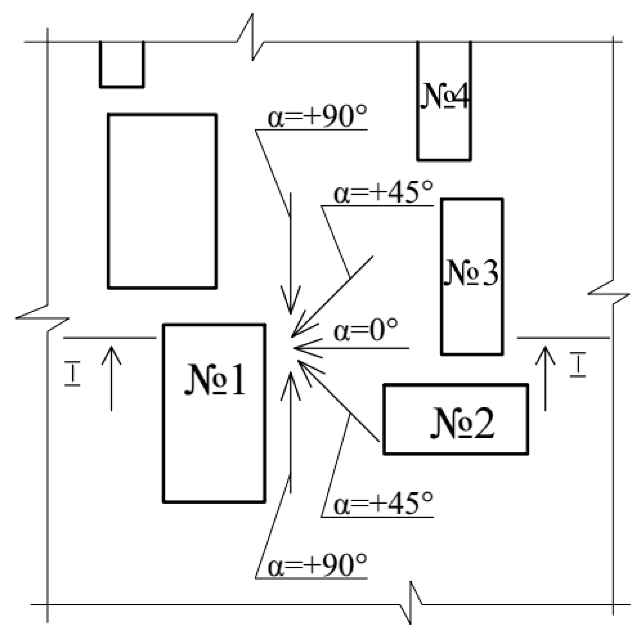
Figure 1. Scheme of the model: No 1 – 9-storied building; No 2, No 3 and No 4 – double-storied residential buildings; α – the angle of the air inflow (wind) direction.
Preprints 77920 g001
Figure 2. Working part of a wind tunnel.
Preprints 77920 g002
Figure 3. Buildings models in a wind tunnel.
Preprints 77920 g003
Figure 4. The field of aerodynamic coefficients in the section I-I at α = 00
Preprints 77920 g004
Figure 5. Dependence of aerodynamic coefficients on wind direction (angle α) and height h of smoke and ventilation ducts for double-storied building.
Preprints 77920 g005
Table 1. Planning matrix of a two-factor experiment.
No x0 x1 x2 x1*x2 k
1 + - - + -0.46
2 + 0 - 0 +0.07
3 + + - - +0.18
4 + - 0 0 -0.49
5 + 0 0 0 +0.11
6 + + 0 0 +0.12
7 + - + - -0.62
8 + 0 + 0 +0.18
9 + + + + +0.01
Disclaimer/Publisher’s Note: The statements, opinions and data contained in all publications are solely those of the individual author(s) and contributor(s) and not of MDPI and/or the editor(s). MDPI and/or the editor(s) disclaim responsibility for any injury to people or property resulting from any ideas, methods, instructions or products referred to in the content.
Copyright: This open access article is published under a Creative Commons CC BY 4.0 license, which permit the free download, distribution, and reuse, provided that the author and preprint are cited in any reuse.
Prerpints.org logo

Preprints.org is a free preprint server supported by MDPI in Basel, Switzerland.

Subscribe

© 2024 MDPI (Basel, Switzerland) unless otherwise stated