1. Introduction
The most widely applied and researched passive balancing devices for vibration suppression of eccentric rotors are the Automatic Ball Balancers (ABBs) at present. The main components are composed of a circular orbit mechanism mounted perpendicular to the spindle of the rotor and revolving with the rotor, and several balls that can freely move inside the track. In 1975, Sharp [
1] established an ideally mounted two-ball balancer of a plane rotor system from the 2D viewpoint and derived the equations of motion to analyze stability. Lee [
2] in 1996, Green [
3] in 2006 and Lu [
4] in 2009, etc., have explored the problems and phenomena of ABBs suppressing vibration in the model without assembly deviations.
However, when ABBs are mounted with an eccentric rotor system, assembly deviations can include the deviations of the vertical and horizontal position of the ABB's centroid and the centroid of eccentric rotor as well as the deflection of the mounted angle. Regarding the discussions of vertical position deviation, Kim [
5] in 2005 and Chao [
6] in 2007 investigated the dynamic behavior of the system when the ABB is mounted at a small distance below the centroid of plane eccentric rotor by theoretically and experimentally respectively. Numerical analysis and experimental results show that the system can still be balanced in an approximate ideal mounted (ABB is coplanar with the plane rotor), and the balls are positioned at appropriate angular positions to effectively reduce the radial residual vibration in steady-state and the tilting angle during rotor balancing [
5], where the radial amplitude can be almost completely suppressed, yet the tilting angle during balancing exists a finite amount [
6]. Furthermore, regarding the discussions of horizontal position deviation, Bykov in 2014 [
7] and 2018 [
8] proposed the axis of symmetry of ABB does not coincide with the symmetry axis of the rotor which the ABB and the plane rotor are coplanar, the system has two types of unbalanced steady-state modes when the working speed is greater than the critical speed of the system. As for the deflection of the mounted angle, Huang [
9] in 2022 among the vibration suppression system established an angular deviation model between the plane of ABB's track and the plane of the eccentric rotor. The angular positions of the balls and their restriction conditions are analyzed and propose the examination principle of the ABB is skew-mounted, and the conditions for perfect balance of the ideal and skew-mounted ABB.
Generally, the dynamic equilibrium equations of the vibration suppression rotor system are derived that the mathematical model of the system is established first. Then the kinetic energy, potential energy and energy dissipation functions of the system are listed one by one. Next the Euler-Lagrange method is used to obtain the governing equations, the dynamic equilibrium equations of the system are obtained under the conditions that their differential terms are zero. Reference [1-6, 9] as well as recent works by Jung [
10] in 2018 and Rezaee [
11], Filimonikhin [
12] and Bykov [
13] in 2019 are all based on the Lagrange equation to derive the equations of motion of the system.
In order to make the study of the angular deflection of ABB more complete, this paper deduces the dynamic equilibrium equations of the vibration suppression system in the steady-state by 3D dynamics method to verify the derivations of [
9] with each other. Consistent results are obtained. Due to the mounted angular deflection will cause the plane which circular orbit of the ABB cannot be completely fitted to the plane of the eccentric rotor. In the model of the steady-state vibration system with angular deviation, the spatial dynamics method can find the geometric phenomenon and relationships from the derived equations. Regardless of whether assembly deviations of ABBs, the dynamic balance position of any ball must be satisfied the necessary spatial geometry characteristic.
2. System Model
The model is based on angular deviation of skew-mounted.
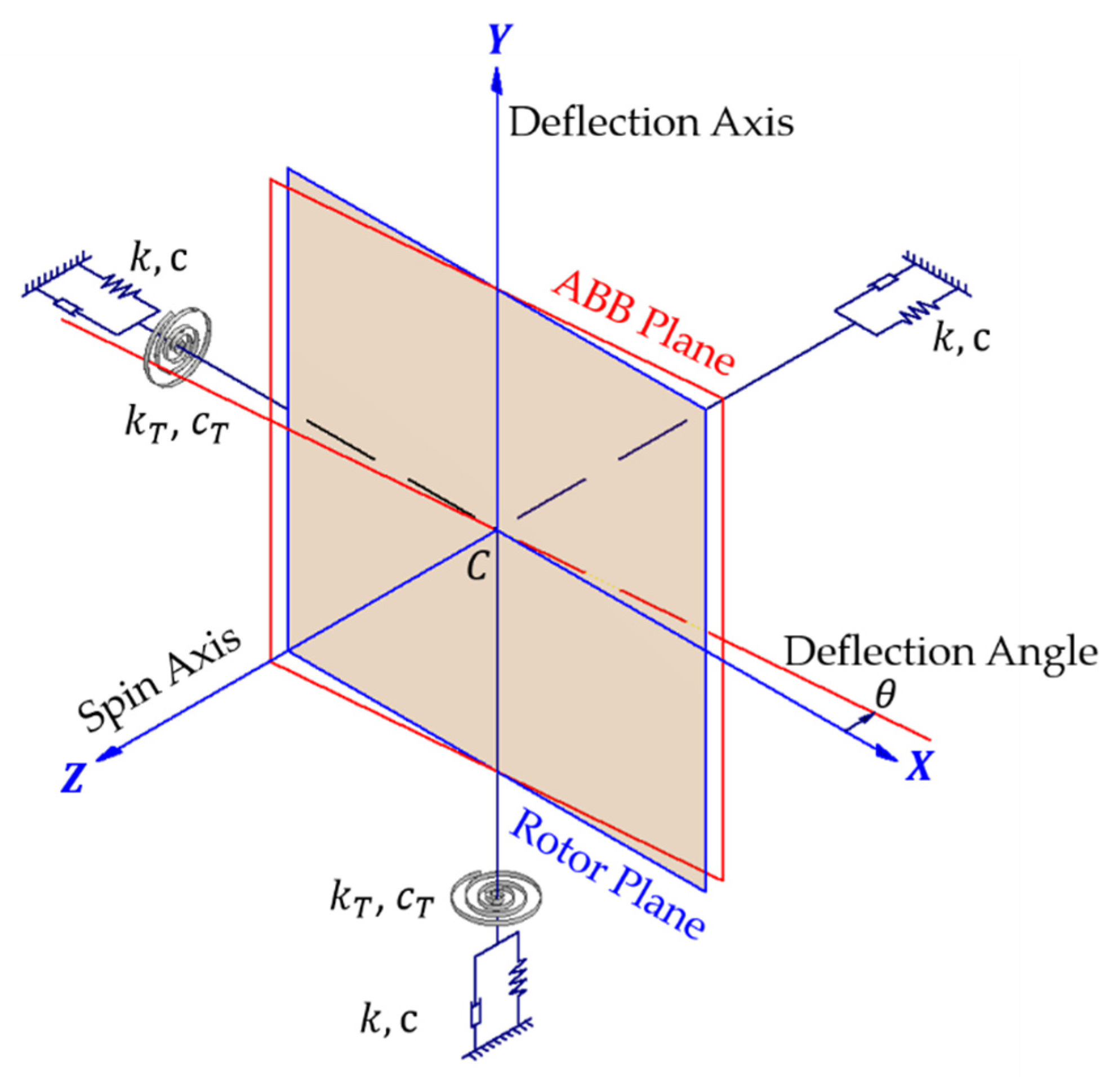
Figure 1 shows the skew-mounted model of the angular deviation between the plane of the balls moving in ABB’s track and the rotor plane when the spindle speed is zero. The plane formed by the blue frame in
Figure 1 is the plane where the eccentric rotor is located and
is its centroid, while the red frame represents the orbit plane of ABB. The ABB plane does not coincide with the rotor plane that is perpendicular to the spin axis of the system at rest. The deflection angle as shown is
. Suppose skew-mounted ABB only the angle deflection of track plane without the position deviation of the centroid, then the ABB's centroid coincides with the centroid
of the planar rotor at static. The intersection line of two planes should pass through the centroid
. As shown, the coordinate system
is a space-fixed reference frame of the planar rotor, with the origin defined at the position of its centroid. The intersection line of two planes lies on the
-axis.
When the system operates stable, due to the deflection of the orbit plane of ABB and the rotor plane, although the centrifugal forces acting on their respective planes both pass through the rotation axis, the intersection of each with the rotation axis is not necessarily the same. Which may generate torques for the whole assembly system. In this paper, the spin axis (-axis) of the system is defined as the roll axis in a tri-axial system, and the pitch and yaw angles of the system should be considered for the phenomenon of torque. Therefore, in addition to the tri-axial isotropic linear spring and viscous damper , the elastic supports of the system should also consider the roles of the torsion spring and torsion damper in the other two axes except for the spin axis, as shown. The dynamic balance of this 3D model will be analyzed using spatial dynamics.
3. 3D Dynamic Deduction
3.1. Coordinate System
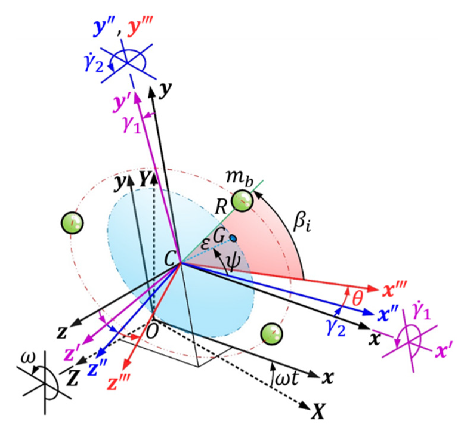
In order to understand and analyze the spatial position, attitude, and motion mechanism of the rotor system equipped with skew-mounted ABB, the coordinate systems of the ABB mechanism, eccentric rotor, and support device are constructed as shown in
Figure 2. The rectangular coordinate
is a space-fixed reference frame of the planar rotor, the origin
is defined at the centroid position of the eccentric rotor when the spindle speed is zero and the system is stationary and the support springs are not deformed. The
-axis is the deflection axis where mounting deviation occurs (refer to
Figure 1). Moreover, the rotating reference frame
is defined with the origin located at point
and
axis of the
frame. The
coordinate system rotates around the spindle
-axis of the system with a constant angular velocity
. The reference frame can be transformed to the rotating frame by a rotation matrix
.
When the deformations of the support springs, the position of the offset centroid set the coordinate system, which is always parallel and same direction to each axis of except for the different origin position. Then rotating the pitch angle around the -axis which is in coordinate system, and the rotating coordinate system where be obtained. Next rotating the yaw angle around the -axis of coordinate system to obtain the rotating coordinate system where and the -axis passes through the rotor centroid and is perpendicular to the plane of the rotor ( plane). Converting to and by rotation matrix and in sequence. The mass center of eccentric rotor with mass is located on the plane of rotor and the eccentricity between and its centroid is . The angle between and the -axis is .
The body-fixed coordinate system
follows the rotor system in 3D space such that the
-axis is also the deflection axis of skew-mounted ABB. Rotating the deflection angle
around the
-axis of the
to obtain the coordinate system
of the orbit plane, where
. It can convert
to
by rotation matrix
. The radius of the circular orbit of the ABB is
, there are
balls moving in the orbit and the mass of each ball is
. The angular position of the
-th ball from the
-axis is denoted
. The rotation matrixes between the coordinates as
3.2. Spatial forces of dynamic balance
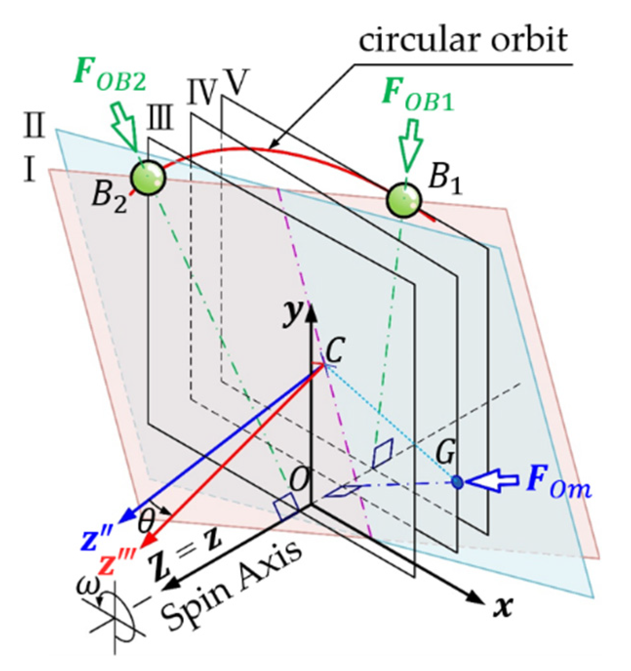
When the system is in dynamic balance, each particle of the system always maintains a fixed relative position to the observer of the rotating coordinate system attached to the spindle with the same angular velocity. The centripetal force required to maintain the constant angular velocity is provided by the constraint force generated by the deformation of the suspension or support device of the system. The plane of ABB's track of the rotor system with a skew-mounted ABB does not coincide with the plane of the rotor, as shown in
Figure 3, Plane Ⅰand Plane Ⅱ. When the dynamic system is steadily balanced, the balls and the rotor centroid revolve around the spin axis, but each of them is on a different plane perpendicular to the spin axis.
and
in
Figure 3 are any two balls in the same circular orbit, but belong to two parallel planes Ⅲ and Ⅴ perpendicular to the spin axis; the other parallel plane Ⅳ is the plane of mass center
of eccentric rotor. From this corollary, n balls and the mass center of eccentric rotor, the dynamic equilibrium analysis of (n+1) planes perpendicular to the spin axis and parallel to each other needs to be explored to obtain the dynamic equilibrium equations.
3.3. Dynamic Equilibrium Equations
3.3.1. Tri-axial Force Balance of Frame
The spindle constant-speed of a rotor system equipped with a skew-mounted ABB is ω. In the rotating reference frame
, the angular velocity of the system is denoted as
, and the position of the offset centroid
after the deformations of the support springs can be expressed as the vector
. The system is a dynamic balance, the equilibrium position of the rotor centroid
is expressed as the vector
As well,
,
, and
are the equilibrium pitch angle, equilibrium yaw angle, and
balls' equilibrium angular positions, respectively. From the definition of coordinate systems (
Figure 2), the position vector of mass center
of the rotor in
as
The equilibrium position vector of mass center of the
-th ball in
is
, the reverse transformation is in
as
, where
Therefore, the equilibrium position vectors (Equations (3) and (5)) are inverted to the rotating reference frame
, which is
The action forces of the steadily balanced system should include the centripetal force
and
acting on the system when the rotor mass center and
balls revolve around the spin axis, as well as the supporting spring force
and the supporting damping force
.
and
are all on parallel planes perpendicular to the spin axis (ref.
Figure 3). By 3D dynamics [
14], the above forces in
frame can be obtained from the following equations respectively.
Through tri-axial force balance of the rotating reference frame
,
, can list three dynamic equilibrium equations.
3.3.2. Moment Balance Around the -Axis of the Coordinate System
The
and the
are two parallel coordinate systems. In the coordinate system
, the angular velocity
around the
-axis, the centripetal forces
and
) of the rotor mass center and the balls are the same as those in
respectively.
,
(Equation (8)), and
(Equation (9)). The equilibrium position vector of the mass center of the rotor and the
-th ball in
is
and
. To inverse transformation of
and
(Equations (3) and (5)) or to translation of
and
(Equations (6) and (7)) can be obtained as
The absolute angular velocity
of the principal axis of inertia of the eccentric rotor in
can transform by
, and rotor angular momentum
can be obtained from
and the principal moment of inertia tensor
. The torque due to the angular momentum of the eccentric rotor is expressed in the cross-product term
, where
The support reaction moment of the torsion spring to the
-axis in dynamic balance is
. Therefore, 3D spatial moment balance on the
-axis in the coordinate system
is expressed as
The moment equilibrium equation of the system for the
-axis in
can be listed
3.3.3. Moment Balance Around the -Axis of the Coordinate System
and
in
are transformed to
by the rotation matrix
, describe as follows respectively
The equilibrium position vector of the mass center of the rotor and the
-th ball in
is
and
. To inverse transformation of
and
(Equations (3) and (5)) or to transform of
and
(Equations (13) and (14)) can be obtained.
Similarly, the support reaction moment of the torsion spring on the
-axis is
, and 3D spatial moment balance on the
-axis in the coordinate system
is expressed as
The moment equilibrium equation of the system around the
-axis in
can be written
3.3.4. Moment Balance Around the Central Axis Perpendicular to the Orbit Plane
The equilibrium position and the centripetal force vector of the mass center of the
-th ball in
is
(Equation (4)) and
.
can be converted by the
(Equation (20)), written as
When the system is dynamic balanced, the sum of moments in 3D for the central axis (
-axis) perpendicular to the orbit plane is zero. Thus, the dynamic equilibrium equation of the
-th ball around the
-axis of the orbit plane can be obtained.
Comprehensive the above dynamic equilibrium equations (Equations (12), (18), (24) and (27)) from the 3D dynamics are compared with the equations derived from the Euler-Lagrange method [
9] (are listed in
Appendix), which be verified each other to obtain exactly the same results. But the 3D dynamics inference, the analysis of the spatial configurations can better describe and understand the spatial positioning of the balls equilibrium during vibration suppression.
3.4. Positioning Characteristic of Balls Equilibrium
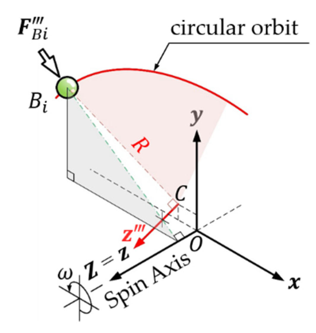
The 3D dynamics show that if the centripetal force of the ball can decompose the component force in the tangential direction of the circular orbit, the ball will move continually along the orbit. Equation (26) implies that when the balls are balance positioning, the torque exerted by the centripetal force of each ball against the
-axis perpendicular to the orbital plane is zero. It means that
has no component force in the tangential direction of the orbit and must pass through the
-axis, as shown in
Figure 4. As well the system is in dynamic balance, the balls revolve around the spin axis (
-axis) of the system with their respective stable and balanced radius at constant angular velocity
. At this time,
is also on the perpendicular line of the
-axis from the mass center of the ball to the spin axis. In other words, when the system is dynamic balance, the centripetal force acting on each ball must be perpendicular to the spin axis and pass through the central axis of the circular orbit of the balls.
The aforementioned inferences reveal that the balls should have the spatial positioning characteristic for dynamic balance. Furthermore, Equation (12.3) express that the dynamic equilibrium displacement of the rotor centroid is zero. It shows that all forces acting on the system are on parallel planes perpendicular to the () axis during dynamic balance, so unforce in the rotation axis. This means that while the balls in the skew-mounted orbit may temporarily cause vibrations at the -axis during the transient period of the system, but once the steady-state balance and the balls are completely positioned, the vibration of the -axis will eventually be attenuated to zero regardless of whether the system achieves a complete balance of vibration suppression.
4. Verification of Spatial Geometric Characteristic
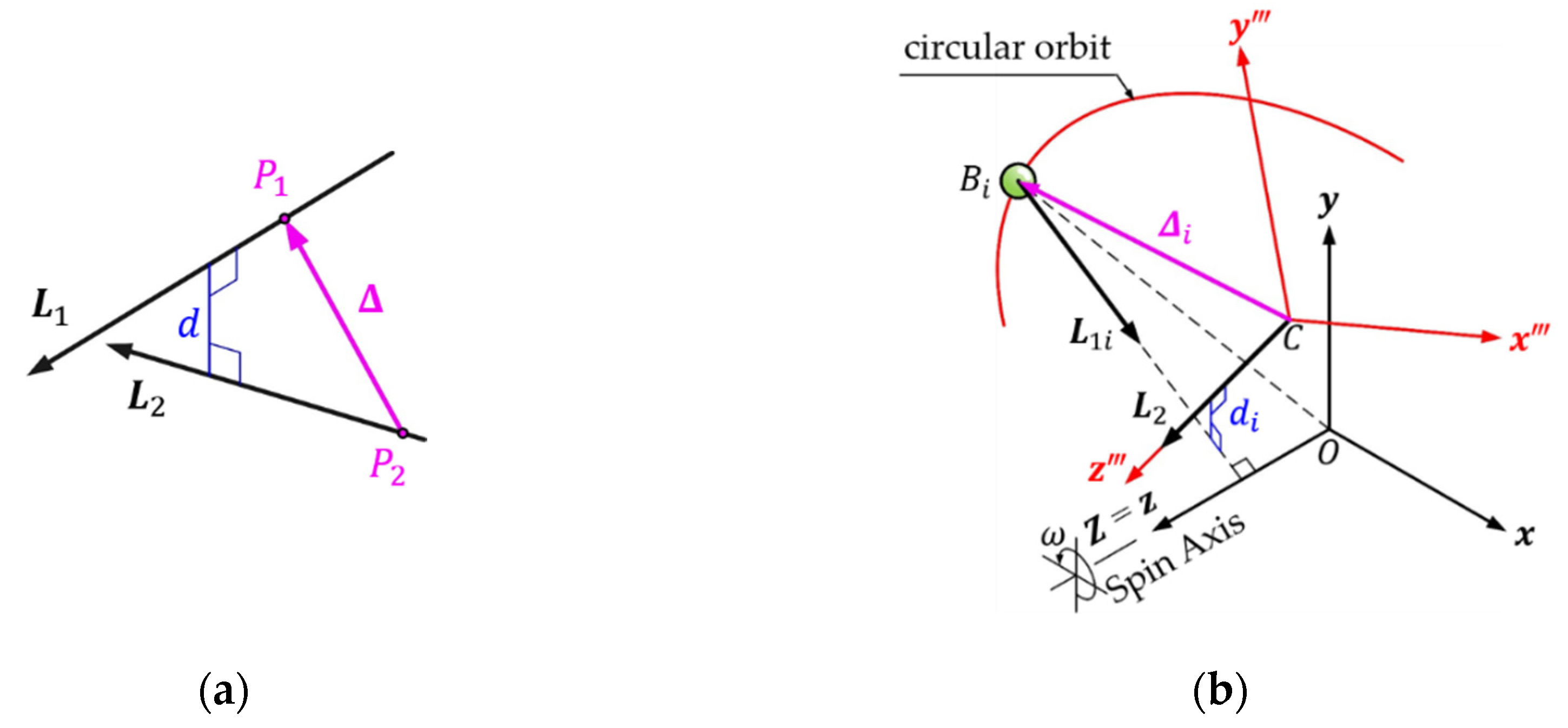
In
Section 3.4, the positioning characteristic of balls in the dynamic balance is stated. For the sake of rigor, the geometric relationships of the space vectors assist to examine and verify. As shown in
Figure 5(a), any two vectors
and
in space, where
and
are arbitrary points on the
and
vectors, respectively, and the displacement of the point
relative to point
is vector
. When the shortest distance
between
and
is zero, which means that vector
and vector
intersect in 3D space, where
Analytic geometry in space applied to the vibration suppression system of eccentric rotor equipped with skew-mounted ABB, the
system synchronized with the spin axis is selected as the reference coordinate system, as shown in
Figure 5(b). The perpendicular line from the
-th ball to the spin
-axis (
) is described as the space vector
, and the unit vector of the central
-axis of the circular orbit is represented by the space vector
. Since the position of the
-th ball and the orbit center
are the points on the
and
vectors, respectively, the relative displacement of the two points is expressed as vector
. In the
system,
can be obtained from
(Equation (7)) and the unit vector
of the
-axis;
and
are obtained by the reverse transformation of the unit vectors
and
(Equation (4)) of the
axis, respectively.
,
and
are expressed as
Substitute Equations (29)–(31) into Equation (28), the shortest distance between
and
is
Because the orbit plane and the eccentric rotor plane are skew-mounted, the orbit center axis is neither collinear nor parallel to the spin axis of the system,
, calculate
to get
Compare the above form with the dynamic equilibrium equation ( Equation (27) ). Since the ball mass and the system angular velocity are both not zero when the system is dynamic balance, we can get Equation (33) equal to zero, that is, . Further prove that Equation (32) to zero, that is, . It means any ball of the orbit after vibration suppression to balance positioning, the radius vector of the position to its stable spin axis intersects with the central axis perpendicular to the orbit plane. In other words, this proves that the steady-state equilibrium position of each ball in the orbit must satisfy the spatial geometric relationship of the perpendicular line from the ball to the spin axis of the vibration suppression system intersects with the central axis of the orbit plane.
5. Conclusions and Future Work
In this paper, the system model is based on the system of an eccentric rotor equipped with skew-mounted ABB to be analyzed via 3D dynamics. The independent variables of the system include the centroid position of the rotor, the pitch angle and the yaw angle of the rotor, as well the angular positions of the balls in the orbit, totaling independent variables. Through the conversion of space coordinates, describe the positions and attitudes of the system in space, and establish independent simultaneous dynamic equilibrium equations.
- (i)
From the tri-axial force balance of the rotating reference frame , three dynamic equilibrium equations of the three independent variables of the centroid position of the rotor are obtained. (Equation (12)).
- (ii)
Based on the moment balance around the -axis of the coordinate system to obtain one dynamic equilibrium equation in the rotational direction of the pitch angle of the system. (Equation (18)).
- (iii)
Based on the moment balance around the -axis of the coordinate system to obtain one dynamic equilibrium equation in the rotational direction of the yaw angle of the system. (Equation (24))
- (iv)
For the moment balance around the central axis perpendicular to the orbit plane of the balls, dynamic equilibrium equations of the angular position of each ball in balance positioning are listed. (Equation (27))
The results verify one another as being completely consistent with the dynamic equilibrium equations derived from the Euler-Lagrange equation [
9]. Among them, when analyzing the dynamic balance of the
-axis in (i), Equation (12.3) can be seen that the dynamic equilibrium displacement of the rotor centroid in the
-direction is zero. All forces acting on the system are on parallel planes perpendicular to the rotating spindle during dynamic balance, so the balls in the skew-mounted orbit will temporarily cause vibrations at the
-axis during the transient period of the system, but once the steady-state balance and the balls are completely positioned, the vibration of the
-axis will eventually be attenuated to zero regardless of whether the system achieves a complete balance of vibration suppression. What is particularly important through 3D dynamics, the dynamic equilibrium equations of ball positioning analyzed in (ⅳ) can deduce the positioning condition of the ball during balance. Upon verification of the space geometry, it reveals the spatial geometric characteristic that the balls are
in dynamic balance, the perpendicular lines from the balls to the rotating spindle of the system must pass through the central axis of the orbit perpendicular to the ABB plane. Since the positioning characteristic of balls is not related to the spindle speed and the distribution of rotor and any mass, nor to the working speed range and the critical speed limit of the spin axis. The dynamic balance positioning of balls should conform to this spatial geometry characteristic, regardless of whether ABBs have assembly deviations. This characteristic is a necessary but insufficient condition for balance positioning of the balls and can serve as a general rule. Therefore, relevant previous research cases on the stable equilibrium positions of balls should all be appropriately explained and confirmed if they are understood by applying this characteristic. In the follow-up of this study, numerical analysis of various cases of positioning characteristic of balls in balance will be carried out to discuss the vibration suppression capability and the phenomenon of ball positioning.
Funding
This research received no external funding
Nomenclature
|
radius of the circular orbit of ABB |
|
,
|
linear damping coefficient and torsional damping coefficient |
|
,
|
linear stiffness and torsional stiffness |
|
,
|
mass of the rotor and mass of each ball |
|
eccentricity of the mass center of the rotor |
|
deflection angle of ABB |
|
angular position of the mass center of the rotor |
|
spindle speed |
|
, |
principal moments of inertia |
|
, ,
|
spatial parameters of centroid position of the eccentric rotor |
|
, ,
|
spatial parameters of the equilibrium position of rotor centroid |
|
,
|
angular position and equilibrium angular position of the -th ball |
|
,
|
pitch angle and equilibrium pitch angle |
|
,
|
yaw angle and equilibrium yaw angle |
|
angular momentum |
|
principal moment of inertia tensor |
|
,
|
relative displacement vector |
|
, ,
|
angular velocity vector |
|
absolute angular velocity of the principal axis of inertia |
Appendix
These are the dynamic equilibrium equations derived from the Euler-Lagrange equation from Ref. [
9], PP. 3254. Where
,
,
,
,
and
(
) are the dynamic-equilibrium positions and
.
References
- Sharp, R. S. An Analysis of a Self-Balancing System for Rigid Rotors. Journal of Mechanical Engineering Science 1975, 17, 186–189. [Google Scholar] [CrossRef]
- Lee, J.; Van Moorhem, W. K. Analytical and Experimental Analysis of a Self-Compensating Dynamic Balancer in a Rotating Mechanism. Journal of Dynamic Systems, Measurement, and Control 1996, 118, 468–475. [Google Scholar] [CrossRef]
- Green, K. A.; Champneys, R.; Lieven, N. J. Bifurcation analysis of an automatic dynamic balancing mechanism for eccentric rotors. Journal of Sound and Vibration 2006, 291, 861–881. [Google Scholar] [CrossRef]
- Lu, C. J.; Wang, M. C.; Huang, S. H. Analytical Study of the Stability of a Two-ball Automatic Balancer. Mechanical Systems and Signal Processing 2009, 23, 884–896. [Google Scholar] [CrossRef]
- Kim, W.; Lee, D. J.; Chung, J. Three-Dimensional Modelling and Dynamic Analysis of an Automatic Ball Balancer in an Optical Disk Drive. Journal of Sound and Vibration 2005, 285, 547–569. [Google Scholar] [CrossRef]
- Chao, P. C. P.; Sung, C. K.; Wu, S. T.; Huang, J. S. Nonplanar Modeling and Experimental Validation of a Spindle-Disk System Equipped with an Automatic Balancer System in Optical Disk Drives. Microsystem Technologies 2007, 13, 1227–1239. [Google Scholar] [CrossRef]
- Bykov, V. G.; Kovachev, A. S. Dynamics of a rotor with an eccentric ball Auto-balancing device. Vestnik St. Petersburg University, Mathematics 2014, 47, 173–180. [Google Scholar] [CrossRef]
- Bykov, V. G.; Kovachev, A. S. Autobalancing of a rigid rotor in viscoelastic orthotropic supports considering eccentricity of the automatic ball balancer. AIP Conference Proceedings 2018, 1959, 080011. [Google Scholar] [CrossRef]
- Huang, C. L.; Wang, M. C. The examination principle and the effect of vibration suppression of a rotor system equipped with a skew-mounted automatic ball balancer. Journal of Mechanical Science and Technology 2022, 36, 3251–3262. [Google Scholar] [CrossRef]
- Jung, D. Y.; DeSmidt, H. Non-linear Behaviors of Off-centered Planar Eccentric Rotor/Autobalancer System Mounted on Asymmetric and Rotational Flexible Foundation. Journal of Sound and Vibration 2018, 429, 265–286. [Google Scholar] [CrossRef]
- Rezaee, M.; Ettefagh, M. M.; Fathi, R. Dynamics and Stability of Non-planar Rigid Rotor Equipped with Two Ball-Spring Autobalancers. International Journal of Structural Stability and Dynamics 2019, 19(2), 1950001. [Google Scholar] [CrossRef]
- Filimonikhin, G.; Filimonikhin, I.; Ienina, I.; Rahulin, S. A Procedure of Studying Stationary Motions of a Rotor with Attached Bodies (Auto-Balancer) Using a Flat Model as an Example. Eastern-European Journal of Enterprise Technologies 2019, 3, 43–52. [Google Scholar] [CrossRef]
- Bykov, V. G.; Kovachev, A. S. Dynamics of a Statically Unbalanced Rotor with an Elliptic Automatic Ball Balancer. Vestnik St. Petersburg University, Mathematics 2019, 52, 301–308. [Google Scholar] [CrossRef]
- Meriam, J. L.; Kraige, L. G.; Bolton, J. N. Introduction to Three Dimensional Dynamics of Rigid Bodies. Engineering Mechanics: Dynamics, 9th ed.; John Wiley & Sons: Hoboken, New Jersey, 2018, 2020; Volume 2, ISBN 9781119-665281-1. [Google Scholar]
|
Disclaimer/Publisher’s Note: The statements, opinions and data contained in all publications are solely those of the individual author(s) and contributor(s) and not of MDPI and/or the editor(s). MDPI and/or the editor(s) disclaim responsibility for any injury to people or property resulting from any ideas, methods, instructions or products referred to in the content. |
© 2023 by the authors. Licensee MDPI, Basel, Switzerland. This article is an open access article distributed under the terms and conditions of the Creative Commons Attribution (CC BY) license (http://creativecommons.org/licenses/by/4.0/).
