1. Introduction
Normally, grains of the wheat arrive for pre-seeding treatment and disinfection with its moisture content of 14 %. In order to ensure grain viability and its technological quality grain-drying equipment has to be applied [
1]. Initial water content in grain subject to drying may vary in a rather wide range from 18 % to 30 %. In terms of technological convenience and price, processing plants with thick grain layer are preferable [
2] such as, for instance, hopper-type units [
3,
4]. Such processing plants are applicable for moisture content in grain not exceeding 16 %. Processing grain with higher moisture contents requires application of flow-through grain-dryers. Depending on the grain crop under processing and on the required production rate, various types of grain-dryers can be used such as vertical silage-type dryers [
5], tray-type grain-dryers [
6], free drop flow grain-dryers [
7], table-type grain-dryers [
8].
It has to be noted that grain drying is a rather energy-demanding process that takes the share of 80 % of the aggregate energy consumption. That is why various methods designed to reduce the energy consumed for drying including application of infrared radiation [
9], ozone-air mixtures as drying agent [
10], processing plants with ultrasonic grain drying effect [
11] are applied. Grain-dryers with alternating blow-through direction in the grain layer [
12] and those with grain recycling are also widely used [
13]. One of the environmentally safe grain drying methods is treatment in convective-microwave processing plants [
14,
15]. Application of microwaves for processing grain with the purpose of drying, disinfection and pre-seeding treatment makes it possible to reduce the energy consumption and to enhance the productivity of the dedicated equipment [
16,
17,
18]. In the course of pre-seeding treatment, there is a possibility to combine the effect of disinfection with that of improving both the viability of seeds and the yield formula [
19,
20].
The basic element of such processing plants is the, so called, active convective-microwave treatment zone where the waveguides and air ducts are installed. Waveguides serve as microwave radiation conductors while the air ducts supply drying agents into the convective-microwave zone [
21,
22].
One of the principal disadvantages of the microwave radiation application for grain processing is defined by the dependence of the penetration depth into the grain layer on the dielectric properties of materials. The higher is the moisture content of grain the smaller is the distance of its penetration into the grain layer and the greater is the share of microwave power absorbed in the surface sublayer adjacent to the radiation source. At the same time, the maximum productivity of the convective-microwave processing plant can be attained in conditions of uniform interaction between the microwave field and grain.
Earlier, the authors designed a shaft-type convective-microwave dryer on the basis of processing unit in which microwave field sources were installed on the opposite sides of the grain processing zone [
23,
24] (see
Figure 1).
The unit in the processing plant had the following dimensions 0.3×0.2×0.2 m, and the volume of the inner space equals to 0.012 m3. The length of the active zone, i.e., the distance between the waveguide’s output gates, was 0.3 m. The grain of the wheat weight that could be processed in that convective-microwave zone was, respectively, 8 kg and 9.1 kg, for moisture content 14 % and 25 %.
Small-power magnetrons of 0.9 kW with radiation frequency 2.45 GHz are normally used in grain processing units. Radiation is supplied into the microwave-active zone with the help of horn-type antennas. Experimental studies of the grain drying and disinfection process [
25,
26] have shown that there exists substantial nonuniformity of electromagnetic microwave field distribution over the grain layer reducing the efficiency of the grain processing. Therefore, the need for the development of new design solutions for microwave field introduction into dense grain layers.
Application of rectangular and semicircular waveguides with slot radiators is also regarded as an alternative to horn-type antennas. Mathematical simulations for microwave field distribution in the output of such waveguides have been carried out with the use of CST Microwave Studio software [
27,
28] in order to compare the efficiency of such design types.
2. Materials and Methods
2.1. General provisions
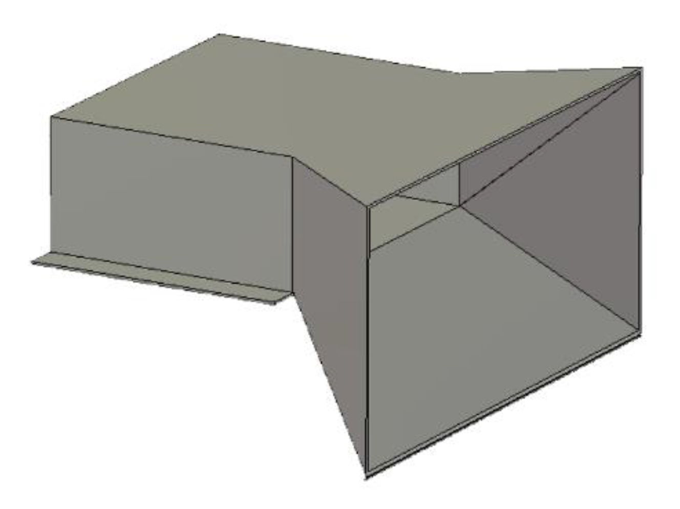
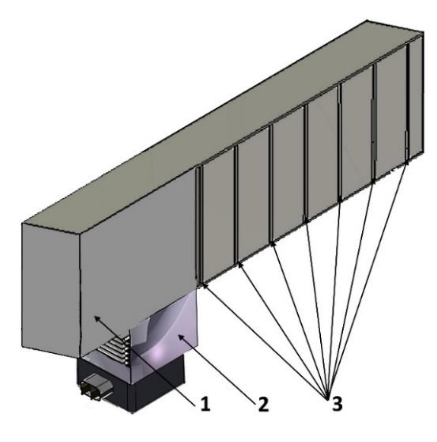
The analysis of the efficiency indicators and of the microwave electromagnetic field distribution has been performed, for three radiator types, namely: horn radiator (see
Figure 2), 55×110 rectangular waveguide with slot-type emitters (see
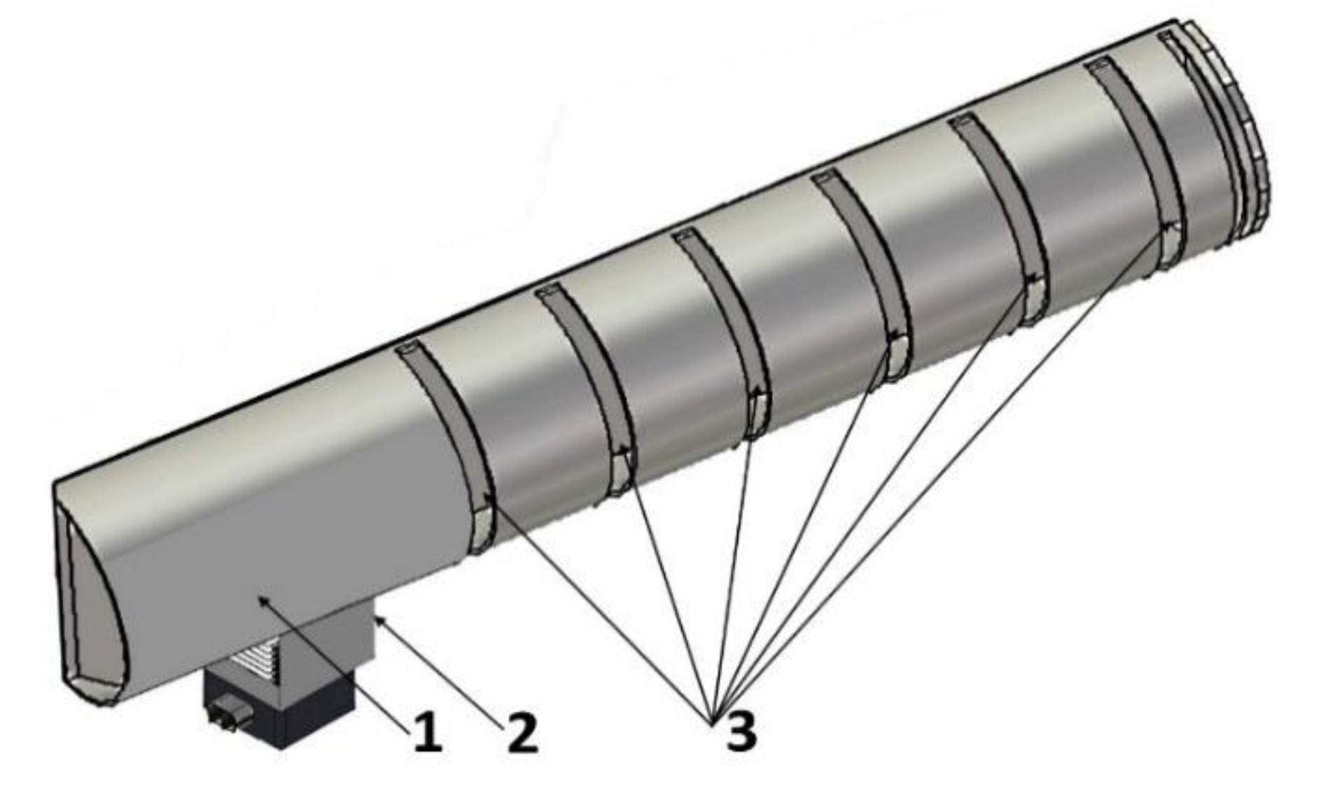
Figure 3) and semicircle waveguide with slot-type emitters (see
Figure 4).
Finite method was applied for mathematical simulation. Finite integration technique (FIT) represents a method of spatial discretization designed for computational solution of electromagnetic field problems, in both time and frequency domains. It makes it possible to retain the basic topological properties of continuous equations such as conservation of charge and energy. The main idea of this approach is to apply Maxwell equations in their integral form, to a multilayer grid.
where
E is electric field intensity (V/m),
H is magnetic field intensity (A/m),
B is magnetic induction (T),
D is electric induction (Coulomb/m2),
Г is borderline enclosing a free-form surface (m2),
S is free-form surface (m2),
V is volume (m3),
j is electric current density (A/m3),
l is closed contour (m),
ρ is electric charge density (Coulomb/m3),
t is time (s).
The major advantages of this method include high flexibility in geometric modelling and boundary processing, and the possibility to involve any material distribution and properties of material. Besides, application of correlated binary orthogonal grid in combination with the explicit integrating scheme in time yields effective algorithms in terms of simulation process and storage efficiency.
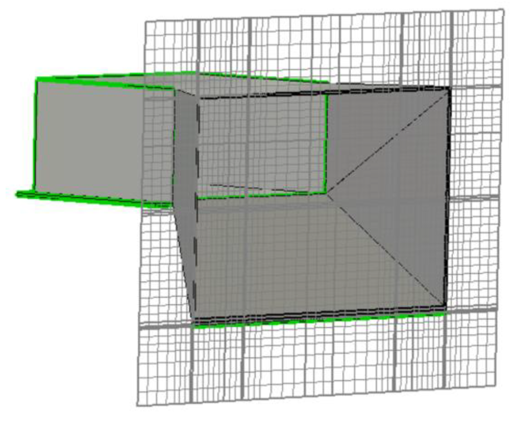
The essence of the method is based on tiling the computational domain into finite number of spatial cells. The cells are built so that they completely fit together, and intersection of two different cells is a void or a polygon with one-dimensional edge, or a point shared by the both cells (see
Figure 5).
Such partitioning scheme yields the final integration grid that is used as the computation array. Therefore, the entire computation domain gets composed of a finite number of elementary cells. Variable electromagnetic fields and flows are normally located along the elementary lines or elementary planes. Similarly, intensities directed along other edges of the cell can be calculated. The aggregate magnetic flow through a plain can be determined as integral of the magnetic flow density through this plane. As a result, electric field densities and magnetic flows of the entire cell complex is represented in a matrix form. Solution of this equation yields the desired variables.
In the process of designing microwave devices with the help of CST Microwave Studio 2019 design, structures in three-dimensional representation are produced by drawing simplest geometric forms (primitives) and by performing logic (Boolean) operations over them [
28].
Effectiveness of radiators was evaluated with the use of the following indicators:
- -
- standing wave ratio (SWR) making it possible to evaluate radiator coherence,
- -
- radiation efficiency characterizing the share of energy transferred through the waveguide from magnetron,
- -
- angular pattern of the microwave field. Radiation directionality diagram is dawn in 3D form which makes it possible to evaluate uniformity of the electromagnetic field distribution, in the radiator output,
- -
- the radiation pattern of the microwave field along the waveguide is perpendicular to the radiation,
- -
- radiated microwave power distribution.
2.2. Features of electromagnetic field transmission by horn waveguides
According to the classification, horn antennas belong to the aperture class antennas. They have emitting elements in form of planar aperture in which angular distribution of the microwave field is achieved. Among advantages of these antennas are design relative simplicity and reliability, convenience of connecting to waveguide transmission lines, rather low energy loss and wide bandwidth [
29,
30]. Horn antennas are applied in a broad frequency interval ranging from decimeter to millimeter waves. Typical horn antenna design structure is a smooth transition interface between the waveguide’s open end and the radiating surface (aperture). The latter is made of large size in order to enhance its radiation directionality and, therefore, to attain better matching between the radiator and the feeder transmission line. The authors used combination of
H-sectorial and pyramidal horns (see
Figure 6a,b). The upper plane of horn has
H-sectorial form while the lower one is made in form of pyramidal horn (see
Figure 6c).
Such form was selected for the sake of possibility to control the direction of electromagnetic field propagation in the grain layer. Since the convective-microwave processing plant is composed of units one of which is shown in
Figure 1, such waveguide design enables to control field directionality depending on the unit location. For instance, in case that grain, from the feed hopper, is loaded into the upper convective-microwave zone downward directed horn is used. It is done to avoid microwave electromagnetic field propagation outside the area of the processing plant when the level of grain, in the feed hopper, drops. In the lower units of the processing plant located close to the receiver hopper, downward directionality of horn has to be insured, as well. In this case, relevant conditions for electromagnetic field distribution over the bottom of the processing plant are provided.
The opposite direction of the field of the horns in two consecutive zones is used in the lower half of the processing plant, where the moisture content in the processed grain becomes lower and, consequently, the intensity of the microwave field acting on the grain layer can be increased.
Directional gain (DG) of aperture-type antenna is defined from the following formula [
31]:
where
S is aperture area surface (m
2),
λ is radiation wavelength (m),
γ is aperture efficiency (AE) depending on the field amplitude and phase distribution in radiator aperture (a.u.).
The maximum value of AE (γ = 1) is attained in conditions of uniform and coherent excitation of the aperture.
In a first approximation, field amplitude distribution in the horn aperture has sinusoidal form, in the plane of vector H [
32]:
where
B is aperture area dimension along axis
y (m),
E(y) is electromagnetic field intensity along axis y, (V/m);
Emax is the maximum value of electromagnetic field, in the aperture (V/m)
Phase of the field in the aperture changes in accordance with a nearly square law because of curvilinear form of the wave edge surface. The change in the direction of the electromagnetic field (and its power) at the output of the horn radiator can be described by a second-order equation. Phase displacement has its maximum Ф
max on the borders of the aperture area and equals to:
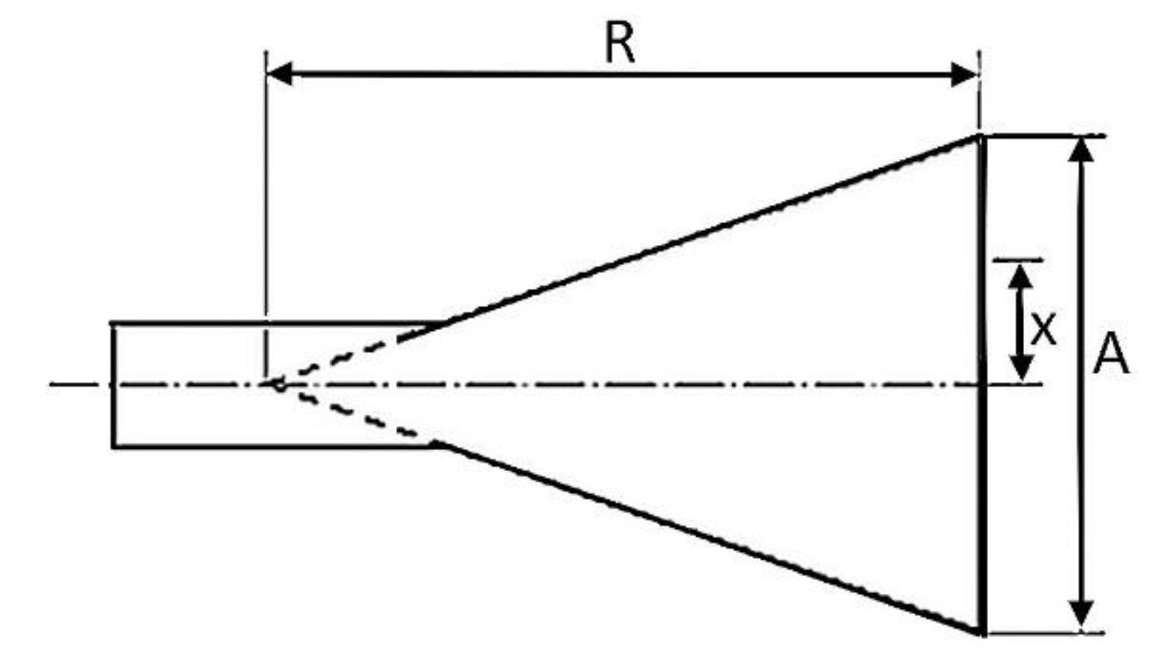
For constant length
R of the horn, aperture area
S grows with aperture size
А (see
Figure 7) resulting in decreasing AE due to the increasing phase nonuniformity.
DG of horn antennas attains its maximum for certain values of the aperture size (phase error on the aperture edge). This phase error is –3π⁄4, for
Н-sectorial horn. Such horns are called optimal horns [
33]. Dimensions of optimal horns are defined by substitution variables in formula (7) with the above values of phase displacement on the aperture edge:
, for
Н-sectorial horn. Wavelength for radiation frequency f=2.45 GHz equals to 122 mm. In accordance with the horn design R = 80 mm. This is the distance between the magnetron emission point and the front edge of the horn. Therefore, aperture size
= 171 mm. For the reason of limiting dimensions of the assembly where power supply units and magnetrons have to be mounted value
A = 155 mm was selected.
In this case, horn aperture efficiency does not attain its maximum value. It has to be also born in mind that, in the selected horn aperture design, combination of H sectoral and pyramidal horn is used. That is why more correct evaluation of the electromagnetic field distribution in the horn output can be done on the basis of mathematical simulation results.
2.3. Features of electromagnetic field transmission by rectangular waveguides
The outlay of the waveguide subject to the electromagnetic field distribution studies is shown in
Figure 3. In these studies, magnetron with operating frequency 2.45 GHz was selected as the source of microwave energy. Generator wavelength equals to [
34]:
where
с = 3⋅10
8 m/s is speed of light.
For frequency value 2.45 GHz, wavelength is
λ = 0.122 m = 122 mm.
In microwave communication devices, selection of particular wave types such as, for example, H
10, H
01, E
11 is essentially important [
35]. Contrariwise, wave type selection is of no importance when microwave electromagnetic field is used for heating purposes. It is more critical to ensure lossfree transfer of the radiation to the load. That is why the focus was made on multiwave guides. Besides, dielectric strength of the waveguide can be increased, and the energy loss can be reduced by increasing the dimensions of the waveguide in relation to its length [
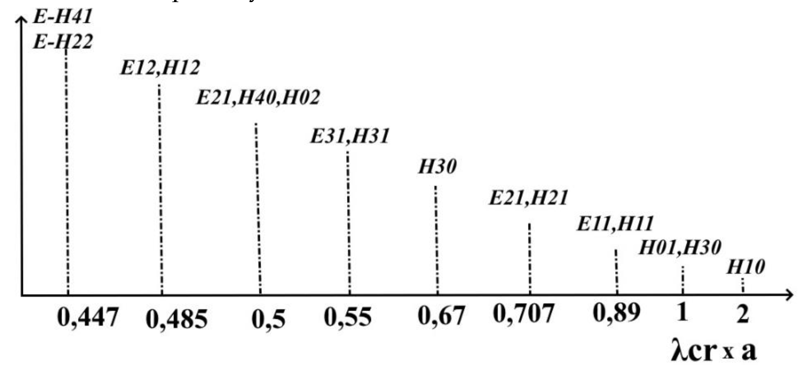
34]. We will consider wave types capable to transfer along rectangular waveguides. In this regard let us draw the diagram of critical wavelengths for magnetic- and electric-type oscillations. Assuming
where
а and
b are, respectively, dimensions of the larger and the smaller walls of the rectangular waveguide.
Critical lengths for of magnetic- and electric-type waves are defined from the following relationship [
35]:
where m and n are oscillation type indexes H
mn (E
mn). For
Е wave,
m≥1,
n≥1. For
H-wave, one of the two indexes may be equal to zero [
20].
Calculating critical waves for various oscillation types were performed with the use of MATLAB software [
36]. It was assumed in calculations that
а = 1. While drawing the diagram shown in
Figure 8, calculated data were multiplied by value
a.
To ensure the possibility of propagation of all modes in waveguides, the following conditions must be observed:
For waves of H
10 type, equation (7) can be written in the following form:
Dimensions of rectangular waveguides stipulated in GOST 51914-2002, for frequencies close to those discussed in this article, are as follows:
Cross-section shall be 110.00×55.00 mm and 90.00×45.00, respectively, for the frequency ranges from 1.72 GHz to 2.59 GHz and from 2.14 GHz to 3.2 GHz.
Taking into account that, in the processing plant, microwave field has to be distributed as homogeneously as possible, in the grain layer, we assume that waveguide cross-section 110×55 to a greater extent corresponds to this requirement. Therefore, critical wavelength for this waveguide is . It means that selected waveguide dimensions comply with the requirement (11).
2.4. Features of electromagnetic field transmission by semicircular waveguides
Selection of semicircle waveguide is, first of all, defined by the specific technological features of the convective-microwave processing. Technical implementation of this method requires drying agent supply into the area of material processing. With regard to the design convenience, waveguides of semicircle cross-section are an optimal choice.
Critical wavelength in circular waveguide, for type E
mn wave, can be found from the following equation [
27]:
or, in application to type
wave:
where
r is waveguide radius,
are roots of Bessel functions and of their derivatives, for type E wave,
are roots of Bessel functions and of their derivatives, for type H wave.
Wave types transferred in circular waveguide, depending on its radius, are presented in
Figure 9.
In waveguide of semicircle cross-section, as well as in circular waveguide, critical wavelength, for type H wave, λcr=3.41r. For type E wave, λcr=1.64r. It means that, for inner radius 50 mm of the waveguide, critical wavelength, for type H wave, λcr=170 mm, while for type E wave, λcr=82 mm. It appears from the values of critical wavelength, for waveguide radius 50 mm, that propagation of electromagnetic waves of E11 type, in such waveguides, is problematic. Therefore, mainly waves of type H11 will go through this waveguide
3. Results
3.1. Studying microwave electromagnetic field distribution in horn antennas
Mathematical simulation of the microwave electromagnetic field distribution process was performed with the use of CST Microwave Studio software. The outlay of the horn-type waveguide model used in the mathematical simulation process is shown in
Figure 6c.
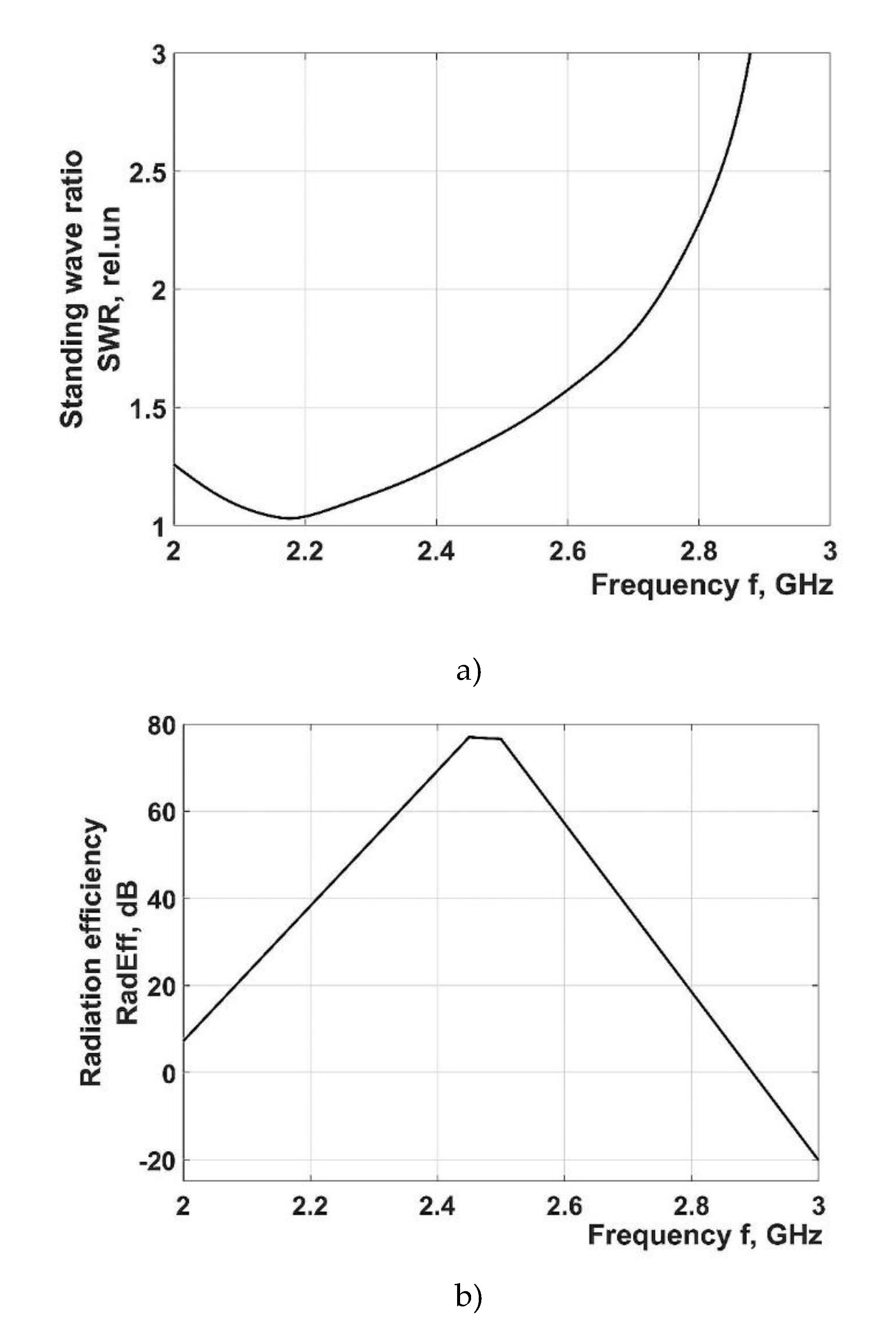
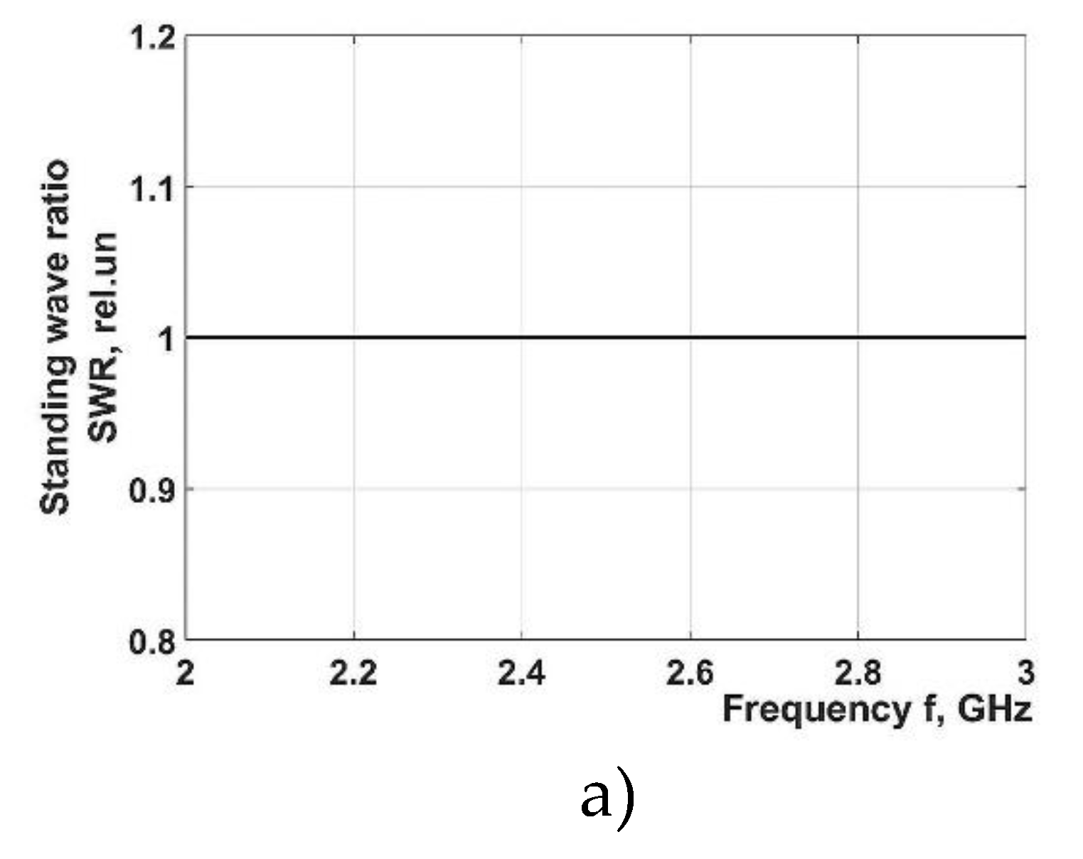
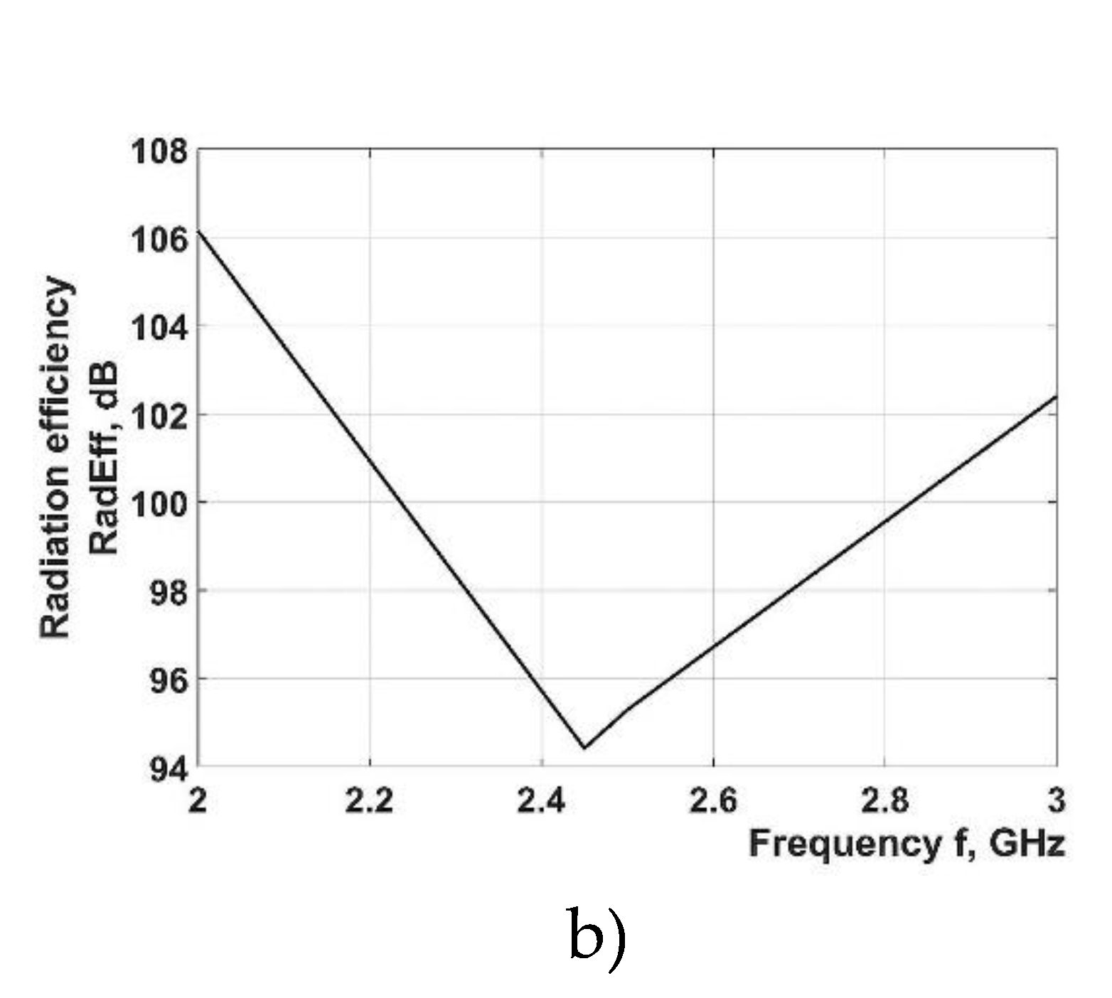
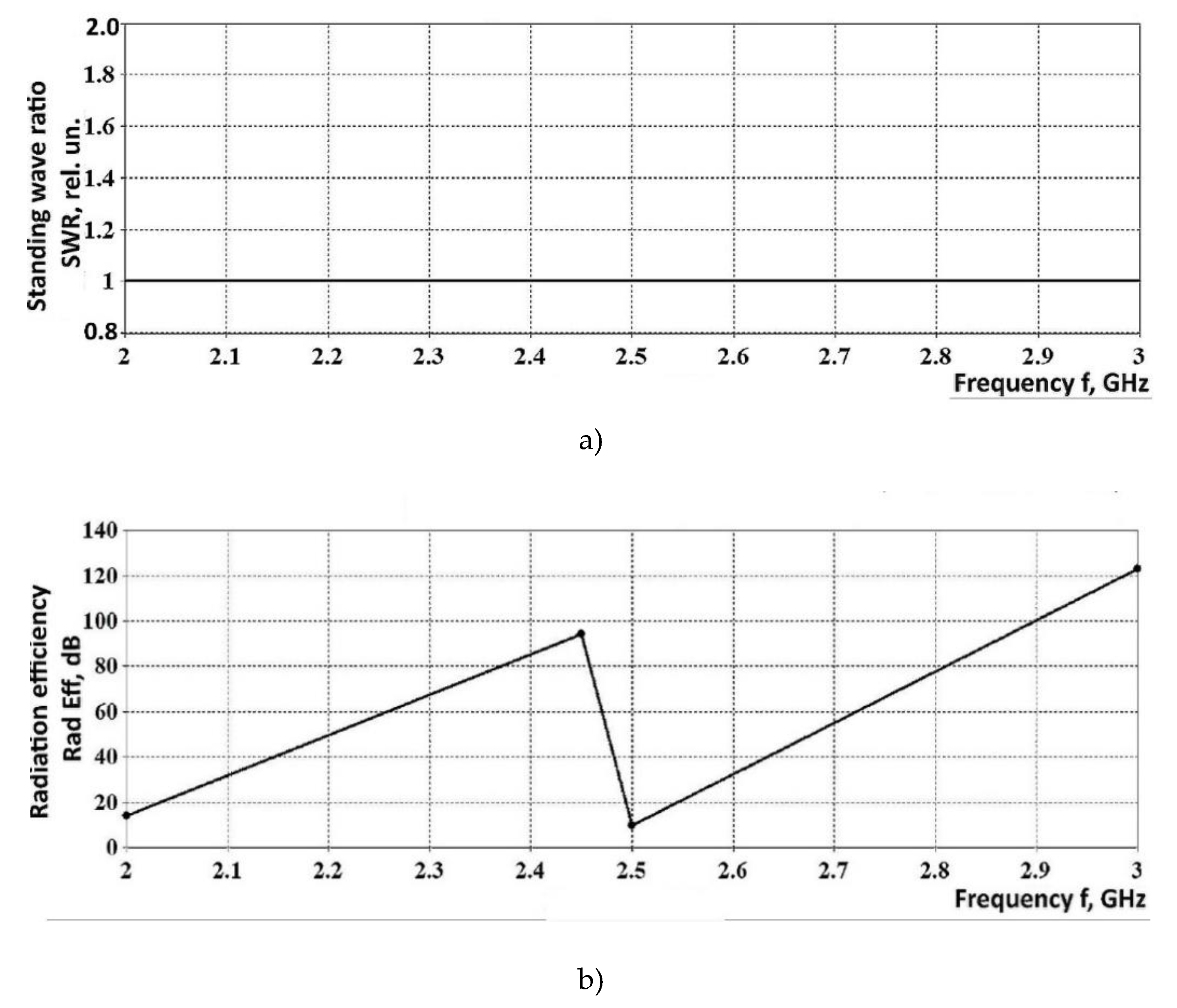
Frequency range from 2 GHz to 3 GHz with central points of 2.45 and 2.5 GHz was selected for mathematical simulations. Owing to these a number of dependences was deduced, presented in
Figure 10a,b.
Figure 10a,b show, respectively, the graph for frequency dependence of the standing wave ratio (SWR) and that of radiation efficiency, for the selected horn-type waveguide.
Results of the mathematical simulation show that SWR values fall close to 1.3, for operating radiation frequency of the magnetron, which is a positive indicator providing evidence of sufficient radiator coherence. Radiation efficiency has a maximum, in the radiation frequency range of magnetrons, demonstrating acceptable level of radiator coherence, as well.
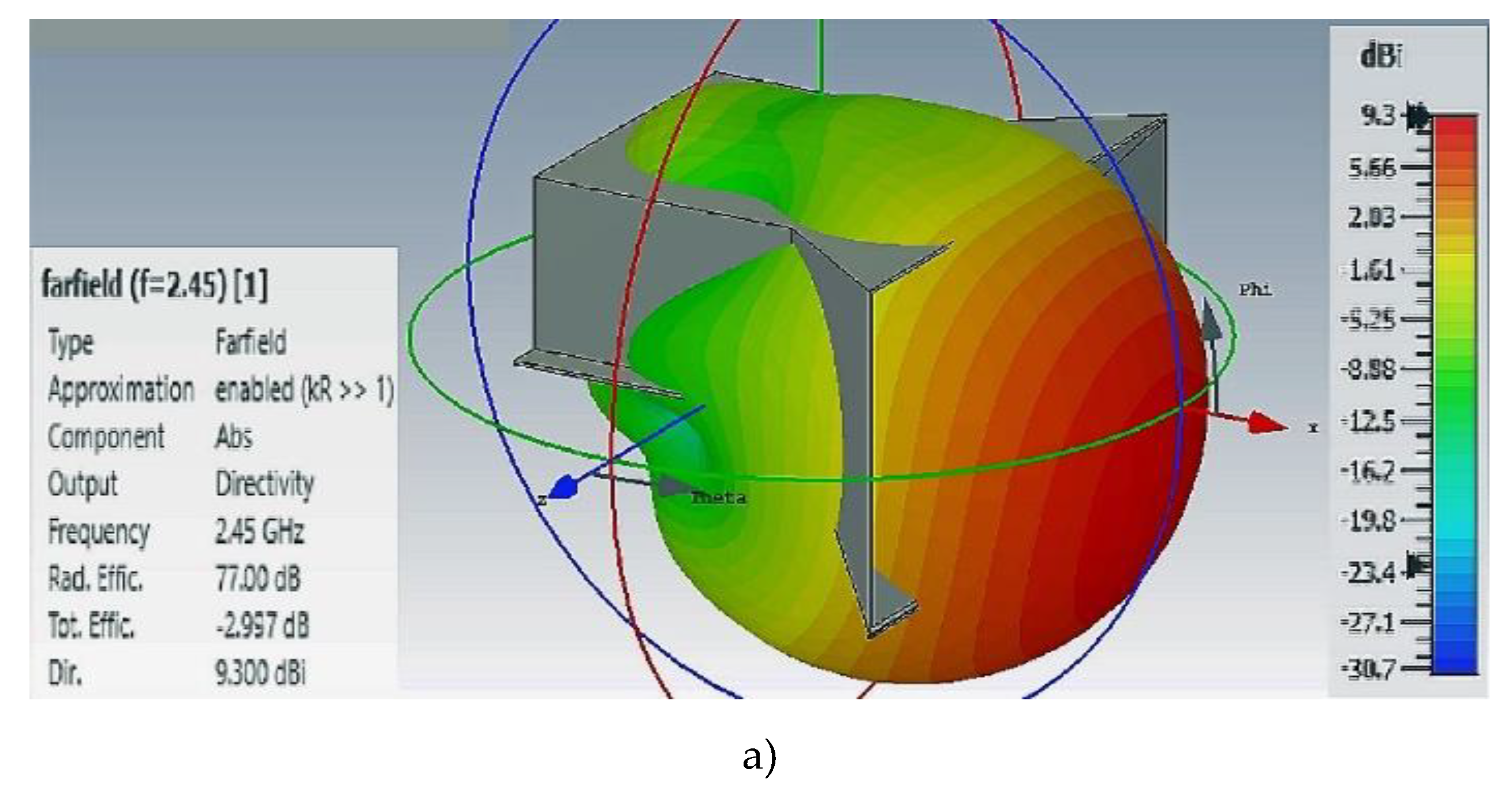
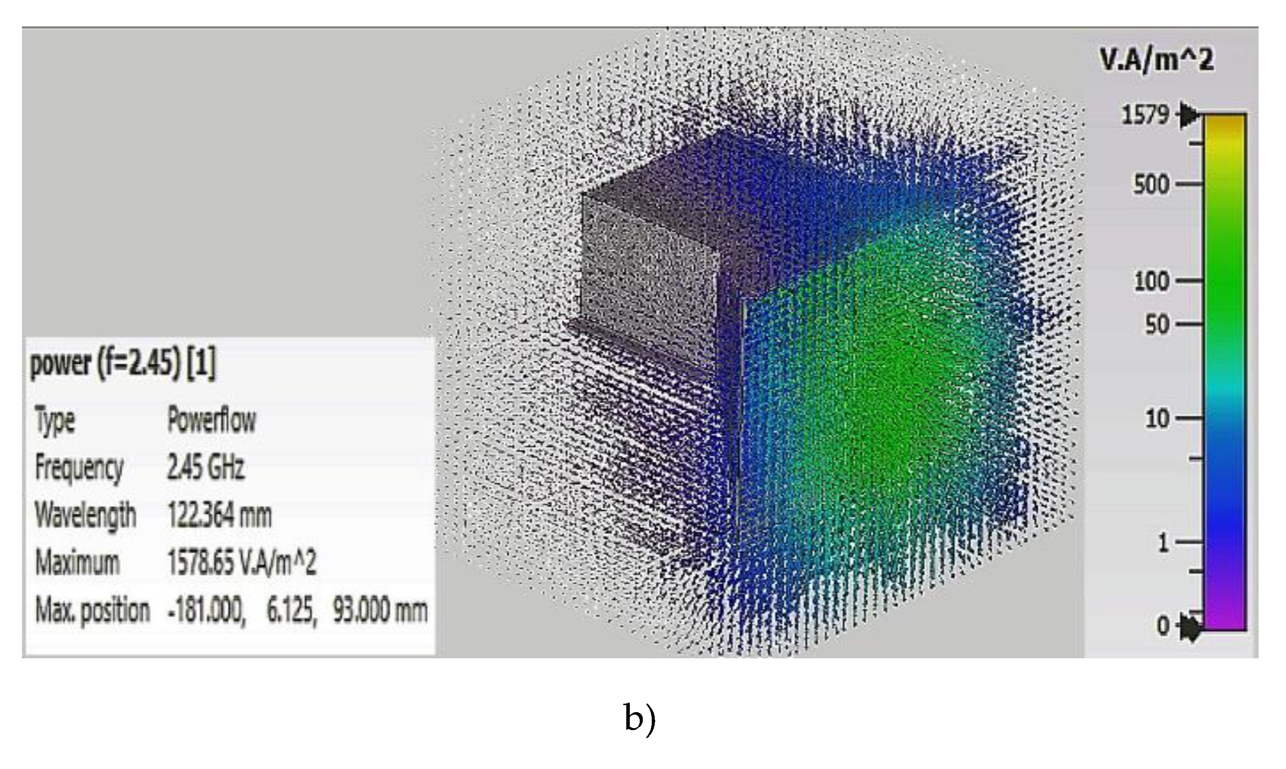
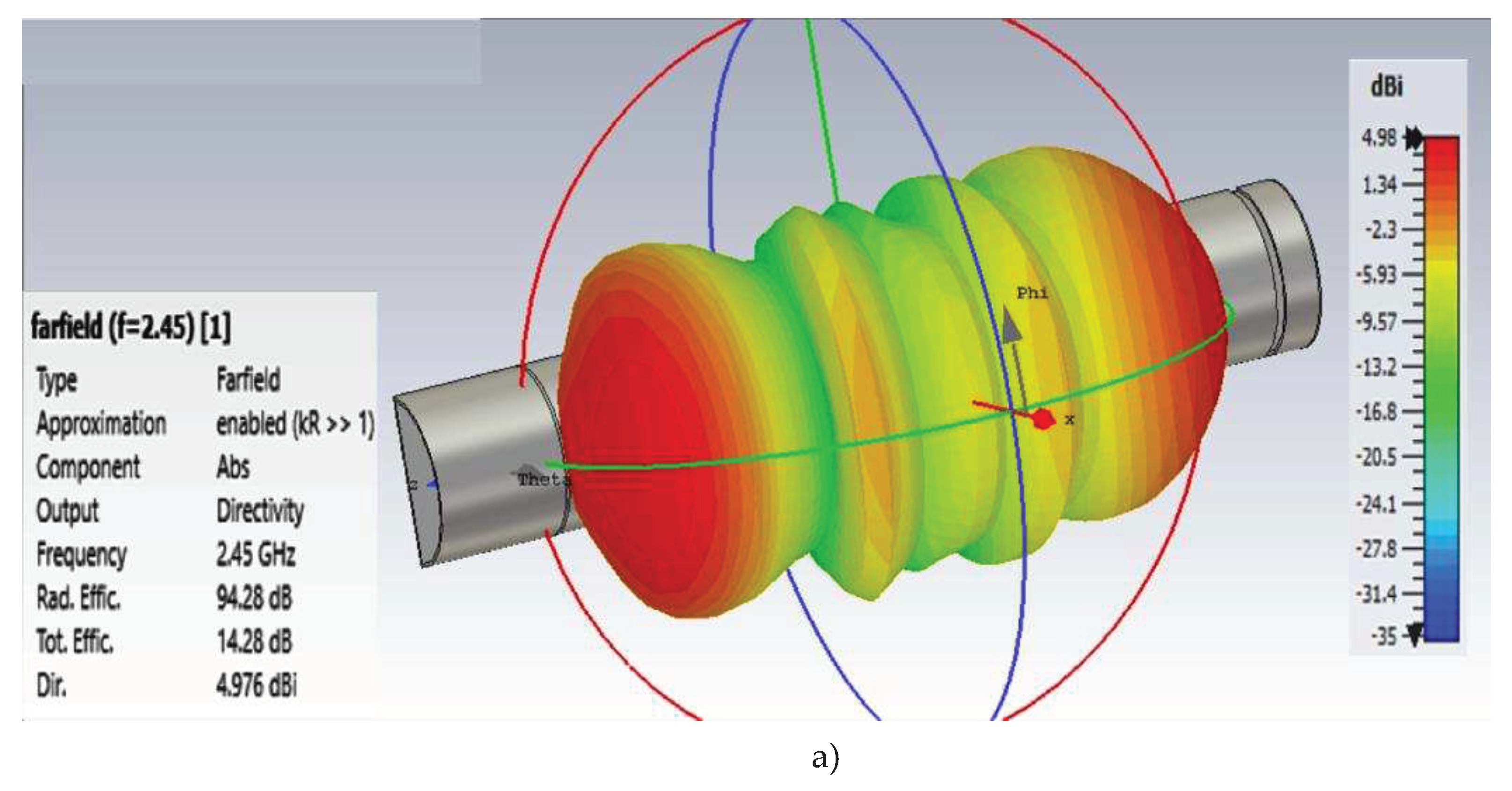
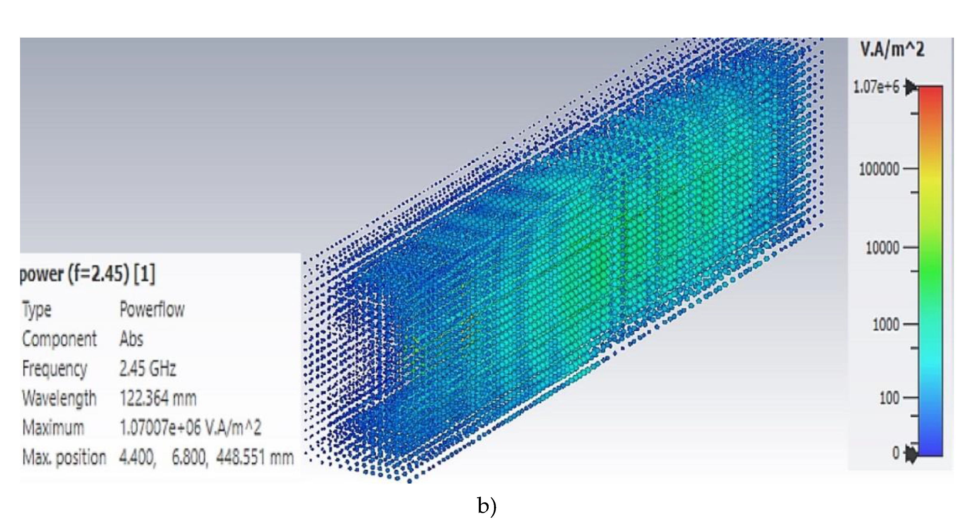
In order to evaluate electromagnetic field spatial distribution, 3D dependences were calculated. They are presented in
Figure 11.
Results of the 3D mathematical simulations show that there exists substantial nonuniformity of the electromagnetic field density distribution both along the perimeter of the horn aperture area and in the radiation propagation direction.
Therefore, application of horn-type waveguides ensures rather high values of SWR (1.3) and high radiation efficiency but the uniformity of the microwave field density distribution has to be improved.
Earlier performed experimental studies [
24] have shown that energy consumption of the grain drying process, in convective-microwave zones, essentially depends on the drying agent parameters and on the method of its supply into the grain drying area. Energy consumption can be minimized when the directions of microwave field propagation into the grain layer and that of the drying agent coincide with each other [
24]. In this case, a certain grade of microwave field distribution uniformity and that of drying agent concentration, in the grain layer, has to be ensured. This condition is hard to fulfill for the design option of convective-microwave zone with horn-type waveguides. That is why an attempt was made to develop a waveguide design capable to comply with the above conditions.
3.2. Studies of rectangular waveguides with slot radiators
On the basis of this waveguide, slot radiator was designed [
39,
40,
41]. For this purpose, transverse slots were cut in the broad waveguide’s wall. The transverse slot in the broad wall of the waveguide gets excited by the direct-axis component of the current. With the account of the required volume of the section, radiator length of 400 mm was selected. Slots in the backside of the radiator are spaced 1/2
λ apart (see
Figure 3).
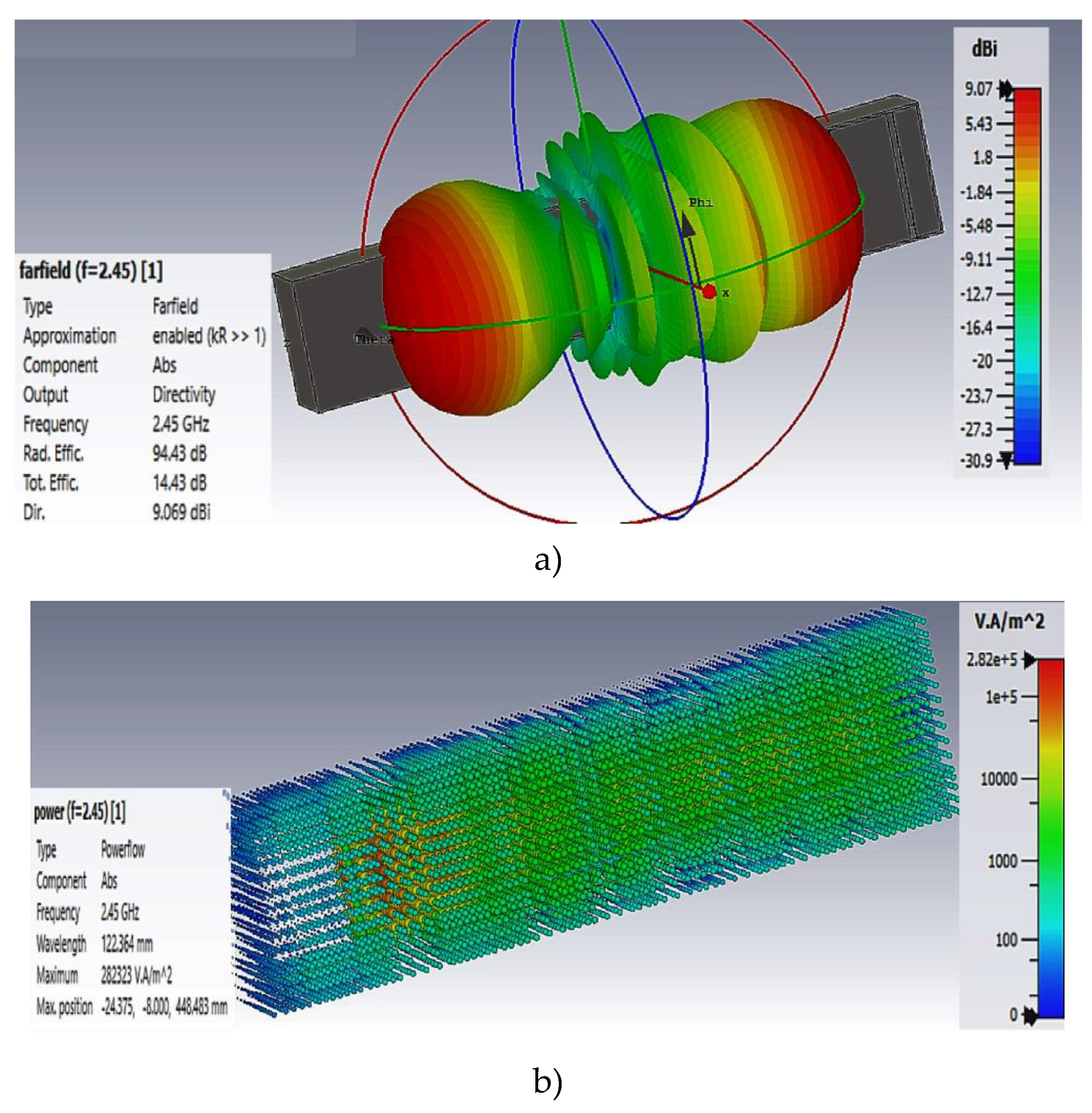
Radiator parameters were first conformed and then were input into CST Microwave Studio software for mathematical simulation of the electromagnetic field distribution from the radiator’s slots. The results of this simulation are presented in
Figure 12 and
Figure 13.
Mathematical simulation results show that application of rectangular waveguide makes it possible to achieve better homogeneity of the electromagnetic field distribution. Besides, rectangular waveguide features SWR equal to 1 and increased radiated power values.
That is why the use of rectangular 55×110 waveguide in convective-microwave zones for processing grain is more preferable.
Apart from the rectangular 55×110 waveguide, mathematical simulation of the electromagnetic field distribution was performed for the waveguide of semicircle cross-section (circular sector) with slot radiator (see
Figure 4).
3.3. Studies of semicircle waveguide with slot radiator
Figure 14 and
Figure 15 show mathematical simulation results for microwave field emission conditions in the output of semicircle waveguide with slot radiator.
3.4. Comparison of radiation patterns for the three types of emitters studied
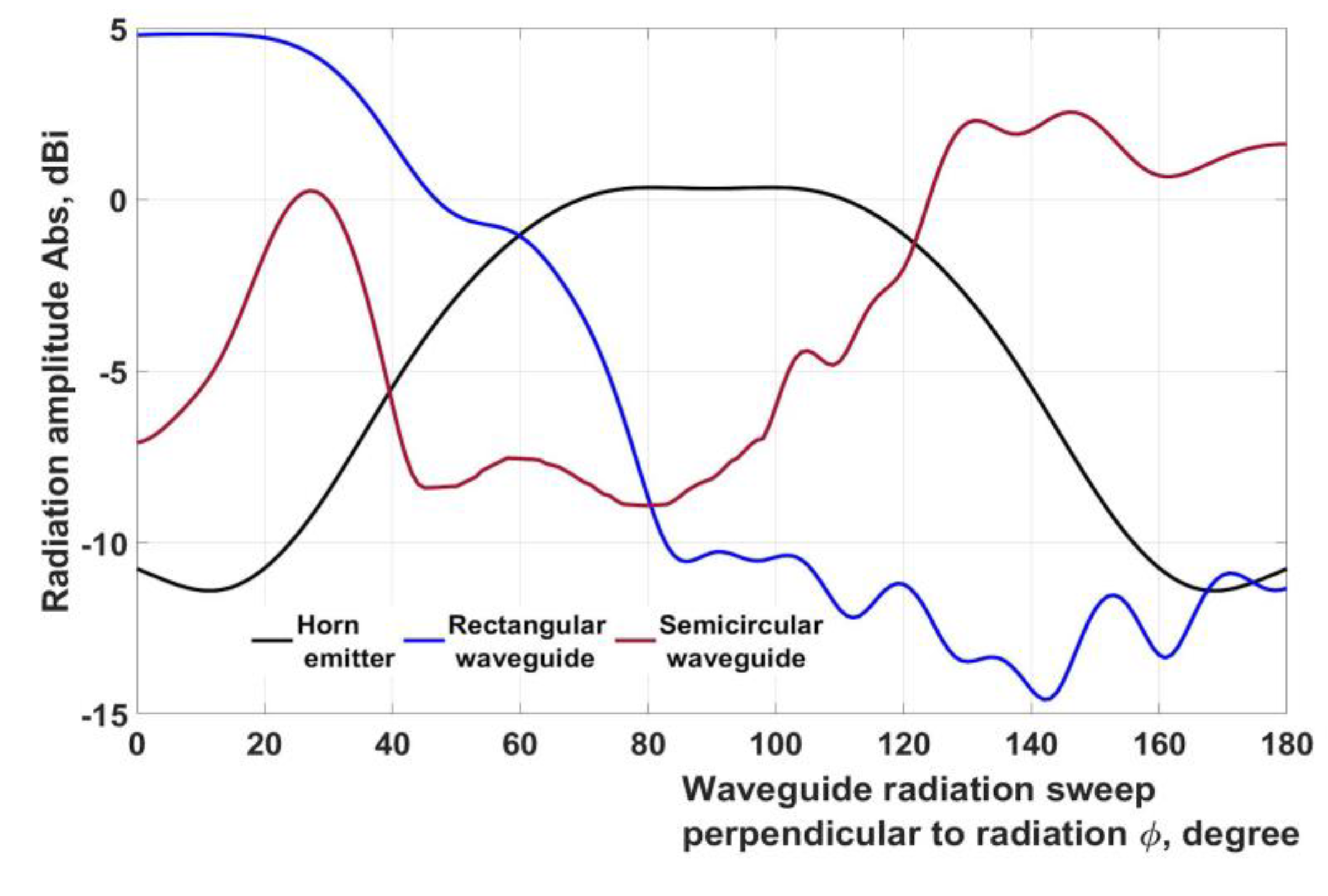
A comparison of the radiation efficiency values for the three types of waveguides under study showed that the semicircular waveguide has the best data. However, the distribution of radiated power shown in Figures 11b, 13b, 15b does not fully allow us to estimate the change in the distribution of the electromagnetic field along the waveguides. Therefore,
Figure 16 shows graphs of directional patterns for three types of waveguides.
Figure 16 shows radiation patterns along the waveguide perpendicular to the radiation. The radiation patterns show that the most uniform distribution of the microwave field is observed in a semi-circular waveguide. This allows you to make a choice in his favor.
4. Discussion
Results of simulations show that a proper matching between the semicircular waveguide with the slot radiators make it possible to attain values of SWR = 1, over the entire frequency range from 2 GHz to 3 GHz. Radiation efficiency of the electromagnetic field was 94.28 dB (see
Figure 14b) compared to 94.43 dB, for 55×110 rectangular waveguide. With the assumption that the radiation efficiency of semicircular waveguide was due to the absence of type
E11 waves we can conclude that their share is just 0.15 dB which does not exceed 0.16 % of the aggregate power transmitted through the waveguide.
It follows from the simulation results that radiation efficiency for rectangular waveguides has more uniform character in a wide range of waves. Radiation efficiency reduction in the range from 2 GHz to 3 GHz does not exceed 10 %. In semicircular waveguides, radiation efficiency changes stepwise, in this frequency range, and has its maximum value at its standard frequency 2.45 GHz. Therefore, operation conditions of magnetrons have to be tightly controlled avoiding operation modes leading to their overheating, when semicircular waveguides are applied.
The overall efficiency of microwave energy transmission is 14.28 dB, for semicircular waveguide (see
Figure 15a), while that of rectangular waveguide is 14.43 dB (see
Figure 13a). At the same time, their radiation directionality features better uniformity compared to 55×110 rectangular waveguides (see
Figure 16).
In consideration of the issues discussed above we may conclude that the application of more easily manufactured semicircular waveguides does not affect indicators of transmission efficiency and those of electromagnetic field distribution uniformity.
5. Conclusions
Application of horn-type waveguides in convective-microwave processing plants makes it possible to manufacture rather convenient processing equipment for processing grain. In operating frequency range, their SWR is 1.3, for radiation efficiency 78 dB. However, such waveguides do not provide sufficient uniformity of microwave field distribution in their output affecting the efficiency of grain processing.
The use of rectangular 55×110 waveguides with slot radiator makes it possible to ensure more uniform radiation of electromagnetic field in the entire spectrum of wave types. Their SWR equals to 1, and radiation efficiency amounts to 94.43 dB. At the same time, their application requires further design development related to the issues of the heat-carrier supply to the processing area.
Semicircular waveguides with slot radiator feature SWR equal to 1 over the frequency rangeе from 2 GHz to 3 GHz. Their radiation efficiency is 94.28 dB. Electromagnetic field distribution homogeneity of such waveguides is better compared to rectangular waveguides. Besides, the problem of the heat-carrier supply into the area of grain processing can be solved more easily, for circular waveguides.
Author Contributions
Conceptualization, A.N.V.; methodology, D.B.; software, validation, formal analysis, A.A.V., A.N.V. and D.B.; investigation, A.A.V.; resources, data curation, A.N.V.; writing—original draft preparation, writing—review and editing, visualization, A.A.V. ; supervision, project administration, A.N.V.; funding acquisition, A.A.V. All authors have read and agreed to the published version of the manuscript.
Funding
This research was supported by Federal Scientific Agroengineering Center VIM (RF state assignment No FGUN-2022-0004)
Conflicts of Interest
The authors declare no conflict of interest.
References
- Lermen, Fernando Henrique; Duarte Ribeiro, Jose Luis; Echeveste, Marcia Elisa; et al. Sustainable offers for drying and storage of grains: Identifying perceived value for Brazilian farmers. Journal of stored products research. Volume: 87. Article Number: 101579 Published: MAY 2020.
- Coradi, Paulo Carteri; Calegare Lemes, Angelo Francisco; Muller, Amanda; et al. Silo-dryer-aerator in fixed and thick layer conceptualized for high quality of grains applied in different social scales post-harvest: modeling and validation. Drying technology. Early Access: DEC 2020.
- Binelo, Manuel O.; Faoro, Vanessa; Kathatourian, Oleg A.; et al. Airflow simulation and inlet pressure profile optimization of a grain storage bin aeration system. Computers and electronics in agriculture. Volume: 164. Article Number: 104923. Published: SEP 2019. [CrossRef]
- Khatchatourian, Oleg A.; Binelo, Manuel O.; Faoro, Vanessa; et al. Three-dimensional simulation and performance evaluation of air distribution in horizontal storage bins. Biosystems engineering. Volume: 142. Pages: 42-52. Published: FEB 2016. [CrossRef]
- Boron, Dominika; Kaminska-Pekala, Anita. Grained material drying in silo dryer. Przemysl chemiczny. Volume: 98. Issue: 12. Pages: 1913-1916. Published: DEC 2019.
- Domingues de Camargo, Lucas Leao; Gomes de Souza, Luciane Franquelin; Nitz, Marcello. Study of tray and pulsed fluidized bed drying of brewer's spent grain. Chemical industry & chemical engineering quarterly. Volume: 25. Issue: 3. Pages: 229-237. Published: JUL-SEP 2019.
- Meesukchaosumran, Supitchar; Chitsomboon, Tawit. Dimensionless variable groups for the free-fall grain dryer. International journal of agricultural and biological engineering. Volume: 12. Issue: 4. Pages: 197-204. Published: JUL 2019.
- Nguyen Van Hung; Martinez, Romualdo; Tran Van Tuan; et al. Development and verification of a simulation model for paddy drying with different flatbed dryers. Plant production science. Volume: 22. Issue: 1. Special Issue: SI. Pages: 119-130. Published: JAN 2 2019. [CrossRef]
- Rudobashta, S.; Zueva, G.; Zuev, N. Mathematical Modeling and Numerical Simulation of Seeds Drying Under Oscillating Infrared Irradiation Conference: 13th Polish Drying Symposium (PDS) Location: Kolobrzeg, POLAND Date: SEP 05-06, 2013. Drying technology Volume: 32 Issue: 11 Pages: 1352-1359 Published: 2014.
- Granella, Suian Jose; Bechlin, Taise Raquel; Christ, Divair; et al. Kinetic and physicochemical properties of drying-ozonation process on wheat grain. Journal of food processing and preservation. Volume: 43. Issue: 9. Published: SEP 2019. [CrossRef]
- Yogendrasasidhar, D.; Setty, Y. Pydi Drying kinetics, exergy and energy analyses of Kodo millet grains and Fenugreek seeds using wall heated fluidized bed dryer. Energy. Volume: 151. Pages: 799-811. Published: MAY 15 2018. [CrossRef]
- Albini, Geisa; Freire, Fabio Bentes; Freire, Jose Teixeira Barley: Effect of airflow reversal on fixed bed drying. Chemical engineering and processing-process intensification. Volume: 134. Pages: 97-104. Published: DEC 2018.
- Liu Chunshan; Chen Siyu; Jiang Yongcheng; et al. The Principle and Experimental Research of New Type of Recirculating Grain Dryer. Conference: International Conference on Robots & Intelligent System (ICRIS). Pages: 453-456. Location: Zhangjiajie, Peoples R China. Date: AUG 27-28, 2016. [CrossRef]
- Hemis, Mohamed; Gariepy, Yvan; Choudhary, Ruplal; et al. New coupling model of microwave assisted hot-air drying of a capillary porous agricultural product: Application on soybeans and canola seeds. Applied thermal engineering Volume: 114 Pages: 931-937. Published: MAR 5 2017. [CrossRef]
- Turkoglu, T.; Baykal, H.; Yuksel, H.; et al. The intermittent drying of wheat by microwave and fluidized bed drying. Conference: 21st International Drying Symposium (IDS) Location: Valencia, SPAIN Date: SEP 11-14, 2018. Pages: 1543-1550.
- Rebecca M. Bruce; Griffiths G. Atungulu; Sammy Sadaka; Deandrae Smith Impact of specific energy input of a 915 MHz microwave dryer on quality, functional, and physicochemical properties of different rice cultivars. Cereal Chemistry. - 2021-05-25 | Journal article. [CrossRef]
- Abano, Ernest Ekow Kinetics and Quality of Microwave-Assisted Drying of Mango (Mangifera indica). International Journal of Food Science. - Volume 2016. Article ID 2037029. [CrossRef]
- Walde, S.G.; Balaswamy, K.; Velu, V.; Rao D.G. Microwave drying and grinding characteristics of wheat (Triticum aestivum). Journal of Food Engineering. 55. - 2002.- pp. 271–276. [CrossRef]
- Bespalko V.V. , Buryak Ju.I. Efect of the pre-seeding treatment of seeds with the use of microwave field in combination with growth-promoter and bio-based product on sowing quality and crop productivity of summer barley. Grain legumes and cereal crops. – No. (12). 2014. – P.133-138. (Russ.).
- Kovalev, A.V.; Spiridonov, O.B.; Lysenko, I.E.; Ezhova, O.A. Method and System of Pre-Sowing Microwave Treatment of Agricultural Crop Seeds. International Journal of Engineering Research and Technology. ISSN 0974-3154, Volume 13, Number 1.- 2020. - pp. 3964-3969. [CrossRef]
- Horuz E, Bozkurt H, Karataş H & Maskan M. Simultaneous application of microwave energy and hot air to whole drying process of apple slices: Drying kinetics, modeling, temperature profile and energy aspect. Heat and Mass Transfer 54(2). -2018. - pp. 425-436. [CrossRef]
- Aghilinategh N, Rafiee S, Gholikhani A, Hosseinpur S, Omid M, Mohtasebi S S & Maleki N. A comparative study of dried apple using hot air, intermittent and continuous microwave: evaluation of kinetic parameters and physicochemical quality attributes. Food Science & Nutrition Volume 3, Number 6. - 2020. -pp. 519-526. [CrossRef]
- Vasilyev, Alexey A.; Vasilyev, Alexey N.; Budnikov, Dmitry; Bolshev, Vadim; Shilin, Denis; Shestov, Dmitry Dynamic Arches Destruction by a Bulk Material Flow Separator: A Case Study of the Separator Usage in Microwave Grain Processing Plants Agronomy 2022, 12, 997. [CrossRef]
- Budnikov D.A., Vasilyev A.N., Vasilyev A.A. Designing operation areas of convective-microwave processing plants for grain treatment with the application of dynamoelectric mathematical simulations. - Oryol, 2022. – 348 P. (Russ.).
- Vasiliev, Aleksey N.; Goryachkina, V. P.; Budnikov, Dmitry Research Methodology for Microwave-Convective Processing of Grain. InternationaL journal of energy optimization and engineering. 2020. - Volume: 9. Issue: 2. - Pages: 1-11.
- Z. Y. Li, R. F. Wang, and T. Kudra, Uniformity issue in microwave drying, Drying Technol. - 2011. vol. 29, no. 6, pp. 652–660. [CrossRef]
- Kolesnikov S.M., Trefilov D.N., Dementjev A.N. Designing and optimization of stripline radiator radiator with the application of CST MICROWAVE STUDIO software. - Radioindustry. - 2015. No. 4. - PP. 98-106. (Russ.).
- Fateev A.V. Application of CST MICROWAVE STUDIO SW for calculating microwave antennas microwave devices. – Tomsk. 2014. – 120 P. (Russ.).
- Pozar, David M. Microwave engineering. University of Massachusetts at Amherst. – 2012. – P.756.
- Yanushkevich V.F. Antennas and microwave devices. – Novopolotsk: PGU, 2009. – 360 P. (Russ.).
- Voskresensky D.I., Gostyukhin V.L., Maksimov V. M., Ponomaryov L.I. Microwave devices and antennas. – Moscow: Radiotechnika, 2008. – 384 P (Russ.).
- Pimenov V.Yu., Volmn V.I., Murashov A.D. Technical electrodynamics. M.: Radio and communications, 2002. 536 P. (Russ.).
- Erokhin G.A., Chernyshov O.V., Kozyrev N.D., Kocherzhevsky V.G. Antenna-feeder devices ad propagation of radio waves / eds G.A. Erokhin. – Moscow: Hot line – Telecom, 2004. – 492 P. (Russ.).
- A.B. Smolders, H.J. Visser, U. Johannsen. Modern Antennas and Microwave Circuits - A complete master-level course. Eindhoven University of Technology. – 2020. - P. 189.
- Nechaev Yu.B., Nikolaev V.I., Andreev R.N., Vinokurova N.N. Antennas, microwave devices and their technologies. Voronezh: OAO Concern ‘Sozvezdie’. - 2008. - 629 P. (Russ.).
- Rfrliner M.M. Electrodynamics of microwave. Novosibirsk St. Univ. Novosibirsk. - 2006. - 258 P. (Russ.).
- Inan U.S., Marshall R.A. Numerical Electromagnetics. The FDTD Method. - CUP. – 2011. - 406s.
- Chapman, S. J. MATLAB programming for engineers. Cengage Learning, 2015.
- Petrov R.V. Studies of magneto-electric slot-type resonator for microwave frequency range. – Engineering Physics. 2012. No 1. С. 33-38. (Russ.).
- Zavaliy A.A., Volozhaninov S.S., Volozhaninov N.V. Designing slot-type microwave radiator for treatment soil, seeds and plants. In collected book: Innovative technologies in science and education (Conf. ‘ITNO 2022’). collection of research papers of the Х Jubilee Int. research-to-practice conference. Rostov-on-Don, 2022. P.P. 69-74. (Russ.).
- Topolski, John Andrew Computational Analyses of High Power Microwave Slotted Array Antennas for Mobile Applications. B.S., Electrical Engineering, United States Naval Academy, 2005. – p.179.
- Smolders, A.B.; Visser, H.J; Johannsen, U. Modern Antennas and Microwave Circuits - A complete master-level course. Eindhoven University of Technology. John Wiley & Sons Ltd. – 2022. – P. 551.
Figure 1.
Outlay of convective-microwave zone for grain processing: (1) casing of convective-microwave unit; (2) waveguides; (3) magnetrons; (4) waveguide output gate.
Figure 1.
Outlay of convective-microwave zone for grain processing: (1) casing of convective-microwave unit; (2) waveguides; (3) magnetrons; (4) waveguide output gate.
Figure 2.
Outlay of the horn-type radiator.
Figure 2.
Outlay of the horn-type radiator.
Figure 3.
Outlay of 55×110 waveguide with slot-type emitters: (1) waveguide casing; (2) magnetron; (3) slot-type emitters spaced at intervals of ½ λ.
Figure 3.
Outlay of 55×110 waveguide with slot-type emitters: (1) waveguide casing; (2) magnetron; (3) slot-type emitters spaced at intervals of ½ λ.
Figure 4.
Outlay of semicircle waveguide with slot-type emitters: (1) waveguide casing; (2) magnetron; (3) slot-type emitters spaced at intervals of ½ λ.
Figure 4.
Outlay of semicircle waveguide with slot-type emitters: (1) waveguide casing; (2) magnetron; (3) slot-type emitters spaced at intervals of ½ λ.
Figure 5.
Example of tiling the space in the waveguide output into cells.
Figure 5.
Example of tiling the space in the waveguide output into cells.
Figure 6.
Horn antennas and the antenna used in the processing plant under studies [
13]: (
а) H-sectorial horn; (
b) pyramidal horn; (
c) combined-type horn.
Figure 6.
Horn antennas and the antenna used in the processing plant under studies [
13]: (
а) H-sectorial horn; (
b) pyramidal horn; (
c) combined-type horn.
Figure 7.
Dimensions used for calculating distortions in the horn aperture [
30].
Figure 7.
Dimensions used for calculating distortions in the horn aperture [
30].
Figure 8.
Diagram for oscillation types transferred in the waveguide.
Figure 8.
Diagram for oscillation types transferred in the waveguide.
Figure 9.
Wave types transferred in circular waveguide.
Figure 9.
Wave types transferred in circular waveguide.
Figure 10.
Frequency dependences obtained in the course of mathematical simulations made for microwave field in horn radiator: (a) Frequency dependence for standing wave ratio (SWR) of the horn-type radiator; (b) Frequency dependence for radiation efficiency of the horn-type radiator.
Figure 10.
Frequency dependences obtained in the course of mathematical simulations made for microwave field in horn radiator: (a) Frequency dependence for standing wave ratio (SWR) of the horn-type radiator; (b) Frequency dependence for radiation efficiency of the horn-type radiator.
Figure 11.
3D angular pattern and distribution of radiated microwave power for horn-type waveguide: (a) 3D angular pattern for microwave electromagnetic field; (b) 3D distribution of the radiated microwave field.
Figure 11.
3D angular pattern and distribution of radiated microwave power for horn-type waveguide: (a) 3D angular pattern for microwave electromagnetic field; (b) 3D distribution of the radiated microwave field.
Figure 12.
Frequency dependences obtained by mathematical simulation for microwave field in rectangular (55×110) radiator: (a) Frequency dependence of the standing wave ratio (SWR) for rectangular slot type radiator; (b) Frequency dependence of the radiation efficiency for rectangular slot radiator.
Figure 13.
3D angular patterns of directionality and distribution of radiated power for rectangular 50×110 waveguide: (a) 3D angular patternа of microwave electromagnetic field for rectangular slot-type radiator; (b) 3D diagram of microwave field density distribution for rectangular slot-type radiator.
Figure 14.
Efficiency indicators for semicircle waveguide: (a) standing wave ratio; (b) radiation efficiency.
Figure 14.
Efficiency indicators for semicircle waveguide: (a) standing wave ratio; (b) radiation efficiency.
Figure 15.
Results of 3D mathematical simulations for microwave field radiation in the output of semicircle waveguide with slot radiator: (a) 3D angular pattern for microwave electromagnetic field; (b) 3D density distribution of radiated microwave field.
Figure 15.
Results of 3D mathematical simulations for microwave field radiation in the output of semicircle waveguide with slot radiator: (a) 3D angular pattern for microwave electromagnetic field; (b) 3D density distribution of radiated microwave field.
Figure 16.
Radiation patterns for the three types of waveguides under study.
Figure 16.
Radiation patterns for the three types of waveguides under study.
|
Disclaimer/Publisher’s Note: The statements, opinions and data contained in all publications are solely those of the individual author(s) and contributor(s) and not of MDPI and/or the editor(s). MDPI and/or the editor(s) disclaim responsibility for any injury to people or property resulting from any ideas, methods, instructions or products referred to in the content. |
© 2023 by the authors. Licensee MDPI, Basel, Switzerland. This article is an open access article distributed under the terms and conditions of the Creative Commons Attribution (CC BY) license (http://creativecommons.org/licenses/by/4.0/).

