1. Introduction
The digital broadcasting and communication industries are undergoing advancements to provide high-quality broadcasting services. In response to these changes, the Advanced Television Systems Committee (ATSC) has established ATSC 3.0 as the standard system for next-generation broadcasting systems [
1,
2]. The physical layer of the ATSC 3.0 system was designed to enhance flexibility, robustness, and spectral efficiency compared to the existing standards. This allows for the simultaneous support of various services, such as high-quality ultra-high definition (UHD) services and mobile HD services [
3,
4,
5,
6,
7]. The techniques applied to the physical layer of ATSC 3.0 are as follows: channel coding and symbol mapping via bit-interleaved coded modulation (BICM) blocks, low-density parity check (LDPC), bit-interleaver, and various constellations [
8]. The supported constellations range from quadrature phase-shift keying (QPSK) to 4096 quadrature amplitude modulation (QAM), and even non-uniform constellations (NUC) [
9]. Through various interleaving operations, waveforms based on orthogonal frequency division multiplexing (OFDM) are generated to provide high-capacity broadcasting services [
1,
2,
3,
4,
5,
6].
The layered division multiplexing (LDM) system adopted in ATSC 3.0 is a non-orthogonal multiple access (NOMA) scheme. This system enables the simultaneous provision of services with different signals through multiple layers [
10,
11,
12,
13,
14,
15]. The LDM system has attracted attention because it can efficiently provide various services with limited time and frequency resources. The ATSC 3.0 system adopts a two-layer LDM system as the standard [
2]. This two-layer LDM system offers higher transmission efficiency compared to time division multiplexing (TDM) and frequency division multiplexing (FDM) systems [
10,
11,
12,
13,
14,
15].
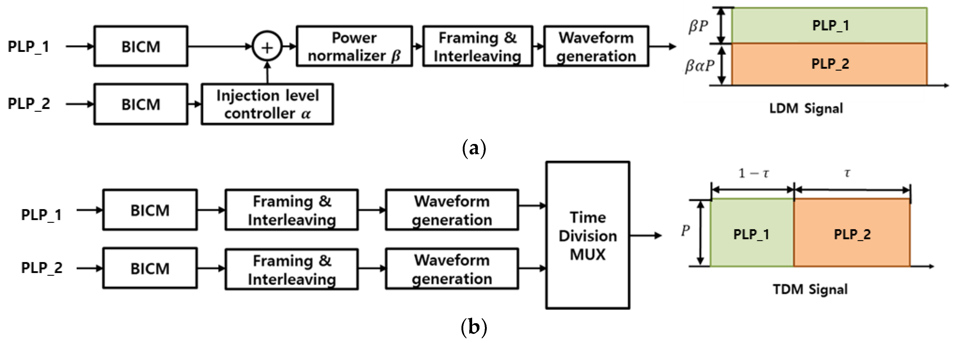
Figure 1 presents a block diagram illustrating the LDM and TDM systems utilizing two physical layer pipes (PLPs) [
16]. In the LDM system, the channel capacity is determined by adjusting the power ratio of each PLP through an injection level parameter
α, which scales the power level of the lower layer relative to the upper layer. Additionally, the power normalizing factor
β is multiplied by the combined LDM signal to maintain a constant total transmit power. In a TDM system, the channel capacity of each PLP is determined by the time ratio [
5].
In previous studies on LDM, the reception performance of each PLP was compared by setting specific injection levels and time ratios to achieve a similar data rates [
5,
17].
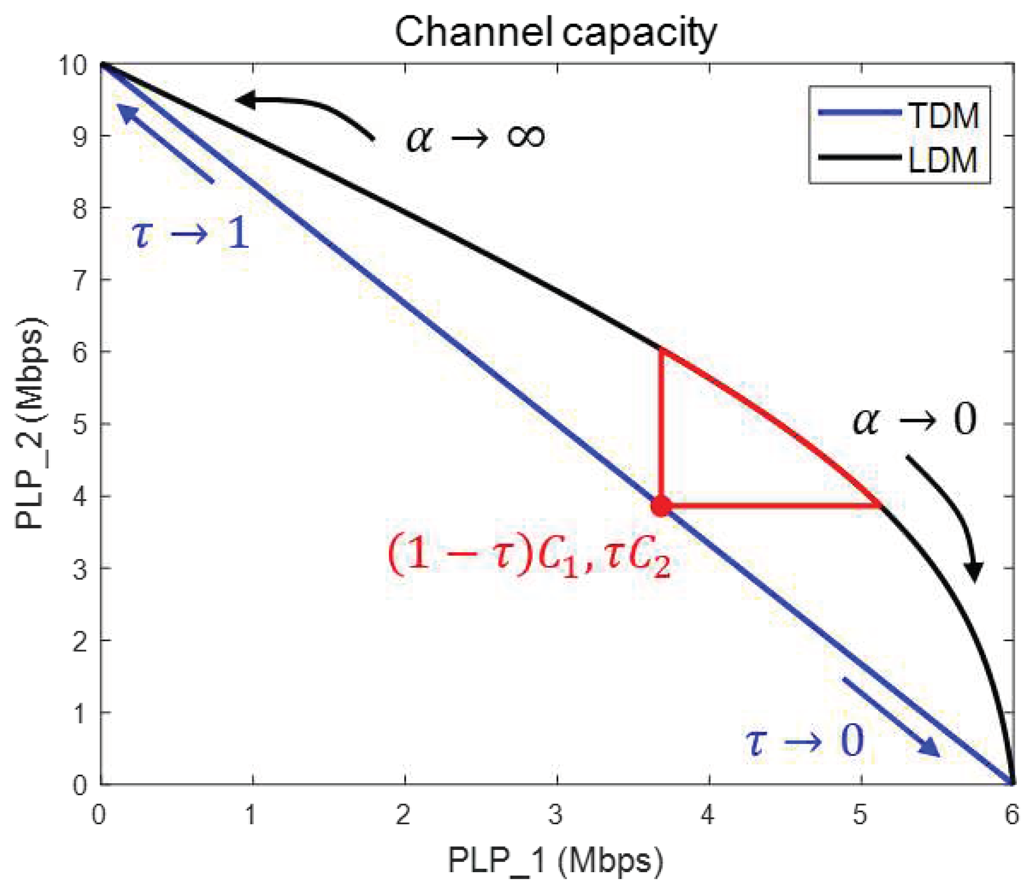
Figure 2 illustrates a comparison between the LDM system with an injection level α and the TDM system with a time ratio τ [
11]. The red-line area in the graph represents the LDM system, which exhibits better channel capacity for both PLP 1 and PLP 2 compared to the TDM system (indicated by the red dot) at a specific τ. However, it is not easy to determine which
α is the most efficient because the channel capacities of the two PLPs are different.
To compare the channel capacities of the TDM and LDM systems, the Shannon channel capacities
and
can be defined according to the target received signal-to-noise ratio (SNR) in each PLP [
11]. By utilizing the given SNR, the channel capacity of each PLP in the LDM system can be expressed as a function of
α. To find the optimal value of
α, the normalized channel capacities of the two PLPs are defined. Normalizing the channel capacity of each PLP allows for a fair comparison of system efficiencies, even with different parameters. The sum of the normalized channel capacities is used to determine the most favorable combination. Thus, the most efficient α value for the LDM system can be obtained by identifying the point where the sum is the maximized. By extension, studies have been conducted on the channel capacity of multi-PLP transmission schemes [
5,
16]. To provide various services such as UHD broadcasting services, mobile HD services, and breaking news in disaster situations, an efficient distribution of channel capacity is required for each PLP [
3,
4,
5,
6,
7]. Similar to the 2-PLP LDM system, the power ratio of each layer in the 3-PLP LDM system is determined according to two injection levels. The TDM system transmits using a time ratio divided by three from the total duration [
5,
16]. Additionally, there are layered-time division multiplexing (LTDM) and time-layered division multiplexing (TLDM) systems that combine TDM and LDM principles in a 3-PLP transmission scheme [
5].
The LDM system in ATSC 3.0 has different objectives compared to traditional NOMA systems. Traditional NOMA systems aim to maximize spectrum efficiency by allowing multiple users to share the same time and frequency resources. Therefore, the goal is to provide equal channel capacity to all users, considering fairness among them [
23,
24,
25,
26]. However, the LDM system in ATSC 3.0 aims to provide various services, such as emergency messaging, mobile communication, and fixed rooftop broadcasting, within limited time and frequency resources [
3,
4,
5,
6,
7]. The objective is to optimize the allocation of channel capacity among these services to offer a diverse range of services effectively. In LDM systems, where the channel capacity provided for each service is different, it may be difficult to apply the fairness and maximum sum rate used in NOMA performance analysis. In this article, we propose a method for analyzing the efficiency of the LDM system by normalizing the channel capacities allocated to each service. By normalizing the channel capacities, it becomes possible to evaluate the normalized fairness and the sum of normalized channel capacities. This approach allows for a fair comparison of the efficiencies and resource allocations among different services within the LDM system.
In a wireless transmission system, the channel capacity is affected by bandwidth and signal power [
20], which are assumed to be specifications of a transmission system. When comparing the multiplexing methods using the given specifications, we assume that the bandwidth and total signal power of each multiplexing are equal for a fair comparison. Specifically, the sum of the PLP powers in the LDM system is equal to the power of the TDM system. By setting this as a constraint, The Lagrange multiplier method [
18] can be used to obtain most efficient combination of
α, which represents the power allocation in the LDM system. The goal is to find the value of α that maximizes the sum of normalized channel capacities in the 3-PLP system. By utilizing the Lagrange multiplier method and comparing the normalized channel capacities, the channel capacity efficiency and reception performance of the TDM, LTDM, and TLDM systems can be analyzed and compared.
The remainder of this article is organized as follows:
Section 2 explains the structures of the LDM, TDM, LTDM, and TLDM used in a 3-PLP system.
Section 3 describes the problem of the fairness and performance measures of the LDM system.
Section 4 proposes a method to obtain the optimal normalized channel capacity using the Lagrange multiplier method.
Section 5 analyzes the efficiency of various transmission combinations of the 3-PLP system and compares the reception performance of each PLP using the parameters obtained using the Lagrange multiplier method. Finally,
Section 6 concludes the article.
3. Problem description
LDM shares time, space, and frequency resources to transmit various services, and its transmission method is similar to NOMA. However, there are differences between the two transmission methods in terms of purpose and application. While NOMA focuses on maximizing spectral efficiency with the goal of fair channel capacity allocation to all users, the LDM system aims to efficiently transmit multiple services simultaneously. In wireless communication systems, Jain’s Fairness Index (JFI) is commonly used as a measure for evaluating fairness [
23]. The JFI ranges from 0 to 1, where a value closer to 1 indicates a fairer allocation of resources. The JFI index is:
where
is number of users, and
is
i-th user data rate. In a NOMA system, research is conducted to allocate resources when the JFI is close to 1, ensuring fair distribution of channel capacity among users [
24]. However, in the case of LDM, the fairness index tends to decrease as the number of services varies because each service has a different target channel capacity. Since the objective of the LDM system is to efficiently transmit multiple services with varying requirements, the emphasis is on optimizing resource allocation to meet the specific needs of each service rather than achieving perfect fairness among them.
In NOMA, it is generally aimed to provide equal data rates to all users in a fair scenario, and the maximum sum rate is used as a performance measure [
23,
24,
25,
26]. However, in the LDM system, each service may have different data rate requirements, and simply using the maximum sum rate as a performance measure may not lead to an efficient allocation of resources among the services. In the given example of a 3-layer LDM system, the system considers three different types of transmission with their respective minimum data rate requirements:
Radio transmission ( ≥ 0.5 Mbps, QPSK, code rate: 3/15)
Mobile HD transmission ( ≥ 3 Mbps, QPSK, code rate: 6/15)
UHD broadcast ( ≥ 20 Mbps, 64-QAM, code rate: 9/15)
If the maximum sum rate is used as the performance measure in the 3-layer LDM system, the resource allocation will prioritize maximizing the data rate of the UHD broadcast service (). In the case of an LDM system, different constellations and code rates are used for each layer based on the specific service requirements. Therefore, if the goal is to achieve the maximum sum rate, the resource allocation strategy is to allocate as many resources as possible to D_3 having the highest transmission rate per unit sample. Allocating the majority of resources to D_3, which has the highest transmission rate, can lead to unfairness between services, particularly for D_1 and D_2, which only meet their minimum performance requirements. In the case of an LDM system where each service has different data rate requirements, simply maximizing the sum rate may not align with achieving fairness among the services.
To address the fairness issue, we propose the utilization of normalized channel capacities as a solution. By normalizing the channel capacities provided to each service, the authors aim to establish a fair comparison measure. The normalized channel capacities can be used to evaluate the fairness among services, similar to the approach used in NOMA. Furthermore, the authors suggest maximizing the sum of normalized channel capacities as a performance measure for the LDM system. By maximizing this value, the system aims to achieve an optimal allocation of resources that balances efficiency and fairness. This approach resembles the objective of maximizing the sum rate in NOMA and leads to maximizing the overall system performance while ensuring fairness among users.
The maximum channel capacity of PLP_i is the Shannon channel capacity [
19] when PLP_i is used alone and can be expressed as follows:
Then, the normalized channel capacity of each system is defined as follows:
where
denotes the channel capacity of PLP_i in M system, which is one of the four multiplexing systems (TDM, LDM, LTDM, and TLDM). The normalized channel capacity provides a measure of the efficiency of each PLP in the different multiplexing systems. We present a system that achieves the highest overall efficiency by maximizing the sum of normalized channel capacities for all PLPs. This approach helps in determining the most efficient multiplexing system among the four options (TDM, LDM, LTDM, and TLDM) based on the considered PLPs.
4. Proposed method for Lagrange multiplier method
In this section, we attempt to determine the optimal channel capacity in an LDM system using a Lagrange multiplier. The Lagrange multiplier method is commonly employed to determine the optimal solution under constrained conditions [
18]. In the example shown in
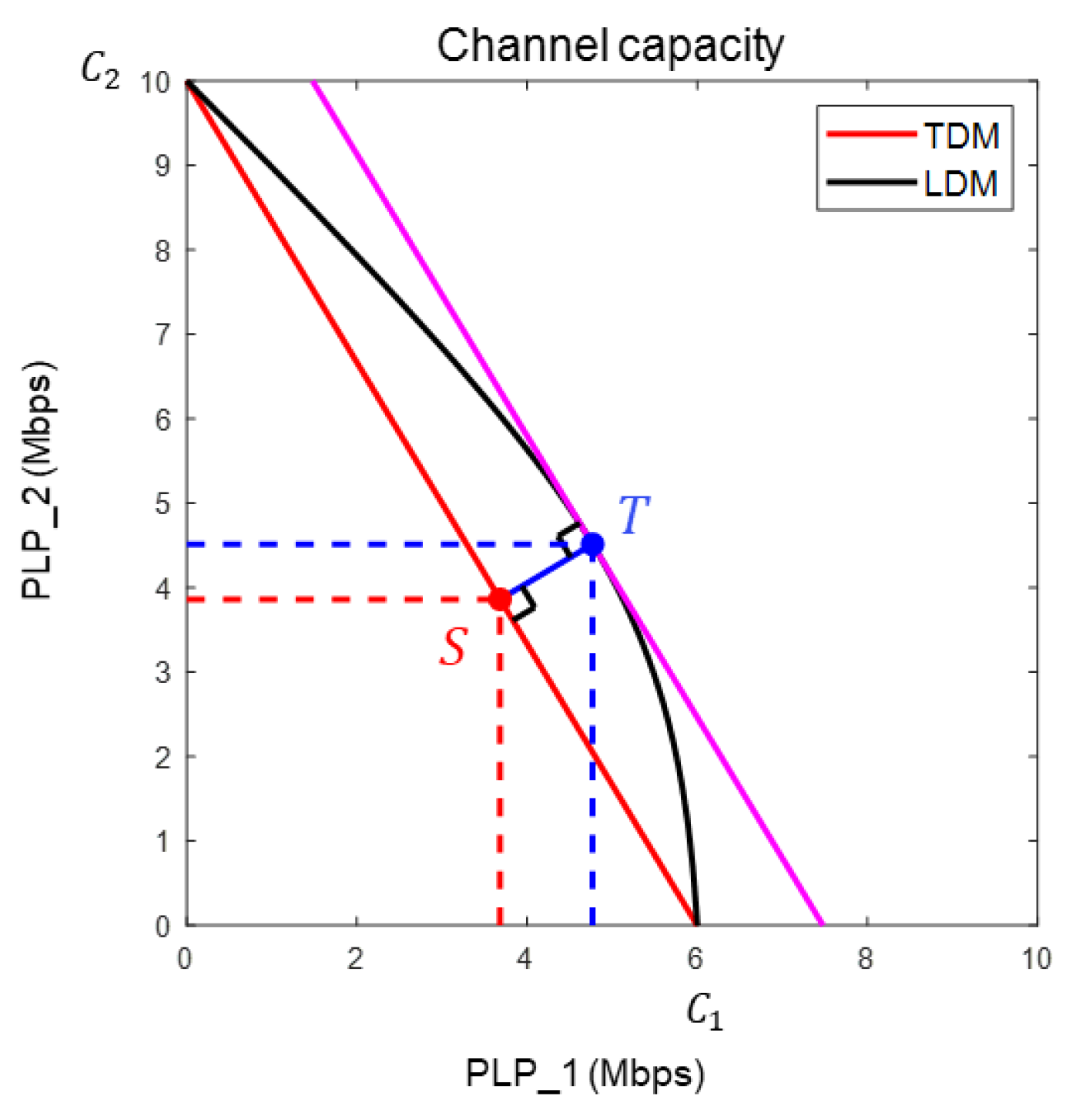
Figure 7, the largest value of the sum of the channel capacities is 10 Mbps when only PLP_2 is used without the PLP_1 service. However, if the two services must be provided simultaneously, some portions should be allocated to the PLP_1. In the case of LDM, where each PLP may have different channel capacity requirements, it is important to find an optimal solution that can efficiently utilize the system’s resources. To achieve this, the article proposes the use of normalized channel capacity.
Mbps, Mbps).
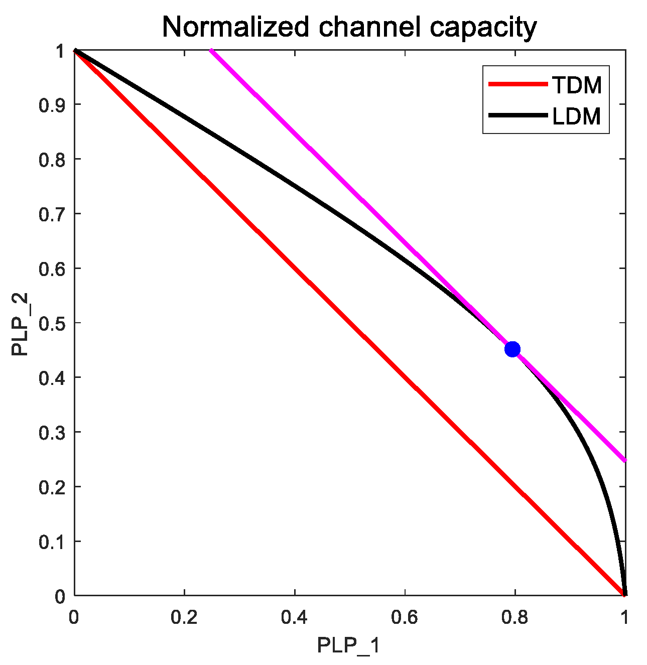
Figure 8 shows the normalized channel capacity of each PLP, as shown in
Figure 7. In the 2-PLP LDM system shown in
Figure 8, we can find the point where the sum of the normalized channel capacities is at its maximum. To obtain the maximum sum geometrically, it is necessary to determine the position where
is maximized in the linear function of
. In the 2-PLP LDM system, the point where k is maximum is
, which is a tangent point to the magenta line with a slope of -1.
is the normalized position of point T in
Figure 7, and point
is the maximum sum of the normalized channel capacities in the 2-PLP LDM system.
Point
can be determined analytically using the Lagrange multiplier method. Extending to the 3-PLP LDM system, point
in
Figure 9 is the optimal solution, where the sum of the normalized channel capacities of the three PLPs reaches a maximum. The following subsections describe the method by which the
point can be obtained using the Lagrange multiplier method for the three PLPs.
4.1. Lagrange method in the 3-PLP LDM system
The LDM system using the three PLPs are as follows:
Initial channel capacity ;
(total power of 3-PLP TDM = total power of 3-PLP LDM);
PLP_i has the same additive noise in TDM and LDM;
Same bandwidth of 3-PLP TDM and 3-PLP LDM system;
(successive interference cancellation, SIC [
24])
If the above conditions are satisfied, the channel capacities of the LDM and TDM systems can be configurated as in
Figure 9, when three PLPs are used. The channel capacity of a TDM system is represented by the green plane and that of an LDM system is represented by a black spherical area. To find the optimal point of T, W and P values are assumed not to affect the calculation result, so W=1 and P=1 are used. Substituting
and
the Equations (2)-(4) can be rearranged as follows:
Using the constraints and equations organized as above, the Lagrangian function can be expressed as follows: [
18]
where
is the Lagrange multiplier. The Lagrange multiplier method can obtain a simultaneous equation by assuming that
is 0 [
18], then the simultaneous equation is as follows:
Using Equations (18)-(21),
,
and
can be derived using the following equations:
Substituting the calculated , and into Equations (2)-(4), the channel capacity of an LDM system with maximum efficiency can be obtained.
For a comparison with the LDM system, we will explain how to obtain the S point of the TDM system closest to point T in
Figure 9. To determine S, we derived the equation of a straight line through T, which is parallel to the normal vector of the TDM channel capacity plane (green plane). The straight-line equation and equation of the green plane are expressed as
respectively. The solutions to the two equations are located at point S. Because the coordinate point of S is [
],
of the TDM system can be derived as a result of the simultaneous equations (25) and (26), and we obtain the following equations:
The method for obtaining the optimal parameters using the Lagrange multiplier method is summarized as follows:
Select the initial values of , and .
Calculate the noise corresponding to , and .
Derive, and using the Lagrangian function.
Calculate the LDM’s channel capacity using , and .
Find the point S by deriving the equation of the straight line and the equation of the plane and solving these simultaneous equations.
Calculate , , and from the coordinate point S.
4.2. Lagrange method in the 3-PLP LTDM and TLDM systems
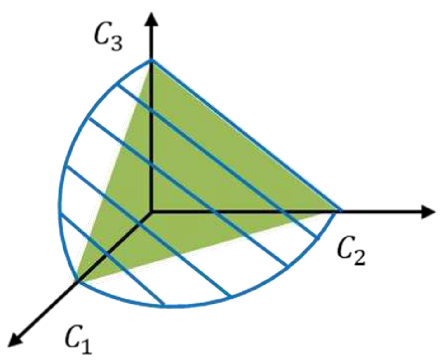
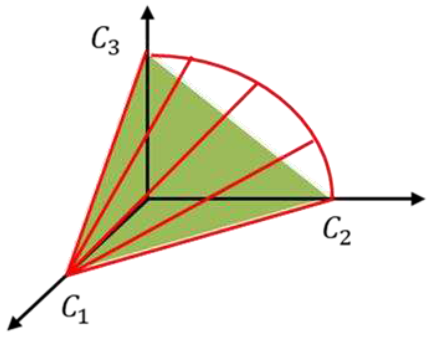
Figure 10 and
Figure 11 show the channel capacities of an LTDM system (blue area) and a TLDM system (red area). The point where both systems have an optimal solution is when
and
are equal to zero, that is, when used like a 2-PLP LDM system. To compare the situation using three PLPs, we added a condition that
and
are equal to
of the TDM system obtained from Equation (26). The initial conditions for obtaining the optimal
and
of the LTDM and the TLDM systems are as follows:
Initial channel capacity .
(total power of the 3-PLP TDM = total power of the 3-PLP LTDM and 3-PLP TLDM).
PLP_i has the same additive noise in two systems.
Same bandwidth of 3-PLP TDM, 3-PLP LTDM and 3-PLP TLDM system.
(successive interference cancellation, SIC [
24])
To find the
in the TLDM system, assuming W=1 and P=1, and substituting
and
Equations (9) and (10) are rearranged as follows:
Using the constraints and equations organized as above, the Lagrangian function is given by [
18] the following equation:
The system of equations using the Lagrange multiplier method is computed as follows: [
18]
Using Equations (31)-(33),
and
can be derived as follows:
By substituting the calculated and into Equations (8)-(10), the channel capacity of the TLDM system with the maximum efficiency can be obtained when .
For the LTDM system, if the Lagrange multiplier method is applied in the same way using Equation (5) (PLP_1) and Equation (7) (PLP_3), the channel capacity of the LTDM system with the maximum efficiency can be obtained when
. The LTDM parameters calculated by applying the Lagrange multiplier method using Equations (5) and (7) are as follows:
5. Simulation result
In this section, the channel capacity analysis results of the four multiplexing systems are presented using the parameters calculated by the Lagrange multiplier method when the three PLPs are operated. The efficiency of each system was compared in terms of the normalized channel capacity . The required SNR values for achieving the target bit error rate (BER) are also presented. The modulation and code rate (ModCod) of the transmitted signal follow the specifications outlined in the physical layer of ATSC 3.0. It is assumed that perfect channel state information is available and there are no synchronization errors.
To evaluate the fairness of the system, we can calculate the normalized fairness index (NFI) using the normalized channel capacity. The NFI provides a measure of fairness in resource allocation among the different services in an LDM system. The formula to calculate the NFI in 3-PLPs is as follows:
To determine the sum of the normalized channel capacities, we derived the parameters using the Lagrange multiplier method and calculated the corresponding parameter values based on
given in [
5]. These two parameter groups are listed in
Table 1.
and
can be calculated using the parameters listed in
Table 1, and the sum of the normalized channel capacities is defined as follows:
Table 2 shows the calculated results for
,
,
, and
which are used to evaluate the performance of different multiplexing systems. The results demonstrate that the sum of the normalized channel capacities obtained using the Lagrange multiplier method is higher than the comparison parameters provided in reference [
5]. For the TDM system, since the channel capacity
changes linearly according to
, the normalized channel capacity
is equal to
. In other words,
for any
. Therefore, if
is calculated using the Lagrange multiplier method or the comparison parameters provided in [
5], the result is the same. For other multiplexed systems, however, the channel capacities do not change linearly with the injection levels, unlike in the TDM system. Therefore, the sum of the normalized channel capacities differed depending on the injection level. For an LDM system, the sum of the normalized channel capacities of the Lagrange multiplier is 0.08 greater than that mentioned in [
5]. This implies the channel efficiency improved by 8%. Likewise, the Lagrange multiplier method can achieve 15% and 8% better performances in the LTDM and TLDM systems, respectively. By comparing the four multiplexing systems, we found that the LDM system was the most efficient. In terms of the sum of normalized channel capacities derived using the Lagrange multiplier method, the LDM system was 49% more efficient than the TDM system. The LTDM and TLDM systems were 38% and 24% more efficient than the TDM system, respectively. Furthermore, when resource allocation is carried out using the Lagrange multiplier method, it can be observed that the LDM system achieves the highest fairness index than other transmission methods. Through this analysis, it can be confirmed that the LDM system utilizing the Lagrange multiplier method achieves the highest sum of normalized channel capacities even under fair conditions.
Table 3 lists the
obtained using ModCod supported by the physical layer of ATSC 3.0, and the parameters obtained using the Lagrange multiplier method.
was calculated by substituting the required SNR at BER = 10
-4 obtained from the simulation into Equation (11). Using the parameters listed in
Table 3, we calculated the values of
,
, and
, as listed in
Table 4. Unfortunately, it is difficult to find a ModCod supported by ATSC 3.0, which has the same channel capacity as
obtained using the Lagrange multiplier method. Therefore, the required SNR was analyzed by setting ModCod such that it has a similar the performance of
.
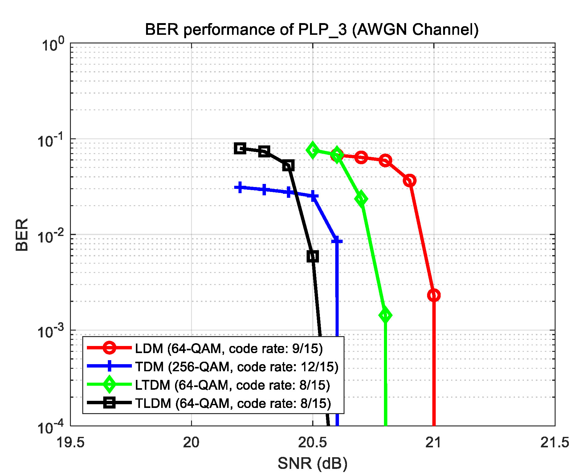
Figure 12 shows the BER performance of PLP_3 under an additive white Gaussian noise (AWGN) channel using the ModCod, which has the closest value to
listed in
Table 4. For example, the LDM system uses 64-QAM with a code rate of 9/15, and it can be confirmed that the required SNR is 21.1 dB, which is close to the
= 20.7 dB listed in
Table 3. In this way, for all cases, we searched for the ModCods closest to
, as listed in
Table 5.
Table 6 lists the required SNR at BER = 10-4 through simulations in the AWGN and fading channels, and the data rate, which is calculated using the following equation:
where
represents the guard interval time,
is the time ratio of i-th PLP of each system, and
is the number of bits per symbol used for modulation. In the case of PLP_1 and PLP_2, the TU-6 channel [
21] was used as the fading channel, considering a mobile reception of 100 km/h. For PLP_3, the RL20 channel [
22] was used, considering a fixed UHD service.
In the case of PLP 1, although the data rates of the LTDM and LDM systems were the same, the LTDM system was superior to the LDM system in terms of the required SNR performance under the fading channel by approximately 0.7 dB. In the case of PLP 2, the data rate of the TLDM system was the highest, as listed in
Table 2. In the case of PLP_3, the data rates of the LDM and TDM systems were similar; however, there was a 1 dB difference in the required SNR in the fading channel.
6. Conclusion
We proposed a method that utilizes the Lagrange multiplier approach to maximize channel efficiency in a three-PLP operation. We introduced the concept of normalized channel capacity as a measure for channel efficiency and computed the sum of normalized channel capacities. NFI was used to check fairness between services. When the system’s frequency, time, and power resources are provided, the system that can operate the three PLPs most efficiently is represented as the sum of the normalized channel capacities. For the TDM system, we confirmed that the channel efficiency was the same when using any . In other multiplexing systems, the results derived using the Lagrange multiplier method exhibited good channel efficiency. Among the four systems tested, the LDM system was the most efficient. In addition, when resource allocation is performed using the Lagrange multiplier method, it confirmed that the LDM system achieves the highest fairness index among the four tested systems.
Although the simulation experiment used the ATSC 3.0 system with three PLPs as an example, it can be applied to a transmission system that provides various services and multiple PLPs in the future. This method is expected to be useful for performance analysis in terms of system efficiency.
