1. Introduction
Concentrator photovoltaic (CPV) systems were presented as a promising renewable energy alternative [
1] to conventional photovoltaic (PV) systems. This technology is characterized by being able to concentrate sunlight on small but highly efficient photovoltaic cells [
2]. Although these high efficiency cells are expensive, their use is compensated by the low cost of the concentrator optical elements used in the system design [
3].
CPV technology mainly captures direct normal irradiance (DNI) from the sun. Because of this, the modules must be correctly oriented with respect to the incident sunlight. The need for greater precision in module orientation depends on its concentration ratio, i.e., number of times sunlight is concentrated. CPV is classified as Low (<10 suns), Medium (10-100 suns), High (100-2000 suns) and Ultra-High (>2000 suns) [
4]. At higher concentration, systems become more susceptible to misalignment errors, and accuracy becomes more necessary.
Conventional CPV systems require precise alignment and normal incident radiation at the module input. This is usually achieved by an external solar tracker that follows the movement of the sun [
5]. However, solar trackers represent an additional cost for both assembly and annual maintenance, making them a necessary but costly element of CPV technology. Although CPV has achieved record efficiencies such as the laboratory efficiency of 41.4% achieving by a high CPV module [
6], and a commercial efficiency of 34% [
7], its economic viability is affected by high installation and operating costs of the trackers. As a result, CPV is often considered to be economically uncompetitive with conventional PV systems [
8]. In addition to increasing the costs, the use of solar trackers further exacerbates this problem, as their weight and size limit their installation in certain locations.
In recent years, the research community has made a great effort to try to make CPV technology competitive, trying to introduce it into markets where traditional CPV had been excluded until now. To overcome this problem, the concept of tracking-integrated CPV systems has been developed. This type of tracking makes it possible to dispense with traditional solar trackers, taking advantage of other locations, such us the roofs of buildings [
9,
10], and even implementing it in applications in the field of Agrivoltaics (APV) [
11].
This paper presents a review of the different approaches developed on tracking-integrated systems.
Section 2 provides an overview of both traditional and tracking-integrated CPV systems, focusing mainly on tracking-integrated within the module itself.
Section 3 presents the summary and conclusions derived from the study.
2. Overview of CPV tracking systems
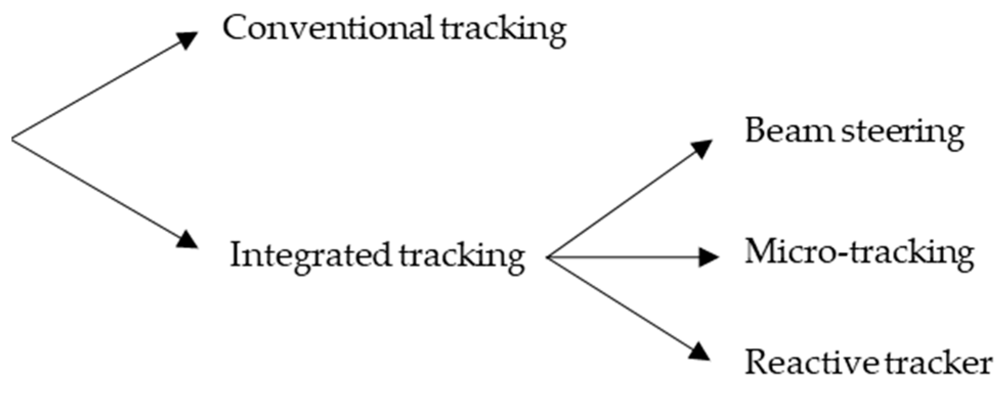
CPV systems mainly capture solar radiation through direct sunlight. Keeping the modules properly oriented is therefore necessary. To accomplish this, solar trackers are used to track the daily and annual position variation of the sun. Several types of solar trackers have been developed, and they can be classified based on the tracking process as either external or internal to the concentration module. A basic classification of systems with tracking-integrated has been proposed by Apostoleris et al. [
12] (see
Figure 1).
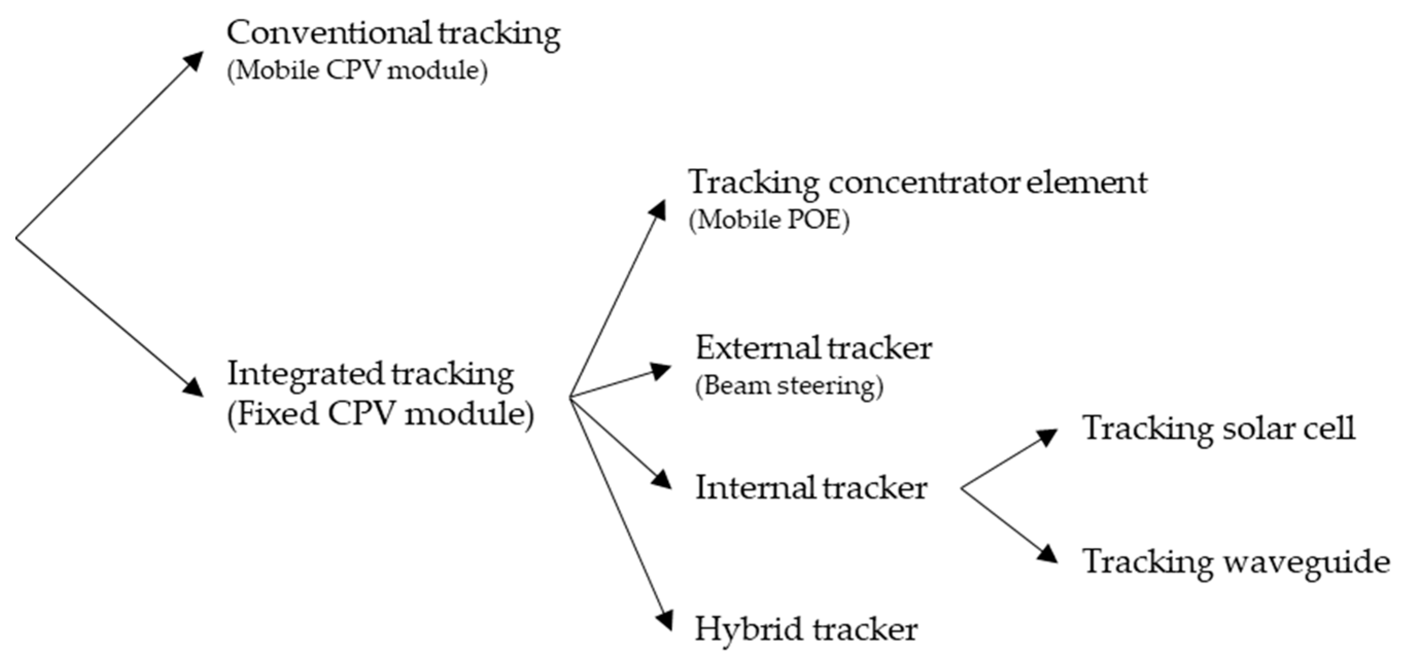
In this work, a complete classification of the different CPV tracking systems is proposed (see
Figure 2). These solar trackers have been classified according to where the tracking takes place and the specific devices involved.
Moreover, a more general classification divides the solar tracking systems into conventional trackers, and integrated trackers. Within each category, the type of tracking that takes place is specified in more detail.
2.1. Conventional tracking
The conventional tracking make use of a mechanical structure, an additional external element on which the CPV module is placed, in order to follow the daily and/or annual movement of the sun. These devices are divided into two groups, single or two-axis trackers [
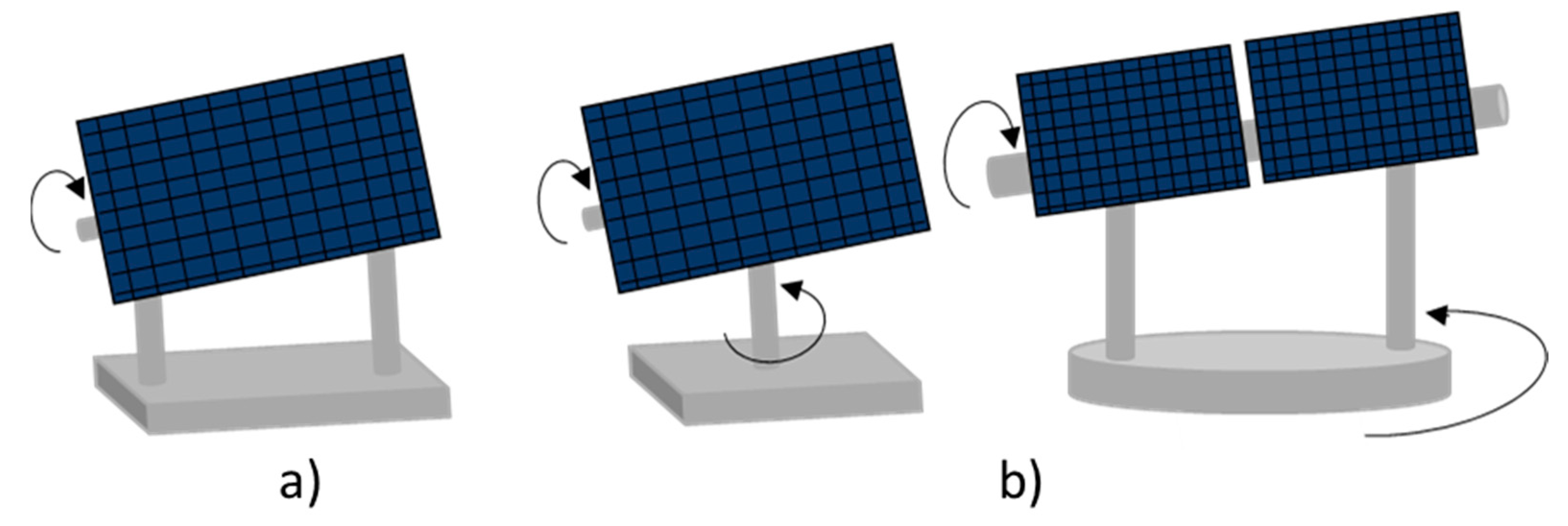
4], depending on whether they move in one or two directions. From the above division according to the concentration ratio, low CPV and medium CVP systems use single-axis systems, such as horizontal or inclined-axis trackers. These types of tracker allow higher levels of incident irradiance, although they do not keep the CPV modules perpendicular to the direct beam at all times. For a higher level of concentration, CPV systems are more sensitive to misalignments. In this case, two-axis solar trackers such as the Pedestal-mounted, Carousel and Tilt-and-Roll, are used to achieve greater daily and seasonal adjustment. A design of some of these types of solar trackers can be seen in
Figure 3.
2.2. Integrated tracking
Incorporating tracking mechanisms into a CPV module provides a distinctive approach for aligning the system with the trajectory of the sun. Rather than relying on conventional tracking devices, the CPV module itself can perform the task by automatically adjusting its components to the movement of sunlight. In this scenario, the concentrator module maintains a fixed inclination while the mobile components enable it to sweep through a specific range of angles of incidence (AOI) as the sun moves across the sky. This innovative approach has been investigated in numerous research publications, and the objective of this article is to further explore this concept. Tracking can be accomplished through various methods: external tracker, tracking of the concentrator elements, internal tracker or hybrid tracking. Each of these tracking systems is discussed below.
2.2.1. Tracking concentrator elements
As a first case, the idea of tracking using the primary optics that is part of the CPV system is presented. Thus, the Primary Optical Element (POE) [
13] becomes the moving component, or one that can changes its internal properties, with the motion of the sun.
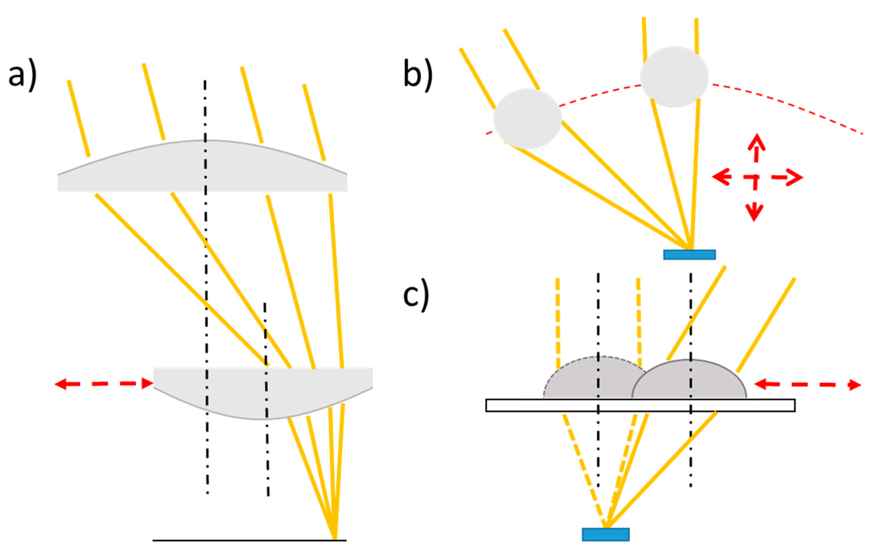
Refractive elements are mainly the components used for a basic CPV system design and by means of mechanical displacement of the lens, mobile optics are achieved. One option to achieve tracking and focus the incident beam onto the solar cell is through the combination of two plano-convex lenses, and by lateral translation of both elements [
14]. However, achieving free-form optic instead of a simple preset geometry would improve the performance of the system with a concentration greater than 500x on which monochromatic light is incident, while maintaining the full field of view (±24
o) [
15]. Considering the full solar spectrum, the concentration ratio will be considerably lower due to scattering. This problem can be solved by including an additional concentrator on the top of the solar cell [
16,
17], thus achieving a more uniform radiation distribution over the solar cell surface [
18,
19,
20].
By replacing the primary concentrator with a GRIN (GRadient-INdex) spherical lens [
21], the system is able to capture radiation within an AOI range of ±60
o while maintaining high-concentration levels. There is a lateral and vertical shift to the POE, describing a curve in its trajectory. The use of this type of concentrator optic reduces losses due to dispersion compared to a conventional lens, along with only 1-2% losses due to alignment issues.
Tsou et al. employ a different concentrator than the typical solid lens. They employ a liquid lens (LC) that, by placing it on the surface with electrodes, focuses light on the solar cell as the AOI changes [
22]. Activating the electrodes that form the system causes a deformation or movement of the LC in the direction of the activated electrode, with a maximum AOI of ±25
o.
Represented in
Figure 4 are the various tracking-integrated systems commented above, where the tracking element is the POE.
2.2.2. External tracker
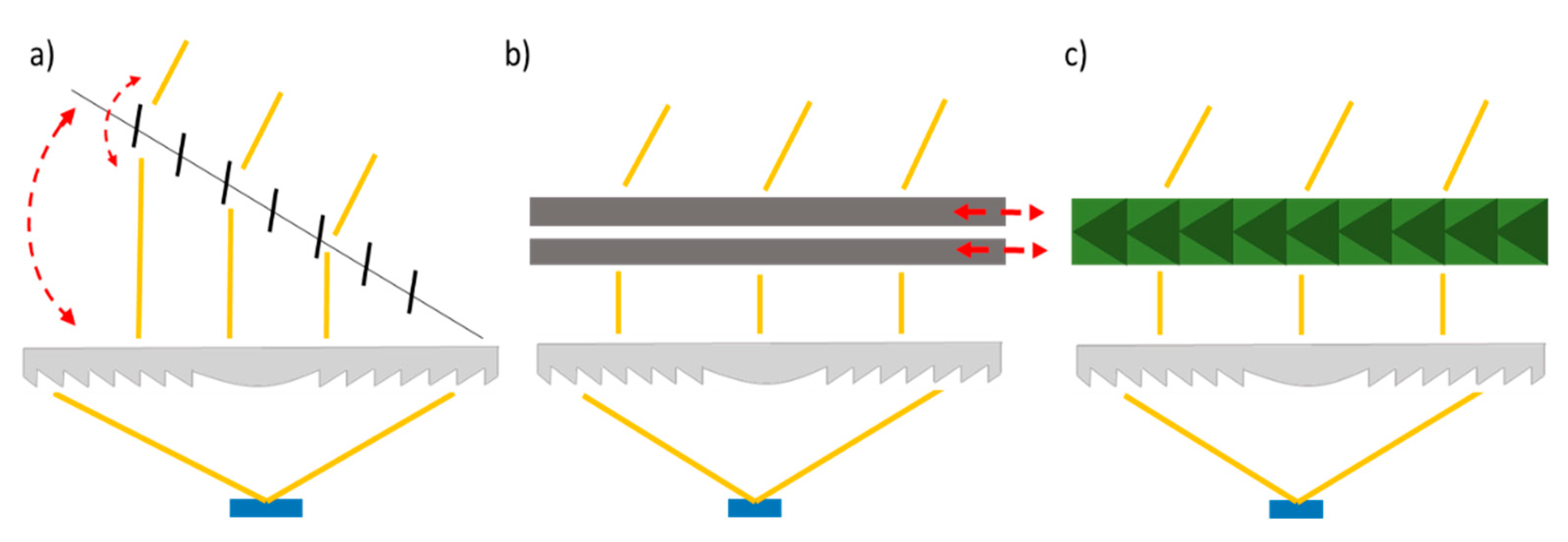
By keeping the POE fixed, tracking can be carried out before concentration takes place. In this type of design, the basic CPV module (consisting of the POE and the solar cell) has an additional external component attached to it that performs solar tracking.
Since the basic CPV system is maintained in a horizontal position relative to the ground, the objective of the external trackers is to collimate the incident light beam reaching the surface of the POE at an AOI different from the normal incidence. In this way, direct radiation incident with any AOI within the tracking range is redirected and collimated towards the surface of the POE. This type of tracking utilizes a concept known as beam steering [
23,
24]. Several studies have explored the use of mechanical movements using mirrors, prisms or even beam-steering lens arrays (BSLA) to achieve this goal [
25,
26,
27,
28,
29,
30]. Alternatively, and with the same purpose of collimating the beam, some systems make use of prism-shaped liquid crystals [
23,
31,
32] to change the angle formed between two immiscible liquids with different refractive index, instead of resorting to mechanical displacements. The latter can be electrically modified or controlled via electro-wetting to change the angle formed between the two materials.
Figure 5 illustrates a schematic representation of some of these systems.
2.2.3. Internal tracker
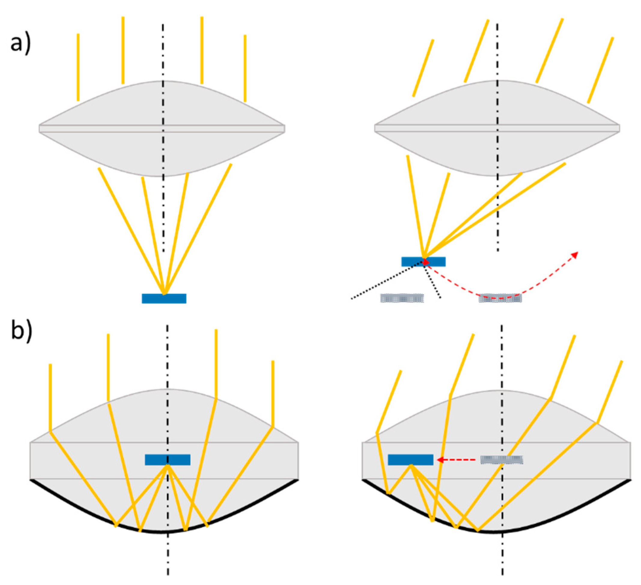
As an alternative to the external tracker, and once the radiation passes through the POE, an internal tracker can be employed. In this way, solar tracking takes place after beam concentration by the static POE By using point-focus lenses, the variation of the AOI of sunlight on the surface of the concentrator element causes the radiation to focus on a different location. Changing the AOI shifts the focal point of the POE to a new position. In this case, tracking is performed after the concentrator elements, and can be carried out by the solar cell itself or by an additional optic, such as waveguide, that direct the radiation towards the solar cell.
2.2.3.1. Tracking solar cell
The simplest tracking-integrated system consists of the concentrator optics and the moving cell. Using a convergent lens as POE, as the incident beam changes its inclination, the spot generated by the convergence of the beams changes its position. This new location leads to a lateral displacement, and a decrease in the focal length of the lens. As can be seen in
Figure 6, the motion describes by the spot has a curved shape, a displacement known as Petzval curvature [
33]. If the receiver only moves laterally, as AOI increases, part of the concentrated radiation falls outside the cell (see
Figure 6) and will not be collected by the cell. It is necessary for the cell to move both horizontally and vertically, so as to be located at the focal point of the lens at any time [
34]. Tracking can be done using an automated dual-axis planar solar tracker [
35]. Despite the moment in two directions to compensate for the focal shift, conventional convergent lenses, e.g. the Fresnel lens, are not a good choice in these systems. In addition to surface curvature, there is the problem of spherical aberration in these optical elements. This aberration is more noticeable the higher the AOI. Therefore, their tracking range is limited to a few degrees. Research has succeeded in resolving this aberration by using bi-convex aspheric lenses [
36]. Using this type of optics, it is possible to measure an AOI range of up to ±50
o with an optical efficiency (η
opt) higher than 70% within that range [
37]. A schematic of this type of configuration can be seen in
Figure 6. Insolight has developed a hybrid micro-CPV module with bi-aspheric lenses. It is a hybrid system with multi-junction cells placed on a silicon panel, thus capturing both direct and diffuse radiation. A first evaluation of this prototype has been measured at the Solar Energy Institute of the Polytechnic University of Madrid (UPM-IES) [
38,
39].
To avoid double displacement of the receiver, an alternative design is presented. This is a system consisting of two arrays of lenses, the first plano-convex and the second plano-concave, between which a flat transparent surface is inserted as in a sandwich configuration. The first lens array realizes a first convergence of the incident radiation towards the surface of the second lens array. This surface is coated with a reflective material in charge of reflecting the beam onto its focal point. This reflected radiation is concentrated on the transparent surface, located at the focal point of the reflector. The GaAs solar cell used is place on this transparent surface, moving only with lateral movements to follow the spot [
40], thus eliminating the Petzval curvature (see
Figure 6). With this configuration (geometrical concentration (C
g) = 225x), it is possible to measure an η
opt higher than 79% for an AOI range of ±60º. A further study of this design achieves a effective concentration (C
eff) > 660 in a field of view of ±70º, exceeding 30% maximum energy conversion efficiency, with losses of 5% due to cell heating [
41].
2.2.3.2. Tracking waveguide
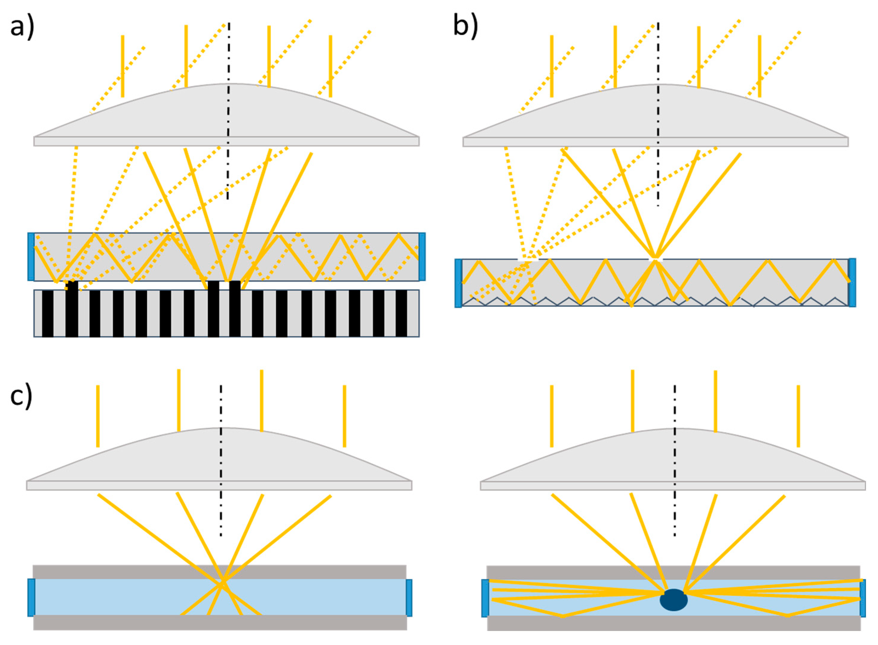
By incorporating an additional optical element to the CPV system, such as a waveguide, the distribution of radiation on the photovoltaic cell becomes uniform. The light guide is now the device in charge of tracking the movement of the focal point. The tracking can be mechanical, by means of a lateral displacement of the guide as the AOI varies throughout the day [
42], as can be seen in
Figure 7. It moves as much as 1.6mm for angles of ±30º, although high efficiencies are limited to ±10º [
43]. The lateral shift to follow the daily movement of the sun can be accompanied by a seasonal adjustment (±23.5º). This is done by an additional lateral shift of a lens array of the two pairs that are part of the radiation concentrator system [
44]. Although the average transmission of the study is 90.7%, this system, with a concentration ratio of 500x, is more complex due to the double translation.
The mechanical tracking of the light guide can be suppressed by a different tracking concept. To achieve this, the characteristic response of the materials forming the waveguide is used. Baker et al. [
45] first presented this type of tracking, known as reactive tracking or self-tracking systems.
Exploiting the phase change properties of materials is one way to achieve this. A polydimethylsiloxane (PDMS) membrane placed under the waveguide is included in the design of a CPV system. This membrane contains within it a prism-shaped dichroic structure [
46], and the material of which it is composed, sets a wavelength limit value of the concentrated radiation. Wavelengths shorter than this limit are reflected, while for longer wavelengths, the radiation is absorbed. This absorption increases the temperature, generating a phase change in the material and increasing its volume. The increase in volume pushes the membrane over the waveguide, causing the reflected radiation to couple to it, and driving it into the cell located at the edge of the waveguide. An acceptance angle of ±16º is achieved for a C
g of 280x, with a simulated effective concentration of 8x versus 3.5x measured, with an efficiency of 2.8% [
47].
Figure 8 a) shows a diagram of this integrated tracking system.
Another way of tracking the movement of the focus is carried out with a light guide wrapped with a passive top coating and a smart bottom coating [
48]. As the radiation is concentrated on one point, the tension between the layers is reduced, due to the increased temperature. This opens an optical path to reflective surface just below the array, reflecting the radiation into the waveguide where it is trapped and travels through it to the photovoltaic cell. With this configuration, the researchers have achieved η
opt of up to 72% and self-tracking at angle of up to ±25º.
Replacing these coatings with a switchable transparency layer on the top surface of the waveguide [
49] follows the variation of the AOI. This fully opaque material becomes locally transparent when concentrated radiation is incident on it (see
Figure 8 b). When this happens, the rays reach the waveguide, and are reflected until they reach the solar cell. In the ideal case, a capture efficiency of 25.7% is obtained. Another type of secondary optics such as a compound parabolic concentrator (CPC) [
50] covered with the same switchable material [
51,
52] is investigated, instead of employing light guides. Theoretically, a η
opt of 95% is achieved with an angular range of ±23º and an approximate concentration of 31 suns.
Although the waveguide is normally solid, a self-tracking system with a liquid guide is found in the literature [
53,
54]. Composed of methanol, it is enveloped by a glass top layer and an IR absorber on the bottom. This absorber causes the infrared part of the concentrated solar spectrum to be exploited to realize the self-tracking mechanism. The absorption of this part of the beam provides the energy necessary for the generation of vapor bubbles in the waveguide. The remaining radiation focused on the bubble is then reflected by the total internal reflection at the liquid-gas interface, to couple to the guide, and travel to the receiver.
Figure 8 c) below shows this type of self-tracking.
2.2.4. Hybrid tracking system
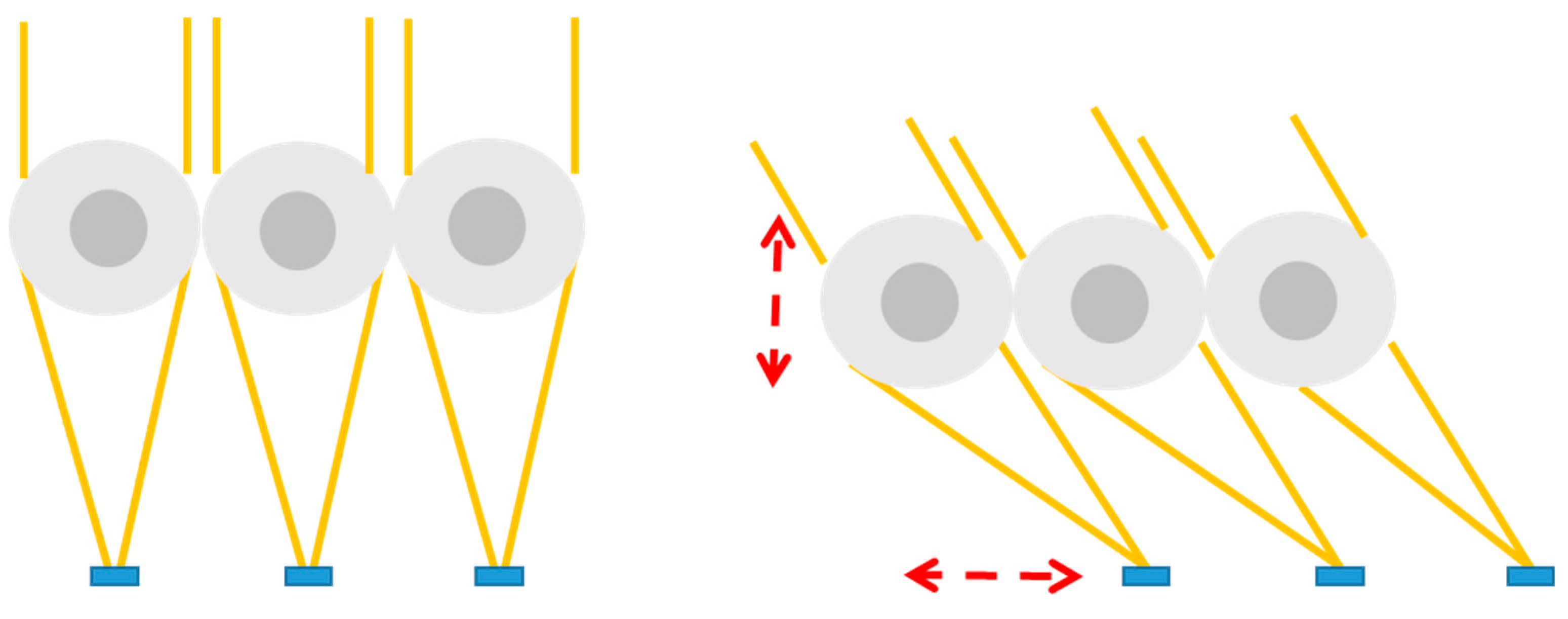
Mainly, the literature on tracking-integrated systems primarily addresses single-stage tracking, wherein tacking takes place at a specific moment and is executed by one of the elements of the module As shown earlier, this occurs either through the primary optics or, depending on whether it is an external or internal tracker with respect to the POE. However, a special case of two-stage tracking is also encountered. It involves a two-shell spherical lens array, each layer with a different refractive index, along with a solar cell. In this design, the lenses move vertically while the cells move laterally. Solar radiation is concentrated within a maximum incidence angular range of ±44
o [
55]. In addition, the simulated η
opt achieved is 76% for a system with a C
g of 100x. A schematic of this system is presented in
Figure 9.
2.3. Summary of integrated tracking literature review
Once an accurate review of the existing literature on tracking-integrated systems has been carried out, the main characteristics of each design are compiled in
Table 1. This table presents a summary of the results obtained from the analyzed articles. The “Ref” column includes the bibliographic references of each article to facilitate further consultation. The “n
o of movements” column indicates whether a single-direction (x1) or dual-direction (x2) movement is required to achieve solar tracking. This information is crucial for understanding the complexity and practical viability of the examined tracking-integrated systems.
The “no of mobile elements” column highlights whether a single component (1) or two component (2) are used for tracking, providing essential insights into the configuration and design of CPV systems. Additionally, the “Mobile element” column specifies the type of component used, such us a lens, a solar cell, a waveguide, or any other specific element responsible for carrying out the tracking.
The “Control” column describes the method employed to control the movements of the tracking system, which may include mechanical approaches, changes in material properties, or any other relevant control mechanism investigated in the reviewed studies. The “Tracking-integrated” column provides information on whether solar tracking occurs before concentration, or once concentration has taken place. Finally, the “Other data” column indicates whether the analyzed studies are of a theoretical nature or also include experimental aspects, enabling us to understand the scope and limitations of the findings presented in the reviewed articles.
In summary, the compilation and presentation of the summarized information in
Table 1 provide an overview of the key features and identified variation in the studied solar tracking systems. This data synthesis forms a solid foundation for the analysis and detailed discussion of the results, facilitating the identification of emerging trends and evaluation of implications for the design and optimization of CPV systems.
3. Conclusions
In conclusion, this comprehensive review provides valuable insight into the research and technologies of CPV tracking-integrated systems. The expanded classification of sunlight tracking methods presented here offers a deeper understanding of the different ways investigated to integrate tracking into the CPV module. Furthermore, the use of different material emerges as a crucial factor for improving current systems and inspiring future innovative designs.
The potential of tracking-integrated CPV systems to expand into previously untapped markets is significant. By enabling the deployment of CPV in areas where conventional CPV solar trackers is not feasible, such as on building rooftops or in agricultural applications, this technology holds promise for broader adoption and increased energy production. Future studies focusing on designs optimization, manufacturing cost analysis and energy production will be essential to realize fully the potential of this type of technology and its impact on CPV industry.
Author Contributions
M.A.C.: Conceptualization, methodology, validation, investigation, data curation, writing—original draft preparation, writing—review and editing. P.J.P-H: Investigation, methodology, supervision, writing-review and editing, funding acquisition. E.F.F.: Supervision, writing-review and editing, funding acquisition. F.A.: Supervision, writing-review and editing, funding acquisition. All authors have read and agreed to the published version of the manuscript.
Funding
This work is part of the project WiT – CPV funded by the Spanish Ministry of Science and Innovation – Agencia Estatal de Investigación (AEI – CNS2022-135288).
Data Availability Statement
Not applicable.
Acknowledgments
María A. Ceballos is supported by the university of Jaen under the program “Ayudas predoctorales para la Formación de Personal Investigador, con cargo a la Acción 9.a) del Plan de Apoyo a la Investigación de la Universidad de Jaén (Convocatoria 2/2019))”.
Conflicts of Interest
The authors declare no conflict of interest.
Nomenclature
| Abbreviation |
|
| CPV |
Concentrator photovoltaic |
| DNI |
Direct normal irradiance (W/m2) |
| APV |
Agrivoltaics |
| AOI |
Angle of incidence (o) |
| POE |
Primary optical element |
| GRIN |
Gradient-index |
| LC |
Liquid lens |
| BSLA |
Beam-steering lens arrays |
| PDMS |
Polydimethylsiloxane |
| Symbols |
|
| ηopt
|
Optical efficiency (%) |
| Cg
|
Geometrical concentration (x) |
| Ceff
|
Effective concentration (suns) |
References
- R. M. Swanson, "Promise of concentrators," Prog. Photovoltaics Res. Appl. 8(1), 93–111 (2000).
- J. F. Geisz, R. M. France, K. L. Schulte, M. A. Steiner, A. G. Norman, H. L. Guthrey, M. R. Young, T. Song, and T. Moriarty, "Six-junction III–V solar cells with 47.1% conversion efficiency under 143 Suns concentration," Nat. Energy 5(4), 326–335 (2020).
- P. Perez-Higueras and E. F. Fernández, High Concentrator Photovoltaics: Fundamentals, Engineering and Power Plants (2015).
- E. F. Fernández, F. Almonacid, P. M. Rodrigo, and P. J. Pérez-Higueras, CPV Systems (McEvoy’s Handbook of Photovoltaics: Fundamentals and Applications, 2018).
- C. Algora and I. Rey-Stolle, Handbook on Concentrator Photovoltaic Technology (2016).
- M. A. Green, E. D. Dunlop, G. Siefer, M. Yoshita, N. Kopidakis, K. Bothe, and X. Hao, "Solar cell efficiency tables (Version 61)," Prog. Photovoltaics Res. Appl. 31(1), 3–16 (2023).
- P. Pérez-Higueras, J. P. Ferrer-Rodríguez, F. Almonacid, and E. F. Fernández, "Efficiency and acceptance angle of High Concentrator Photovoltaic modules: Current status and indoor measurements," Renew. Sustain. Energy Rev. 94, 143–153 (2018).
- D. L. Talavera, J. P. Ferrer-Rodríguez, P. Pérez-Higueras, J. Terrados, and E. F. Fernández, "A worldwide assessment of levelised cost of electricity of HCPV systems," Energy Convers. Manag. 127, (2016).
- H. Apostoleris, M. Stefancich, and M. Chiesa, "The CPV “toolbox”: New approaches to maximizing solar resource utilization with application-oriented concentrator photovoltaics," Energies 14(4), (2021).
- D. Chemisana, "Building integrated concentrating photovoltaics: A review," Renew. Sustain. Energy Rev. 15(1), 603–611 (2011).
- E. F. Fernández, A. Villar-Fernández, J. Montes-Romero, L. Ruiz-Torres, P. M. Rodrigo, A. J. Manzaneda, and F. Almonacid, "Global energy assessment of the potential of photovoltaics for greenhouse farming," Appl. Energy 309, (2022).
- H. Apostoleris, M. Stefancich, and M. Chiesa, "Tracking-integrated systems for concentrating photovoltaics," Nat. Energy 1(4), (2016).
- K. Shanks, S. Senthilarasu, and T. K. Mallick, "Optics for concentrating photovoltaics: Trends, limits and opportunities for materials and design," Renew. Sustain. Energy Rev. 60, 394–407 (2016).
- F. Duerr, Y. Meuret, and H. Thienpont, "Tracking integration in concentrating photovoltaics using laterally moving optics.," Opt. Express 19 Suppl 3(May), A207--A218 (2011).
- F. Duerr, Y. Meuret, and H. Thienpont, "Tailored free-form optics with movement to integrate tracking in concentrating photovoltaics," Opt. Express 21(S3), A401 (2013).
- J. P. Ferrer-Rodríguez, H. Baig, E. F. Fernández, F. Almonacid, T. Mallick, and P. Pérez-Higueras, "Optical modeling of four Fresnel-based high-CPV units," Sol. Energy 155, (2017).
- J. P. Ferrer-Rodríguez, E. F. Fernández, H. Baig, F. Almonacid, T. Mallick, and P. Pérez-Higueras, "Development, indoor characterisation and comparison to optical modelling of four Fresnel-based high-CPV units equipped with refractive secondary optics," Sol. Energy Mater. Sol. Cells 186, (2018).
- J. M. Saura, D. Chemisana, P. M. Rodrigo, F. M. Almonacid, and E. F. Fernández, "Effect of non-uniformity on concentrator multi-junction solar cells equipped with refractive secondary optics under shading conditions," Energy 238, (2022).
- H. Baig, K. C. Heasman, and T. K. Mallick, "Non-uniform illumination in concentrating solar cells," Renew. Sustain. Energy Rev. 16(8), 5890–5909 (2012).
- J. M. Saura, P. M. Rodrigo, F. M. Almonacid, D. Chemisana, and E. F. Fernández, "Experimental characterisation of irradiance and spectral non-uniformity and its impact on multi-junction solar cells: Refractive vs. reflective optics," Sol. Energy Mater. Sol. Cells 225(March), 111061 (2021).
- P. Kotsidas, V. Modi, and J. M. Gordon, "Nominally stationary high-concentration solar optics by gradient-index lenses.," Opt. Express 19(3), 2325–2334 (2011).
- Y. S. Tsou, K. H. Chang, and Y. H. Lin, "A droplet manipulation on a liquid crystal and polymer composite film as a concentrator and a sun tracker for a concentrating photovoltaic system," J. Appl. Phys. 113(24), (2013).
- John George Pender, "Motion-Free Tracking Solar Concentrator," United States Pat. US 6,958,8(12), (2005).
- D. Duston, J. Haddock, W. Kokonaski, R. Blum, and D. Colbert, "Method for light ray steering. US patente 20070157924 A1," 1(19), (2007). 20070157924 A1," 1(19).
- T. C. Teng and W. C. Lai, "Planar solar concentrator featuring alignmentfree total-internal-reflection collectors and an innovative compound tracker," Opt. Express 22(25), A1818--A1834 (2014).
- N. León, C. Ramírez, and H. García, "Rotating prism array for solar tracking," Energy Procedia 57, 265–274 (2014).
- N. León, H. García, and C. Ramírez, "Semi-passive solar tracking concentrator," Energy Procedia 57, 275–284 (2014).
- H. J. D. Johnsen, A. Aksnes, and J. Torgersen, "Solar tracking using beam-steering lens arrays," 1075805(September), 4 (2018).
- H. J. D. Johnsen, A. Aksnes, and J. Torgersen, "Pushing the limits of beam-steering lens arrays," (19), 10 (2019). 20 September.
- W. Lin, P. Benitez, and J. C. Miñano, "Beam-steering array optics designs with the SMS method," Nonimaging Opt. Effic. Des. Illum. Sol. Conc. IX 8485(12), 848505 (2012). 20 October.
- J. Cheng, S. Park, and C. L. Chen, "Optofluidic solar concentrators using electrowetting tracking: Concept, design, and characterization," Sol. Energy 89, 152–161 (2013).
- V. Narasimhan, D. Jiang, and S. Y. Park, "Design and optical analyses of an arrayed microfluidic tunable prism panel for enhancing solar energy collection," Appl. Energy 162, 450–459 (2016).
- M. J. Riedl, Optical Design. Fundamentals for Infrared Systems (2001).
- P. Kotsidas, E. Chatzi, and V. Modi, "Stationary nonimaging lenses for solar concentration," Appl. Opt. 49(27), 5183–5191 (2010).
- T. Lim, P. Kwak, K. Song, N. Kim, and J. Lee, "Automated dual-axis planar solar tracker with controllable vertical displacement for concentrating solar microcell arrays," Prog. Photovolt Res. Appl. (2016).
- A. Ito, D. Sato, and N. Yamada, "Optical design and demonstration of microtracking CPV module with bi-convex aspheric lens array," Opt. Express 26(18), A879 (2018).
- M. A. Ceballos, Á. Valera, P. Sanmartín, F. Almonacid, and E. F. Fernández, "Development and indoor characterization of a concentrator photovoltaic assembly for tracking-integrated systems," Sol. Energy 255(March), 292–300 (2023).
- S. Askins, N. Jost, A. F. Aguilar, L. Anglade, G. Nardin, M. Duchemin, F. Gerlich, M. Ackerman, L. Coulot, D. Petri, J. Levrat, A. Faes, J. Champliaud, M. Despeisse, C. Dominguez, and I. Anton, "Performance of Hybrid Micro-Concentrator Module with Integrated Planar Tracking and Diffuse Light Collection," Conf. Rec. IEEE Photovolt. Spec. Conf. 2507–2512 (2019).
- G. Nardin, C. Domínguez, Á. F. Aguilar, L. Anglade, M. Duchemin, D. Schuppisser, F. Gerlich, M. Ackermann, L. Coulot, B. Cuénod, D. Petri, X. Niquille, N. Badel, A. Lachowicz, M. Despeisse, J. Levrat, C. Ballif, S. Askins, R. Núñez, N. Jost, G. Vallerotto, and I. Antón, "Industrialization of hybrid Si/III–V and translucent planar micro-tracking modules," Prog. Photovoltaics Res. Appl. (20), 819–834 (2020). 20 November.
- J. S. Price, X. Sheng, B. M. Meulblok, J. A. Rogers, and N. C. Giebink, "Wide-angle planar microtracking for quasi-static microcell concentrating photovoltaics," Nat. Commun. 6, 1–8 (2015).
- J. S. Price, A. J. Grede, B. Wang, M. V. Lipski, B. Fisher, K. T. Lee, J. He, G. S. Brulo, X. Ma, S. Burroughs, C. D. Rahn, R. G. Nuzzo, J. A. Rogers, and N. C. Giebink, "High-concentration planar microtracking photovoltaic system exceeding 30% efficiency," Nat. Energy 2(8), 1–7 (2017).
- J. H. Karp and J. E. Ford, "Planar micro-optic solar concentration using multiple imaging lenses into a common slab waveguide," High Low Conc. Syst. Sol. Electr. Appl. IV 7407(09), 74070D (2009). 20 August.
- J. M. Hallas, J. H. Karp, E. J. Tremblay, and J. E. Ford, "Lateral translation micro-tracking of planar micro-optic solar concentrator," High Low Conc. Syst. Sol. Electr. Appl. V 7769(10), 776904 (2010). 20 August.
- H. M. A. Ongcai, "Horizontally staggered lightguide solar concentrator with lateral displacement tracking for high concentration applications," Appl. Opt. 54(20), 6217–6223 (2015).
- K. A. Baker, J. H. Karp, E. J. Tremblay, J. M. Hallas, and J. E. Ford, "Reactive self-tracking solar concentrators: Concept, design, and initial materials characterization," Appl. Opt. 51(8), 1086–1094 (2012).
- E. J. Tremblay, D. Loterie, and C. Moser, "Thermal phase change actuator for self-tracking solar concentration," Opt. Express 20(S6), A964 (2012).
- V. Zagolla, D. Dominé, E. Tremblay, and C. Moser, "Self-tracking solar concentrator with an acceptance angle of 32°," Opt. Express 22(December), A1880 (2014).
- P. Kozodoy, C. Gladden, M. Pavilonis, C. Rhodes, T. Wheeler, and C. Casper, "Self-tracking concentrator for photovoltaics," Conf. Lasers Electro-Optics Eur. - Tech. Dig. 2015-Augus, 2–4 (2015).
- M. Stefancich, H. Apostoleris, C. Maragliano, and M. Chiesa, "Switchable transparency optical element for reactive solar tracking," Nonimaging Opt. Effic. Des. Illum. Sol. Conc. XI 9191(14), 91910E (2014). 20 September.
- J. J. O’Gallagher, Nonimaging Optics in Solar Energy (2008).
- H. Apostoleris, M. Stefancich, S. Lilliu, and M. Chiesa, "Sun-tracking optical element realized using thermally activated transparency-switching material," Opt. Express 23(15), A930 (2015).
- H. N. Apostoleris, M. Chiesa, and M. Stefancich, "Self-tracking concentrator based on switchable transparency and rejected-ray recycling," Nonimaging Opt. Effic. Des. Illum. Sol. Conc. XII 9572(15), 95720A (2015). 20 August.
- V. Zagolla, E. Tremblay, and C. Moser, "Light induced fluidic waveguide coupling," Opt. Express 20(S6), A924 (2012).
- V. Zagolla, E. Tremblay, and C. Moser, "Efficiency of a micro-bubble reflector based, self-adaptive waveguide solar concentrator," Physics, Simulation, Photonic Eng. Photovolt. Devices II 8620(May), 862010 (2013).
- M. Nakatani and N. Yamada, "Optical Simulation of Two-Shell Spherical Lens for Microtracking CPV System," 2018 IEEE 7th World Conf. Photovolt. Energy Conversion, WCPEC 2018 - A Jt. Conf. 45th IEEE PVSC, 28th PVSEC 34th EU PVSEC 927–930 (2018).
|
Disclaimer/Publisher’s Note: The statements, opinions and data contained in all publications are solely those of the individual author(s) and contributor(s) and not of MDPI and/or the editor(s). MDPI and/or the editor(s) disclaim responsibility for any injury to people or property resulting from any ideas, methods, instructions or products referred to in the content. |
© 2023 by the authors. Licensee MDPI, Basel, Switzerland. This article is an open access article distributed under the terms and conditions of the Creative Commons Attribution (CC BY) license (http://creativecommons.org/licenses/by/4.0/).
