Submitted:
30 June 2023
Posted:
04 July 2023
You are already at the latest version
Abstract
Keywords:
1. Introduction
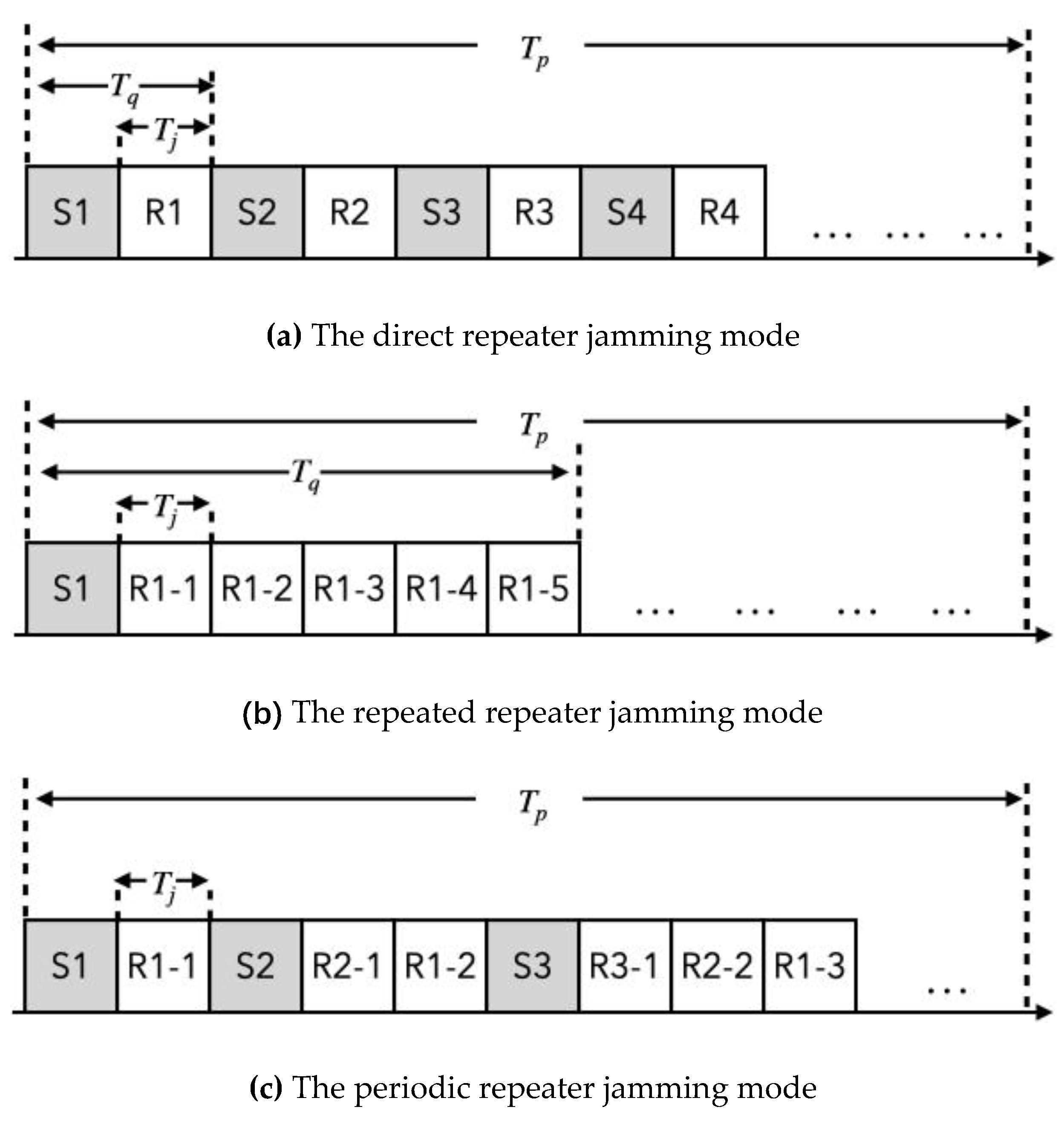
2. Mechanism of Different Interrupted-Sampling Repeater Jamming Modes
3. Intra-Pulse Orthogonal Waveform
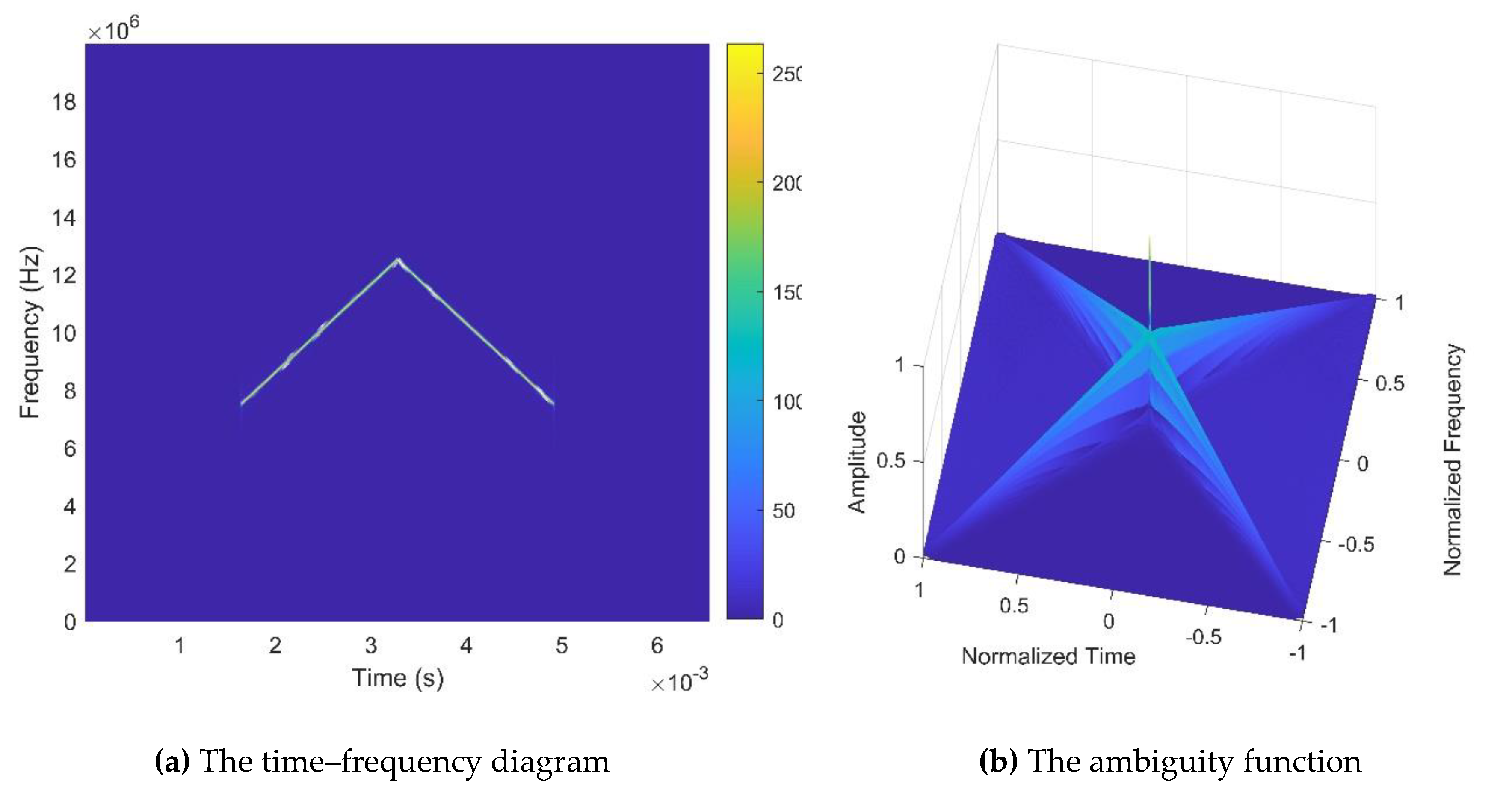
3.1 Waveform Design
3.2. Anti-interference Principle of the Intra-Pulse Orthogonal Waveform
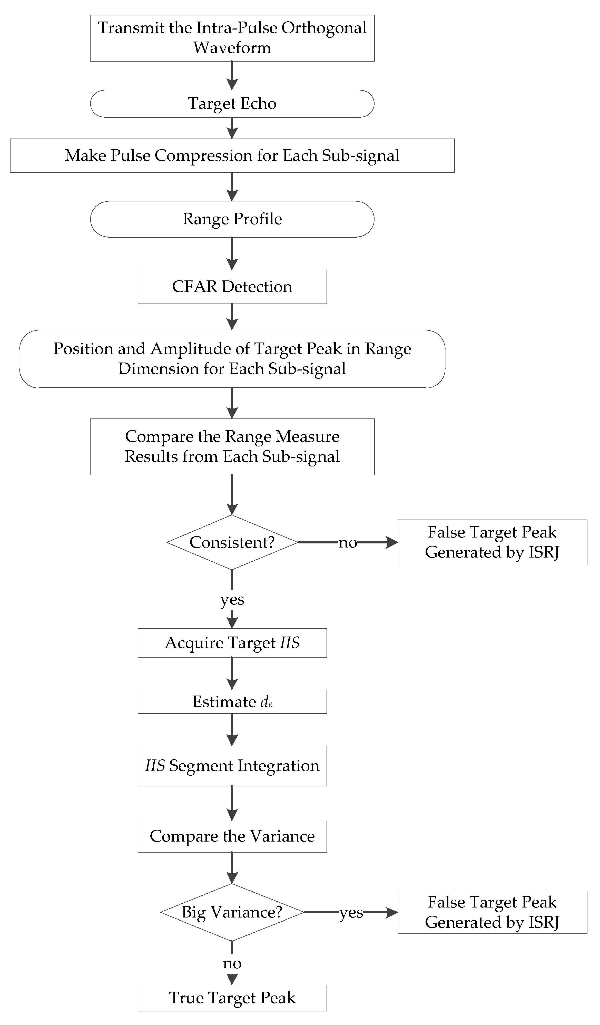
4. Interference Identification Algorithm based on Instantaneous Energy Integral
4.1. Interference Feature Extraction
4.2. Interference Feature Identification
5. Experiments
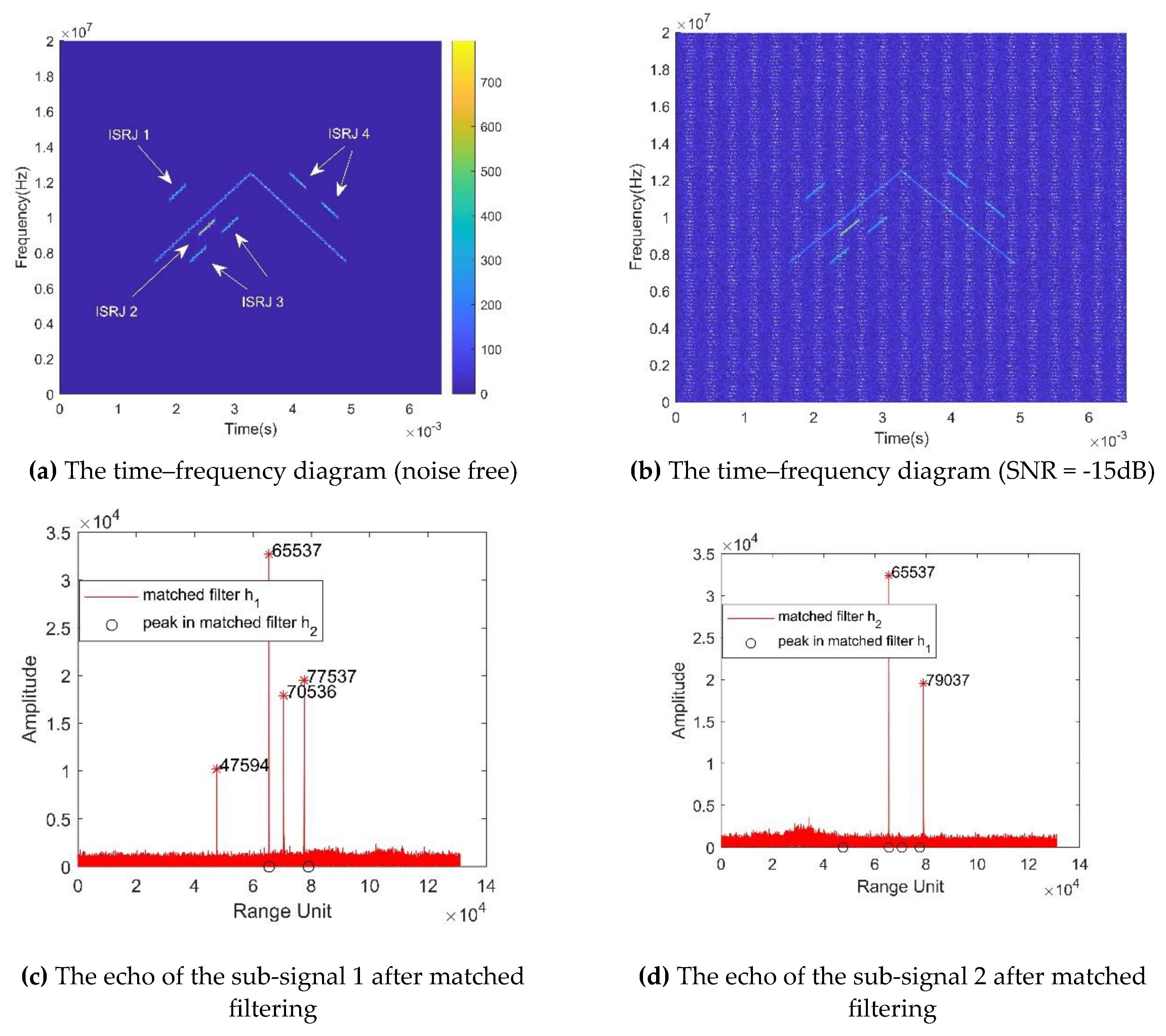
5.1. Anti-interference Experiments of the Proposed Waveforms
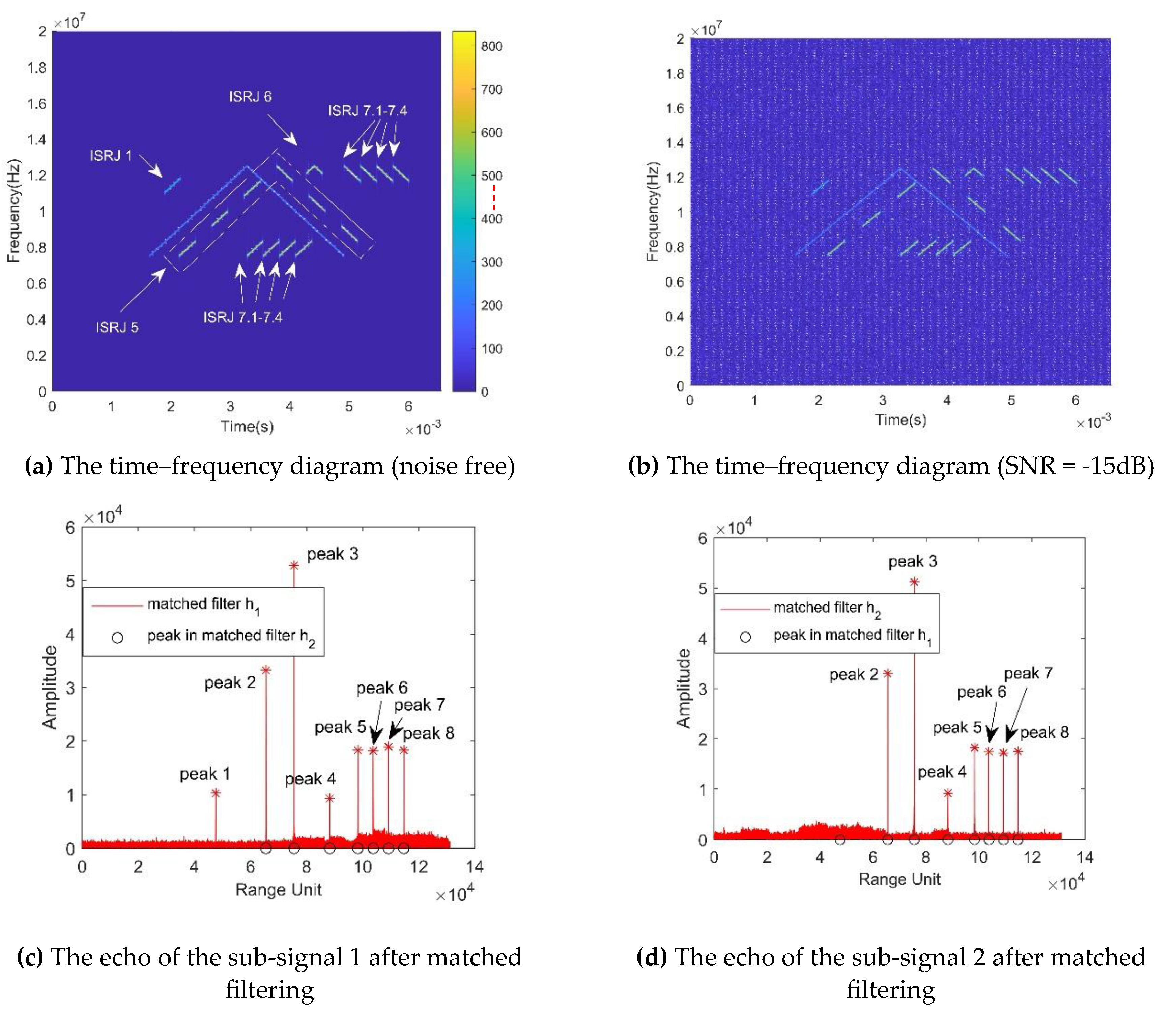
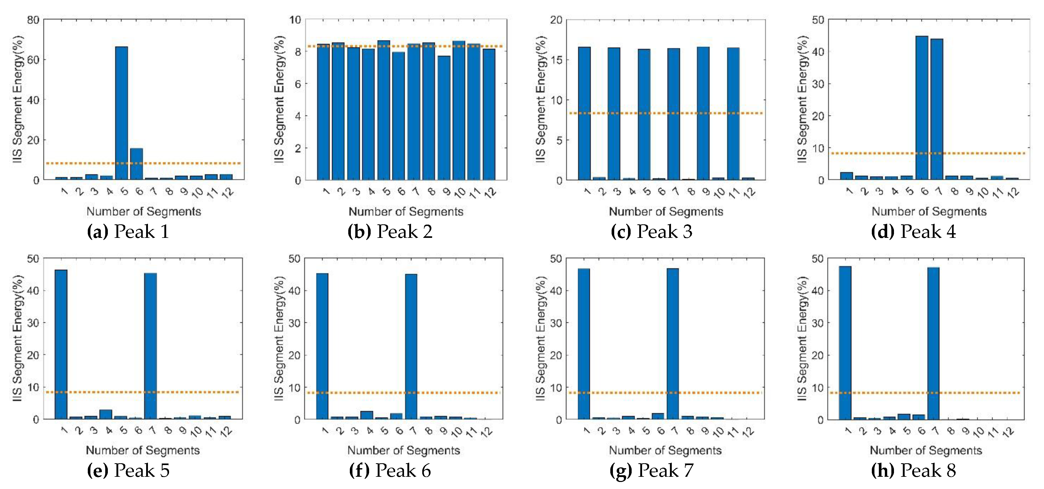
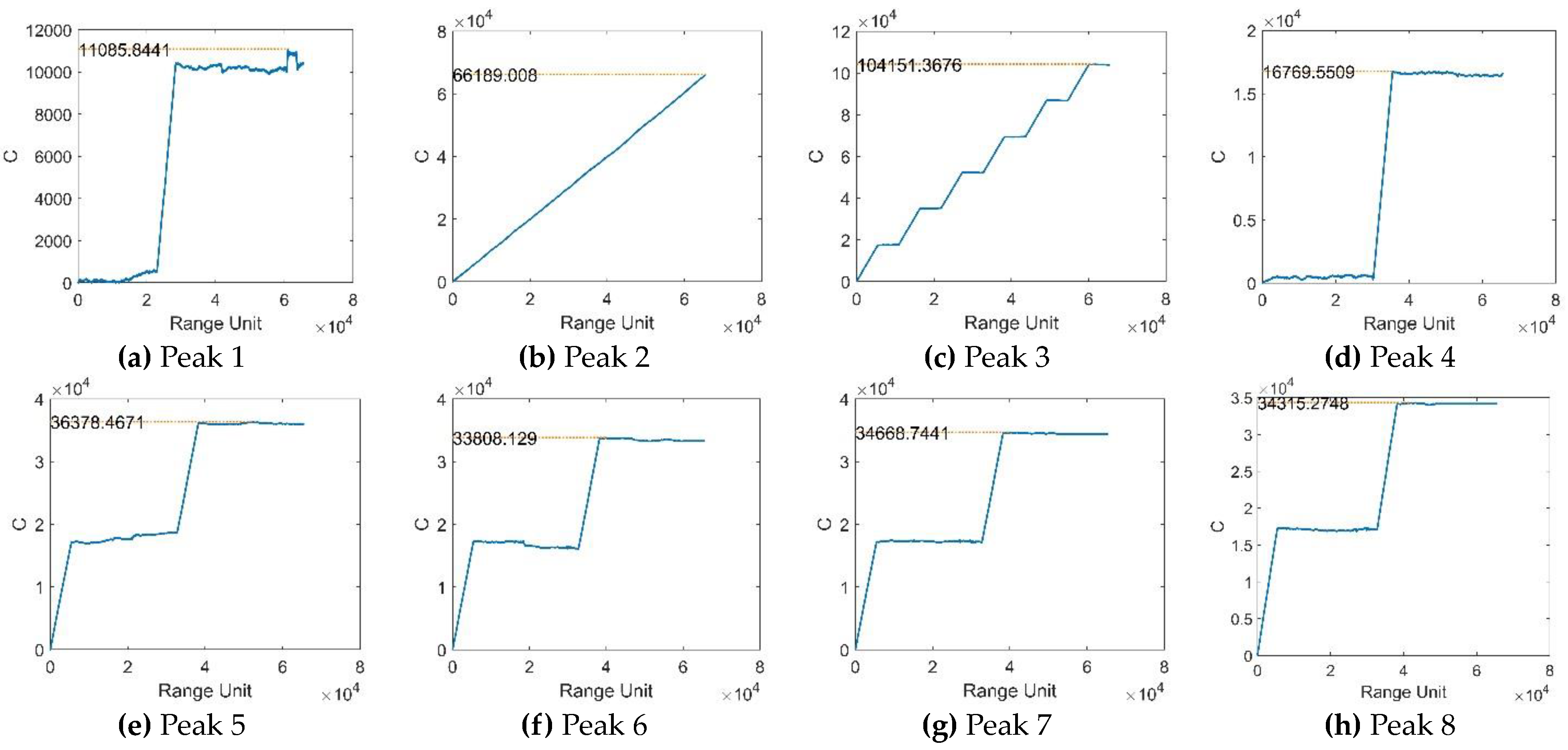
5.2. Anti-interference Experiments of the interference-identification algorithm
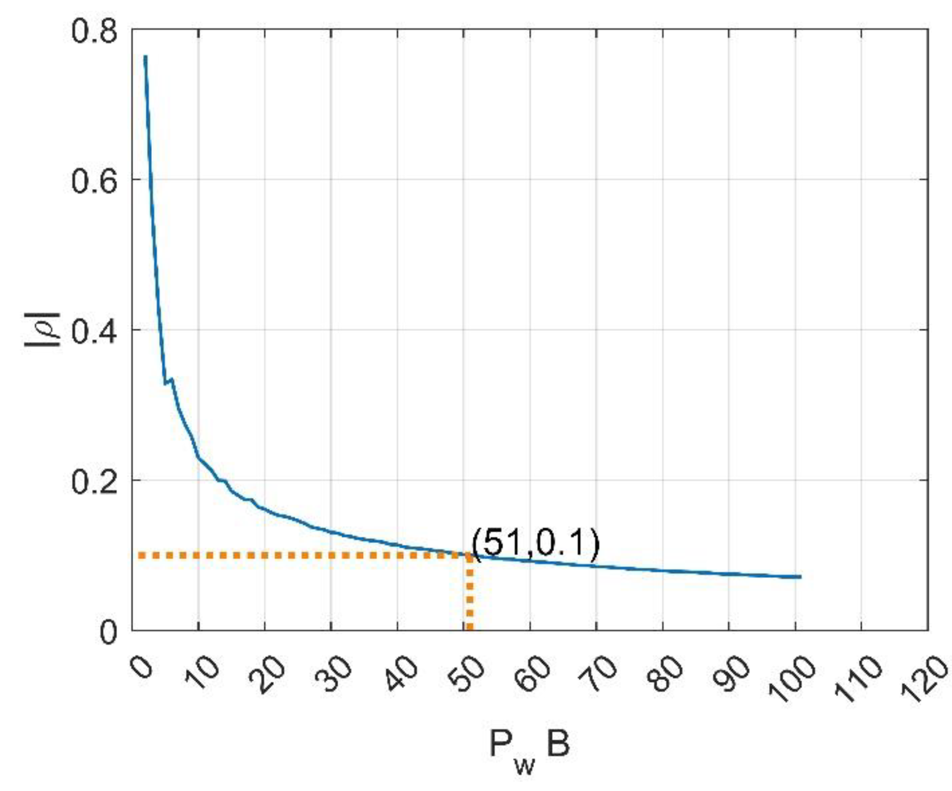
5.3. Robustness Analysis of the Proposed Orthogonal Waveform to Noise Interference
6. Conclusions
Author Contributions
Funding
Data Availability Statement
Acknowledgments
Conflicts of Interest
References
- Wang Xuesong, Liu Jiancheng, Zhang Wenming, et al. Mathematical principles of interrupted-sampling repeater jamming (ISRJ). Science in China(Series F) 2007, 50, 113–123. [Google Scholar]
- Jie Xiao, Xizhang Wei, Jia Sun. Research on Interrupted Sampling Repeater Jamming Performance Based on Joint Frequency Shift/Phase Modulation. Sensors (Basel, Switzerland) 2023, 23, 1424–8220. [Google Scholar]
- Jiyang Li, Xiaohu Duan, Jia Li, Peng Bai. Interrupted-Sampling and Non-Uniform Periodic Repeater Jamming against mDT-STAP System. Electronics 2022, 12, 152. [Google Scholar] [CrossRef]
- Gong SX, Wei XZ, Li X, Ling YS. Mathematic principle of active jamming against wideband LFM radar. Journal of Systems Engineering and Electronics 2015, 26, 50–60. [Google Scholar] [CrossRef]
- Yang Yi-qian, Wang Bo, Zou Pen. Jamming Performance Analysis of Interrupted Sampling Repeater Jamming to Phase Coded Radar. Shipboard Electronic Countermeasure 2021, 44, 45–49. [Google Scholar]
- Zhang Jing-ke,Dai Da-hai,Xing Shi-qi, et al. Analysis of jamming effect on intermittent sampling repeater jamming to CRPJ—SAR. Systems Engineering and Electronics 2015, 37, 1029–1034.
- Yang Yi-qian, Wang Bo, Zeng Ruiqi. Analysis of the Performance of Intermittent Sampling Repeater Jamming to LFM Radar. Shipboard Electronic Countermeasure 2021, 44, 28–34. [Google Scholar]
- X. , H., et al., LDA-MIG Detectors for Maritime Targets in Nonhomogeneous Sea Clutter. IEEE Transactions on Geoscience and Remote Sensing 2023, 61, 1–15. [Google Scholar]
- Y. Jiang, M. He, C. Yu, et al. Method of interrupted-sampling repeater jamming recognition based on box dimension. Mod. Def. Technol 2016, 44, 157–164. [Google Scholar]
- Y. Jiang, M.He, H.Liu, et al. Recognition of interrupted-sampling repeater jamming based on resemblance coefficient. Modern Radar 2016, 38, 72–76. [Google Scholar]
- J. Ying, W. B.-q., He Ming-hao, et al. A novel method of interrupted-sampling repeater jamming recognition based on correlation dimension. Fire Control & Command Control 2016, 41, 152–156. [Google Scholar]
- S. Gong, X. Wei, X. Li. ECCM scheme against interrupted sampling repeater jammer based on time-frequency analysis. Journal of Systems Engineering and Electronics 2014, 25, 996–1003. [Google Scholar] [CrossRef]
- Xiong, W. , Zhang G., Liu W. Efficient filter design against interrupted sampling repeater jamming for wideband radar. EURASIP Journal on Advances in Siganl Processing 2017, vol.2017, 1–12. [Google Scholar]
- Yuan H, Wang C Y, Li X, et al. A method against interrupted-sampling repeater jamming based on energy function detection and band-pass filtering. International Journal of Antennas and Propagation 2017, 2017, 1–9. [Google Scholar]
- Chen Jian, Wu Wenzhen, Xu Shiyou, et al. Band pass filter design against interrupted-sampling repeater jamming based on time-frequency analysis. IET radar, sonar & navigation 2019, 13, 1646–1654. [Google Scholar]
- Chen J, Xu S, Zou J, et al. Interrupted-sampling repeater jamming suppression based on stacked bidirectional gated recurrent unit network and infinite training. IEEE Access 2019, 7, 107428–107437. [Google Scholar] [CrossRef]
- Li Fei, Li Guolin, Nian Penglei. Radar signal deception jamming suppressing based on blind source separation. Journal of Naval Aeronautical and Astronautical University. Journal of Naval Aeronautical and Astronautical University 2015, 30, 424–428. [Google Scholar]
- C. Zhou, Q. Liu, T. Zeng. Research on DRFM repeater jamming recognition. Journal of Signal Processing. 2017, 33, 911–917.
- Zhou Chang, Tang Ziyue, Zhu Zhenbo, et al. Anti-interrupted sampling repeater jamming waveform design method. Journal of Electronics & Information Technology 2018, 40, 8. [Google Scholar]
- Xi, R.; Ma, D.; Liu, X.; Wang, L.; Liu, Y. Intra-Pulse Frequency Coding Design for a High-Resolution Radar against Smart Noise Jamming. Remote Sens. 2022, 14, 5149. [Google Scholar] [CrossRef]
- Xu, Z.; Xue, S.; Wang, Y. Incoherent Interference Detection and Mitigation for Millimeter-Wave FMCW Radars. Remote Sens. 2022, 14, 4817. [Google Scholar] [CrossRef]
- Zhou Chang, Tang Ziyue, Yu Fangli, et al. Anti-intermittent sampling repeater jamming method based on intrapulse orthogonality. Systems Engineering and Electronics 2017, 39, 8. [Google Scholar]
- Wang Fulai, Pang Chen, Yin Jiapeng, et al. Joint design of doppler-tolerant complementary sequences and receiving filters against interrupted sampling repeater jamming. Journal of Radars 2022, 11, 11.
- Zhou Kai, Li Dexin, Su Yi, He Feng, Liu Tao. Joint transmitted waveform and mismatched filter design against interrupted-sampling repeater jamming. Journal of Electronics & Information Technology 2021, 43, 8. [Google Scholar]
- Zhou Chao, Liu Quanhua, Hu Cheng. Time-frequency analysis techniques for recognition and suppression of interrupted sampling repeater jamming. Journal of Radars 2019, 8, 100–106. [Google Scholar]
- Liu Jiancheng, Liu Zhong, Wang Xuesong, et al. Research on forward interference based on group delay. Progress in Natural Science 2007, 17, 7. [Google Scholar]
- Jiang Yisong. Study of orthogonal wave form based on phase-coding method. Master degree, University of Electronics Science and Technology of China, Chengdu China, 2015.
- Gabor, D. Theory of communications. J. Inst. Elec. Eng, 1946, 93. [Google Scholar] [CrossRef]
- Huang Shipan, Zheng Lin, Yang Chao, et al. A binary orthogonal chirp signal modulation method with delay offset. Computer Engineering 2017, 34, 6. [Google Scholar]
- Yingxiao ZHAO, Zengping CHEN, Yue ZHANG et al. Hybrid integration method for highly maneuvering radar target detection based on a Markov motion model. Chinese Journal of Aeronautics 2020, 33, 1717. [Google Scholar] [CrossRef]
- D. Luong, A. Young, B. Balaji et al. Classifying Linear Frequency Modulated Radar Signals Using Matched Filters. 2022 IEEE Canadian Conference on Electrical and Computer Engineering (CCECE) 2022, Canada, 11. [Google Scholar]
- Jin, Yan; Duan, Pengting; Ji, Hongbing. Parameter Estimation of LFM Signals Based on Scaled Ambiguity Function. Circuits Systems and Signal Processing 2016, 35, 4445. [Google Scholar] [CrossRef]


| Parameter | Value |
|---|---|
| Pulse width of the transmitted waveform (twice the sub-signal pulse width) |
3.28 ms |
| Bandwidth of the transmitted waveform | 5 MHz |
| Center frequency of the transmitted waveform | 10 MHz |
| SNR | -15 dB |
| Time duration of signal receiving | 6.56 ms |
| Complex sampling rate | 20 MHz |
| Pulse width of the interference signal | 273 μs |
| JSR | 5 dB, 10 dB |
| Frequency shift of the interference slices (partial interference signal) |
3.5 MHz |
Disclaimer/Publisher’s Note: The statements, opinions and data contained in all publications are solely those of the individual author(s) and contributor(s) and not of MDPI and/or the editor(s). MDPI and/or the editor(s) disclaim responsibility for any injury to people or property resulting from any ideas, methods, instructions or products referred to in the content. |
© 2023 by the authors. Licensee MDPI, Basel, Switzerland. This article is an open access article distributed under the terms and conditions of the Creative Commons Attribution (CC BY) license (http://creativecommons.org/licenses/by/4.0/).


