Preprint
Review

Optimization of Thermal Energy Harvesting Road Pavement using Sustainable Conductive Material in Malaysia by Numerical Simulation

Altmetrics

Downloads

146

Views

63

Comments

0

Submitted:

03 July 2023

Posted:

04 July 2023

You are already at the latest version

Alerts
Abstract
Solar pavement technology has numerous benefits for advanced life and environmental protection, including reduced fossil fuel usage, reduction harmful emissions from conventional electricity generation and handy reliable electricity via solar energy. This paper aims to find an alternative for cost effective renewable energy sources is in conjunction with the principles of sustainability. This research studies whether the application of thermal energy harvesting road pavement using sustainable conductive piping such as stainless steel, copper, and aluminium are feasible in Malaysia. The scope of the paper is to optimize the suitable parameters for different materials of thermal energy harvester such as pipe material, pipe depth inserted into pavement, types of pipe arrangement, pipe spacing, and flow rate for maximum thermal energy extraction using numerical simulation. The simulation is testing under engineering software ANSYS Workbench 19.2 (Fluent) and Solidworks 2020 to develop project prototype from optimize thermal energy harvester. Thus, serpentine copper pipe shows the highest heat efficiency which is 32.22% with the temperature outlet of 327.35K (54.21°C) at the pipe located at 50 mm from the surface pavement with the pipe spacing of 80 mm centre-to-centre.
Keywords: 
Subject: Engineering  -   Civil Engineering

1. Introduction

The global resource crisis is intensifying and irreplaceable resources are being depleted. Solar energy is becoming increasingly popular as a renewable resource. Since roads cover a significant part of the earth's surface, they are an ideal place to collect and use solar energy. Solar pavements and asphalt pavements are two of the most common uses of solar energy. Solar conversion is one of the most adaptive strategies to meet future energy needs. Phase change materials (PCMs) use their latent heat to allow the bitumen to absorb or release large amounts of heat even when the surrounding conditions remain constant. The development of solar pavements and asphalt pavements illustrates the fundamentals of solar energy production and heat utilization. History of materials used in asphalt pavements and future predictions for solar pavements.
The advantages of solar energy, such as cleanliness, environmental protection, and high energy density, have won the favour of most experts with the continuous development of technology. As a renewable energy source, solar energy is a key link in solving problems such as pollution caused by traditional fossil fuels and the depletion of natural resources. On the one hand, solar energy collected the temperature from asphalt roads with generate outlet electricity can be used to power buildings or other uses. It reduces the use of traditional energy sources and contributes greatly to solving the energy crisis. Therefore, the use of renewable green energy can help reduce the urban heat island effect by reducing carbon dioxide emissions and other forms of pollution. Change can happen in public institutions simply by considering the close connection between the 17 Sustainable Development Goals (SDGs).

1.1. Transformations to Achieve the Sustainable Development Goals (SDG)

Both the Sustainable Development Goals (SDGs) and the Paris Agreement on climate change require major changes in all countries. To achieve this change, governments, civil society, academia and business need to work together and act in concert. Based on previous work by The World in 2050 initiative, six (6) SDG transitions were introduced as modular elements to achieve the SDGs: (1) education, gender and inequality; (2) health, welfare and demographics; (3) Energy decarbonization and sustainable industries; (4) sustainable food, land, water and oceans; (5) sustainable cities and communities; (6) Digital revolution for sustainable development [1]. Each transformation identifies priority investments and regulatory problems, which necessitates action on the part of well-defined government agencies working in conjunction with business and civil society [1].
The development of Artificial Intelligence (AI) is having an impact on an increasing number of business sectors. It is projected that AI will have both short-term and long-term implications on a variety of sectors, including global productivity, equality and inclusion, environmental outcomes, and others [2]. There have been reports of both good and negative possible repercussions that artificial intelligence may have on sustainable development. Presentation and discussion of the potential consequences of how artificial intelligence can either help or harmed attempts to meet the 17 goals and 169 targets defined in the 2030 Agenda for Sustainable Development. The aforementioned approaches were used to define the relationships, and these methodologies can be summed up as a consensus-based expert elicitation procedure that was meant to map the interlinkages between the Sustainable Development Goals [3].
In order to achieve SDGs 7 (Affordable and Clean Energy) and 11 (Quality Education), Artificial Intelligence (AI) can enable smart and low-carbon cities with a wide range of interconnected technology, including electrical autonomous vehicles and smart appliances (Sustainable Cities and Communities). By allowing smart grids to partially match energy usage to periods when the sun and wind are shining, AI can also aid in the integration of variable renewables [4].
The last group of SDGs, i.e., the one related to Environment, is analyzed three goals to do with climate change, underwater life, and life on land (SDGs 13, 14, and 15). One benefit of artificial intelligence could be the ability to look at large, connected databases to find ways to work together to protect the environment [5]. Taking SDG 13 on climate action into account, there is evidence that progress in AI will make it easier to understand climate change and model its possible effects. Furthermore, AI will make it possible for low-carbon energy systems with a lot of renewable energy and energy efficiency, all of which are needed to fight climate change.

1.2. Solar Paver Technologies for the Advancement of Environmental Sustainability in Malaysia

The previous researcher’s study was conducted in Malaysia to investigate the challenges and potentials of implementing solar farm technology. The report is based on the opinions of those with an interest in the Malaysian construction industry. Broadly speaking, solar installation technology is a solar panel that can be placed on existing roads like concrete pavers, generating clean energy from the sun's exposed surface. If solar cell technology works, it could power road systems such as streetlights and traffic lights without relying on a centralized national power system. In addition, solar pavers can be used on roads where both cars and people travel. This technique is still very new in the construction industry.
Pavements are essential to the supply of roads and walking paths. There are different kinds of pavements based on the materials they are made of and how they are put together. As an example, there are three types of asphalt pavements: hot-mix, stone-mastic, and cold-mix. Other common types of pavements are made of concrete or a mixture of materials (with or without steel reinforcement). It is thought that building and maintaining pavements are responsible for 10% of the carbon emissions made by the transportation sector [6]. This shows how important pavements are for developing in a way that is good for the environment and making transportation better. There are environmental effects and emissions that come from getting resources, processing them, building pavements, keeping them in good shape, and getting rid of them when they are done.
Solar Paver technology is a panel of photovoltaic cells that can be used as concrete pavers on existing road networks to make renewable energy by taking advantage of sunny, open surfaces. Solar pavers can be used on roads for both cars and people. Even though this technology is new, some of the first research has been done on how it can be used and adapted. The study came to the conclusion that solar pavers could be used as an alternative way to use land by generating off-grid power for road infrastructure like streetlights and reducing carbon emissions from generators that use fossil fuels [7]. Solar pavers, on the other hand, were not as useful as rooftop solar panels because they did not produce as much power and did not work as well in bad weather. Even though this preliminary research gives us important information, the potential of the technology makes it necessary to learn more about how it will be made and how people will react to it. To analyses and use solar paver technology correctly, it is necessary to know more about the structure, business models, road design elements, and stakeholder operational strategies of the construction industry.

1.3. Pavement Energy Harvesting Technologies

With rising global energy demand, scientists are constantly looking for novel ways to gather power. Pavement engineers can make use of energy from the sun and car weight. Semi-transparent solar cells (photovoltaic highways) enable these systems to convert sunlight into electricity, while solar thermal systems can convert solar energy into heat. Heat pipes, thermoelectric generators, and heat-transfer fluids (like water) pushed through a medium can all take advantage of the temperature gradient of the pavement (asphalt solar collectors, porous layer, or air conduits). Use of piezoelectric materials allows the vehicle's weight to be transformed into an electric charge.

1.3.1. Asphalt Solar Collector

The asphalt's surface temperature can rise to around 70°C when exposed to sunlight, speeding up the rutting (permanent deformation of pavements) and oxidation of asphalt (causing changes in viscosity, component separation, embrittlement, and loss of cohesion) [8]. Solar collectors made from asphalt are a practical means of lowering pavement temperatures and making the most of available solar energy. They are made up of pipes that are surgically implanted in asphalt and can extract heat energy via a fluid (i.e., water). To compensate for the fluid's lower temperature, heat is transmitted from the asphalt. Therefore, a cool fluid is introduced while a hot fluid is removed from the system.
The energy balance of an asphalt solar collector includes the following materials and environments: i) asphalt pavement, ii) pipes, iii) atmosphere, and iv) fluids flowing through the pipe network [9]. In terms of heat exchange mechanisms, the energy is initially balanced across the entire pavement-atmosphere contact in terms of heat exchange mechanisms. The asphalt absorbs heat from the sun, transfers some of that heat to the surrounding air by convection and emits some of its own heat into space. Because of the change in temperature brought on by the heat flow, the road's surface heats up before its interior, a process known as conduction. First, conduction occurs at the asphalt-pipe junction, and then convection takes place at the asphalt-fluid contact.

1.3.2. Air-Powered Energy Harvesting Pavement

Solar collectors need a thermal fluid to extract energy from the asphalt. Pipe leaks can cause road surface deterioration. However, the presence of cracks in the pipes can endanger the entire system, release fluids and risk damage to the coating to imbed into the pavement a series of conduits, using the air as heat fluid [10]. Reported by the other researchers, air conduits are connected to upward and downward chimneys, and due to the temperature difference between the environment and the asphalt, a pressure difference is created between the end of the chimney and the entrance to the pavement. This results in a steady breeze that can reduce the asphalt temperature by up to 10 percent in the summer and raise it by the same amount in the winter [11]. The system's viability was confirmed by early results from a laboratory prototype, which highlighted the following:
i.
When the pipes are laid out in a single row beneath the pavement wearing course, the air velocity is maximised and the surface temperature is reduced.
i.
ii. Concrete corrugations can be used instead of the pipes, but they reduce the amount of energy that can be collected.
According to the literature research, the available studies paid scant attention to the effectiveness of pipe arrangement in heat dynamics and PSC performance. As a result, the current work includes an experimental and numerical analysis to analyse this crucial technical specification on the thermal performance of the built PSC based on the temperature measured in Malaysia. An experimental test setup was conceived and built to achieve this purpose. In addition, a numerical model was created and verified using the experimental data to optimise the embedded pipe arrangement using different types of piping material, numerous configurations were constructed and analysed by the validated numerical model to discover the best pipe layout.
With a purpose to comprehend intention-behaviour gap about acceptance of solar energy road pavement, the research gap arises from the literature review based on previous researcher. The comparison of pipe material, pipe depth, pipe spacing, pipe arrangement, output temperature, and flow rate for maximum thermal energy extraction were not clearly stated. Thus, in this paper, the optimum thermal energy harvesting road pavement using sustainable conductive material either stainless steel, copper or aluminium in Malaysia will be present in the outcome with the supporting from piping inserted into asphalt pavement.

2. Preparation of Numerical Simulation Model

In this section provides the methodology on how the project is done and investigated. It includes the relevant scope of study in using Solidworks 2020 and Ansys Workbench 19.2 (Fluent) software to do the simulation of the project. There is boundary condition involved in the simulation. This project will cover an investigation and result comparison between simulation and experimental works. The obtain results will be compared and validate in the present of tabulated data and graphical distribution.
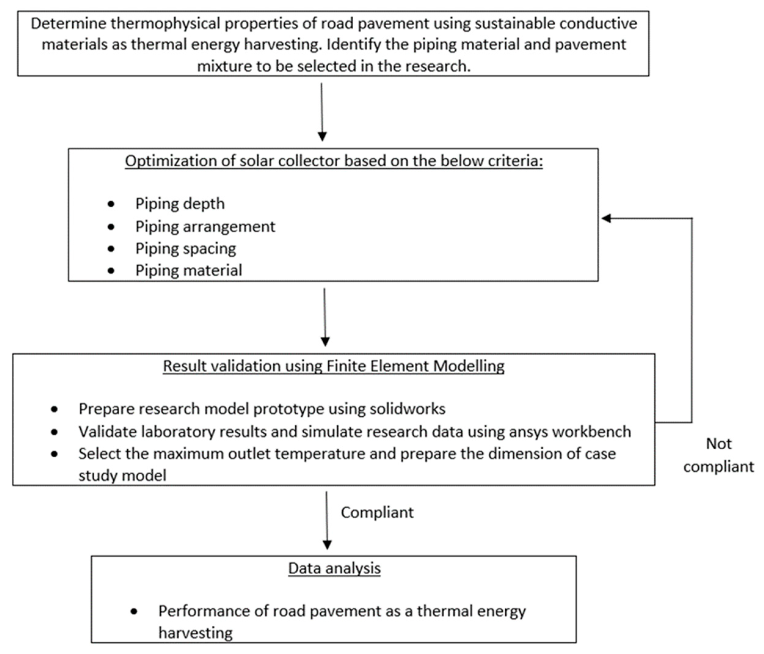
Figure 1 shows the process and strategies of performance of road pavement as a thermal energy harvester to get the maximum temperature extract. Selected piping material are sustainable conductive material of stainless steel, aluminium, and copper. Research model prepared using Solidworks 2020 and transfer to Ansys Workbench 19.2 (Fluent) for simulation purpose.

2.1. Research Model with Inserted Serpentine and Series Pipe

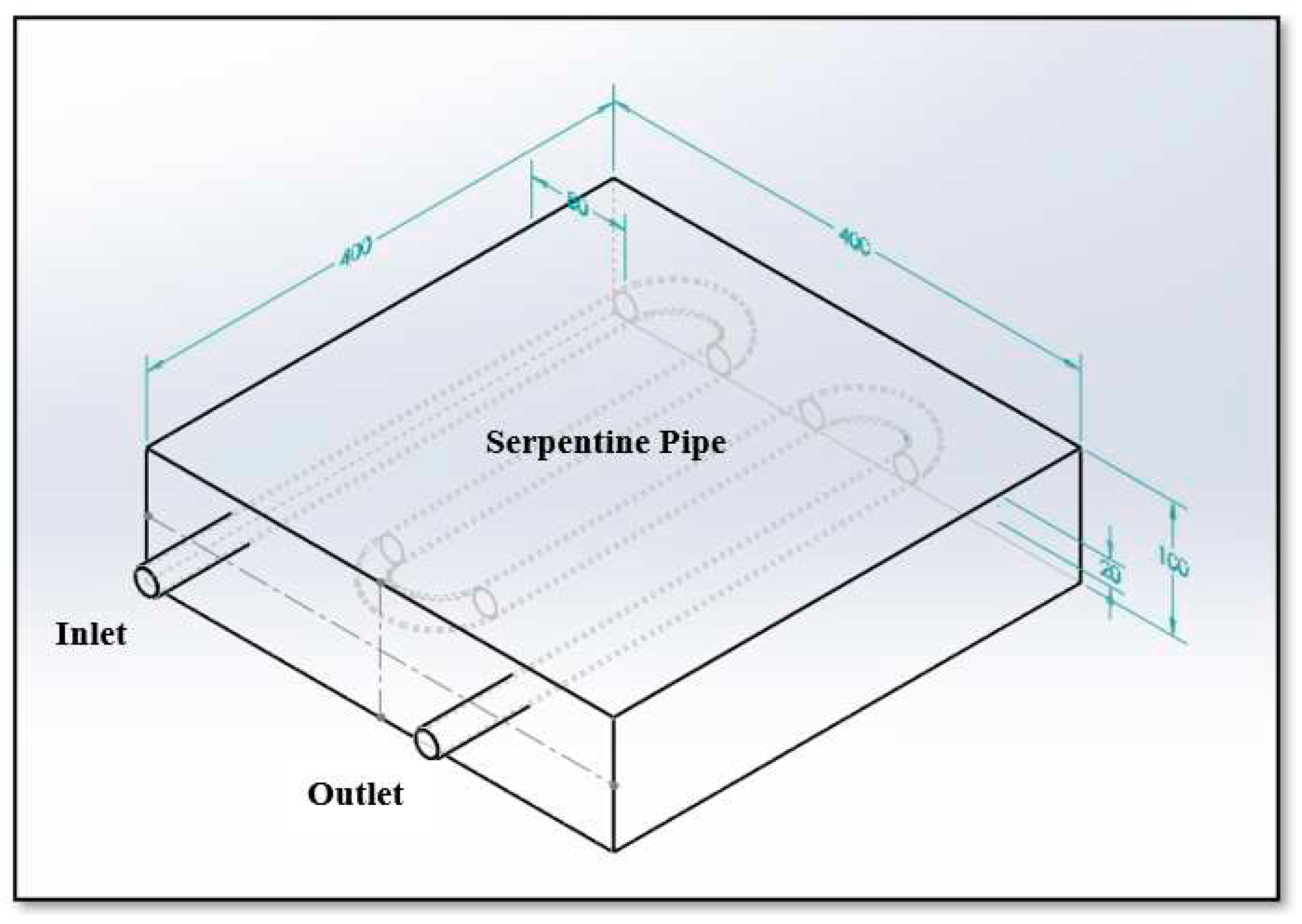
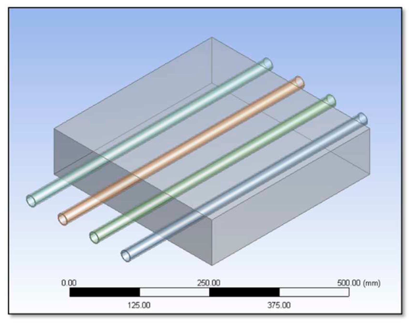
The asphalt pavement model is design using Solidworks 2020 software. The types of models is asphalt pavement with inserted serpentine and series piping with difference depth (30mm, 40mm, 50mm, 60mm, 70mm, and 80mm) from surface pavement. Three types of pipe material used which are stainless steel, copper and aluminium. The dimension for model is 400mm x 400mm x 100mm with the diameter of piping is 20mm. The fluid flow containing inside the piping is water and the velocity of the water is stagnant. Figure 2 and Figure 3 shows the configuration of the project model.

2.2. Prototype of Finite Element Simulation using Ansys Workbench 19.2 Fluent

The asphalt pavement layer designed an isotropic material as a 3-dimensional and investigated the effects of mechanical stress and temperature distribution with respect to different temperature faces according to the finite element method (FEM). In this study, the main purpose of using Ansys software with finite element method is to pre-check the simulation studies with the data properties to the application stage of mechanical improvements according to the parameters determined on asphalt pavement.
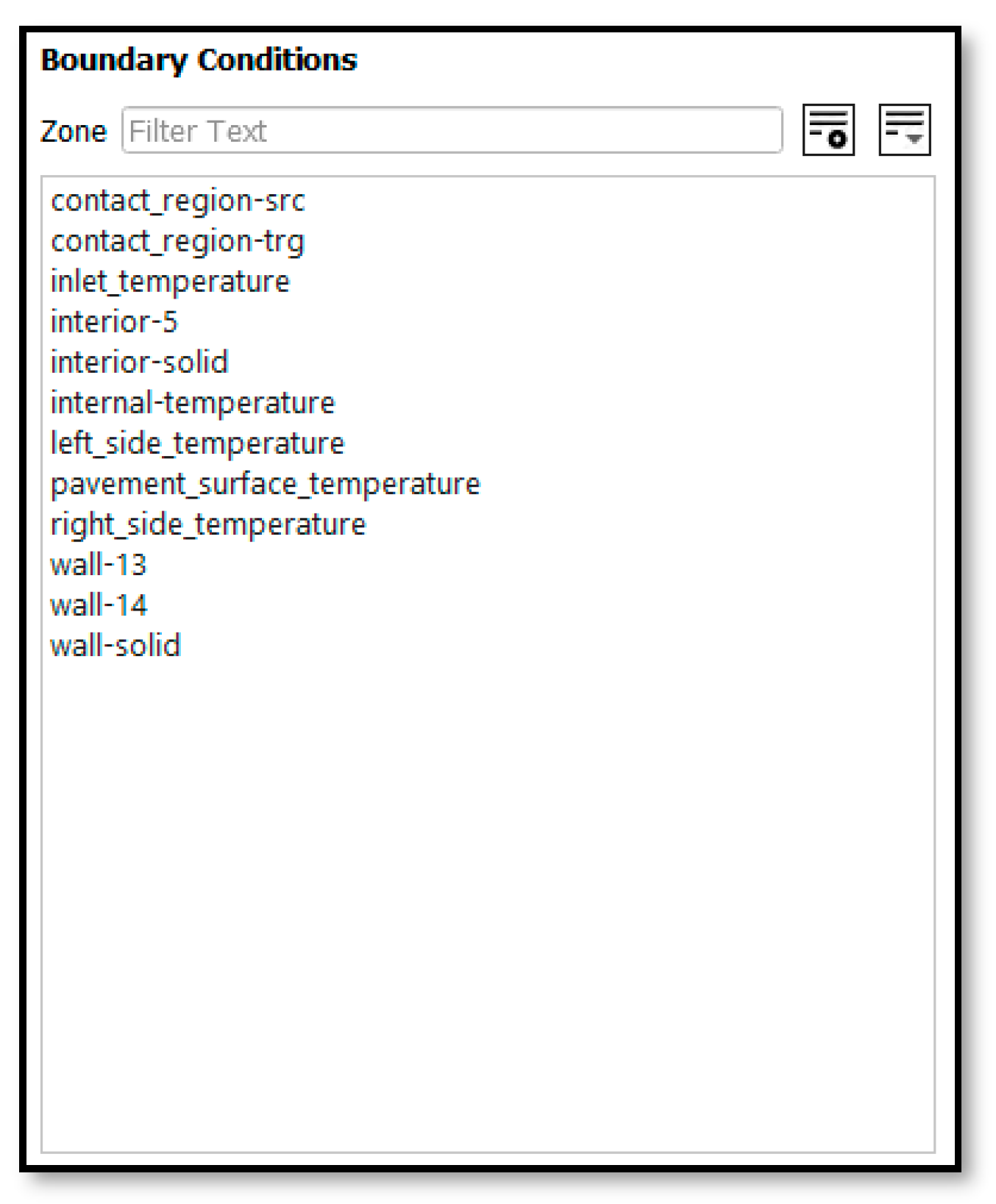
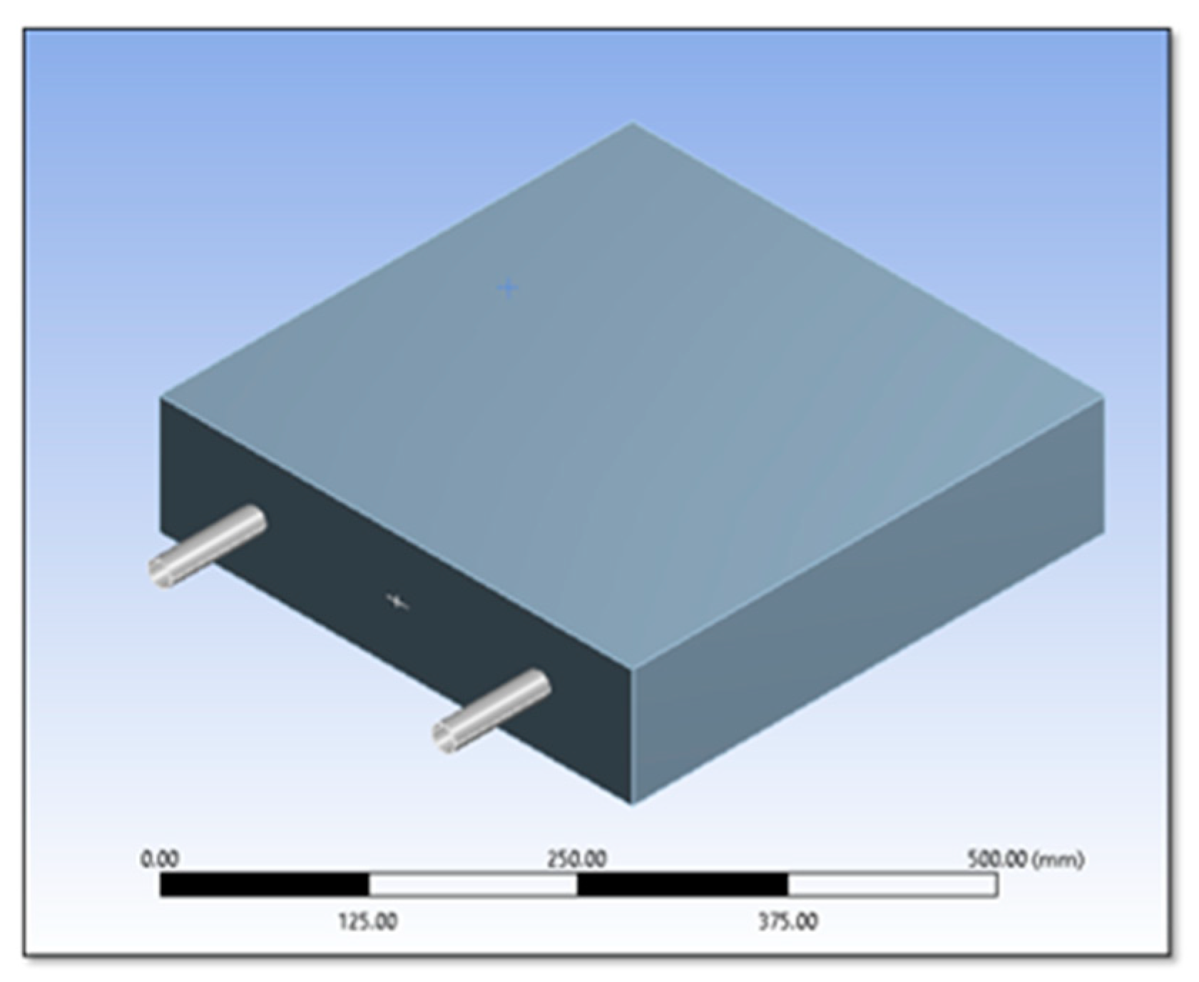
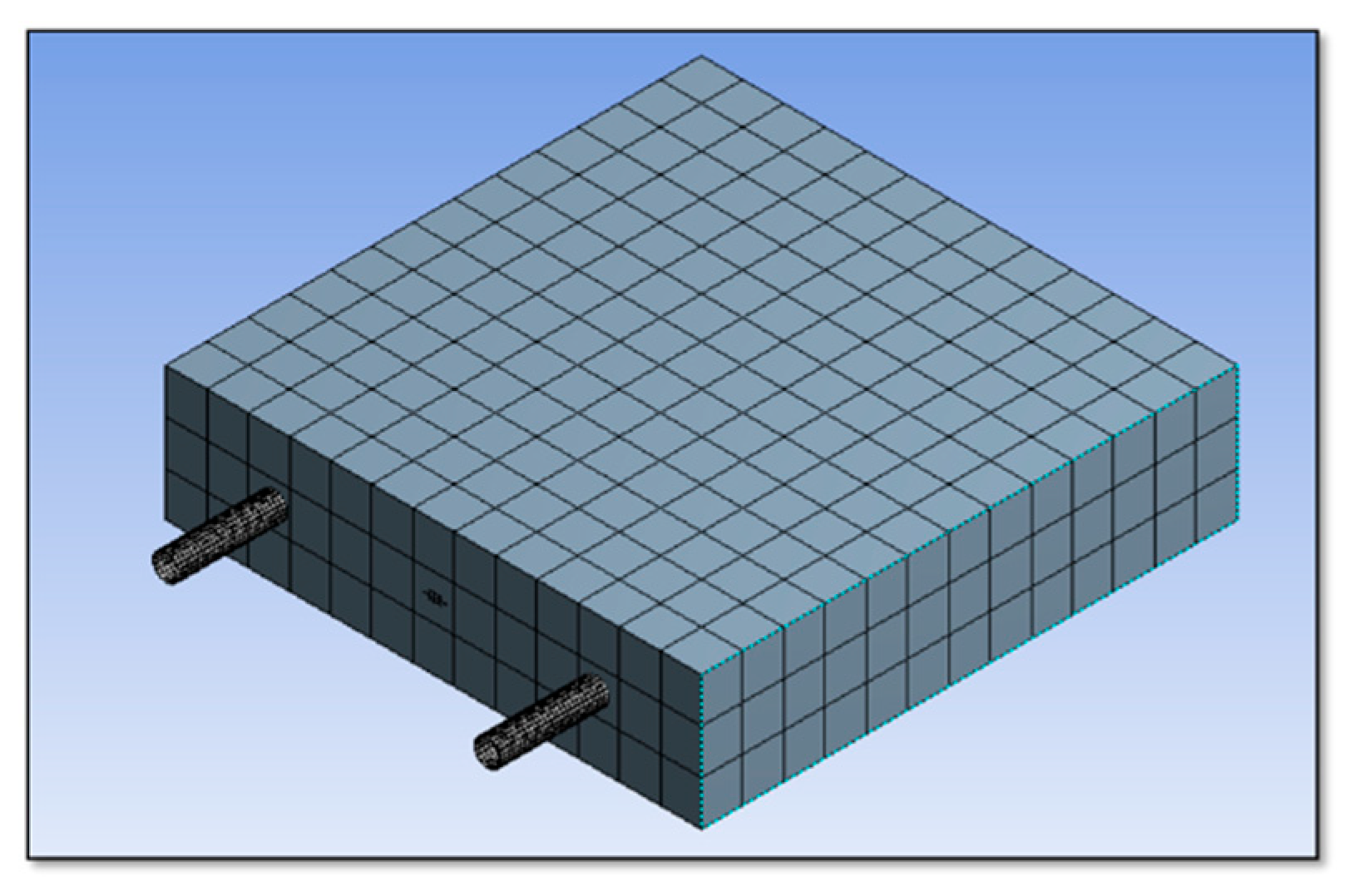
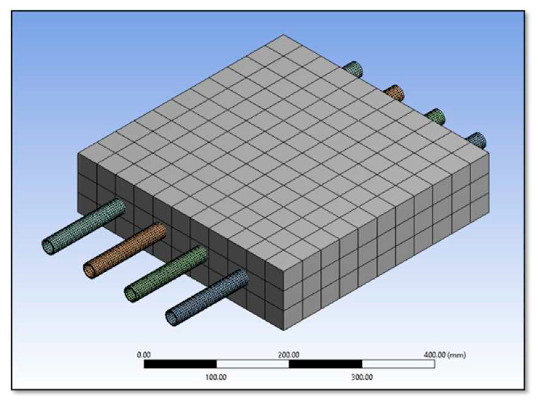
Model is set up from Ansys Workbench (Fluent) that import from Solidworks 2020 software. The pipe depth is simulated from 30mm, 40mm, 50mm, 60mm, 70mm and 80mm from surface of asphalt pavement. The pipe material changed to stainless steel, copper, and aluminium for each time during simulation works. Two contact regions are created whereby contact region 1 is between pavements and pipe where else contact region 2 is between pipe and fluid flow. Model named selection cover for pavement surface temperature, left and right side temperature, inlet temperature and internal temperature. Boundary conditions were set based on data properties. Figure 4 and Figure 5 shows the model with serpentine pipe while Figure 6 and Figure 7 shows the model with series pipe.

2.3. System Set Up into Ansys Workbench 19.2 (Fluent)

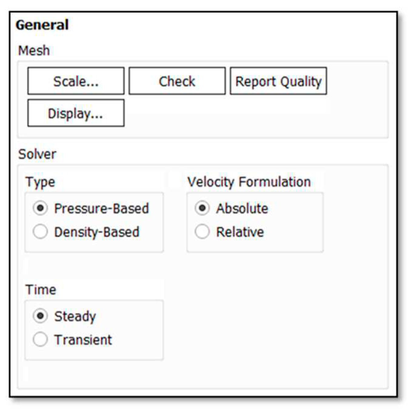
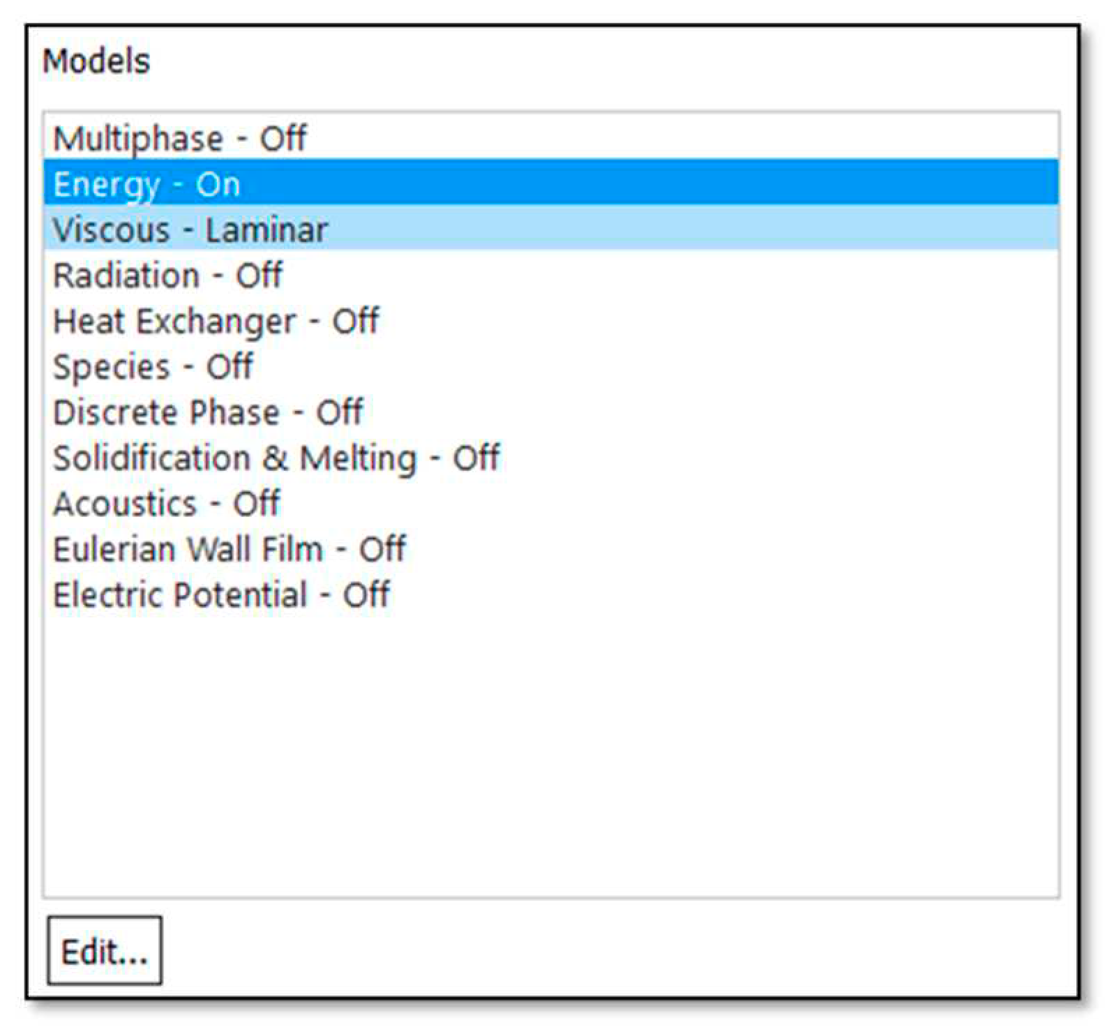
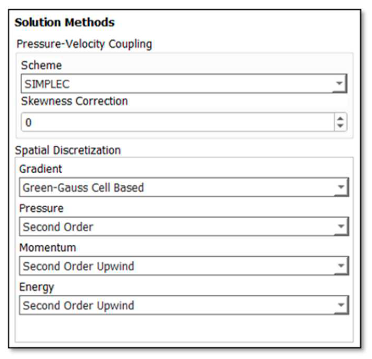
The model is set up for its energy, materials (fluid and solid), temperature, wall shear between asphalt pavement and velocity. Figure 8 until Figure 12 shows the related set-up into the software.
Figure 8. The solver is based on pressure and absolute velocity formulation.
Preprints 78353 g008
Figure 9. The model under energy and viscous laminar.
Preprints 78353 g009
Figure 10. Types of boundary conditions.
Preprints 78353 g010
Figure 11. Types of solution methods.
Preprints 78353 g011
Figure 12. Types of solution initialization.
Preprints 78353 g012

2.4. Input of Data Properties

Table 1 until Table 3 shows the parameter input into Ansys Workbench 19.2 (Fluent) to run the simulation.

3. Results and Discussion

3.1. Optimization of the Thermal Energy Harvesting Serpentine Piping System using Numerical Simulation

3.1.1. Piping Depth for Copper Pipes

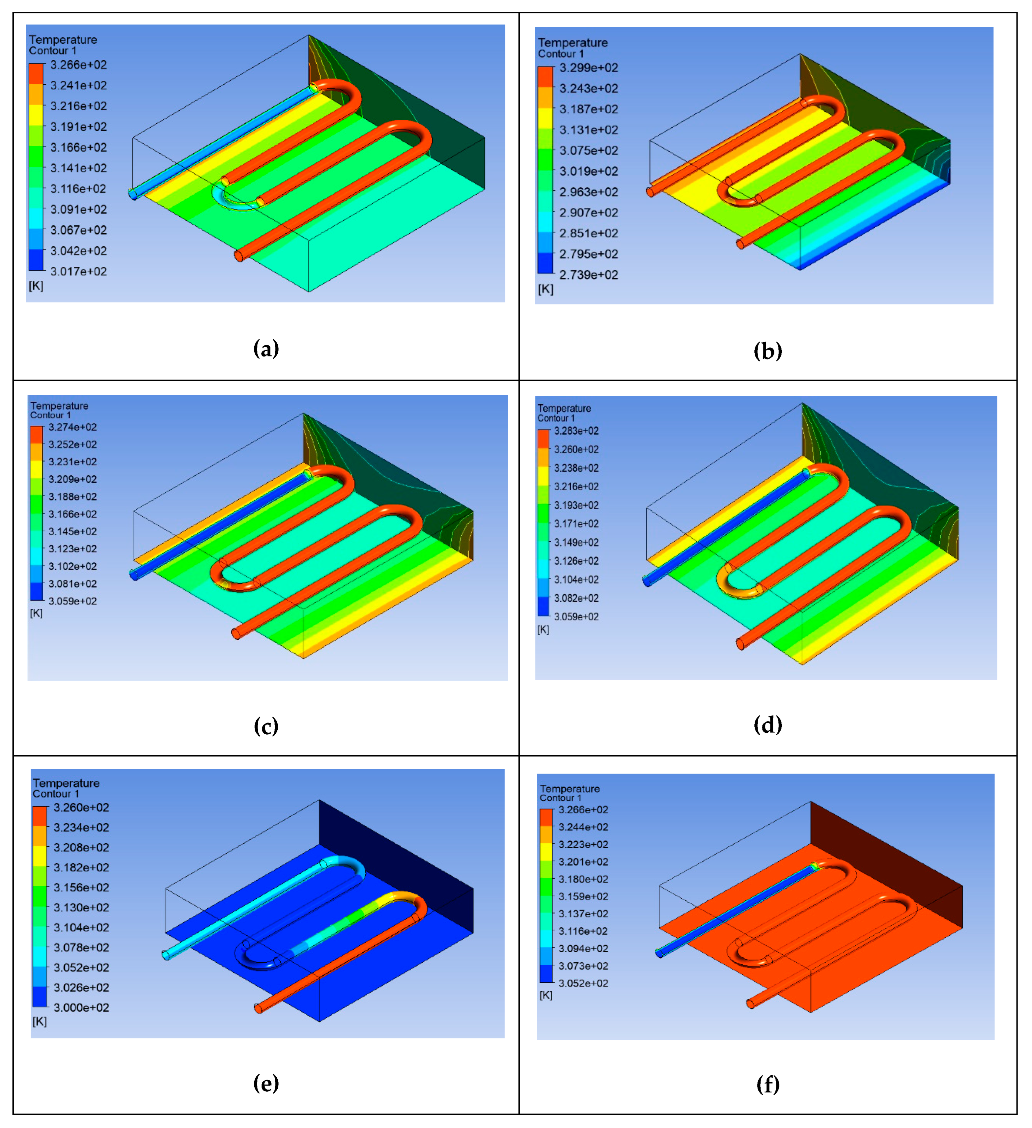
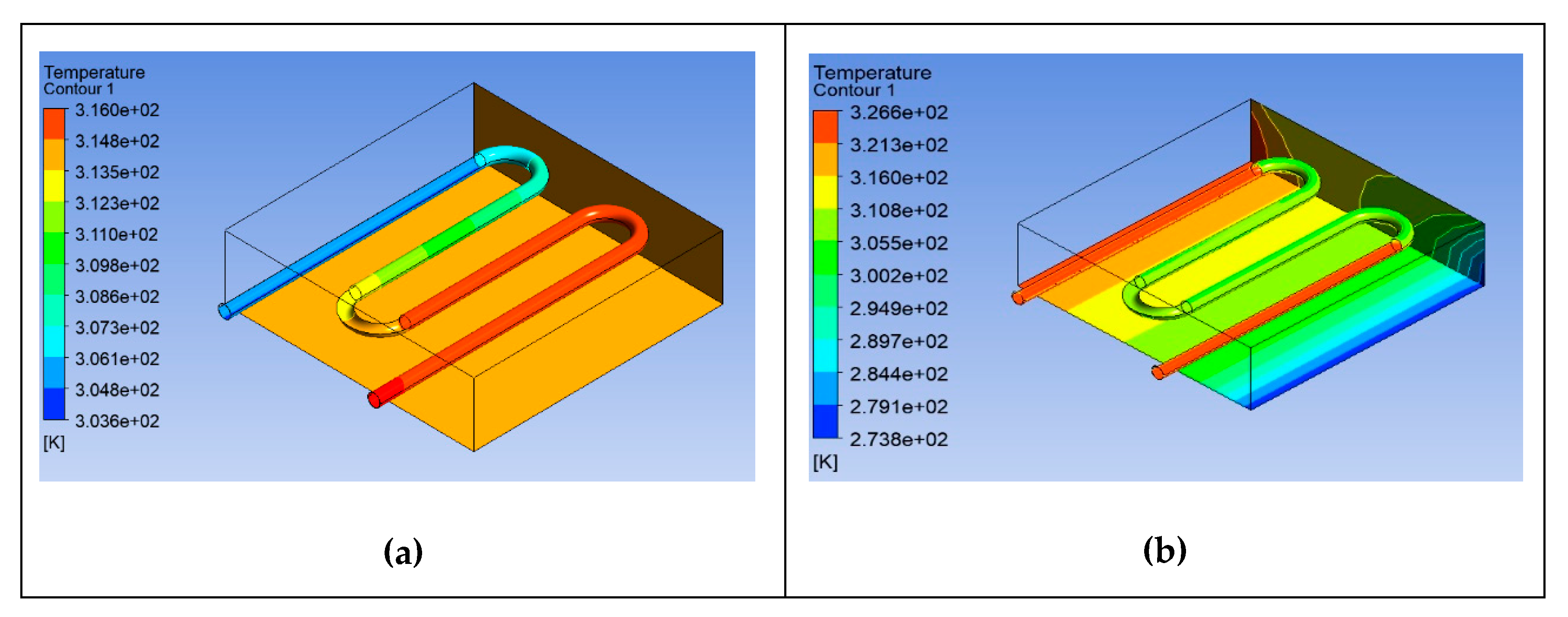
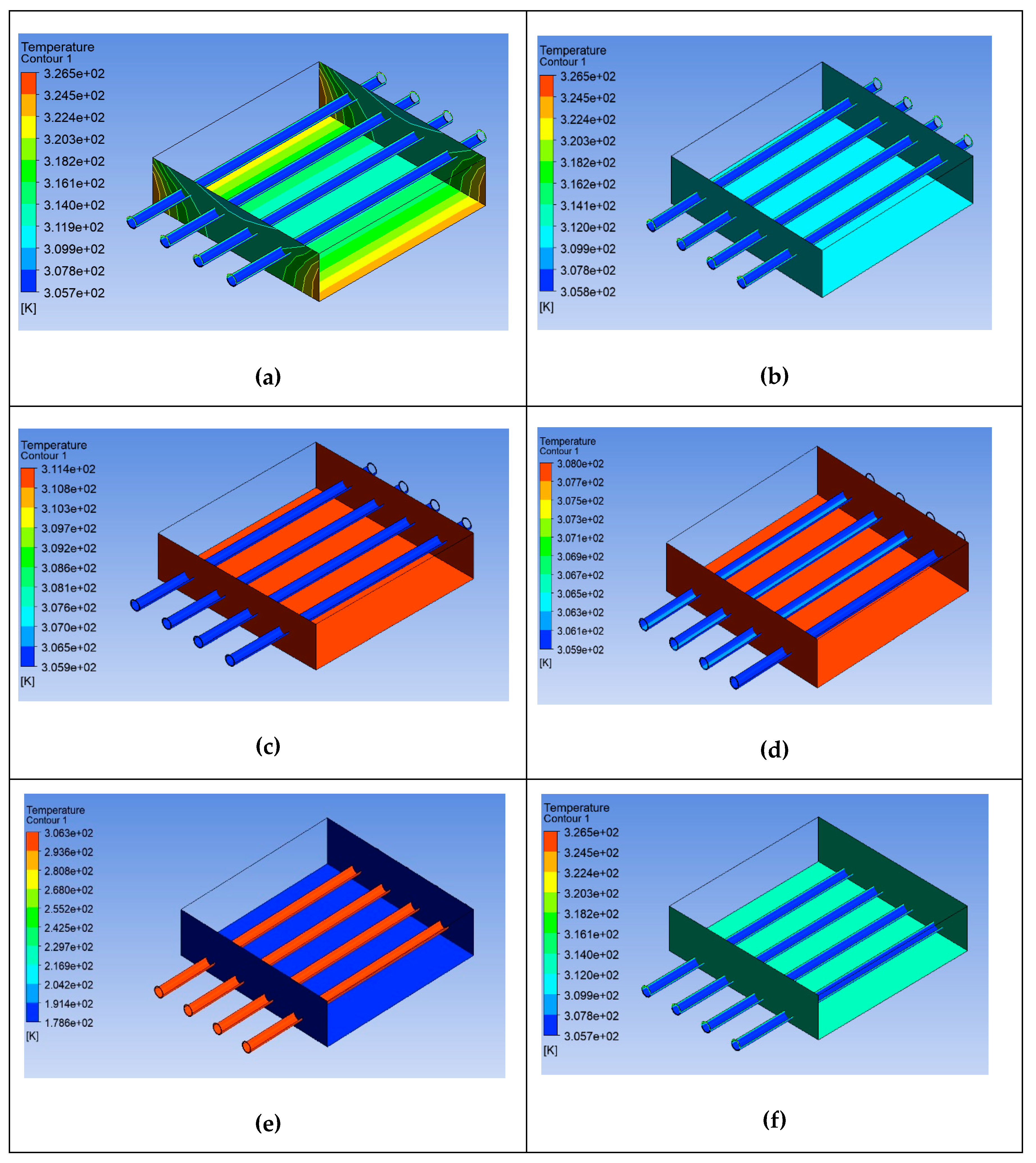
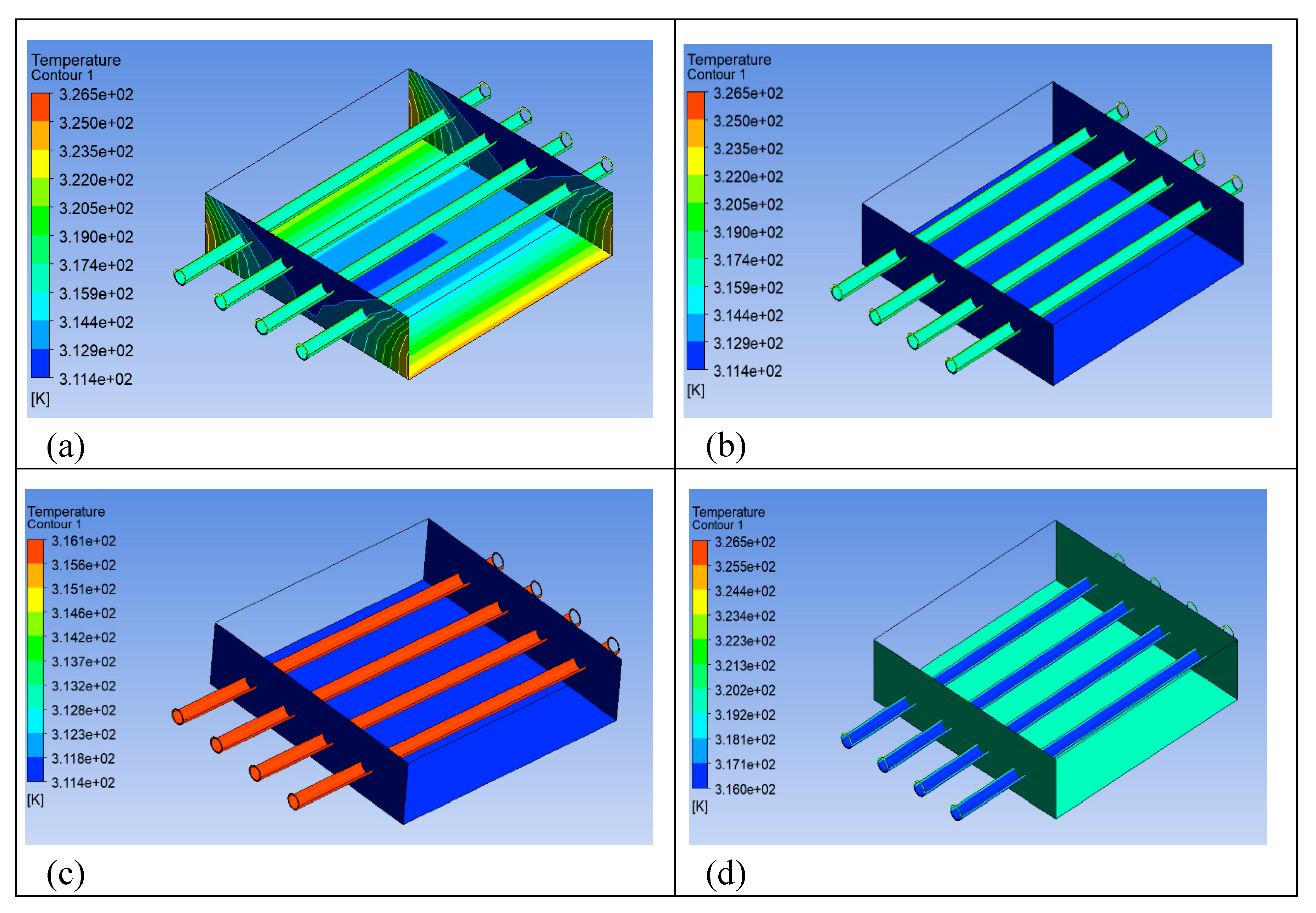
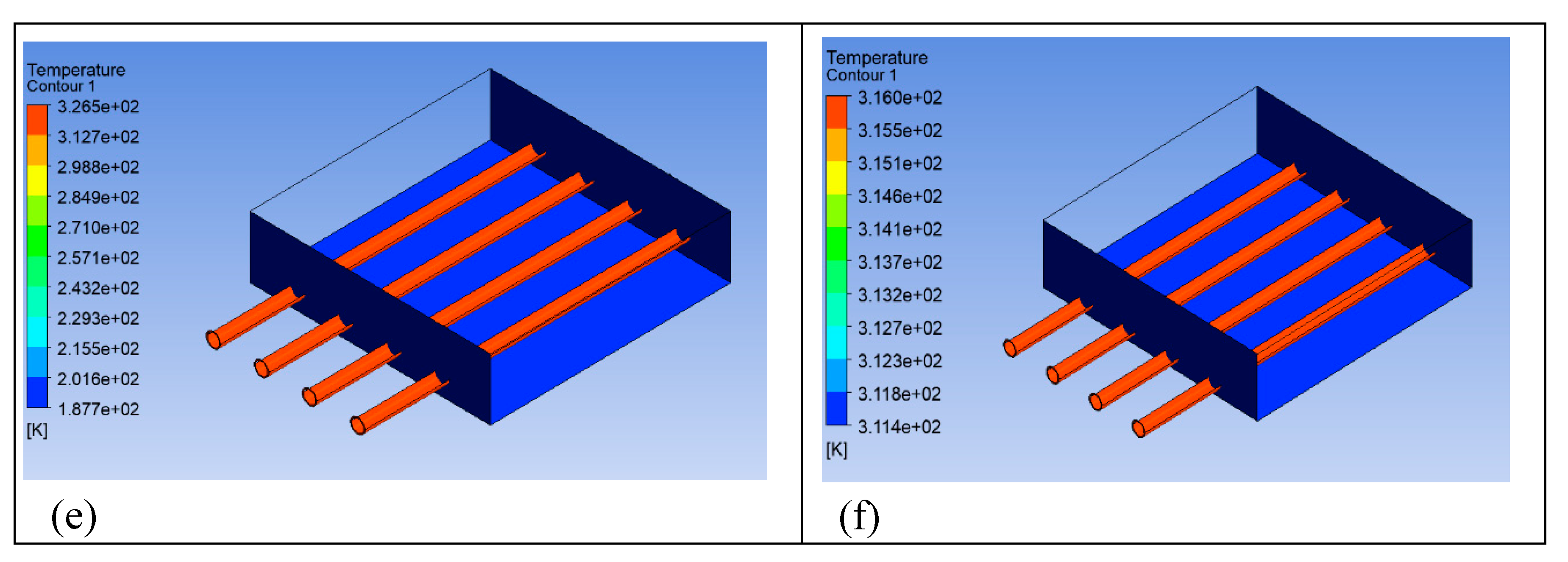
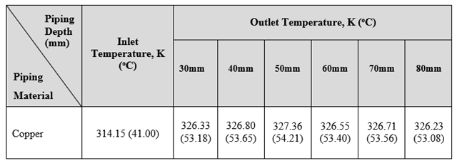
Figure 13 shows the relationship between inserted copper pipe depth from 30mm until 80mm from the top of the surface pavement against the temperature distribution, while Table 4 sums the inlet and outlet temperature for all copper piping depths (30mm, 40mm, 50mm, 60mm, 70mm, and 80mm). As can be seen from Figure 13(c), the copper pipes at depth 50mm show the highest temperature output from outlet pipe which is 327.36K (54.21oC), with the lowest temperature of 326.23 (53.08oC) obtained from piping depth at 80mm (Figure 13(f)). This agrees from previous research whom found that the serpentine arrangement copper pipes embedded in asphalt pavement collected the maximum temperature of 53.5oC from outlet pipe at depth of 50mm [14]. This is due to the fact that the maximum solar energy is collected in upper part until at the center depth of the asphalt pavement, while lower part collects less solar energy.

3.1.2. Piping Depth for Stainless Steel Pipes

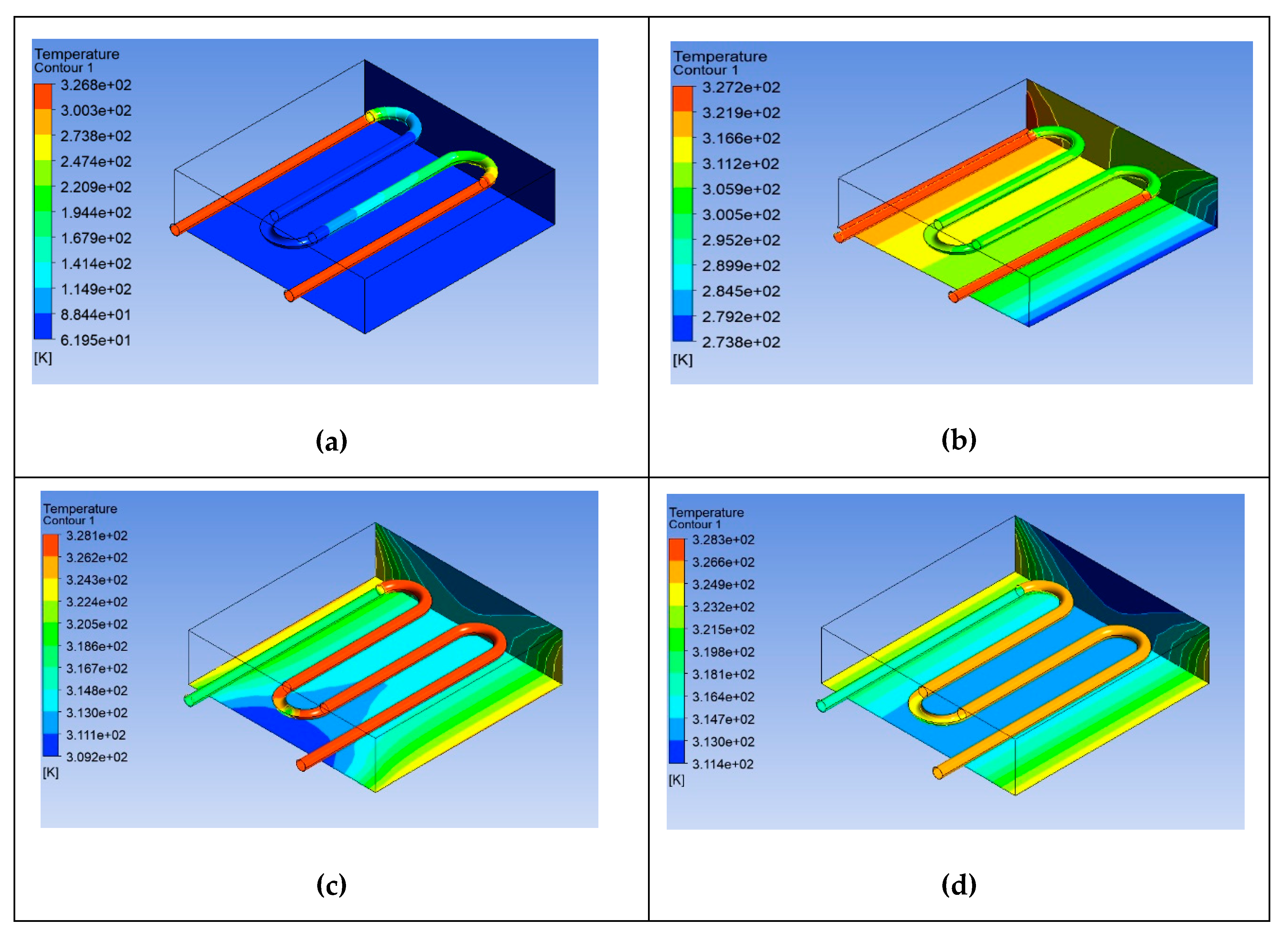
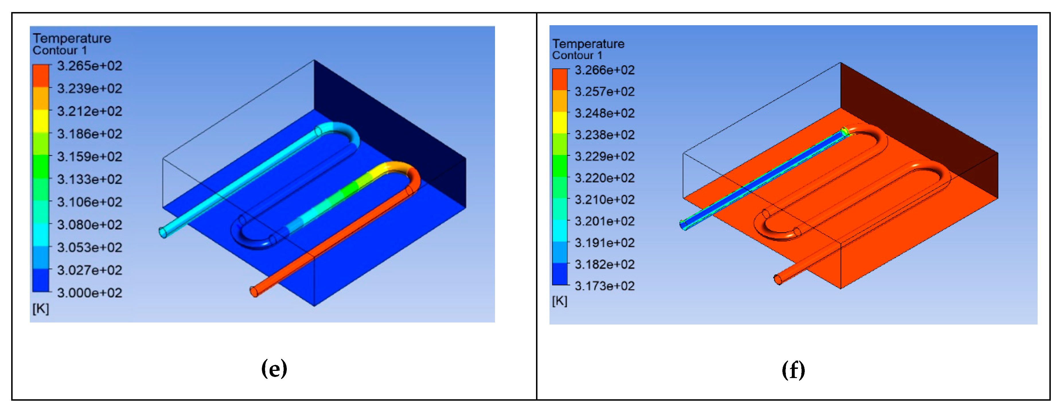
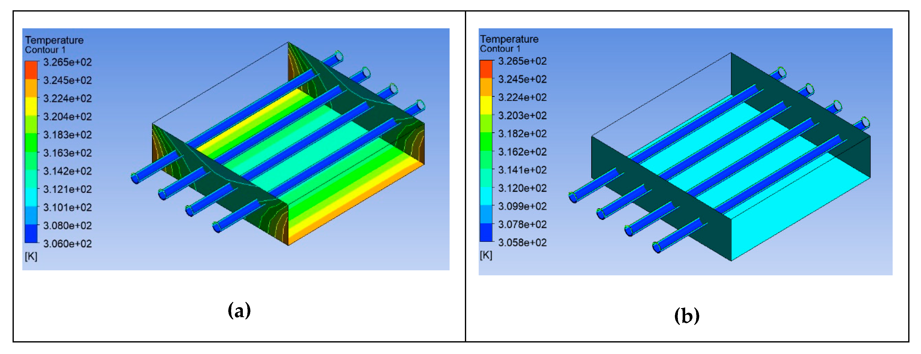
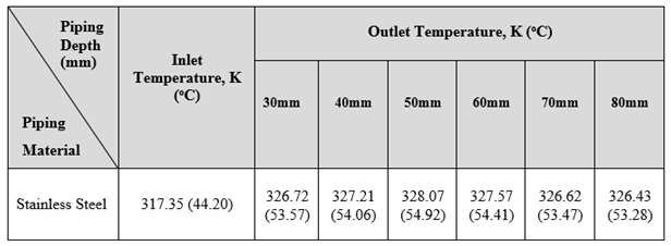
Figure 14 shows the serpentine arrangement of stainless steel at 30mm until 80mm depths from the top of surface pavement. Table 5 sums the inlet and outlet temperature for all stainless steel piping depths (30mm, 40mm, 50mm, 60mm, 70mm, and 80mm). Similar to the copper piping, results show that the maximum heat extraction from the outlet pipe was 328.07K (54.92oC) at the pipe depth of 50mm (Figure 14(c)), while the minimum was 326.43K (53.28oC) at the depth of 80mm (Figure 14(f)). A field monitoring of six samples of asphalt slab with stainless steel pipe arranged at different depths of 50mm, 100mm, and 150mm show that the maximum heat extraction was at a depth 50mm which was 53.2°C [15]. A significant increase in temperature can be achieved if more heat is applied to the asphalt surface. As the asphalt pavement's ability to absorb radiant heat increases, it results an increase in heat accumulation in the thermal block.

3.1.3. Piping Depth for Aluminium Pipes

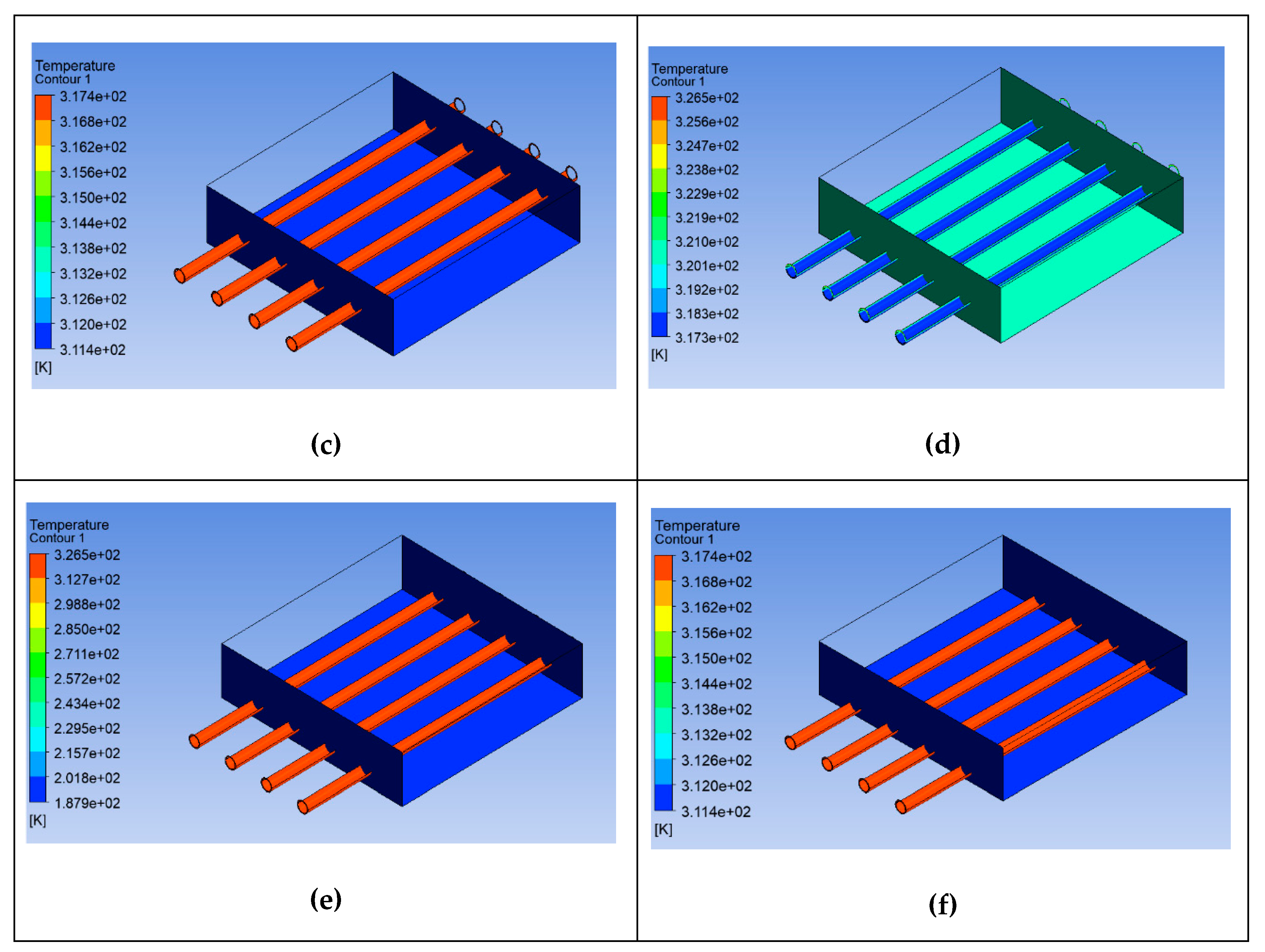
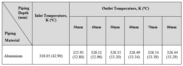
The serpentine arrangement of aluminum pipes was also tested and shown in Figure 15 with similar pipe depths to the copper and stainless steel pipes. Table 6 shows the inlet and outlet temperature for all aluminium piping depths (30mm, 40mm, 50mm, 60mm, 70mm, and 80mm). It can be seen in Figure 15(e), that the highest heat extraction from the outlet for aluminium pipe was 326.54K (53.39°C) at the depth of 70mm. The minimum temperature for aluminium was 325.95K (52.80oC) at the depth of 30mm (Figure 15(a)). The heated air exits through the aluminium pipe located at the center of the top channel of fabrication design model. The temperature of the incoming and exiting air was measured by thermocouple and it show the maximum outlet temperature was 55oC while the minimum outlet temperature was 42oC at the morning readings [16].

3.1.4. Comparison between Different Piping Materials and Depth for Serpentine Piping System

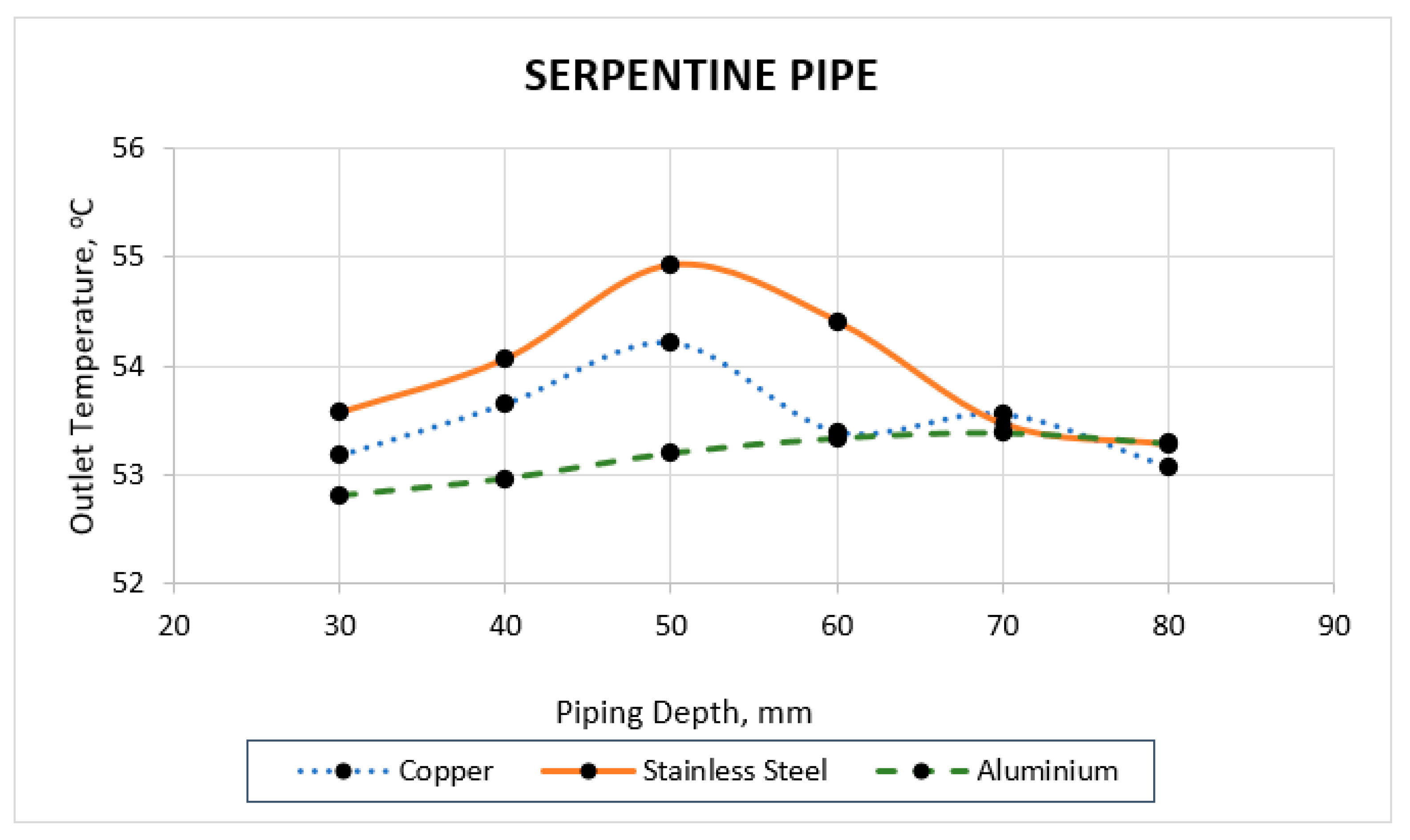
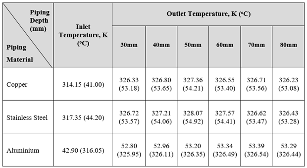
Table 7 shows the various types of piping materials (copper, stainless steel, and aluminium) and outlet temperatures for piping depths ranging from 30mm to 80mm, while Figure 4.4 presents the tabulated data for the temperature outlet for the serpentine piping system for various materials versus piping depth in graphical form. The graph shows an increasing temperature outlet at the middle piping depth and decreasing to the lowest piping depth for all types of material.
As can be seen from the figure, the aluminium pipe at depth 30mm shows the lowest outlet temperature at 325.95K (52.80oC), while the stainless steel pipe shows the highest outlet temperature as 328.07K (54.92oC) at depth 50mm. The results of using aluminium pipes shows the lowest temperature from outlet pipe at depth 50mm compared to copper and stainless steel pipes with temperatures of 327.36K (54.21oC) and 328.07K (54.92oC) respectively.

3.1.5. Comparison between Different Piping Depths and Heat Efficiency for Serpentine Piping System

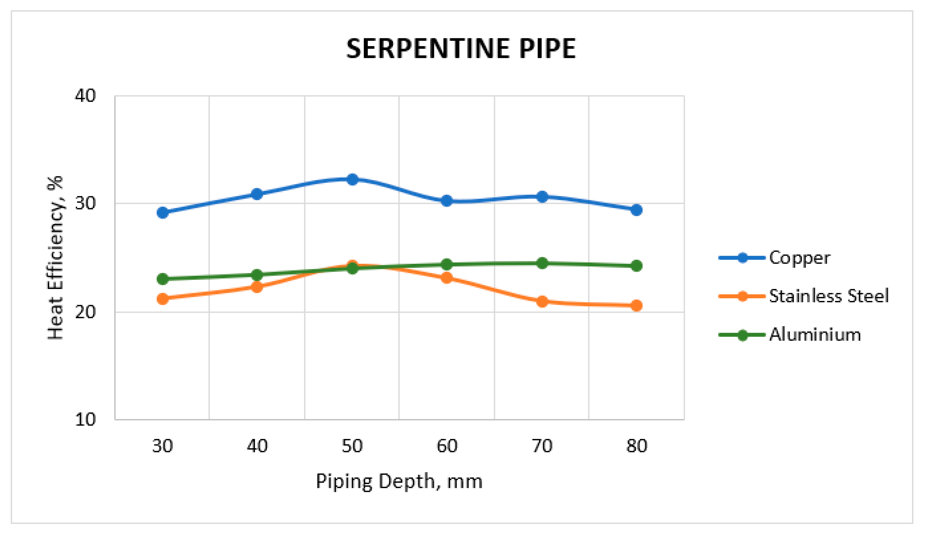
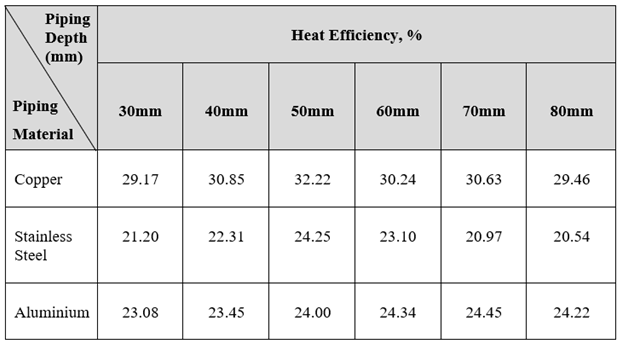
Table 8 shows the types of piping material and heat efficiency for each piping depth while Figure 17 represent in graphical from the tabulated data of serpentine pipe for heat efficiency versus piping depth. The highest heat efficiency was 32.22% from copper pipes at depth 50mm and the lowest was 20.54% from stainless steel pipe at depth 80mm. The efficiency of even the best heat is usually below than 50% [17]. Thus, in this research, copper pipe (at depth 50mm) was selected as piping material due to the highest value in heat efficiency. Furthermore, copper pipes are highly efficient conductors of heat. Using the liquid and gas phase, heat transfer is very efficient as the copper pipes work passively continuously, creating a highly reliable component in the thermal management system [18].

3.2. Optimization of the Thermal Energy Harvesting Series Piping System using Numerical Simulation

3.2.1. Piping Depth for Copper, Stainless Steel and Aluminium Piping

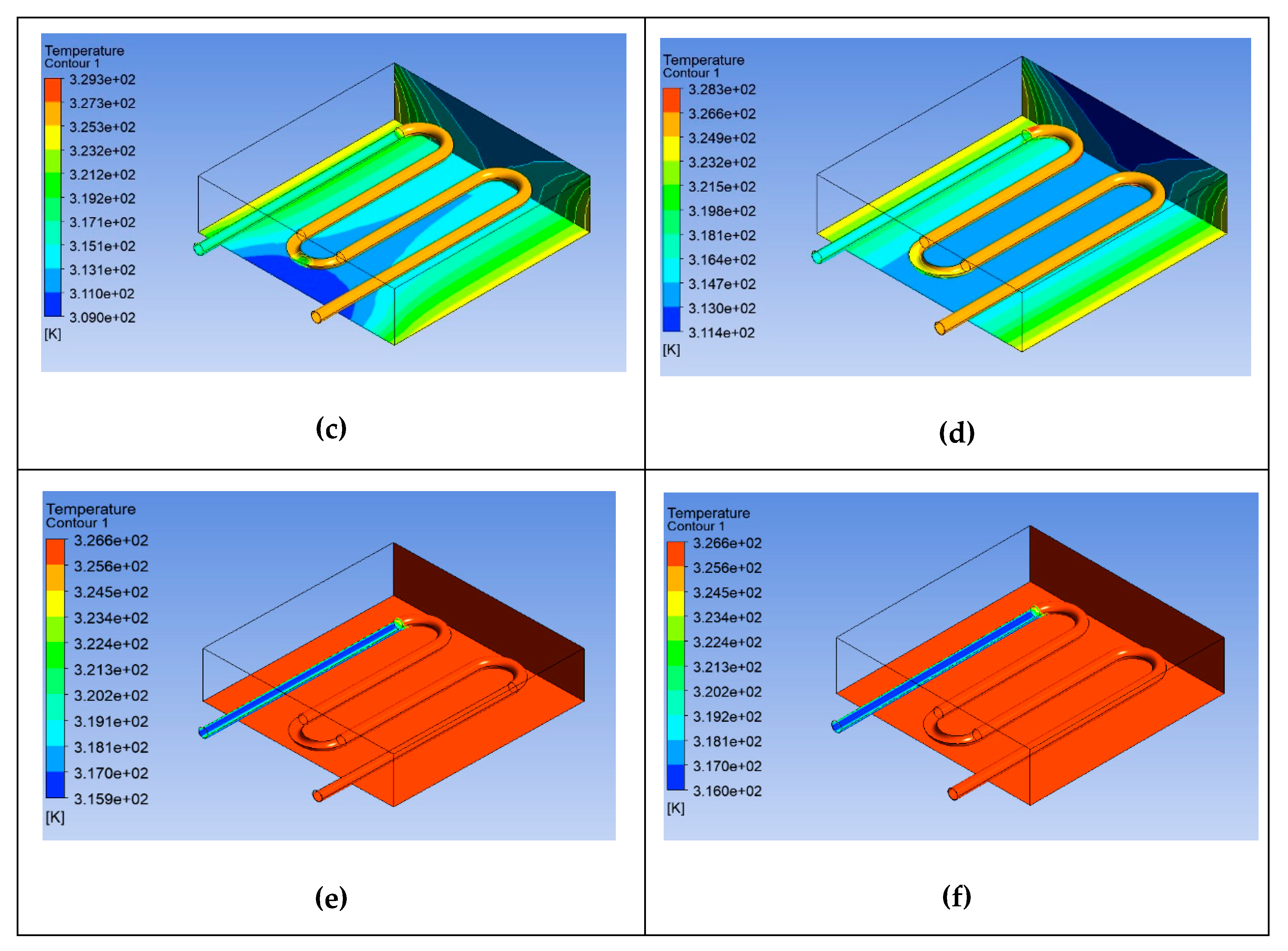
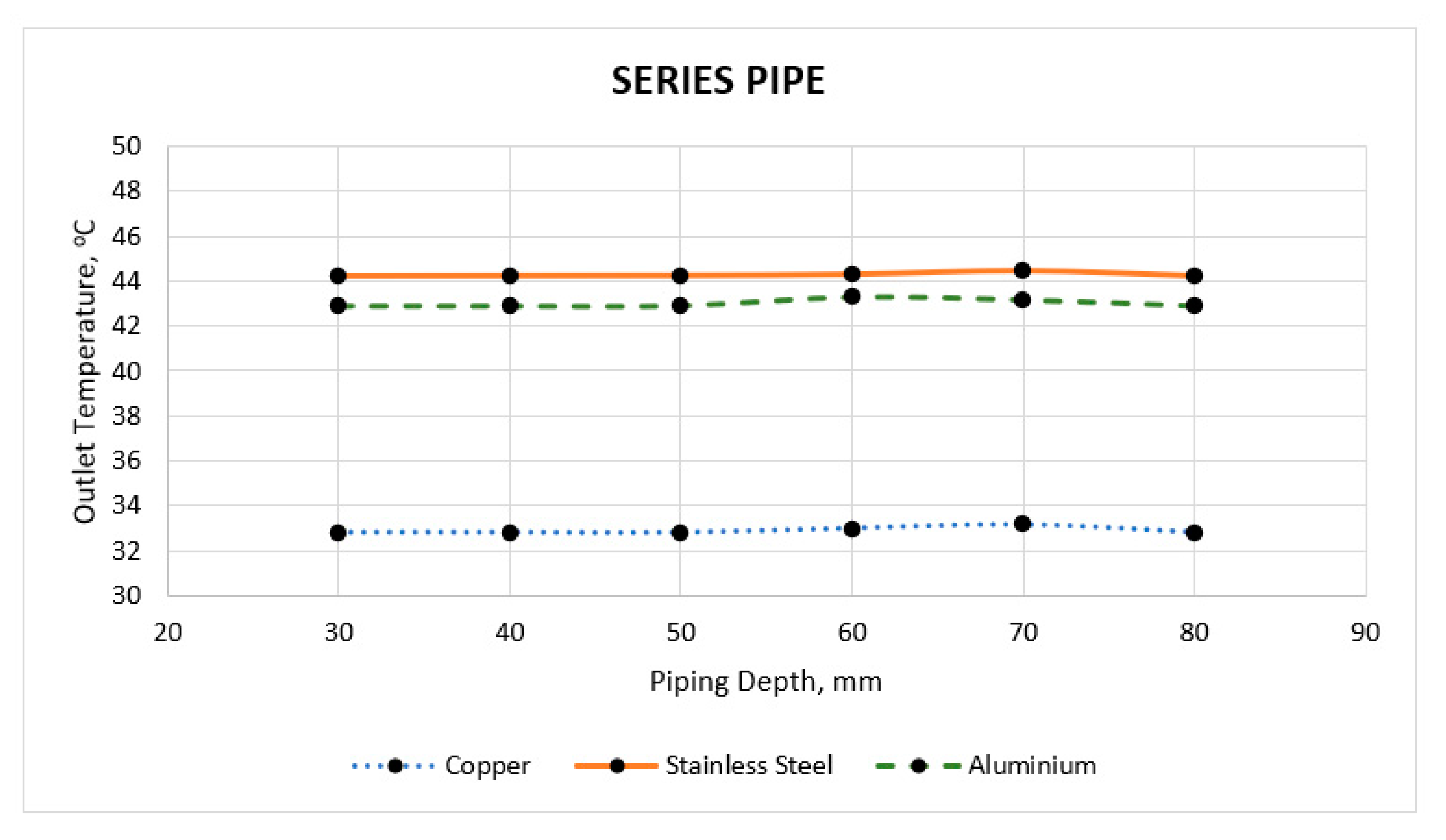
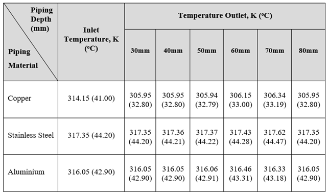
According to the findings of the literature review, there was not much information regarding series pipe. Therefore, the results and discussion were explained in this section. Figure 18 until Figure 20 shows the relationship between inserted copper, stainless steel, and aluminium pipe depth from 30mm until 80mm from the top of the surface pavement against the temperature distribution. Stainless steel pipes obtained the highest heat extraction from outlet pipe which was 317.62K (44.47oC) at depth 70mm while the lowest heat extraction occurred at copper pipe with the temperature outlet as 305.94K (32.79oC) at depth 50mm. The others researchers explained that in the series configuration, the flow rate is uniform through the circulation path [19]. So, the values of outlet temperature were slightly same to the inlet temperatures. As seen, the pipe configuration can significantly affect the heat temperature at the outlet terminal of the pavement solar collector. Based on the explanation for serpentine pipe and comparison with series pipe, serpentine pipe was chosen as the arrangement of piping. Table 9 sums the inlet and outlet temperature for all piping material depths (30mm, 40mm, 50mm, 60mm, 70mm, and 80mm).
Figure 21 presents the tabulated data for the temperature outlet for the series piping system for various materials versus piping depth in graphical form. The data refer from Table 9 and it shows the highest temperature outlet for each depth from stainless steel pipe and lowest temperature outlet from copper pipe. Pipelines are one of the cheapest means of transporting liquids. They are widely used for transporting water, fuel and other substances but by using the series pipe, the temperature at the end of outlet pipe was similarly same as inlet temperature except for copper pipe. This is because the major loss coefficients in series copper pipe have been occurred. The head loss coefficients (for local losses, fittings and valves) and friction coefficients (for distributed losses throughout the pipe)especially in the friction of internal pipe wall [20]. Compared to serpentine pipe, there was no value for heat efficiency for series pipe because the value was achieve more than 50% while the best heat efficiency is usually below than 50% [17]. So, from the comparison of serpentine and series pipe, the chosen arrangement of piping was serpentine because of highest temperature outlet (54.21oC from copper pipe at depth 50mm and 44.47oC from stainless steel pipe at depth 70mm respectively) and acceptable on the heat efficiency compared to series pipe.

3.3. Piping Spacing

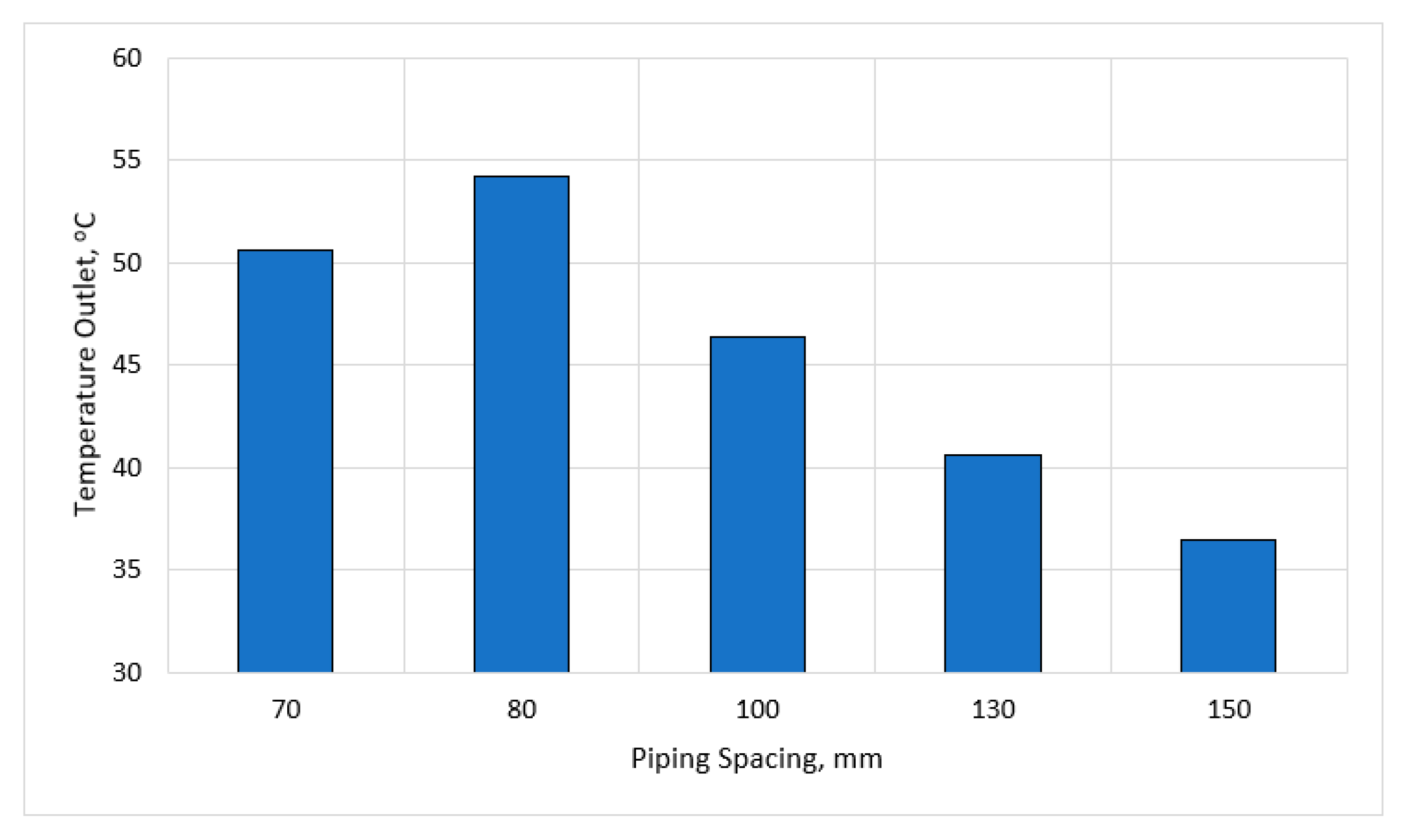
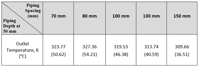
Based on the previous section, section 3.1. and 3.2. was verified serpentine copper pipe at depth 50mm as optimum heat extraction from outlet pipe. In this section, the pipe spacing from centre-to-centre with dimension 70mm, 80mm, 100mm, 130mm and 150mm was tested to get the optimum heat extraction from outlet pipe. Table 10 and Figure 22 shows the data and graphical patterns of the piping spacing and temperature outlet for serpentine copper pipes at depth 50mm. Serpentine copper pipes at depth 50mm was selected to analyse through the optimal piping spacing because its reach the highest heat efficiency from previous simulation works. So, from the results, the optimum piping spacing was 80mm and temperature outlet was 327.36K (54.21oC). The distance between the heating pipes was found to be an important factor affecting the total heat loss and the actual heat exchange between the pipes in the new multi-control heating system [21]. On-site experimental for the thermal performance of pavement solar collectors, the importance of pipe spacing as the model can interact with simulation environments, heat sources, and heat pump for real-time automation [22].

3.4. Types of Material

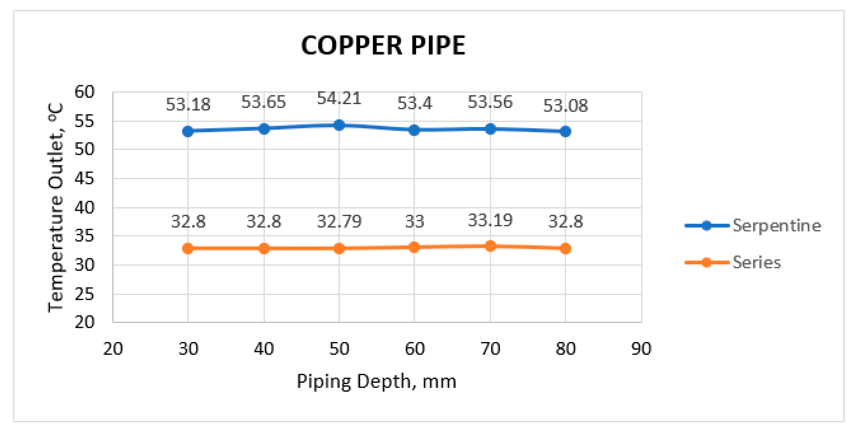
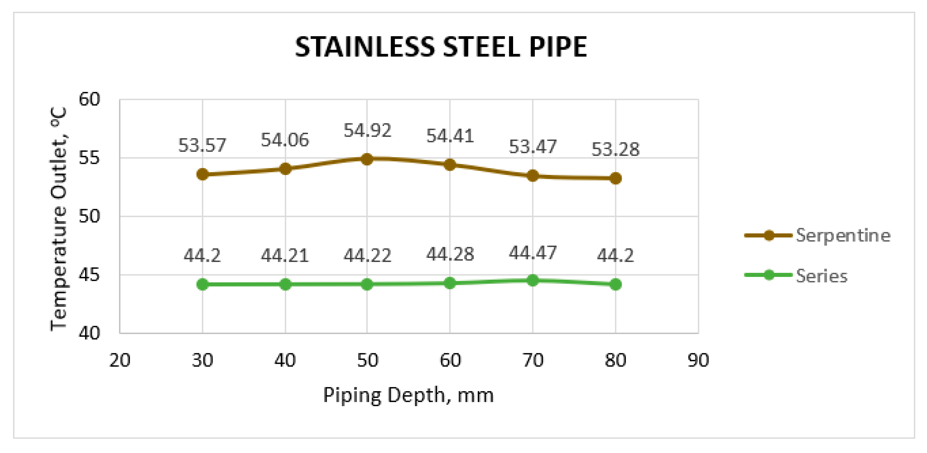
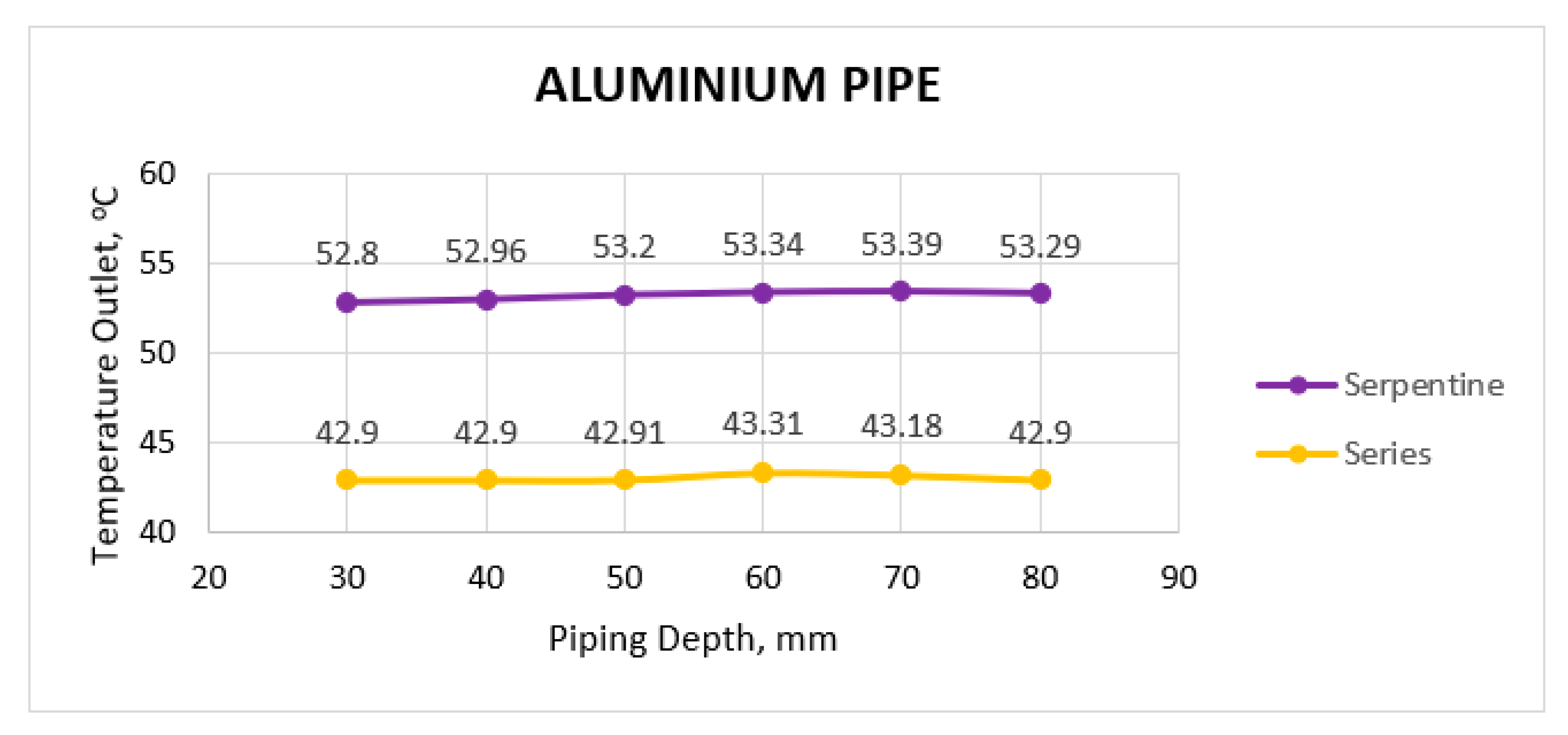
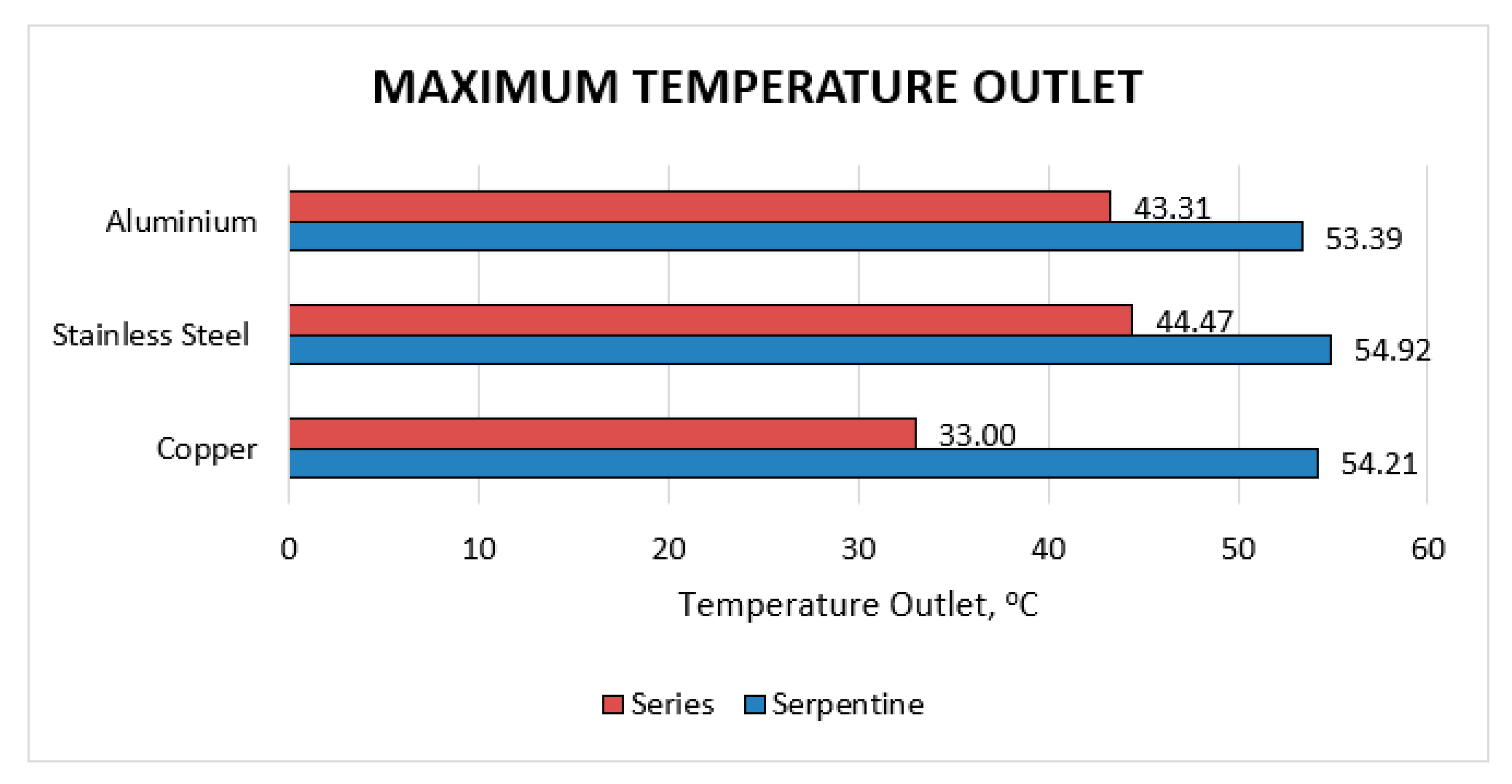
Based on past studies mentioned in introduction part, the selected material was stated as sustainable conductive material. Figure 23 until Figure 25 shows the comparison of temperature outlet by serpentine and series pipes for copper, stainless steel, and aluminium respectively. The graph presents that serpentine pipe show the highest temperature outlet than series pipe for all piping material. Even though stainless steel pipe was shows the highest temperature than other material, the selected material for this research was copper. Stainless steel is used in many industries because of its excellent corrosion resistance, ease of formability and weldability. However, their low hardness, poor tribological properties and potential for localized corrosion in certain environments may limit their use [23]. As per Figure 26, it shows the comparison maximum values of temperature outlet for both piping arrangements.

3.5. Flow Rate

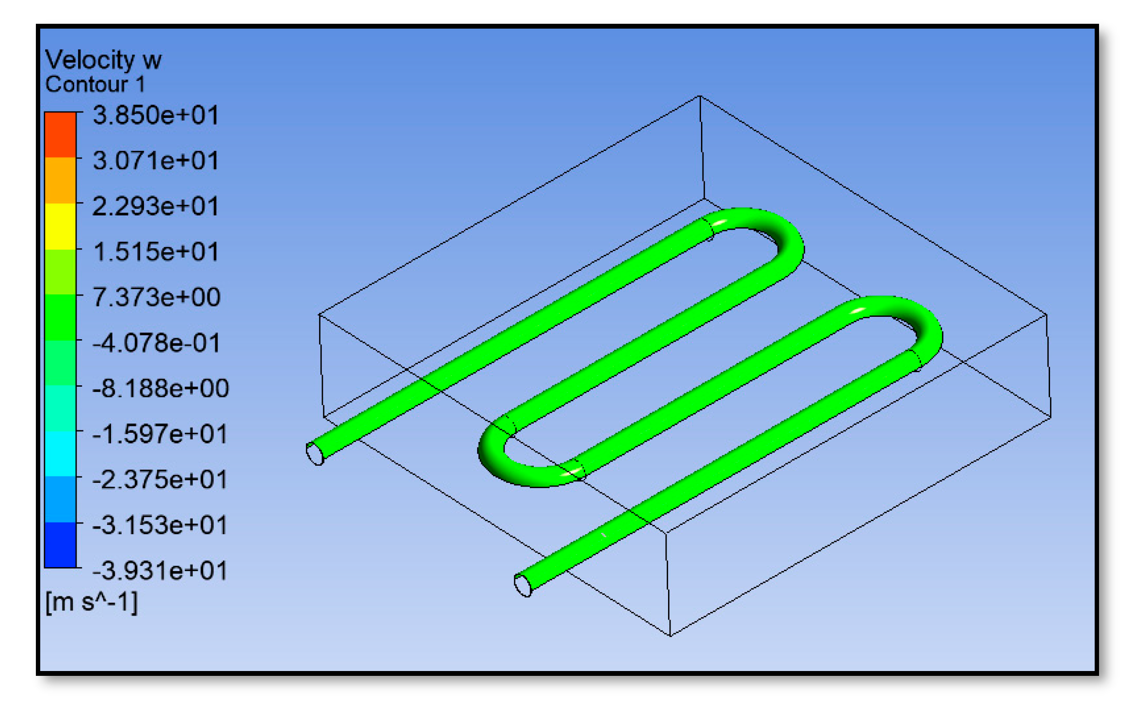
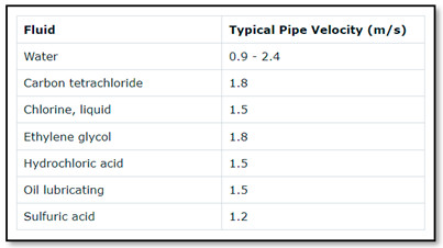
Figure 27 shows the uniformly flow rate prepared using Ansys Workbench 19.2 (Fluent) for model dimension 400 mm x 400 mm x 100 mm. The serpentine copper pipe was located at the middle (50mm) of model depth. The velocity at the inlet pipe was set to 0.0409m/s [13] followed by the peak flow or known as domestic flow water reticulation residential landed houses. It is calculated for water distribution for domestic uses (residential, school, commercial etc.). From the results, the velocity at the outlet pipe was 1.562m/s with respect to the outlet temperature as 327.36K (54.21oC). For water-like liquids with no entrained solids a pipe velocity of about 1 to 2m/s is considered an acceptable value [24]. Table 11 shows the following lists some of typical pipe velocities for a range of common industrial feeds.

4. Conclusions

The pipe material tested in this research are copper, stainless steel, and aluminium because of these pipes is categorized as sustainable conductive piping. The pipes are inserted with water stagnant flow in the various depth which are 30mm, 40mm, 50mm, 60mm, 70mm, and 80mm from the surface pavement. The pipe spacing between center-to-center were also tested at various spacing which are 70mm, 80mm, 100mm, 130mm, and 150mm. In conclusion, the pipe material chosen is copper, pipe depth at 50mm from surface pavement with the pipe arrangement is serpentine, pipe spacing is 80mm and water flow rate is 1.562m/s. The velocity flow rate from optimized thermal energy extraction of water reticulation landed residential houses was 1.562m/s by the outlet temperature was 327.36K (54.21oC) for solar pavement types was serpentine copper pipe inserted at the middle of the research prototype depth. The velocity is depending on the water flow rate set at inlet pipe as 0.0409 m/s for peak flow water demand.

Author Contributions

Writing—original draft preparation, Nurul Aqilah Razeman; supervision, Zarina Itam and Salmia Beddu; investigation, Daud Mohammad and Nazirul Mubin Zahari; methodology, Agusril Syamsir and Nur Liyana Mohd Kamal; validation, Mohd Hafiz Zawawi and Norizham Abdul Razak. All authors have read and agreed to the published version of the manuscript.

Funding

This publication was funded UNITEN BOLD Refresh with support from FRGS 2020-1 Grant No. FRGS/1/2020/TK0/UNITEN/02/18.

Data Availability Statement

Data available in a publicly accessible repository that does not issue DOIs.

Acknowledgments

The authors are grateful to acknowledge IRMC UNITEN and Universiti Tenaga Nasional (UNITEN) for the laboratory facilities.

Conflicts of Interest

The authors declare no conflict of interest.

References

  1. J. D. Sachs, G. Schmidt-Traub, M. Mazzucato, D. Messner, N. Nakicenovic, and J. Rockström, ‘Six Transformations to achieve the Sustainable Development Goals’, Nat. Sustain., vol. 2, no. 9, p. n/a-n/a, Aug. 2019. [CrossRef]
  2. M. S. Norouzzadeh et al., ‘Automatically identifying, counting, and describing wild animals in camera-trap images with deep learning’, Proc. Natl. Acad. Sci. U. S. A., vol. 115, no. 25, pp. E5716–E5725, Jun. 2018. [CrossRef]
  3. F. Fuso Nerini et al., ‘Connecting climate action with other Sustainable Development Goals’, Nat. Sustain. 2019 28, vol. 2, no. 8, pp. 674–680, Jul. 2019. [CrossRef]
  4. F. F. Nerini, A. Slob, R. E. Engström, and E. Trutnevyte, ‘A Research and Innovation Agenda for Zero-Emission European Cities’, Sustain. 2019, Vol. 11, Page 1692, vol. 11, no. 6, p. 1692, Mar. 2019. [CrossRef]
  5. R. Kwok, ‘AI empowers conservation biology’, Nature, vol. 567, no. 7746, pp. 133–135, Mar. 2019, Accessed: Dec. 13, 2022. [Online]. Available: https://go.gale.com/ps/i.do?p=HRCA&sw=w&issn=00280836&v=2.1&it=r&id=GALE%7CA577073479&sid=googleScholar&linkaccess=fulltext.
  6. W. S. Alaloul, M. Altaf, M. A. Musarat, M. F. Javed, and A. Mosavi, ‘Systematic Review of Life Cycle Assessment and Life Cycle Cost Analysis for Pavement and a Case Study’, Sustain. 2021, Vol. 13, Page 4377, vol. 13, no. 8, p. 4377, Apr. 2021. [CrossRef]
  7. S. Mundada, Y. Nilsiam, and J. M. Pearce, ‘A review of technical requirements for plug-and-play solar photovoltaic microinverter systems in the United States’, Sol. Energy, vol. 135, pp. 455–470, Oct. 2016. [CrossRef]
  8. V. Bobes-Jesus, P. Pascual-Muñoz, D. Castro-Fresno, and J. Rodriguez-Hernandez, ‘Asphalt solar collectors: A literature review’, Appl. Energy, vol. 102, pp. 962–970, Feb. 2013. [CrossRef]
  9. D. Vizzari, E. Gennesseaux, S. Lavaud, S. Bouron, and E. Chailleux, ‘Pavement energy harvesting technologies: a critical review’, RILEM Tech. Lett., vol. 6, pp. 93–104, Aug. 2021. [CrossRef]
  10. García and M. N. Partl, ‘How to transform an asphalt concrete pavement into a solar turbine’, Appl. Energy, vol. 119, pp. 431–437, Apr. 2014. [CrossRef]
  11. Chiarelli, A. R. Dawson, and A. García, ‘Parametric analysis of energy harvesting pavements operated by air convection’, Appl. Energy, vol. 154, pp. 951–958, Sep. 2015. [CrossRef]
  12. R. Mirzanamadi, P. Johansson, and S. A. Grammatikos, ‘Thermal properties of asphalt concrete: A numerical and experimental study’, Constr. Build. Mater., vol. 158, pp. 774–785, Jan. 2018. [CrossRef]
  13. ‘Water Reticulation Benchmark - MES Innovation Sdn Bhd’. https://mes100.com/docs/water-reticulation-benchmark/ (accessed Nov. 29, 2022).
  14. ‘Ground Source Energy | District Heating | Heat Networks | Clean Heating | Sustainable Energy | Renewable Energy | Ground source heating | Heat Pumps | Ground source cooling’. https://www.icax.co.uk/ (accessed Apr. 27, 2022).
  15. S. H. A. Talib, S. I. N. Syed Hashim, S. Beddu, A. F. Maidin, and M. S. Abustan, ‘Heat Lump in Different Pavement Layer Using Ethylene Glycol as A Solar Heat Collector’, in MATEC Web of Conferences, Dec. 2016, vol. 87, p. 01015. [CrossRef]
  16. P. Mohamed Shameer and P. Mohamed Nishath, ‘Designing and Fabrication of Double Pass Solar Air Heater Integrated With Thermal Storage’, Int. J. Sci. Res., vol. 4, no. 1, pp. 1909–1914, 2015.
  17. P. Pietzonka and U. Seifert, ‘Universal Trade-Off between Power, Efficiency, and Constancy in Steady-State Heat Engines’, Phys. Rev. Lett., vol. 120, no. 19, p. 190602, May 2018. 20 May. [CrossRef]
  18. ‘What is a Heat Pipe | Heat Pipes Basics and Technology’. https://www.1-act.com/resources/heat-pipe-fundamentals/ (accessed Dec. 03, 2022).
  19. E. H. Zaim, H. Farzan, and M. Ameri, ‘Assessment of pipe configurations on heat dynamics and performance of pavement solar collectors: An experimental and numerical study’, Sustain. Energy Technol. Assessments, vol. 37, p. 100635, Feb. 2020. [CrossRef]
  20. Santos-Ruiz, F.-R. López-Estrada, V. Puig, and G. Valencia-Palomo, ‘Simultaneous Optimal Estimation of Roughness and Minor Loss Coefficients in a Pipeline’, Math. Comput. Appl., vol. 25, no. 3, p. 56, 2020. [CrossRef]
  21. Q. Xu et al., ‘A new type of two-supply, one-return, triple pipe-structured heat loss model based on a low temperature district heating system’, Energy, vol. 218, p. 119569, Mar. 2021. [CrossRef]
  22. T. Ghalandari et al., ‘A simplified model to assess the thermal performance of pavement solar collectors’, Appl. Therm. Eng., vol. 197, p. 117400, Oct. 2021. [CrossRef]
  23. F. Borgioli, ‘From Austenitic Stainless Steel to Expanded Austenite-S Phase: Formation, Characteristics and Properties of an Elusive Metastable Phase’, Met. 2020, Vol. 10, Page 187, vol. 10, no. 2, p. 187, Jan. 2020. [CrossRef]
  24. ‘Useful information on pipe velocity’. https://www.michael-smith-engineers.co.uk/resources/useful-info/pipe-velocity (accessed Nov. 29, 2022).
Figure 1. Process of flow optimization of thermal energy harvesting.
Preprints 78353 g001
Figure 2. Serpentine pipe and the piping material replaced by stainless steel, copper, and aluminium.
Preprints 78353 g002
Figure 3. Serpentine pipe and the piping material replaced by stainless steel, copper, and aluminium.
Preprints 78353 g003
Figure 4. Serpentine pipe.
Preprints 78353 g004
Figure 5. Meshing model for inserted serpentine piping.
Preprints 78353 g005
Figure 6. Series pipe.
Preprints 78353 g006
Figure 7. Meshing model for inserted series piping.
Preprints 78353 g007
Figure 13. Various serpentine copper piping depth from the pavement surface: (a) 30mm, (b) 40mm, (c) 50mm, (d) 60mm, (e) 70mm, and (f) 80mm.
Preprints 78353 g013
Figure 14. Various serpentine stainless steel piping depth from the pavement surface: (a) 30mm, (b) 40mm, (c) 50mm, (d) 60mm, (e) 70mm, and (f) 80mm.
Preprints 78353 g014aPreprints 78353 g014b
Figure 15. Various serpentine aluminium piping depth from the pavement surface: (a) 30mm, (b) 40mm, (c) 50mm, (d) 60mm, (e) 70mm, and (f) 80mm.
Preprints 78353 g015aPreprints 78353 g015b
Figure 16. Serpentine pipe temperature outlet for various materials versus different piping depths.
Preprints 78353 g016
Figure 17. Serpentine pipe heat efficiency versus piping depth.
Preprints 78353 g017
Figure 18. Various series copper piping depth from the pavement surface: (a) 30mm, (b) 40mm, (c) 50mm, (d) 60mm, (e) 70mm, and (f) 80mm.
Preprints 78353 g018
Figure 19. Various series stainless steel piping depth from the pavement surface: (a) 30mm, (b) 40mm, (c) 50mm, (d) 60mm, (e) 70mm, and (f) 80mm.
Preprints 78353 g019aPreprints 78353 g019b
Figure 20. Various series aluminium piping depth from the pavement surface: (a) 30mm, (b) 40mm, (c) 50mm, (d) 60mm, (e) 70mm, and (f) 80mm.
Preprints 78353 g020aPreprints 78353 g020b
Figure 21. Series pipe temperature outlet for various materials versus different piping depths.
Preprints 78353 g021
Figure 22. Temperature outlet versus piping spacing for serpentine piping.
Preprints 78353 g022
Figure 23. The comparison of temperature outlet for copper pipe.
Preprints 78353 g023
Figure 24. The comparison of temperature outlet for stainless steel pipe.
Preprints 78353 g024
Figure 25. The comparison of temperature outlet for aluminium pipe.
Preprints 78353 g025
Figure 26. The comparison maximum values of temperature outlet.
Preprints 78353 g026
Figure 27. Uniform flow rate.
Preprints 78353 g027
Table 1. Inlet Temperature for all piping material.
Piping Material Inlet Temperature, K (oC)
Copper 314.15 (41.00)
Stainless Steel 317.35 (44.20)
Aluminium 42.90 (316.05)
Table 2. Thermal properties of asphalt concrete [12].
Bulk Density (kg/m3) Thermal Conductivity (W/m.K) Specific Heat Capacity (J/kg/K)
2297.17 2.19 782.04
Table 3. Velocity of domestic flow [13].
Types of Flow Velocity (m/s)
Normal flow 0.0205
Peak flow 0.0409
Table 4. Outlet temperature against piping depth.
Preprints 78353 i001
Table 5. Outlet temperature against piping depth.
Preprints 78353 i002
Table 6. Outlet temperature against piping depth.
Preprints 78353 i003
Table 7. Various materials with outlet temperature for different piping depths.
Preprints 78353 i004
Table 8. Heat efficiency for various materials at different piping depths.
Preprints 78353 i005
Table 9. Outlet temperature against piping depth.
Preprints 78353 i006
Table 10. Temperature outlet for difference piping spacing.
Preprints 78353 i007
Table 11. Typical pipe velocities.
Preprints 78353 i008
Disclaimer/Publisher’s Note: The statements, opinions and data contained in all publications are solely those of the individual author(s) and contributor(s) and not of MDPI and/or the editor(s). MDPI and/or the editor(s) disclaim responsibility for any injury to people or property resulting from any ideas, methods, instructions or products referred to in the content.
Copyright: This open access article is published under a Creative Commons CC BY 4.0 license, which permit the free download, distribution, and reuse, provided that the author and preprint are cited in any reuse.
Prerpints.org logo

Preprints.org is a free preprint server supported by MDPI in Basel, Switzerland.

Subscribe

© 2024 MDPI (Basel, Switzerland) unless otherwise stated