1. Introduction
Some composite materials that can be utilized as sensor materials are piezoelectric composite materials [
1], conductive polymer materials [
2], bimetals [
3], and others. The first two are materials that combine the advantages of both organic and inorganic materials in a matrix. The others are used in temperature sensors, and others devices, by combining dissimilar metals. In addition, for engineering sensors, using materials such as new metal materials (e.g., liquid metal), high-performance polymer materials, fine ceramics, composite materials based on additive manufacturing, and others combined with electronics and biotechnology, may be able to meet various needs in the 21st century. They are expected to be used in cutting-edge technologies that supporting a variety of industries and economies [
4,
5]. Examples include robotics, wearable electronics [
6], epidermal electronic systems [
7], human-machine interfaces [
8], soft robotics [
9], other biomedical devices [
10,
11], and related systems [
12]. In most of these systems, sensory feedback plays an important role in considering efficiency and performance accuracy. Tactile sensors currently in use include pressure [
13], strain [
14], shear [
15], force [
16,
17] and vibration sensors [
18]. Through contact between objects and their sensors,human contact perception can be emulated in robots, and other machines. Common transduction principles used in this type of sensor include piezoresistive, piezocapacitive, piezoelectric, and triboelectric [
19]. However, those materials are hard, and their mechanical flexibility and stretchability need to be improved.
One of the goals of the experiments was to increase the finger's pressure sensitivity more sensitive and measure even smaller values. Additionally, the development of a DE stretch sensor with greater stretchability and flexibility using single-walled carbon nanotube (SWCNT) electrodes and this HNBR was attempted, in order to significantly improve the mechanical flexibility and stretchability of the DE sensors. Furthermore, using this stretch sensor, an experiment to sense the movement of the robot's finger and detect the force (pressure) when the fingertip touched the target object with the DE pressure sensor was tried. An experiment using a small diaphragm-type transducer DE actuator to confirm that the sensation of a robot finger touching an object can be fed back to a human finger was also conducted.
2. Background of Dielectric Elastomers
Dielectric elastomer (DE) was developed starting in 1991 by S. Chiba, R. Pelrine et al. at the Stanford Research Institute (SRI International, USA) [
20,
21]. The DE can be an actuator, a sensor and a generator with the same structure [
22]. Chiba et al. demonstrated that a 0.15 g DE could lift an 8 kgf weight by more than 1 mm in 88 ms, and they also demonstrated the great potential of ultra-lightweight and ultra-high performance DE motors [
22,
23]. They also developed a portable DE generator and showed that it is possible to charge a secondary battery at the same time [
24].
The development of artificial muscles by chemical approaches began in 1949 with actuators that depended on the movement of ions in polymer gels [
25,
26]. Actuators using ionic polymer-metal composites or conducting polymers utilize force by electrically transferring ions within the polymers [
27,
28]. In addition, actuators utilizing carbon nanotubes (CNT), heat, light, liquid crystal, air, and shape memory alloys are currently in development [
29,
30,
31,
32,
33,
34,
35,
36]. However, since it is superior in terms of performance, DE is becoming the mainstream. Piezo elements can generate a large force to some extent, and so actuators using piezo elements are in development. However, the element itself is hard and stretches little, so it is hard to call it a muscle [
37].
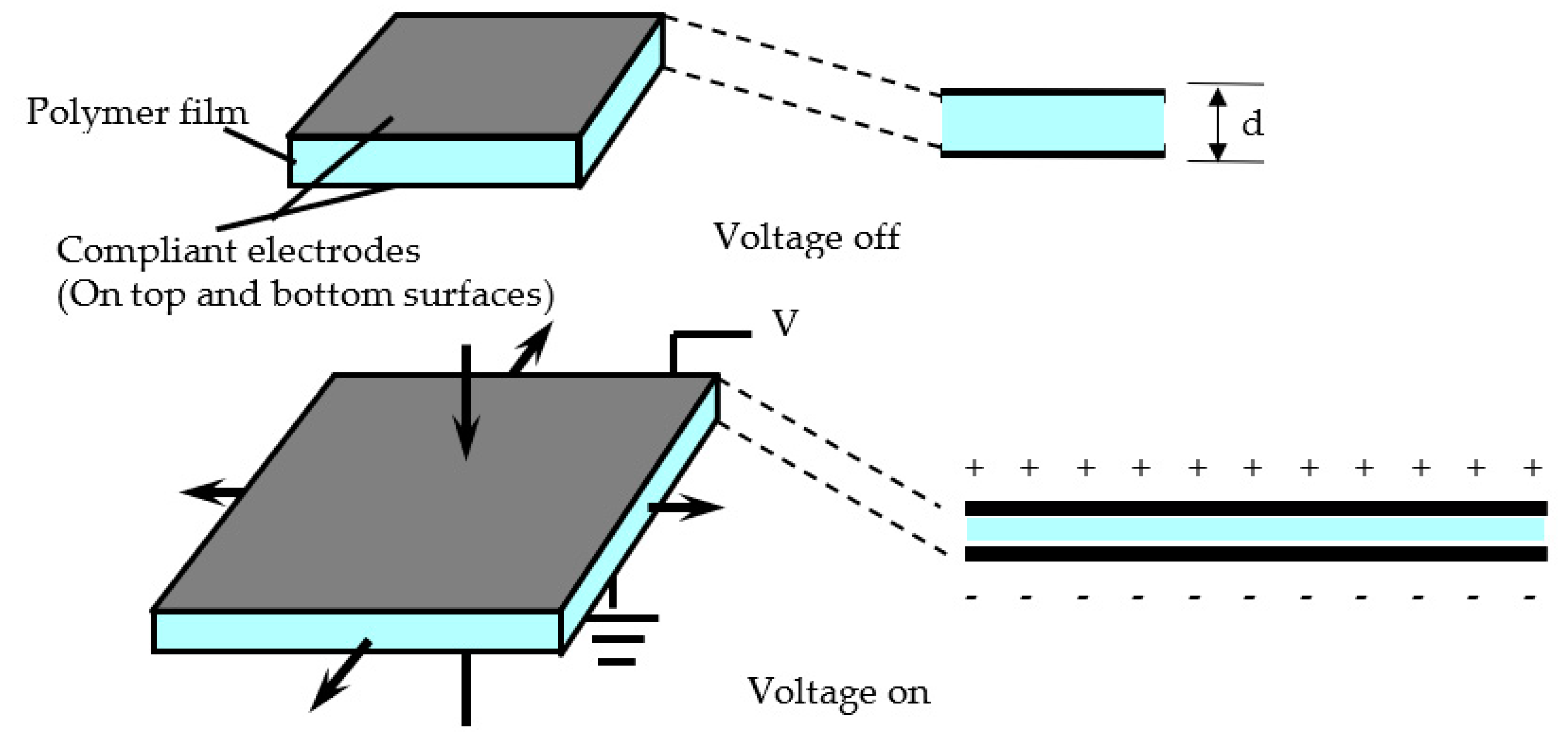
The structure of the DE is simple, consisting of an actuator sandwiched between flexible electrodes above and an elastomer (polymer) below. When a voltage is applied to the electrodes, the upper and lower electrodes are attracted by the Coulomb force and the elastomer is crushed, resulting in lateral elongation of the elastomer, forming a linear actuator that changes up to 680% [
23,
38]. The structure and principle of a DE sensor (DES) (see
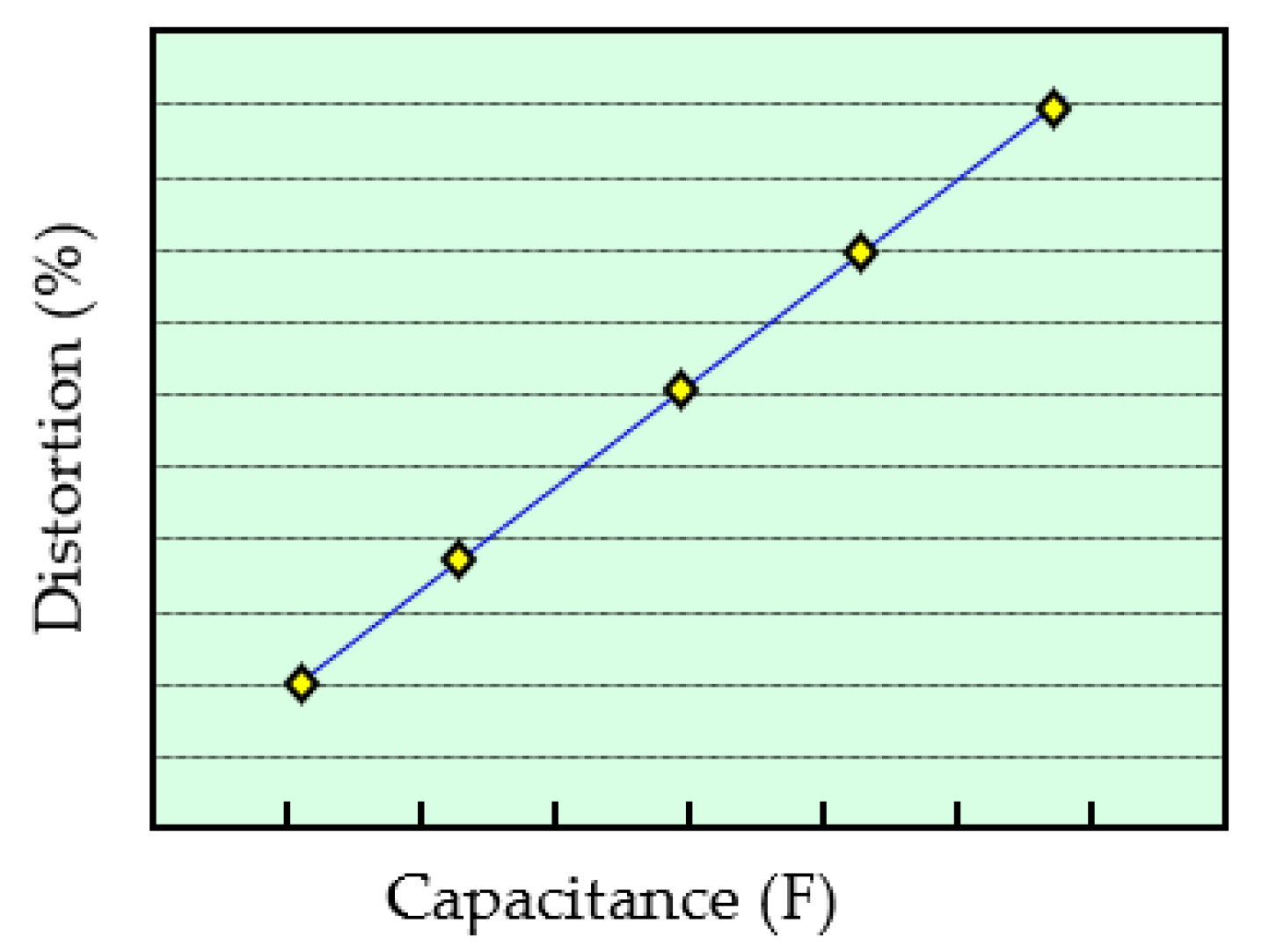
Figure 1) is the same as a DE actuator (DEA), and the drive principle is inversely proportional to DEA output and elongation. Also, the change in capacitance and its elongation in DES and DEA are directly proportional (see
Figure 2).
The relationship between DES and capacitance can be expressed by the following simple equation:
where, C is the capacitance (F), ε and ε
o are the permittivity of free space and the relative permittivity (dielectric contact) of the polymer, respectively (F/m), S is the electrode area (m
2), and d is the distance between the electrodes (m).
Also, the changed area can be obtained from the following formula.
The elongation, l is
where l is the length of the DES and w is its width. The DES is actually a cube, but its thickness is 200μ, which is small enough compared to the others in this formula to be ignored.
Electrode materials, electrode attachment methods, elastomer improvements, electrical circuits, etc. are being developed as DE/DES components. In order to produce flexible electrodes, the materials used for them include metal foil (including liquid metal), carbon grease, carbon particles (e.g., carbon black), carbon nanotubes (CNT), and conductive polymers [
4,
39,
40]. If a larger electrode deformation is required, it is better to use highly conductive CNTs (especially single-wall CNTs) [
41]. Liquid metal or carbon grease is less suitable due to grease leakage. However, with good insulation, leaks are less likely to occur, but this imposes some restrictions on operation [
4]. M. Han et al. proposed a pressure sensor composed of a CNT-polydimethylsiloxane (CNT-PDMS) composite electrode and a porous polymer dielectric layer as a medical wearable sensor [
42]. While the concept is interesting, this wearable sensor might not work well because the electrodes are not flexible enough and the polymers used are stiff. Carbon black and several different polydimethylsiloxanes (PDMS) have been studied on electrode compositions also [
43]. It used a change in resistance rather than a change in permittivity. However, using a device (a C/V converter) that can be measure even a small capacitance, a DES enables measurements of pressure at even smaller deformations [
40]. Electrodes can be made by dissolving CNT or carbon black in a solvent, mixing in a small amount of binder, and applying it to the elastomer with a brush or paint [
22,
44]. H. Shigenune et al. applied the CNT ink using a finger or a slightly larger brush, which left traces of the brush or finger on the surface of the electrode, unfortunately resulting in uneven thickness of the electrode [
44]. M. Amjadi et al., although not DE, dispersed a Multi-wall CNT (MWCNT) in a silicone elastomer and created a sensor using the change in resistance [
45]. However, after spraying, it was annealed to increase the strength of the film. As a result, the film would be stiffened and have limited elongation.
C. Walker et al. used five layers of sensors to detect the position of a robot fish fin [
46]. S. Chiba et al. prepared a softer material by adjusting the dangling chains of the elastomer and the cross-linking agent, and created a sheet-type pressure DES, demonstrating their usefulness [
39]. G. Rizzello also points out the usefulness of DESs made of thin layers of soft dielectric materials (acrylic, silicon, etc.) [
47]. Venemann et al. used a softer commercial acrylonitrile-butadiene rubber (NBR) containing a large amount of plasticizer as the base material for the dielectric layer of the DE [
48].
As an example of circuit research, K. Jung et al. used a system that mixes a low-frequency signal for operation with a high-frequency signal of small amplitude for detection to realize DEA drive and motion detection using modulation techniques. [
49]. H. Bose et al. conducted an experiment using a thicker mat-type pressure sensor instead of a sheet-type DE [
50]. They also considered making the DES structure a waveform and making it into an array. Unfortunately, however, the size of the sensor is larger than that of the sheet type, and the material is silicon, so it might not be able to expand much, which might limit its application [
51]. S. Seelecke et al. proposed side-by-side silicon-based diaphragm-type DEs to enable cooperative sensing and tactile functions [
52]. Regrettably, silicon has low elongation, and the diaphragm-type DE array type is a fixed-point measurement type sensor similar to a sensor that measures resistance. It could therefore be difficult to accurately follow the movement of limbs and measure them [
39].
Finally, as an example of a possible application, R. Walker et al. carried out a study in which DES was attached to a diver's wetsuit and movement was monitored. [
53]. C. Larson et al. placed a large number of DES on the body of a game player and attempt to apply it to a virtual reality game in which the game can be played by moving the body [
54]. As another example of system research, it was pointed out that the DEA/DES system, which combines DES and DEA, could assist in the movement of patients’ fingers, hands, feet, etc., and could possibly be used to accurately evaluate the progress of physical rehabilitation [
55]. R. Venkatraman et al. attempted to measure blood pressure using a DE cuff device [
56].
It is highly possible that the DE could be used simultaneously as an actuator and pressure and/or position sensor [
57]. In the very near future, it might also become possible to create intelligent robot limbs and nursing care equipment using DEAs/DESs, which would assist the movement of a patient's fingers, hands, feet, and so on. Furthermore, this technology could possibly evaluate the rehabilitation status with great accuracy [
58]. However, developing such devices will require further improvements in DEA/DES performance. The main factors for this are the improvement of the conductivity of the electrode and its flexibility, and the flexibility of the elastomer should also be sufficiently improved [
41,
59].
3. Experimental procedure
The purpose of this experiment is the following two points.
- (1)
A stretch DES and a pressure DES, which are made by combining SWCNT electrodes with greater stretchability and flexibility and a film with improved hardness and elongation of HNBR, are attached to robot's finger, and the motion of the finger is sensed, and the force (pressure) when the finger touches the object is detected.
- (2)
In addition, assuming the use of a virtual system or the like, in order to drive the robot's finger as the human operator wishes, stretch sensors are attached to the fingers of the human and the robot, and a system is constructed to transmit the movement of the fingers from the human to the robot. Thus, a system by replacing human finger movements with robot fingers can be demonstrated. An additional experiment was conducted in which a vibrator using a small DEA was attached to the fingertip of the robot, and the sensation of contact with the object was transmitted to the human finger.
3.1. Adjustment of elongation (hardness) and film formation of hydrogenated nitrile rubber (HNBR)
HNBR (prepared by ZEON Corporation) is a material that is laid under the car engine to absorb the vibration of the engine. HNBR can be used in relatively hot environments and has excellent heat resistance, oil resistance, dielectric strength, and a high dielectric constant. [
57]. Therefore, in the near future, HNBR is expected to be utilized in a high-power DEAs or wave power generation. However, it is now used to absorb engine vibrations, so it is stiff and not suitable for DEs. An attempt has been made to improve the elongation (hardness) by adjusting the amount of the cross-linking agent added and cutting some of the double bonds (see
Figure 1). The following shows how to adjust the amount of cross-linking added and how to cut a part of the double bond:
- 1)
How to adjust crosslinking agents:
HNBRs were dissolved in MEK (methyl ethyl ketone), organic peroxide (1,3 1,4-bis (t-butylperoxyisopropyl benzene)) was added, and it was mixed with a dispersion machine. Next, it was dried naturally to remove the solvent and obtain a mixture. Finally, the mixture was pressed at 150 ° C and made into a film.
- 2)
Dangling bond reduction method:
By reducing the double bond of the HNBR, the generation of dangling bonds caused by oxidative deterioration, or other processes, originating from the double bond was reduced. In other words, by improving the hydrogenation rate (crushing the double bond with hydrogen), both the generation of double bonds and the organic peroxide as the starting point was eliminated as much as possible, which eliminated the double bonds as much as possible.
After carefully hand-casting the HNBR film, 4 locations on the film were selected and the film thickness was checked to make sure that the film thickness was uniformly 200 μm, using a digital thickness gauge (SMD-565A-565A-565A) by TECLOCK Co., Ltd.
3.2. Tensile test
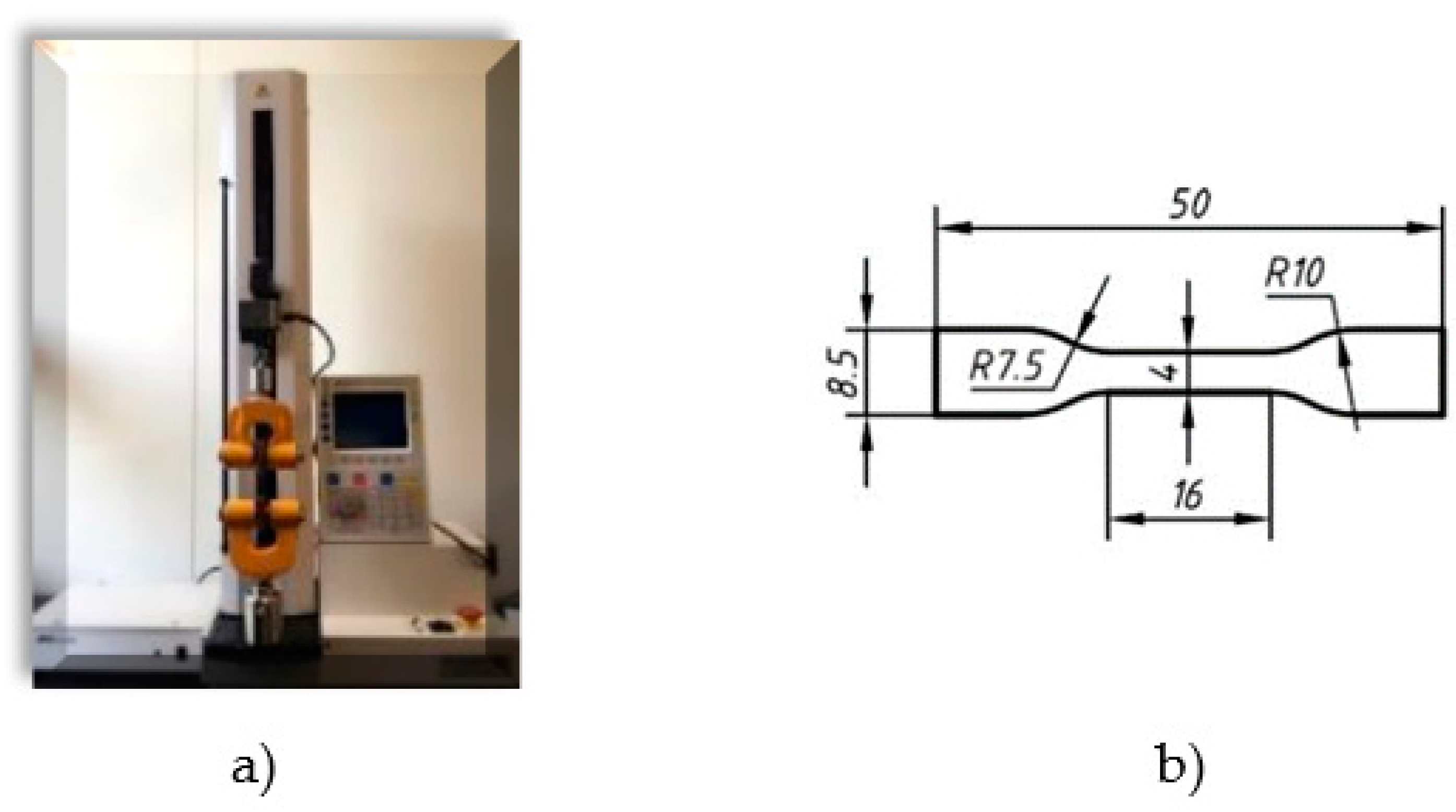
A tensile test of the dumbbell-shaped test piece (see
Figure 3b) was performed using the Orientech tabletop material tester STA-1150 (see
Figure 3a). The displacement velocity was set to 500 mm / min.
3.3. Electrode materials for DES and their adhesion method
SWCNT (Zeon corp. ZEONANO®-SG10) was selected as a highly conductive material that can be molded into a compliant electrode. A sprayable CNT solution was developed to facilitate electrode fabrication. It was prepared by mixing dispersed CNTs and a binder. For the CNT dispersion, CNT and 2 wt% sodium cholate were first added to the dispersion medium and dispersed using an ultrasonic homogenizer [
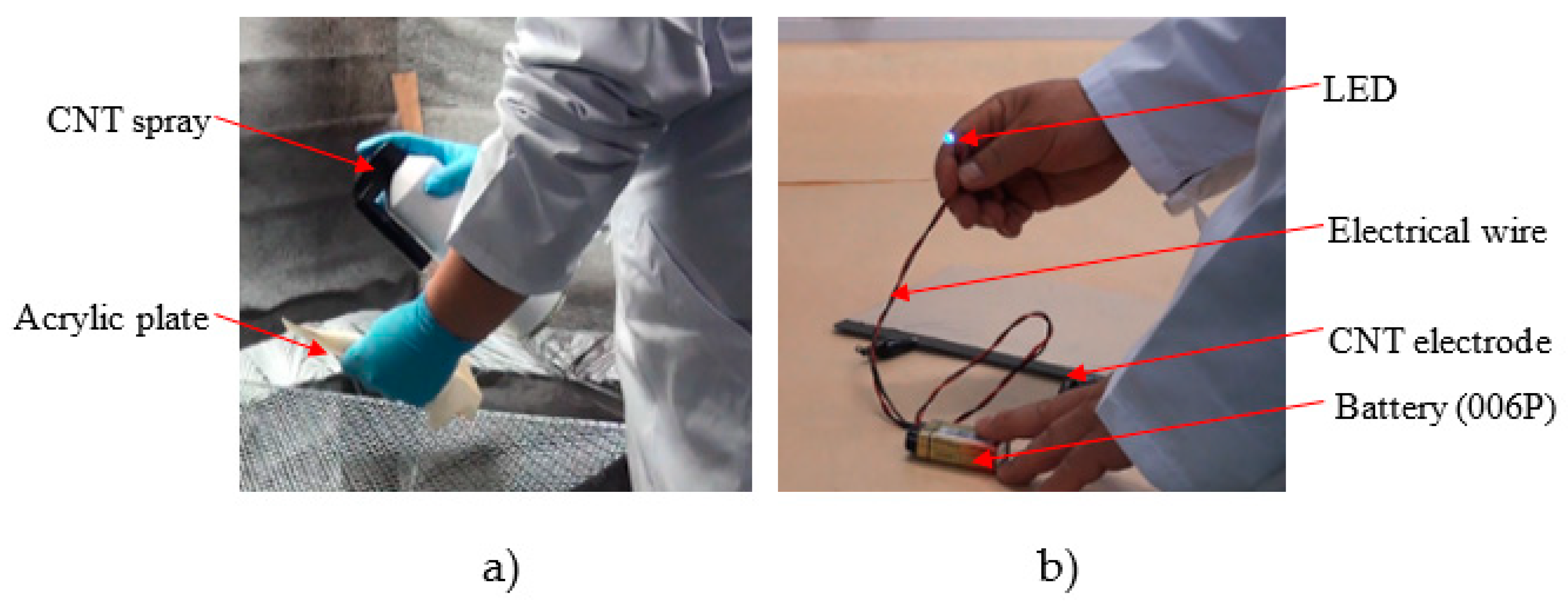
41]. This solution was placed in a spray can and used as a spray (see
Figure 4).
Figure 4a shows a scene of making a thin film electrode by spraying. The continuity test is also shown in
Figure 4b.
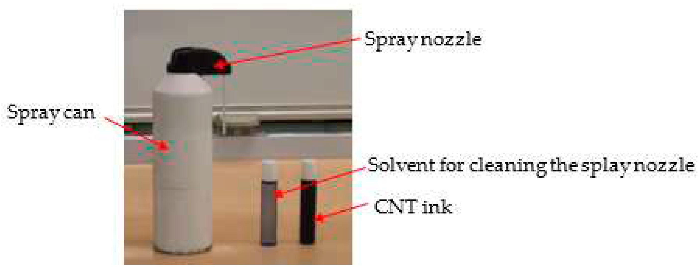
Figure 5 shows a container containing spray, dispersed CNTs and a container containing solvent. When spraying, insert a container containing CNTs is inserted into the side of the spray nozzle and used (see
Figure 4a). In addition, it is better to clean the nozzle after use, so it is recommended to insert the spray nozzle into a container with cleaning solvent and clean it. After creating the SWCNT electrode film on the elastomer, several locations were randomly selected and the thickness was measured with a Keyence double scan high-precision laser measuring instrument (LT-9500 & LT-9010M), all of which were 50 μm. In addition, in order to confirm the degree of dispersion of the SWCNTs, SWCNTs before and after dispersion were confirmed by SEM.
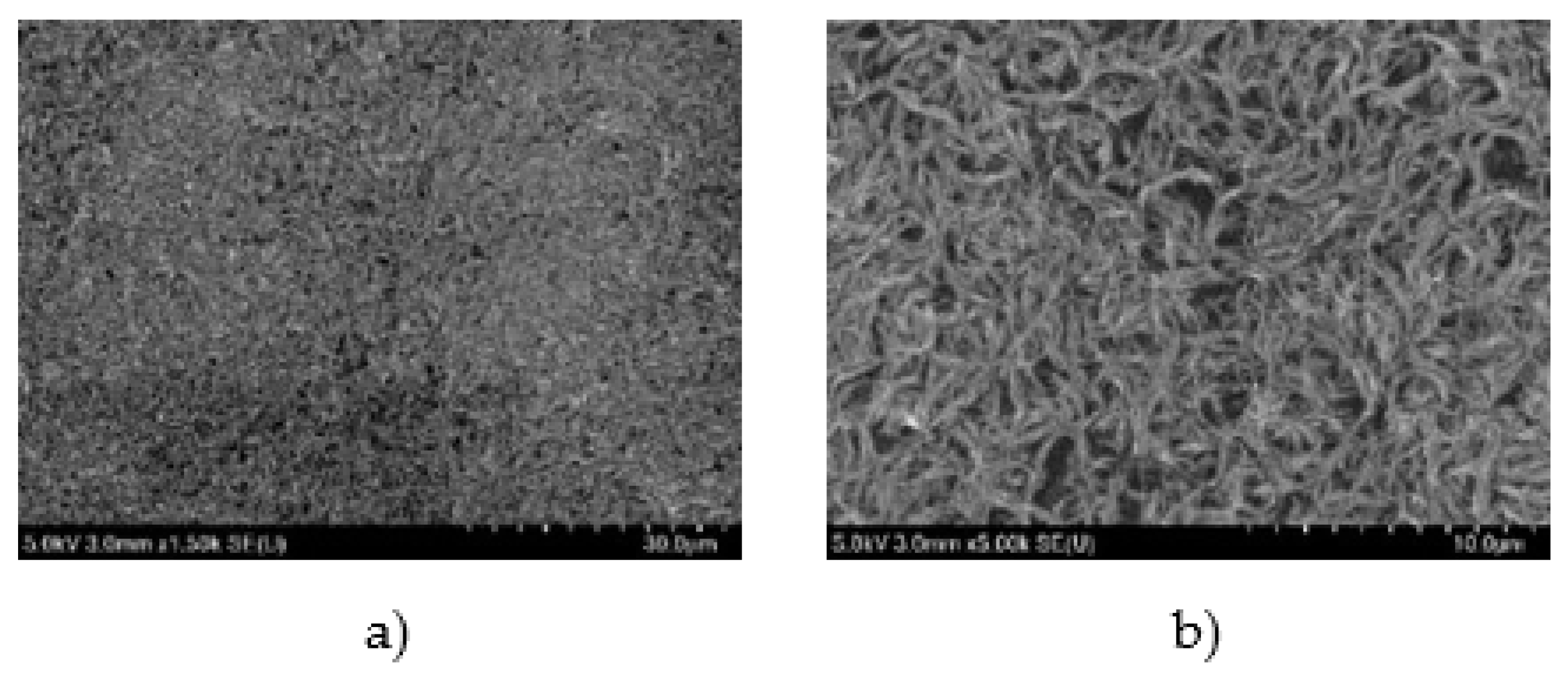
To confirm that the SWCNTs were uniformly sprayed onto the elastomer surface, four points on the surface of the DE sample were arbitrarily selected and observed using SEM.
The membrane size used was 20mm (diameter) for the pressure sensor and 10 mm x 20 mm for the stretch sensor. Both film thicknesses were 200 μm.
3.4. Measuring capability of pressure DES
The change in capacitance due to deformation of the pressure DES prepared by the above method was measured using an NF LCR METER (ZM2372).
3.4.1. Overview of the pressure DES used in this experiment
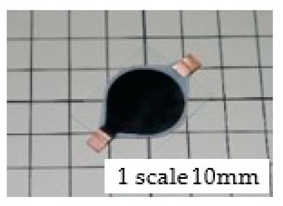
Figure 6 shows the prototype pressure DES using HNBR ver.6. This pressure DES has a diameter of 20 mm and uses the Ver.6 with a thickness of 200μm as the main material. Electrodes were created using the CNT spray introduced above. The Ver.6 is extremely soft, so, by attaching this to a sheet (supporting material) made of H05-100J manufactured by Exeal Co., Ltd., a structure can be deformed even with a small load. The H05-100J urethane material used here has a hardness of Asker C0/7, which is relatively soft.
3.4.2. Overview of the experimental system
Figure 7 is the test bench for the pressure DES. A micrometer was attached to the XYZ axis precision stage, and a load was applied from above the pressure DES to deform it and measure it. The pressure DES used in the experiment was attached to the top of the load cell installed on the XYZ axis precision stage. Two load cells with maximum measurement loads of 2 kg and 10 kg were used for measurement due to the measurement range. The analog signal output from the load cell was input to the microcomputer (ATmega328) via a dedicated AD conversion IC (HX711). After that, calibration processing was performed by the microcomputer, and the measured valkonnba-taues were displayed on the LCD. For the load measurement accuracy, it was confirmed that the error was 5% or less using a weight whose mass had been measured in advance.
3.5. Measurement of stretch ability of stretch DES
Outlines of the stretch DES used in the experiment and the experiment system are described as follows:
3.5.1. Overview of the stretch DES used in the experiment
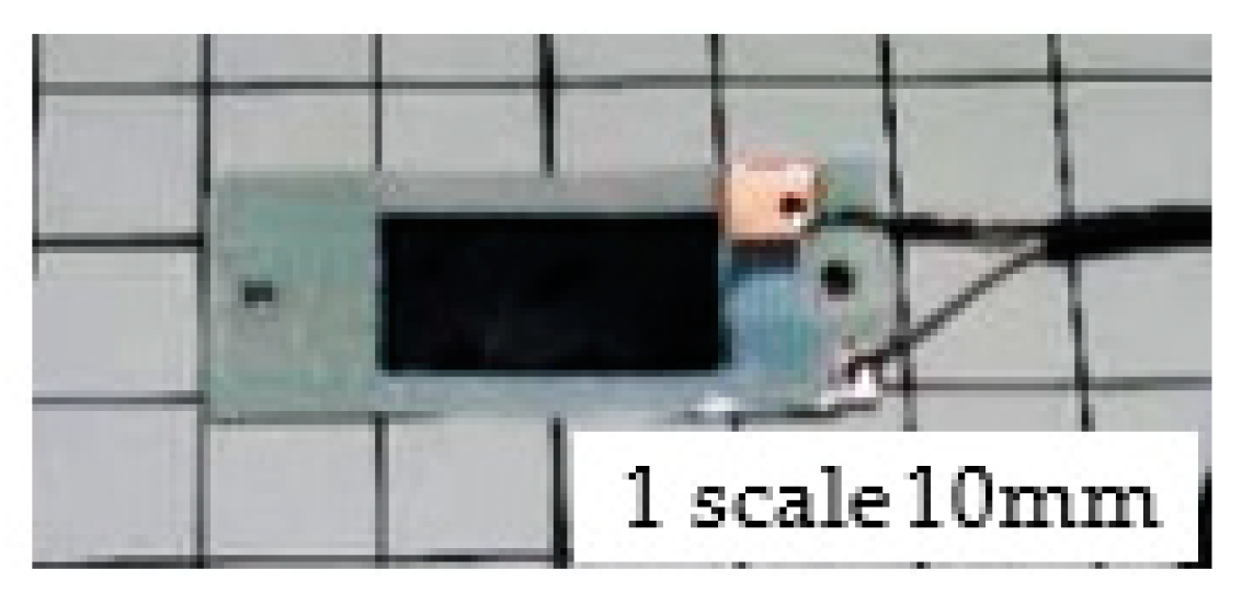
Figure 8 shows the prototype of the stretch DES using HNBR ver.6. The basic configuration is the same as the pressure DES described in
Section 3.4. However, in consideration of attaching it to a robot hand, the shape is a rectangle of 10 mm in length and 20 mm in width, and no support material is used.
3.5.2. Overview of the stretch DES system for the experiment and experimental method
The test bench for the stretch DES has a structure in which the movable part moves between the linear slides attached to the fixed part. A stretch DES can be stretched by fixing both ends to a fixed part and a movable part and rotating the ball screw. The stretched length was measured with digital calipers attached to the fixed and movable parts, and the capacitance was measured using an LCR meter (ZM2372) manufactured by NF Corporation.
Figure 9 shows the prototype of the stretch DES using HNBR ver.6.
Figure 10 shows the test bench for the stretch DES.
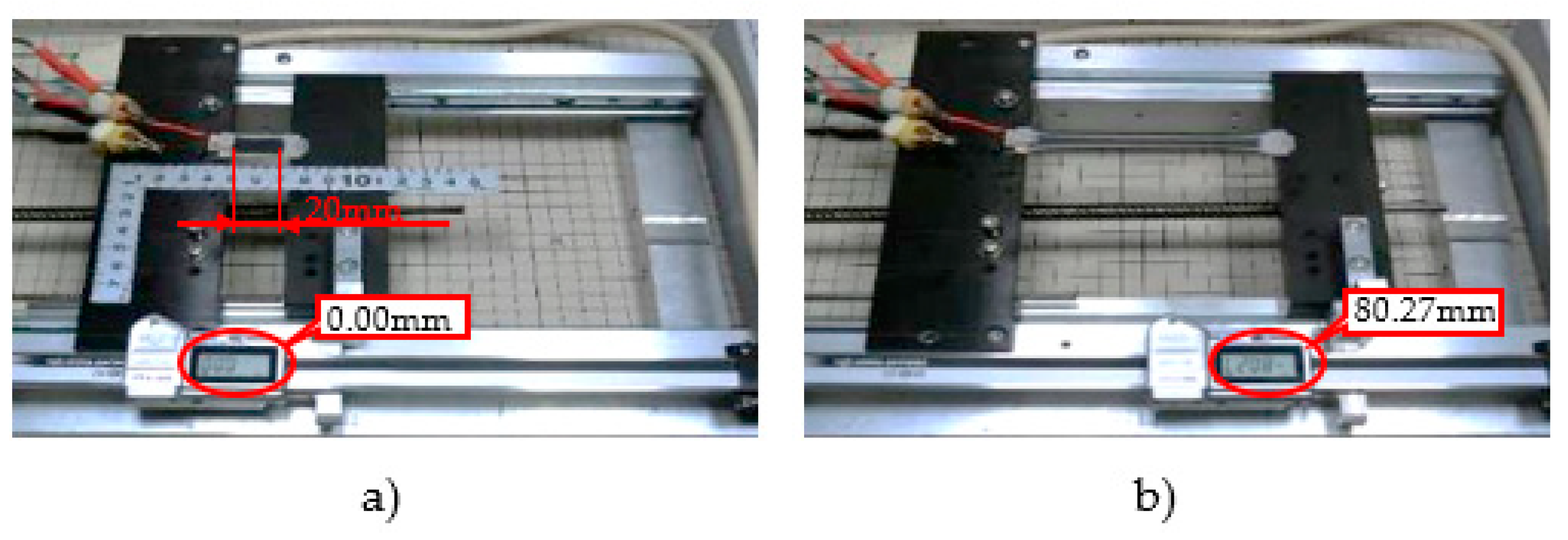
The method for measuring capacitance is shown as follows. The unstretched length of the stretch DES was set to 0 mm (see Figure 23a). From that point it was stretched to 80 mm (Figure 23b) and the capacitance was measured.
3.6. Measurement of DES response speed
The response speed of the DES pressure sensor was verified by measuring the time from when the capacitance started to change when a sudden load was applied to the DES pressure sensor until it stabilized. The DES pressure sensor used in the experiment has the same specifications as in
Section 3.4. A weight of 10g was dropped from a height of 10mm onto the DES pressure sensor mounted on the aluminum plate, and the change in the detected capacitance was converted into a voltage by the detection circuit. In the case of stretch DES, the response speed of the DES was verified by measuring the time from when the DES was stretched (or pressured) on the test bench to when the capacitance started to change. The DES sensor used in the experiment has the same specifications as in
Section 3.5. The stretch DES was stretched by a stepper motor attached to the test bench. In addition, the extension start timing was detected by a 3-axis acceleration sensor (ADXL-345 manufactured by ANALOG DEVICES Inc.) attached to the test bench.
The change in DES capacitance is converted to voltage by the detection circuit, and measured along with the decompression start timing via a 16-bit A/D conversion IC (ADS1115) made by TEXAS INSTRUMENTS and a microcomputer (ATmega328P) made by Atmel.
Figure 10 shows how the DES response speed is measured.
Figure 10.
Measuring the response speed of a DES.
Figure 10.
Measuring the response speed of a DES.
As with the stretch sensor, changes in DES capacitance were converted to voltage by a detection circuit and measured via a 16-bit A/D conversion IC (ADS1115) made by Texas Instruments and a microcomputer (ATmega328P) made by Atmel.
3.7. Measurement of robot finger movement and finger pressure, and an experiment to transmit the sensation of the robot finger touching an object to a human finger
First, the motion of the robot's finger was sensed using a stretch DES, and the force (pressure) when the fingertip touched the object was measured.
Figure 11 shows the stretch DESs and pressure DESs attached to the robot hand.
Five pressure sensors were used and attached to the tip of each finger. The shape of the pressure sensor was a circle with a diameter of 20 mm. The stretch sensor was a rectangle of 20 mm in length and 10 mm in width. Five stretch sensors were attached to the base of each finger. The detection circuit of each sensor was placed on the back of the hand to shorten the analog signal wiring and prevent malfunction. Five model micro servo motors (product model number: MG90S) with a maximum torque of 2.2 kg/cm and a weight of 13 g were used to drive the fingers.
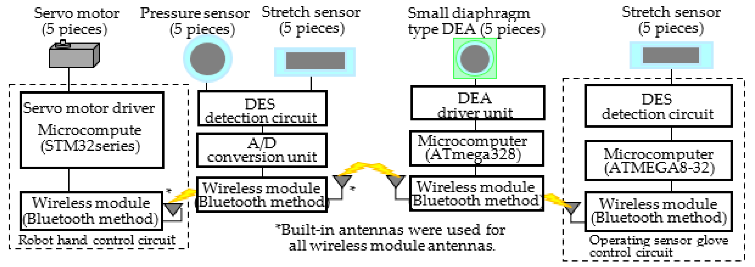
Figure 12 shows a block diagram of the drive system and sensing circuit of the robot hand.
A microcomputer (STM32 series) manufactured by STMicroelectronics was used to drive the robot hand. Also, by connecting the microcomputer and the local control PC with a USB cable, it can be moved like a human hand. A pressure sensor and a stretch sensor are attached to each finger. The signals detected by these sensors were converted to analog signals by the detection unit, converted to digital signals by the A/D conversion unit, and then recorded by the measurement PC. The A/D conversion unit used for the measurement consists of a 16-bit A/D conversion IC (ADS1115) manufactured by TEXAS INSTRUMENTS and a microcomputer (ATmega328P) manufactured by Atmel (see
Figure 13).
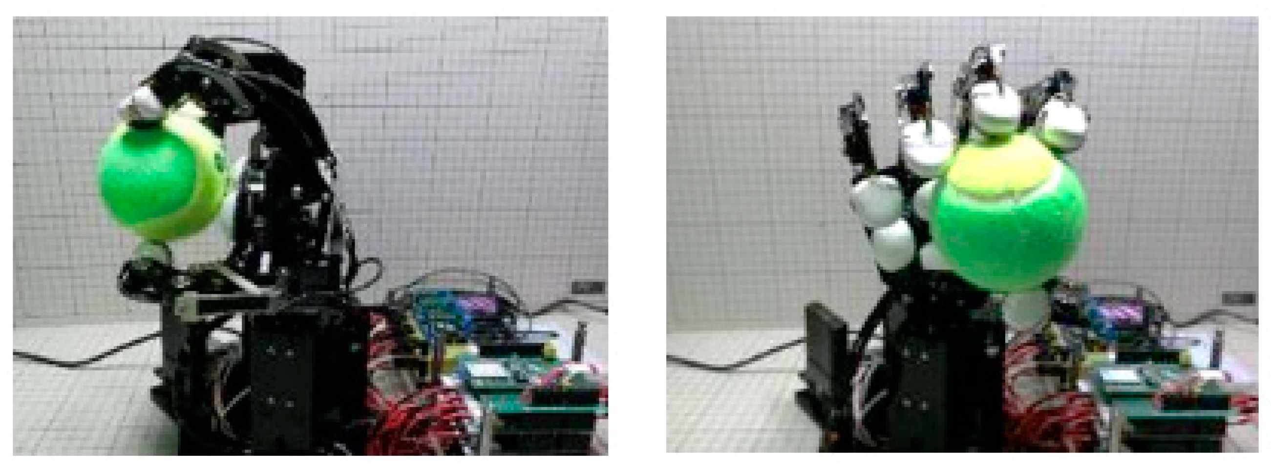
Figure 13 shows a driving experiment of a robot hand equipped with the pressure sensor and the stretch sensor. Using this system, the detection status of the pressure sensor and stretch sensor was confirmed by holding the ball with the thumb and index finger.
By bending the index finger of the robot hand, it was confirmed that the detection signal of the stretch sensor increases. Also, it was confirmed that the pressure sensor responds when the tip of the index finger touches the ball. In addition, an experiment was also conducted to transfer human finger movements to robot fingers. Furthermore, an experiment was conducted in which a small diaphragm-type vibration DEA (active part diameter: 6 mm) [
60] was applied to a human finger to feed back the sensation of the robot finger touching an object to the human finger.
Figure 14 shows how a small diaphragm-type vibration DEA is attached to a human hand.
Figure 14a is a small diaphragm-type vibrating DEA. The donut-shaped black parts are the electrodes, which are placed in front and back with the elastomer sandwiched between them.
Figure 14b shows a small diaphragm-type vibration DEA unit mounted in a control sensor glove. The brown part is insulating tape made of polyimide. Fingers and the DEA are held in the glove by acrylic DEA folders.
The DEA had an outer diameter of 6 mm, and the elastomer used was 3M4905. Electrodes were made by spraying SWCNTs (see
Figure 6) [
60]. As mentioned above in how to make a pressure DES, the reason why HNBR ver.6 was not used for this vibrator DE is that the Ver.6 is too soft for the DE.
Next,
Figure 15 shows a block diagram of the driving system and sensing circuit of the robot hand, the sensor glove, and the small diaphragm DEA driving system.
The drive system and sensing circuit of the robot hand are almost the same as those shown in
Figure 13 above, but the following points have been changed in order to connect the operating sensor glove and the small diaphragm DEA drive system.
The first change is that in
Figure 12, the servo motor drive signal was supplied from the local control PC, but in this system, the servo motor drive signal is supplied from the operation sensor glove via the wireless module. This makes it possible to remotely control the robot hand from several meters away. The second change is that the signal detected by the pressure sensor is used as the drive signal for the small diaphragm DEA. In this system, the analog signal detected by the pressure sensor is converted into a digital signal by the microcomputer (ATmega328) installed in the A/D converter unit, and supplied to the drive system of the small diaphragm DEA via the wireless module. Next, an overview of the operation of the operation sensor glove and the drive system of the small diaphragm DEA will be described. A finger movement is detected as a change in capacitance by a stretch sensor attached to the operation sensor glove. The detected change in capacitance is converted to an analog signal by the DES detection circuit and supplied to an Atmel microcomputer (ATmega8-32). The drive signal for the small diaphragm DEA is generated by a microcomputer (ATmega328) based on the pressure signal supplied from the robot hand, adjusted to an appropriate voltage by the DEA driver, and then supplied to the small diaphragm DEA.
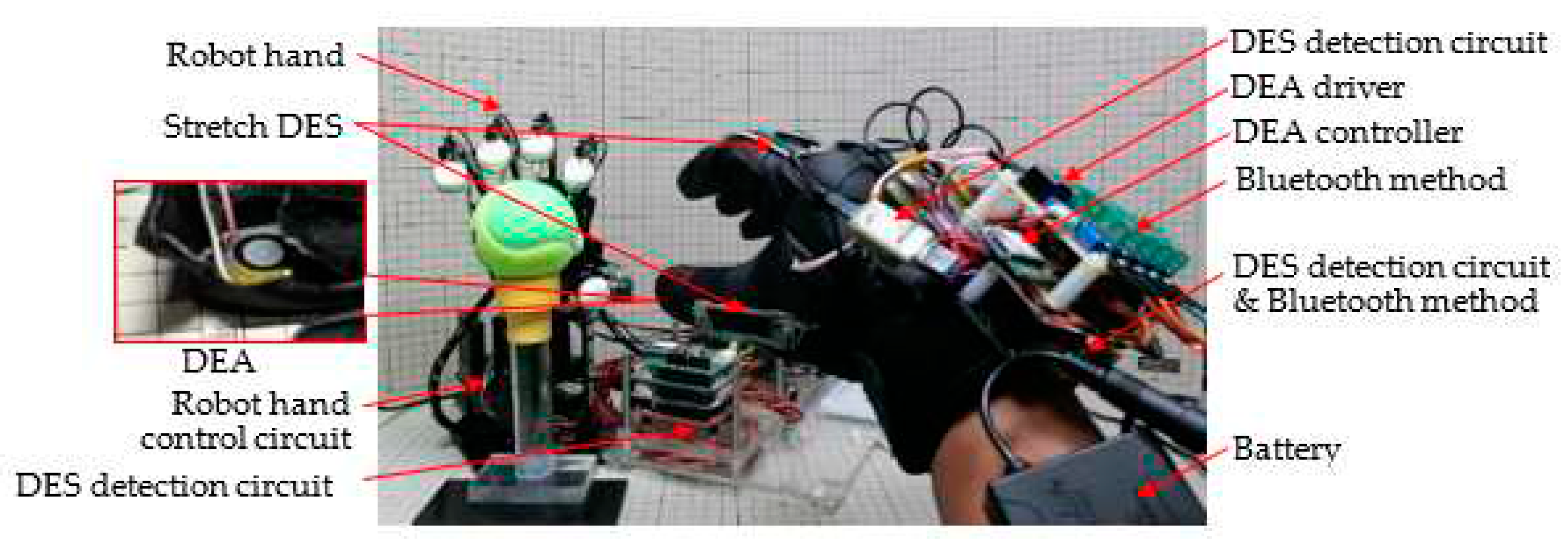
Figure 16 shows how the prototype robot hand is controlled by the operation sensor glove.
5. Discussion
As mentioned above, the pressures that can be measured up to now range from about 5kgf to about 120kgf, and pressures lower than about 5kgf could not be measured [
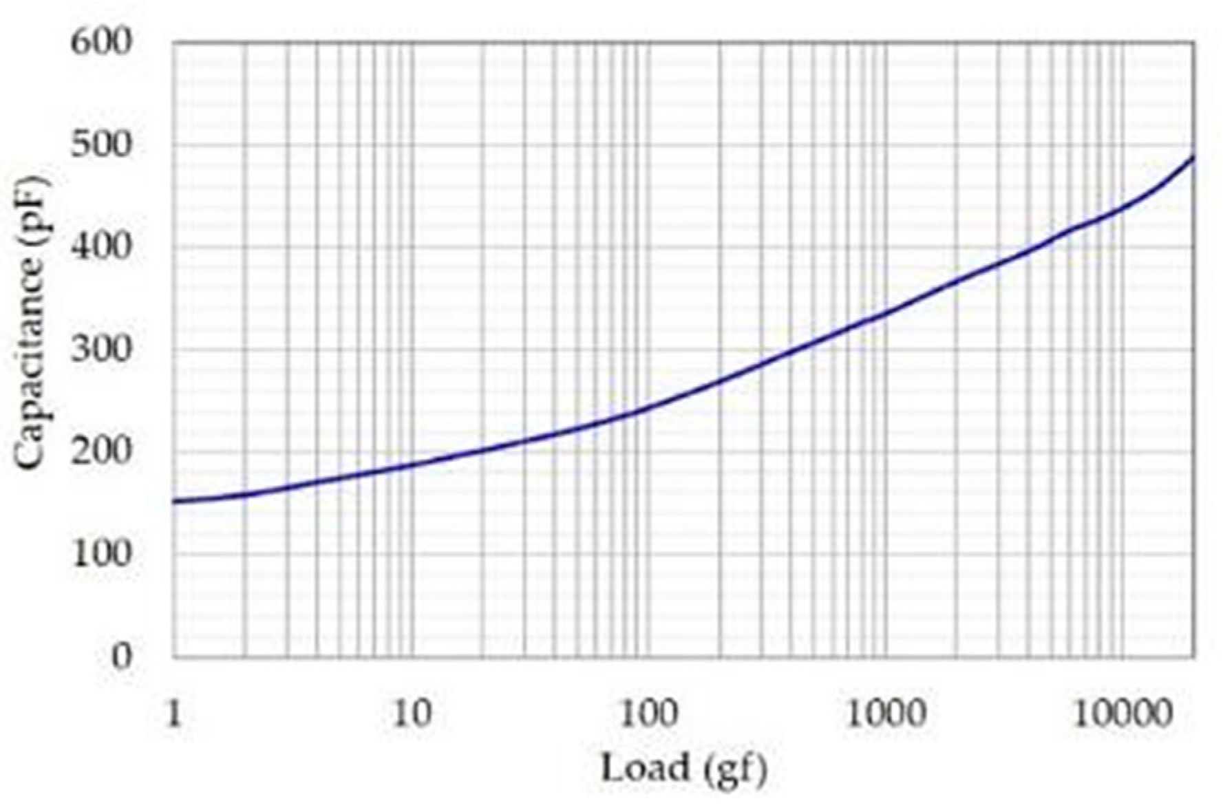
39]. However, this time it became possible to measure from 1gf to 20kgf (see
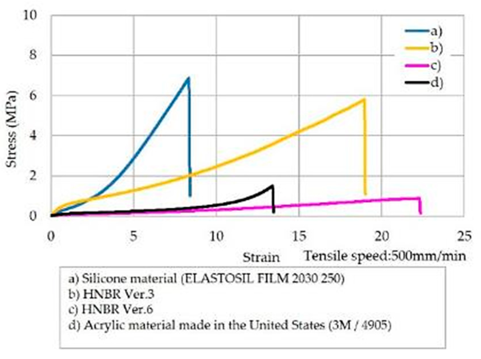
Figure 20). A major factor behind this is that the yield point stress values of 3M acrylic film (4905) and HNBR ver.6 are about half or less (see
Figure 26). In other words, even if a little pressure is applied, the film can be deformed, and the slight change in capacitance can be measured.
This HNBR pressure DES can measure any pressure anywhere within the measuring range. As mentioned above, the reason for this is that Ver.6 has been softened, and another point is that it depends on the circuit design (see Chapter 3.4). Circuits with higher amplification can also be used to measure smaller changes, thus increasing the measurement range. In other words, the pressure measurement range of the DES changes depending on the hardness of the material used, the shape of the sensor, the tune-up of the detection circuit, etc., so it is important to select those specifications according to the purpose [
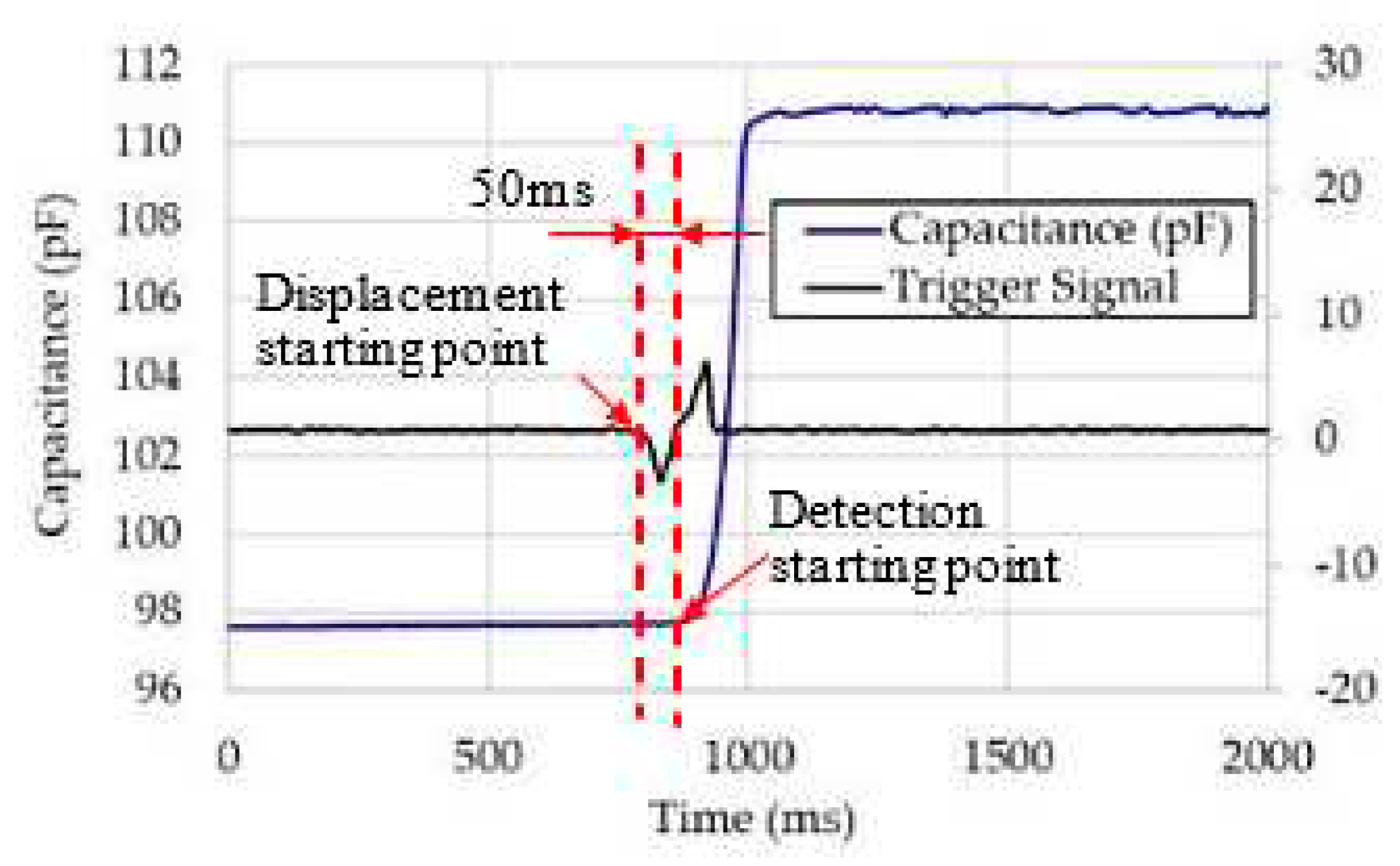
39]. From those results, it is possible to improve their performance. Incidentally, in this experiment, the response speed of this DES was 50ms. This response speed, like pressure measurement, also depends on the hardness of the film and the circuit.
Table 2 shows the response speed of the pressure sensor for different elastomer types and electrode types [
39]. As shown in
Figure 26, it can be seen that the silicon material is harder than other films, and as seen in
Table 2, it has a fast response speed as a sensor. However, due to its small elongation, its application is considered to be limited. In other words, materials with low dynamic viscoelasticity, such as silicon, are not suitable DEA/sensor materials [
39]. On the other hand, acrylic and HNBR are softer and more elastic than other films, making them suitable materials for sensors. The response speed is also sufficient for practical use, and it seems to be optimal as a sensor that is used in close contact with a person's finger.
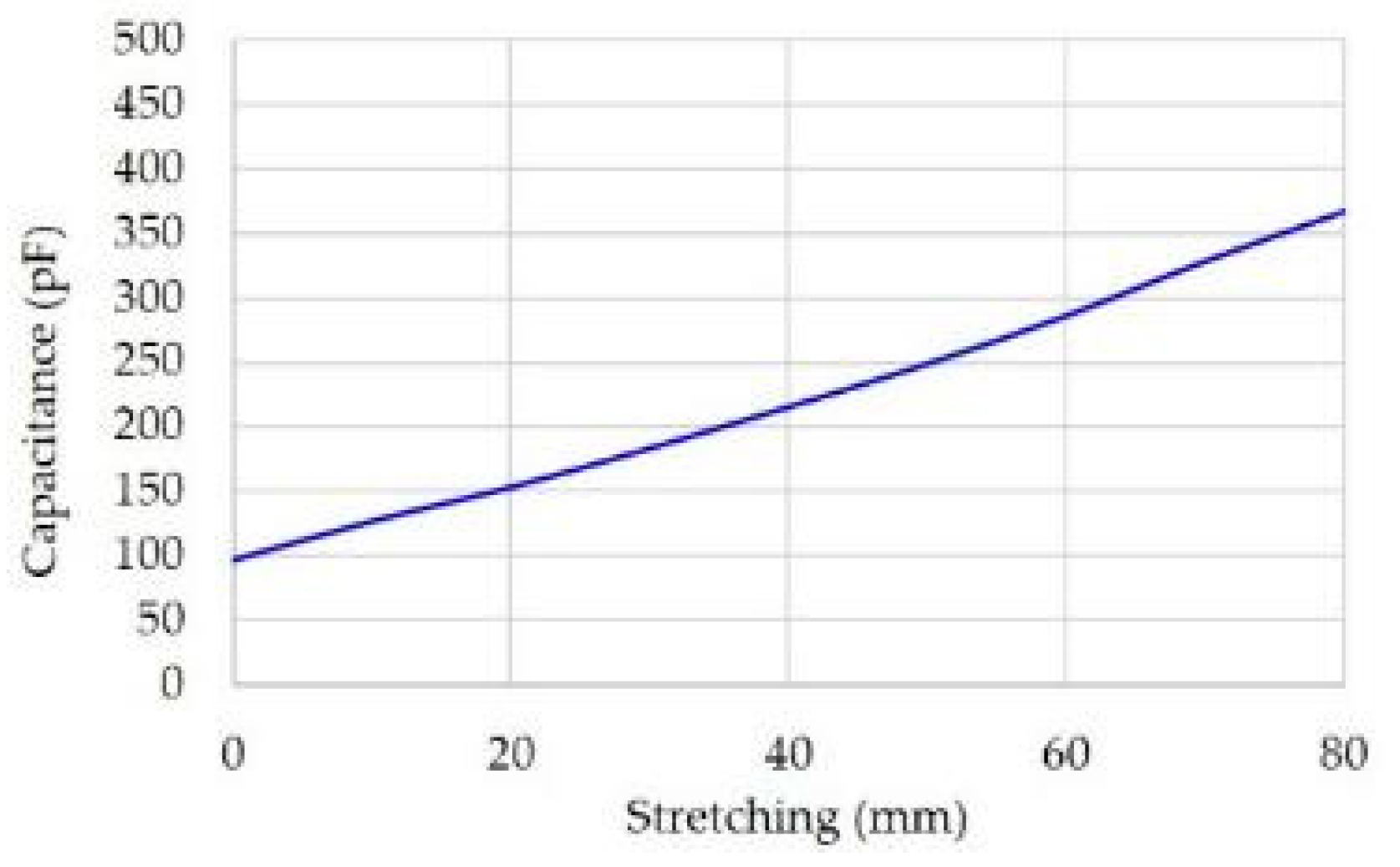
It was found that the capacitance of this stretch sensor changes even when it is stretched by only about 10%, and the capacitance changes almost linearly even after it was even stretched by more than 400% (see
Figure 22). Also, the speed of stretch DES was 50ms. In this experiment, the stretch DES was attached to a human glove in close contact. As a result, the sensor responded to the bending motion of the glove (fingers), and the motion could be transmitted to the robot quickly in a synchronized state. In other words, it seems that this sensor speed was fully sufficient. A stretch DES, like a pressure DES, also depends on the stiffness of the membrane. In the case of the circuit, as mentioned again, using a higher amplification circuit allows smaller changes to be measured, increasing the measurement range. Thus, the elongation of this sensor depends on hardness, as it does with pressure.
It was also confirmed that the feeling of the robot fingertip touching the ball was obtained from the small diaphragm DEA attached to the operation sensor glove for a human operator (see
Figure 25). In this prototype system, four microcomputers and four wireless modules are used to construct the system, but by reviewing the circuit, it is thought that the number of these used can be reduced to about half. Also, since the wireless module used this time uses the Bluetooth method, the operation range was several meters, but by changing the wireless module to the Wi-Fi method, the operation range can be extended to several tens of meters. From these matters, it has become possible to move the robot's finger in real time in accordance with the movement of a human.
Furthermore, if the Internet is available, it can be operated from anywhere in the world. The use of 5G and 6G technology, which has been expanding in its use, will enable low-latency operation, so it can be applied to fields such as telemedicine that require precise operation. HNBR Ver.6 at this time is not suitable for DEAs because the adjustment method of the amount of cross-linking agent and the adjustment of dangling bonds were altered considerably, so the hardness was considerably reduced, so the strength of the film was low. Therefore, 3M/4905 was used in this experiment.
Moreover, if this stretch sensor has the capability to be used as a three-dimensional position sensor for the arms and legs of robots and the like. To explain step by step, first a stretch sensor would be attached to the upper side of the arm of the robot. When the arm is moved upward, the upper sensor is contracted, and the lower sensor is extended, so that it is possible to two-dimensionally determine at what angle the arm is bent. Furthermore, if another pair of sensors are arranged on the side of the arm, sensing diagonal movement is also possible. That is, the three-dimensional position can be easily determined from the difference in dielectric constant between the top and bottom and the difference in dielectric constant between the sides. Therefore, it is beneficial to prepare such a calculation table in the microchip.
It is expected that robots will work together with humans in the very near future, and it is necessary to match the movements of humans, so humanoid robots are desired. However, as the frequency of contact with humans increases, there is a strong need for robots to be safe for humans. For example, when a robot's hand touches a person, an excellent sensor can instantly determine that it is a person and stop the robot's movement or sufficiently reduce its output.
With this human-robotic interaction system shown above, a physician can possibly use a virtual system to palpate a patient when the patient is at a remote location [
61]. In addition, in the assembly of a machine, when performing a detailed and sensitive assembly, it might be possible for a robot to do such work alone someday, although it still requires a skilled human at present. Using this system and AI, a robot could be taught the movements for its hands and fingers. As another example, it will become possible to feel the sensations shaking a hand or hugging someone virtually. As a step to realize the above-mentioned goals, the points obtained in this experiment might be a guideline for making an AI robot that could move and make decisions like humans in the future.
In 2012, the authors developed a system for the rehabilitation of patients who could not move their fingers due to conditions such as cerebral infarction by setting a DES capable of measuring the stretch of the patients’ fingers and measuring how much they can move their fingers [
62]. However, the DES at that time was not able to obtain sufficient elongation, which made it difficult to measure. However, with the new system, sufficient elongation can be obtained, so it is thought that the measurement can be performed accurately. Also, during rehabilitation, it is necessary to move the patient's fingers with the external force, but the DEA so far has not been able to respond sufficiently due to the small output. If the above DEA system (mentioned in Background of Dielectric Elastomers) developed in 2021 could be used, it would be possible to realize such a rehabilitation system without any problems [
23].
As an electrode material, compared to multi-walled CNTs (MWCNTs) and carbon black, SWCNTs are more conductive, allowing for thinner electrodes and greater stretchability [
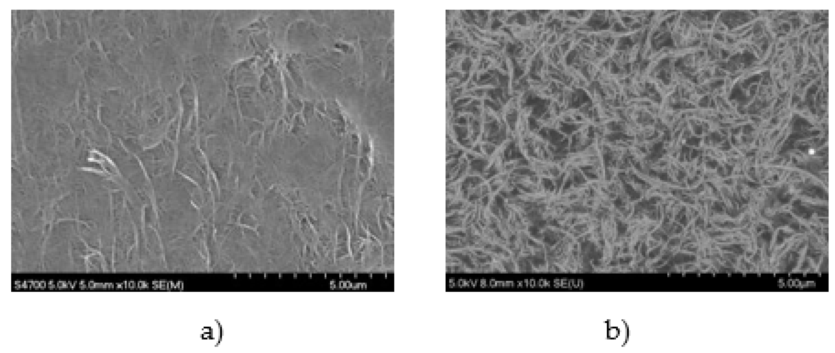
41]. In this experiment, the SWCNTs were sufficiently dispersed (see
Figure 18), so even if the SWCNTs were packed in the spray, they could be sprayed without clogging [
64].
It is worth mentioning that the above spray can impart conductivity to various materials such as wooden boards, glass, epoxy, rubber bands, elastomers, and insulating sheets. As a result, it is also easy for electrodes to follow curved surfaces (see
Figure 27). It also remains conductive when bent, stretched, and rubbed. In addition, it will not come off even if when bent, stretched, or rubbed. Moreover, in terms of temperature resistance, HNBR sensors with SWCNT electrodes may be used at temperatures above 200 °C [
63].
Figure 1.
Structure and principle of DES.
Figure 1.
Structure and principle of DES.
Figure 2.
Relationship between the elongation of the DES and capacitance.
Figure 2.
Relationship between the elongation of the DES and capacitance.
Figure 3.
Desktop material tester (Orientech STA-1150) shown in a) and the dumbbell-shaped test piece shown in b).
Figure 3.
Desktop material tester (Orientech STA-1150) shown in a) and the dumbbell-shaped test piece shown in b).
Figure 4.
Using SWCNT spray to generate electrodes on the object (Fig. 4a) and the continuity test (Fig. 4b): a) SWCNTs being sprayed on objects; b) After spraying, test operation with LED and battery.
Figure 4.
Using SWCNT spray to generate electrodes on the object (Fig. 4a) and the continuity test (Fig. 4b): a) SWCNTs being sprayed on objects; b) After spraying, test operation with LED and battery.
Figure 5.
A SWCNT spray set.
Figure 5.
A SWCNT spray set.
Figure 6.
The prototype of a pressure DES using HNBR.
Figure 6.
The prototype of a pressure DES using HNBR.
Figure 7.
Overview of the test bench used for the pressure DES experiment.
Figure 7.
Overview of the test bench used for the pressure DES experiment.
Figure 8.
The prototype stretch DES.
Figure 8.
The prototype stretch DES.
Figure 9.
The test bench for the stretch DES.
Figure 9.
The test bench for the stretch DES.
Figure 11.
The stretch DESs and pressure DESs attached to the robot hand.
Figure 11.
The stretch DESs and pressure DESs attached to the robot hand.
Figure 12.
Block diagram of the drive system and sensing circuit of the robot hand.
Figure 12.
Block diagram of the drive system and sensing circuit of the robot hand.
Figure 13.
State of driving experiment of robot hand.
Figure 13.
State of driving experiment of robot hand.
Figure 14.
Attaching a small diaphragm-type vibration DEA to the fingertip: a) a small diaphragm-type vibration DEA; b) the DEA attached to a human finger.
Figure 14.
Attaching a small diaphragm-type vibration DEA to the fingertip: a) a small diaphragm-type vibration DEA; b) the DEA attached to a human finger.
Figure 15.
Block diagram of the drive system and sensing circuit of the robot hand, the operating sensor glove, and the small diaphragm type DEA drive system.
Figure 15.
Block diagram of the drive system and sensing circuit of the robot hand, the operating sensor glove, and the small diaphragm type DEA drive system.
Figure 16.
Prototype robot hand and operation sensor glove.
Figure 16.
Prototype robot hand and operation sensor glove.
Figure 17.
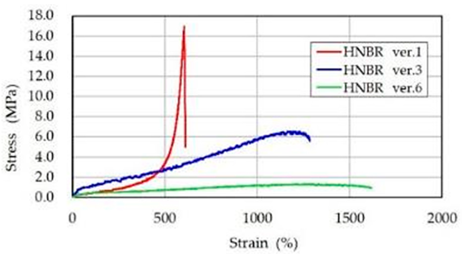
HNBR tensile test results.
Figure 17.
HNBR tensile test results.
Figure 18.
SWCNTs before and after dispersion (magnification: X10,000): a) SWCNT before dispersion; b) SWCNTs after dispersion.
Figure 18.
SWCNTs before and after dispersion (magnification: X10,000): a) SWCNT before dispersion; b) SWCNTs after dispersion.
Figure 19.
Electrode surface by spraying SWCNTs: a) Magnification: X1,500; b) Magnification: X5,000).
Figure 19.
Electrode surface by spraying SWCNTs: a) Magnification: X1,500; b) Magnification: X5,000).
Figure 20.
The capacitance when a load of 1gf to 20kgf is applied.
Figure 20.
The capacitance when a load of 1gf to 20kgf is applied.
Figure 21.
Changes in measured capacitance.
Figure 21.
Changes in measured capacitance.
Figure 22.
A graph showing changes in capacitance when the stretch DES is stretched.
Figure 22.
A graph showing changes in capacitance when the stretch DES is stretched.
Figure 23.
Photographs of the stretch DES stretched over 400%: a) before stretching; b) after stretching.
Figure 23.
Photographs of the stretch DES stretched over 400%: a) before stretching; b) after stretching.
Figure 24.
The fingertip pressure and finger displacement detected by the pressure sensor and stretch sensor attached to the index finger of the robot hand: a) Movement to hold the ball with the thumb and index finger); b) Transitions of the analog signals of fingertip pressure and finger displacement detected by the pressure sensor and the stretch sensor.
Figure 25.
Manipulation of the robotic hand using the manipulator sensor glove: a) grasping using all fingers, b) opening index and middle fingers and c) opening all fingers.
Figure 25.
Manipulation of the robotic hand using the manipulator sensor glove: a) grasping using all fingers, b) opening index and middle fingers and c) opening all fingers.
Figure 26.
The results of the SS curves of the silicon (ELASTOSIL FILM 2030 250: shown in blue), the acrylic material made in the United States (3M / 4905: shown in black), and the HNBR (ver.3: shown in orange and ver.6: shown in pink).
Figure 26.
The results of the SS curves of the silicon (ELASTOSIL FILM 2030 250: shown in blue), the acrylic material made in the United States (3M / 4905: shown in black), and the HNBR (ver.3: shown in orange and ver.6: shown in pink).
Figure 27.
Image of forming electrodes by spraying SWCNT on various materials.
Figure 27.
Image of forming electrodes by spraying SWCNT on various materials.
Table 1.
Adjusting HNBR additives and reducing dangling bonds.
Table 1.
Adjusting HNBR additives and reducing dangling bonds.
| |
Crosslinking agent
(when rubber is 100) |
Crosslinking agent name |
Crosslinker
(molecular weight) |
Double bond amount (%) |
| HNBR original film |
8 |
1,3 1,4-bis (t-butyl alcohol isopropyl alcohol) Benzene |
338.5 |
10 |
| HNBR film ver.1 |
8 |
Same as above |
338.5 |
5 |
| HNBR film ver.3 |
2 |
Same as above |
338.5 |
1 |
| HNBR film ver.6 |
1 |
Same as above |
338.5 |
1 |
Table 2.
Difference in response speed when changing the type of elastomer and electrode.
Table 2.
Difference in response speed when changing the type of elastomer and electrode.
| |
Carbon grease |
Carbon black |
SWCNT |
Silicone material
(ELASTOSIL FILM 2030 250) |
69 |
66 |
59 |
| HNBR Ver.3 |
80 |
78 |
68 |
| Acrylic material made in the United States (3M / 4905) |
93 |
86 |
73 |
| The film that corrected the distortion of the 3M/4905 acrylic |
94 |
88 |
74 |

