1. Introduction
To accommodate the diverse quality-of-service (QoS) requirements of a wide range of applications in various scenarios, future communication networks are envisioned to offer low latency and ubiquitous connectivity [
1]. In particular, the space-air-ground integrated network (SAGIN) is considered a promising paradigm for future communication to provide large-scale coverage and network performance enhancement [
2].
On the other hand, mobile edge computing (MEC) is considered one of the key technologies for future communication network severice for latency-sensitive tasks [
3,
4]. Meanwhile, the execution of tasks would consume a considerable amount of energy. Green communication in 6G should be manifested in reducing the total energy consumption in order to achieve energy efficiency goal [
5]. In addition, The dual carbon goal of future communication networks is to reduce carbon emissions by 50% [
6]. Thereby, joint latency-oriented for QoS guarantee, energy consumption for green communication and carbon reduction for dual carbon goal in SAGIN has attracted wide attention from both academia and industry.
Several studies have been put into reducing network latency for QoS guarantee. Peng et al. [
7] consider two typical MEC architectures in a vehicular network and formulate multi-dimensional resource optimization problems, exploiting reinforcement learning (RL) to obtain the appropriate resource allocation decisions to achieve high delay/QoS satisfaction ratios. Through jointly optimizing computation offloading decision and computation resource allocation, Zhao et al. [
8] effectively improve the system utility and computation time. Abderrahim et al. [
9] propose an offloading scheme that improves network availability, while reducing the transmission delay of ultra-reliable low-latency communication packets in the terrestrial backhaul and satisfying different QoS requirements.
Furthermore, a few other studies have considered the issue of energy consumption in networks. Literature [
10,
11] consider a multi-user MEC system with the goal of minimizing the total system energy consumption over a finite time horizon. Chen et al. [
12] investigate the task offloading problem in ultra-dense network and formulate it as a mixed integer nonlinear program which is NP-hard, which can reduce 20% of the task duration with 30% energy saving, compared with random and uniform task offloading schemes.
Some scholars have concentrated their attention on latency and energy consumption for the SAGIN network architecture. Guo et al. [
13] investigate service coordination to guarantee the QoS in SAGIN service computing and propose an orchestration approach to achieve low cost reduction in service delay. To achieve a better latency/QoS for different 5G slices with heterogeneous requirements, Zhang et al. [
14] offload smartly the traffic to the appropriate segment of SAGIN. In order to ensure QoS for airborne users as well as to reduce energy consumption, Chen et al. [
15] design an energy-efficient data saving scheme with extensive simulations confirming the effectiveness of the proposed scheme in terms of both the energy consumption and the processing delay in SAGIN.
Although the aforementioned studies have done a considerable amount of exploration on the issues of latency reduction and energy consumption reduction, research in [
16] highlights that the dense deployment of higher energy-demanding communication devices will keep pumping up the energy consumption of wireless access networks. Moreover, the future networks have to reduce carbon emission. Fortunately, energy harvesting technology converts ambient energy to electric energy, which can be used in cellular networks to help reduce the carbon footprint of wireless networks [
17]. In particular, the approach to green cellular BS has been proposed, which involves the adoption of renewable energy (RE) resources [
18].
Consequently, the subject of utilizing RE to power BS reduce the carbon footprint of the network attracted academic attention. Yuan et al. [
19] propose an energy storage assisted RE supply solution to power the BS, in which a deep reinforcement learning (DRL) based regulating policy is utilized to flexibly regulate the battery’s discharging/charging. On the basis of off-grid cellular BSs powered by integrated RE, JAHID et al. [
20] formulate a hybrid energy cooperation framework, which optimally determines the quantities of RE exchanged among BSs to minimize both related costs and greenhouse gas emissions. Despite the more advantages, RE harvesting technologies are still variable and intermittent compared to traditional grid power. An aggregate technology, which combines RE with traditional grid power, is the most promising option for reliably powering cellular infrastructure [
21].
However, existing research efforts are limited to one or two aspects of the network in terms of reducing latency, energy saving, or access to new power supply technology. Meanwhile, few attention has been paid to the entire SAGIN with integrated power energy access technology. Apart from considered above, there are still a number of challenges facing SAGIN. First of all, the long-term performance of the network needs to be considered as the arrival, transmission, and processing of tasks is a stochastic and dynamic process over a period of time. DRL in artificial intelligence techniques can address problems with stochasticity and complexity, as well as dynamic problems. Secondly, due to the fact that the future communication is probably a cellular network capable of providing energy [
22], it is extremely critical to power the UAV in order to maintain the sustainability of the network when device is powered. Fortunately, radio-frequency signal based wireless power transfer (WPT) can provide battery-equipped equipment with sustainable energy supply. For instance, literature [
23,
24,
25,
26] consider a wireless-powered multi-access network, where a hybrid access point powers the wireless devices via WPT.
Motivated by the above limitations and challenges, we inquire into two issues in SAGIN. One is how to combine latency-oriented, energy consumption, and carbon emission to model the objective function in SAGIN with new power access technology. The other is how the relevant influence factors affect latency, energy consumption and carbon emissions.
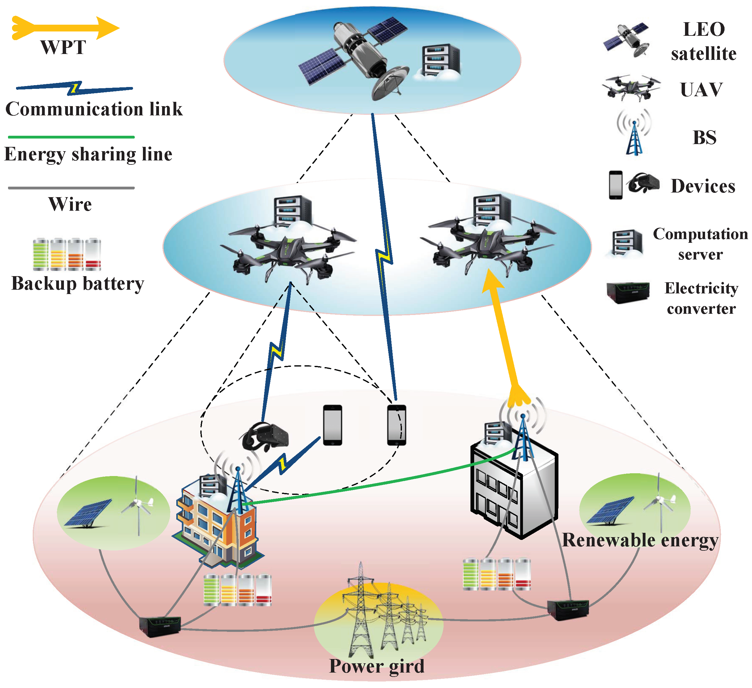
In this article, we first develop a SAGIN with a new designed power supply technology. In order to maintain the sustainability of the network, the BS explores the WPT to power the UAV. The UAV is able to dynamically adjust its trajectory to cope with task processing and charging. Joint the latency, energy consumption, and carbon emission is formulated the cost function. Obviously, our research target is to minimize the cost function.
The main contributions of this article can be summarized as follows:
We propose an architecture for SAGIN with a new designed power supply technology. This network offers ubiquitous connectivity while adapting to the requirements of high reliability and green communication.
We develop a cost function with a joint latency-oriented, energy consumption, and carbon emission, which facilitates to decrease the latency of task processing, the energy consumption and carbon footprint of the network through optimization.
We put forward a TD3PG method. This DRL-based algorithm is capable of sensing parameter changes in the network and dynamically updates the offloading decision.
We conduct experimental evaluations and comparisons. The proposed algorithm is compared with the other three benchmark algorithms. The results show that the proposed algorithm is outstanding in terms of reducing task latency, network energy saving, and lower carbon emision.
The rest of this article is organized as follows. In
Section 2, the system model with SAGIN is presented.
Section 3 provides the problem formulation. In
Section 4, a TD3PG algorithm is designed to obtain the optimal values.
Section 5 demonstrates the simulation results and performance analysis. Finally,
Section 6 devotes to the conclusions.
2. System Model
A SAGIN is considered, which consists of
M ground user devices,
N BSs,
K UAVs, and a low earth orbit (LEO) satellite. As shown in
Figure 1, each BS, each UAV, and the LEO satellite is separately equipped with a server for providing the devices with computation services. Devices are randomly distributed on the ground, which satisfy
. BSs are deployed on buildings of height
and satisfy
. The flight altitude of the UAV
k is fixed as
H. The communication range covers the preset range around itself, which satisfies
. It is assumed that a LEO satellite is available within the communication coverage at all times and the meteorological environment remains constant. The set of the time slot is indicated as
with the size of each time slot is
.
Each BS is independently equipped with solar panels, wind turbine, backup battery and electricity converter to provide uninterrupted energy supply. Adjacent BSs are able to share energy by energy sharing line. In order to maintain the stable operation of the UAV, the BS is able to supply the UAV with energy via WPT.
Given that virtual reality, augmented reality, and mixed reality are the typical applications based on the 6G [
27], it is assumed that each device has one total task which can be divided into a number of subtasks. The subtasks from device
m may be respresented as
, where
and
denote the subtask’s size (bit) and required CPU cycles per unit of data (cycles/bit) in time slot
t, respectively.
indicates the latency constraint for executing the subtask, which contains the latency for the transmission, computation, and waiting of the subtask. Subtasks follow a Poisson distribution with arrival rate
.
The relevant system models in SAGIN will be enumerated in the following.
2.1. Backup battery Model for BS
Denote
as the electrical load for BS
n in time slot
t, which is related to the communication traffic
[
28]. Hence,
can be expressed as
where
and
are coefficients.
The BS backup battery is required to reserve capacity
to meet the energy consumption for BS
n electrical load during the fixed standby time
in time slot
t.
can be represented as
During the time slot
t, the harvested energy from RE by
N BS backup batteries is
. The energy sharing to the adjacent BS is denoted as
. Let
denote the energy reserved by the backup battery to meet a fixed standby time at the current communication traffic of the BS.
is the energy consumption of each BS. Suppose the energy remaining in the backup battery is
. Then backup battery during the next time slot can be derivated as
where
is the backup battery capacity.
is the energy supplied by power grid when RE harvesting is unable to maintain the BS energy consumption, which can be constructed as
where
. Considering the cost and size of BS energy harvesting equipment, the optimal unit size is finitely large. On the other hand, battery lifetime
is an another factor to be considered, which is related to the number of charge/discharge cycles. In this case, the following constraints are required to be satisfied as
where
is the maximum electrical load for the BS. Define
as the cost-performance ratio of the backup battery, which is as large as possible.
and
denote the actual and the maximum expectation cost of the backup battery, respectively.
Furthermore, adjacent BSs are able to share energy by physical resistive power line connections to maximize RE utilization. This approach may be reasonable for energy sharing among BSs within small zones [
20]. The remaining energy of the RE may be shared with other BSs. Then the sharing energy
can be expressed as
where
is the RE transfer ratio with
. When the backup batteries are fully charged, the excess RE
will be discarded. Supposing that the loss factor for energy transfer between BSs is
, which satisfies
. Thus, the energy loss
can be expressed as
It is crucial to reduce energy loss in evaluating the reduction of carbon emission.
2.2. Communication Model
Each subtask can be offloaded to BS, UAV, or LEO satellites for execution in one of these ways in time slot t. Thereafter, the task communication model is described as follows.
2.2.1. Offloading to the BSs
Let
denotes the wireless transmission rate between device
m and BS
n in time slot
t, which can be expressed as
where
represents the channel bandwidth between device
m and BS
n.
is the transmission power of device
m.
is the path loss that is related to the distance
between device
m and BS
n in time slot
t.
is the small-scale channel fading subject to Rayleigh fading.
denotes the noise power.
is the interference from the other BSs.
2.2.2. Offloading to the UAVs
If device
m is in the communication coverage of UAV
k in time slot
t,
is assumed. Otherwise,
. As the altitude of the UAV is much higher than that of the devices, the line-of-sight channels of the UAV communication links are much more predominant [
29]. The wireless channel of the UAV is considered as a free-space path loss model. Thereby the channel gain
is
, where
denotes the channel gain at unit distance.
represents the path loss index.
is the Euclidean distance between the
m-
device and the
k-
UAV. Hence, the transmission rate
can be formulated as
where
is the channel bandwidth. The
represents the co-channel interference from all the other UAVs.
2.2.3. Offloading to the LEO satellite
The channel conditions between the LEO satellite and ground devices are mainly affected by the communication distance and rainfall attenuation. Since the distance between LEO satellite and device remains almost unchanged, a fixed transmission rate
between devices and the LEO satellite is adopted. It is usually lower than the tansmission rate between devices and UAV communication [
30,
31].
2.3. Computation Model
The task can be executed in four ways, executed locally, offloaded to BSs, offloaed to UAVs, or offloaded to the LEO satellite. Due to the small data size of the computation result, the delay and energy consumption for transmitting the computation result can be omitted [
32].
2.3.1. Local Computation
The device is capable of varying CPU cycle frequency
dynamically to obtain better system performance. Consequently, the latency of local task execution
can be obtained as
where
indicates the queuing delay of the task for the device. Assuming the energy consumption of per CPU cycle as
, where
is the CPU chip related switching capacitor [
33], the energy consumption
of the task execution at the device can be expressed as
2.3.2. Offloading to the BSs
The BS has a relatively stable energy supply and a powerful CPU. If tasks are offloaded to the BS, they will be executed instantly without queueing. Denote that
is the allocated computation resource for the
n-
BS. The task execution latency
for offloading to the BS can be given as
The energy consumption
of the task execution at the BS can be obtained as
2.3.3. Offloading to the UAVs
The task execution latency
for offloading to the UAV can be expressed as
where
is the allocated computation resource for the
k-
UAV.
Define
as the energy consumption per unit of computation resources of the UAV. The energy consumption
of the task execution at the UAV can be given as
2.3.4. Offloading to the LEO satellite
Denote that
is the allocated computation resource for the LEO satellite. The task execution latency
for offloading to the LEO satellite can be expressed as
The energy consumption
of the task execution at the LEO satellite can be obtained as
where
is the energy consumption per unit of computation resources of the LEO satellite.
2.4. WPT Model
In the case that UAV
k is within the BS
n energy transmission coverage in time slot
t,
. Otherwise,
. In order to maintain the sustainability of the network, the BS explores the WPT to power the UAV. Linear energy harvesting model is adopted. Then the harvested energy of the UAV
k can be expressed as
where
denotes the energy conservation efficiency, which satisfies
.
is the BS transmitting power.
and
are the antenna power gains of the BS transmitter and the UAV receiver, respectively.
is the channel gain between the
n-
BS and the
k-
UAV in time slot
t.
2.5. Flight Model
Continuous variables such as the average velocity
and the directional angle
are considered to adjust the trajectory of the UAV
k. Assuming that the horizontal position coordinates and the moving distance of UAV
k in current time slot are
and
, respectively. The position coordinates of UAV
k in the next time slot can be expressed as
Referring to [
34], the propulsion power consumption of UAV can be modeled as
where
and
are constants, representing the blade profile power and induced power in hovering status, respectively.
denotes the tip speed of the rotor blade.
is known as the mean rotor induced velocity in hover.
and
s are the fuselage drag ratio and rotor solidity, respectively.
and
A denote the air density and rotor disc area, respectively. The flight energy consumption of UAV
k in time slot
t can be given as
The system model in SAGIN are enumerated in this section. In the following section, the cost function will be constructed.
3. Problem Formulation
How to integrate latency-oriented, energy consumption, and carbon emission to model the objective function in SAGIN is the key to solve the first issue. According to the system model mentioned above, the cost function is first constructed on the basis of system model and then the formulation of the problem is demonstrated in this section.
The network cost function
is constructed by joint the total latency
, energy consumption
, and carbon emission
, which can be represented as
where
,
, and
represent the preference on latency, energy consumption, and carbon emission, respectively. And satisfy
.
,
, and
are expressed as
where
is the conversion factor of carbon emission per unit of energy and is related to the type of energy source.
,
,
, and
represent the time when the tasks are executed locally or offloaded to the computation server in time slot
t, respectively. In particular, each subtask can only be executed in one of these ways.
includes energy consumption for tasks execution and UAV flight in time slot
t.
is the reduction in carbon emissions through reducing traditional power gird energy consumption.
The network cost function is formulated into a minimization problem as the following.
Constraint (
26b) and (26b) imply that the task is indivisible and can be executed locally or remotely at the computation server. (26c) constrains the latency limit of the task. Constraint (26d) defines the range of angles and velocities that control the UAV’s flight trajectory. (26e) ensures that the safety distance among different UAVs, where
is the Euclidean norm. Constraint (26f) indicates that the minimum and maximum thresholds for the UAV and BS backup batteries, respectively. (26g) guarantees that the computation resources allocated to the task by the device and other computation servers do not exceed the maximum computation capacity. (26h) specifies the range of variables.
It is a challenge to solve the above problem, since the dynamic and complex characteristics of the network environment. It is crucial to design a satisfactory solution that is real-time and capable of handling high-dimensional dynamic parameters. Therefore, in the following section, DRL is used to learn network and to deal with optimization problem with various constraints.
4. Markov Chain Model based TD3PG Algorithm in SAGIN
DRL aims to learn award maximizing strategy by the interaction of intelligent agents with the environment. In order to solve the second issue with DRL, the cost function is reformulated as a Markov Decision Process (MDP). TD3PG, a DRL-based strategy, is proposed to optimize the objective problem by training the nearoptimal model.
4.1. MDP Formulation
A typical MDP with 4 elements tuple , where is the state space. is the action space. denotes the state transition function, which indicates the probability of the transition to next state after performing . is the reward function. The detail descriptions of the elements in the tuple are as follows.
State space: State space is designed to store the DRL agent’s observations in the environment and to guide the generation of actions. The state space includes the remaining energy of the UAV
, the BS
, the reserved energy for BS backup battery
, the current horizontal location of the UAV
, and the remaining amount of the current task
. Then the system state space can be defined as
Action space: Action space is designed to store the actions performed by the DRL agent in the environment in order to obtain feedback from the environment and the next state. The action space contains the offloading decisions
(i.e., offloading task to local device, BS, UAV, or the LEO satellite). The navigation speed
and the rotation angle
for controlling UAV trajectory are continuous value in the interval
and
, respectively.
denotes the dynamic computation resources of the device.
is the proportion of shared RE harvested by BS. Therefore, the system action space can be expressed as
Reward: Reward is the feedback from the environment to the DRL agent after performing the current action. The research goal is to minimize the cost function. The algorithm depends on the reward to evaluate its decisions by learning the SAGIN environment. Due to the fact that the goal of RL is a cumulative overall reward over time to maximize reward, the reward function is reformulated to be the negative value of the optimization cost function. Then the reward can be expressed as
where the coefficients
,
, and
in
U are required to satisfy
and
, respectively.
4.2. TD3PG Algorithm
Owing to the fact that the action space contains continuous variables, TD3PG is adopted, which is an off-policy algorithm based on the actor-critic structure for dealing with the optimization problems with the high-dimension action space [
35].
Compared to the conventional actor-critic based deep deterministic policy gradient (DDPG), which would result in cumulative errors. TD3PG solves the former overestimation problem. It has two pairs of critic networks in which the smaller Q value of the two Q-functions is chosen to form the loss function in the Bellman equation. Hence, there is less overestimation in learning process. Moreover, the application of delayed policy technique enables TD3PG to less frequently update the actor network and the target network than the critic networks. In other words, the model does not update policy unless the model’s value function is updated sufficiently. The less frequent policy updates will bring a value evaluation with lower variance and produce a better policy [
36].
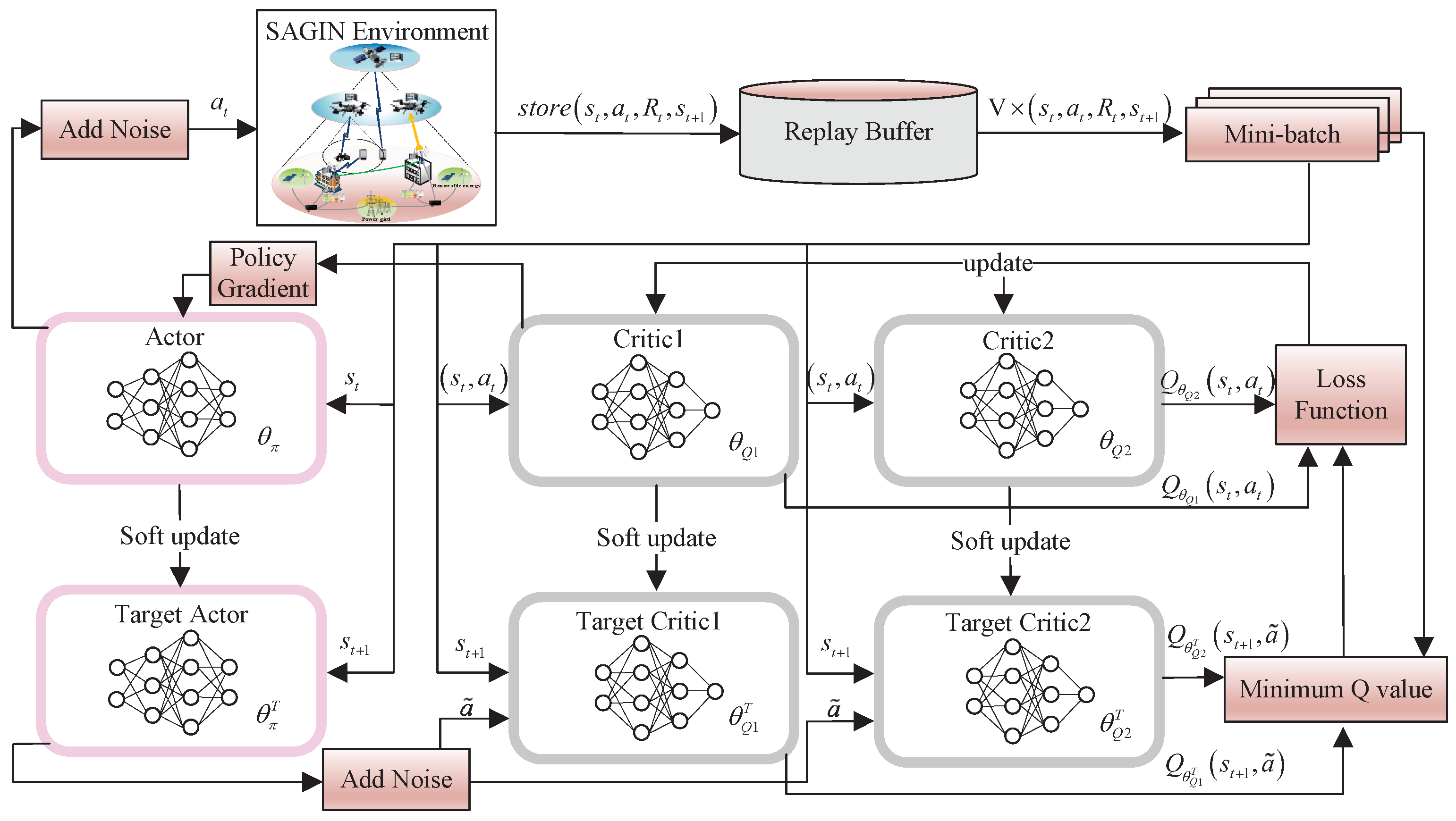
Apart from the above, TD3PG is also able to smooth the value estimate by applying a smoothing technique for target policy that adds noise ( clipped random noise) to the target actions and average over mini-batches, as shown in
According to the structure of the TD3PG algorithm depicted in
Figure 2, the TD3PG architecture contains one actor network and two critic networks. The actor network is parameterized by
, and two critic networks by
and
, respectively.
The agent firstly observes the current state and picks an action via the actor network. After performing in the environment, the agent is able to observe the immediate reward and the next state . Then, the agent will select the policy that maximizes the cumulative reward, which converts the state to the action . At this point, the transition is obtained and stored in the replay memory for further sampling.
The training process of the TD3PG algorithm is summarized as Algorithm 1.
|
Algorithm 1 TD3PG algorithm. |
Require: Training episode length: -. discount factor: .
Ensure: Loss, gradients.
- 1:
Initialize the actor network with parameter . Initialize the critic network , with parameters and , respectively. - 2:
Initialize the target network by: , , . - 3:
Initialize replay buffer . - 4:
for episode = 1 to - do
- 5:
Reset simulation parameters and obtain initial observation state s. - 6:
for t = 1 to T do
- 7:
Get action after adding exploration noise . - 8:
Obtain the reward and update . - 9:
Store the transition in replay buffer . - 10:
Sample a random mini-batch of V tuples from replay buffer . - 11:
Compute greedy actions for next states through , where . - 12:
Compute target value based on Eq. ( 31). - 13:
Update the critics by minimizing the loss function Eq. ( 32). - 14:
Update the actor network parameter by using the sampled policy gradient Eq. ( 34). - 15:
Update the target networks Eq. ( 35). - 16:
end for
- 17:
end for
|
The minimum Q-value estimate of these two critic networks is used to calculate the target value
, which can be obtained by
where
is a discount factor, ranging from 0 to 1.
The loss function of two critic networks can be defined as
Then the gradient of loss function is calculated as
The policy gradient of the actor network can be given as
The parameters of the target networks will be updated by means of
where
is a step size coefficient and satisfies
.
4.3. Complexity Analysis
The proposed TD3PG algorithm contains both actor network and critic network. Therefore, the complexities of them are evaluated separately. Assuming that the actor network has
layers with
neuron nodes in the
l-
layer. Then the complexity of the
l-
layer is
[
37]. The complexity of the actor network is
. Assuming that the critic network has
layers with
neuron nodes in the
j-
layer, the complexity of the
j-
layer is
[
37]. Similarly, the complexity of the critic network is
. Hence, the overall computational complexity of the TD3PG algorithm is
, which is similar to that of the DDPG algorithm. In general, TD3PG algorithm is an improvement for DDPG algorithm, but it does not increase the complexity much.
