Preprint
Article

A New Approach to the Preparation of Stable Oxide-Composite Cobalt-Samarium Catalysts for the Production of Hydrogen by Dry Re-Forming of Methane

Altmetrics

Downloads

136

Views

55

Comments

0

A peer-reviewed article of this preprint also exists.

Submitted:

04 July 2023

Posted:

05 July 2023

You are already at the latest version

Alerts
Abstract
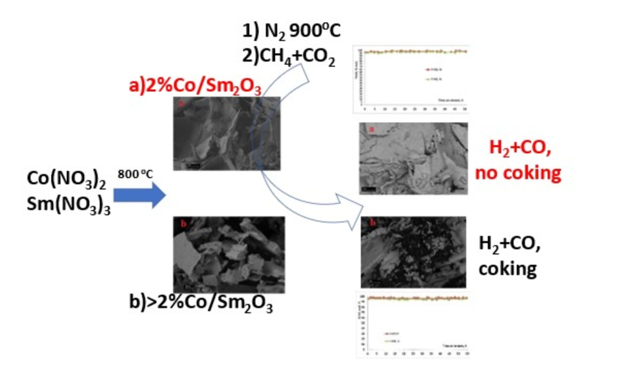
A new approach to preparing a series of Co/Sm2O3 catalysts for hydrogen production by dry re-forming of methane (DRM) is developed. The catalysts precursors are synthesized by a simple method, including evaporation of aqueous solutions of cobalt and samarium nitrates, followed by a short-term calcination of the resulting material. The as-prepared and spent catalysts are characterized using X-ray diffraction (XRD), scanning electron microscopy (SEM), transmission electron microscopy (TEM), temperature-programmed reduction (H2-TPR), and thermogravimetric analysis (TGA). It is shown that the content of cobalt in the synthesized materials affects their phase composition and carbonization resistance in the DRM reaction. It is demonstrated that preheating under N2 affords catalysts providing stable hydrogen and CO yields of 94-98 % for at least 50 h at 900°C. These yields are among the highest ones currently available for DRM catalysts derived from Co-Sm complex oxides. It is found that reduction in the amount of cobalt in the catalyst and its preheating to an operating temperature of 900°C in a nitrogen flow con-tribute to preventing catalyst carbonization and metal particles sintering.
Keywords: 
Subject: Chemistry and Materials Science  -   Materials Science and Technology

1. Introduction

The increasing threat of global climate change has prompted the governments of 195 countries to adopt the “Paris Agreement” that aims to reduce greenhouse gas emissions, primarily by decarbonizing the economy [1,2]. In this regard, hydrogen is considered the most environmentally friendly alternative fuel, since its use as a fuel is accompanied only by the release of water vapor into the air. Hydrogen has the highest energy intensity per unit mass but low density. In addition to being a promising fuel, hydrogen is used in increasing volumes in the processes of ammonia synthesis and oil refining and as a synthesis gas component for the production of methanol and a number of petrochemicals [1,2,3,4].
The main industrial process of hydrogen production is the steam reforming of methane (1), which a high-energy endothermic process requiring the production of considerable volumes of water vapor [2,5,6].
СН42O⇌СО+3Н2    ΔH0298= +206 kJ
Promising processes for hydrogen production from methane are partial oxidation of methane, POM, (2) and dry reforming of methane, DRM, (3).
2СН4 + O2⇌ 2СО + 4Н2    ΔH0298= –36 kJ
СН4 + СО2 ⇌ 2СО + 2Н2    ΔH0298= +247 kJ
Since reaction (2) is exothermic, the POM process in combination with the steam reforming of methane is implemented in the autothermal mode. In addition, POM allows the production of synthesis gas (H2: CO = 2:1) suitable for direct processing into petrochemical products [5,6,7,8]. The practical application of POM is largely limited by the need to use pure oxygen, the related explosion hazard, and the possible sintering of metal active centers in the event of "hot spots" in the catalyst layer.
The process of hydrogen production by the DRM reaction has been most extensively studied in recent decades. For example, the number of publications on this topic in 1990-2022 exceeded 1000, including 863 scientific articles with the citation number above 6, and 34 reviews [9]. The explosive interest in this topic is due to a number of factors. Firstly, these are the above-mentioned efforts of most countries to reduce the greenhouse effect [1,2,3]. The DRM process allows the utilization of methane and carbon dioxide, which are the main greenhouse gases. Secondly, the DRM process is a way to produce hydrogen and other valuable products by processing of renewable raw materials, biogas, one of the promising decarbonization strategies [10]. Thirdly, the industrial process of hydrogen production by the steam reforming of methane includes an additional stage of the steam reforming of CO (4):
CO + H2O ⇌ CO2 + H2
CO2 generated by this process must also be disposed of.
In addition, the joint methane steam reforming and DRM can also be used for the utilization of CO2 captured from the flue gases of methane steam reforming plants [2]. Finally, the DRM process renders it possible to produce synthesis gas, which is a suitable intermediate for the synthesis of dimethyl ether, Fischer-Tropsch synthesis of hydrocarbons etc. [1,2,3,4,6,9,11,12,13,14,15,16]. Furthermore, the synthesis gas of the DRM process can be used in fuel cells [13].
As for the use of the DRM process is practice, this process is realized mostly on a pilot scale and in combination with the steam reforming of methane in order to control the composition of the resulting synthesis gas [15,16,17,18]. The CALCOR process is known [15,16,17,19]; however, it is aimed at obtaining primarily carbon monoxide (H2:CO = 0.42:1) and, therefore, is accomplished at a large excess of CO2. The industrial implementation of DRM is constrained by a number of features of this process, such as high endothermicity associated with the stability of CO2 and CH4 molecules and a significant formation of coke deposits and "sintering" of active catalyst centers associated with a high temperature of the process. A high temperature of the process also requires complex hardware design. In addition, it was shown that the DRM process conducted at elevated pressures is accompanied by an enhanced carbonization of catalysts. Therefore, the synthesis gas produced by DRM and intended for subsequent processing will require a costly stage of its compression [1,13,15,17,20,21,22].
According to thermodynamic calculations, at fairly low temperatures DRM does not allow a high yield of synthesis gas. To achieve high yields of synthesis gas (H2 : CO = 1 : 1) by reaction (3) with the reagents conversion close to 100% and reduced carbon formation by the methane pyrolysis reaction (5), a ratio of CO2 : CH4 = 1 : 1, a temperature above 850°C, and atmospheric pressure are required [12,13,16,17,22,23,24,25].
CH4 ⇌ C + 2H2    ΔG0298 ≤ 0 at T≥ 658 C.
These conditions also contribute to the reverse water gas shift reaction (6) that affects the ratio of DRM products and the value of CO2 conversion:
CO2 + H2 ⇌ CO + H2O    ΔG0298 ≤ 0 at T ≥ 700 C.
Carbon formation in the DRM process is possible not only by reaction (5) but also by the disproportionation of CO (7) and the hydrogenation of CO (8) and CO2 (9) [12,26].
2СО ⇌ С+ CO2   ΔH0298= -172 kJ
СO+Н2⇌С+Н2О   ΔH0298= -131 kJ
СO2+2Н2⇌С+2Н2О   ΔH0298= -90 kJ
However, these reactions are exothermic, thermodynamically unfavorable at high temperatures, and probably proceed in the opposite direction.
One of the key approaches to the practical implementation of the DRM process considered in most relevant publications is to design selective, stable, and carbonization resistant catalysts. Objectives are to prevent sintering of the active centers of catalysts and formation of stable forms of surface carbon (graphite, carbon fibers, and nanotubes), which deactivate active centers, destroy the catalyst, and block the passage of gases through a reactor. Complex oxides of the perovskite structure are in most common use as promising DRM catalysts [1,2,3,5,6,10,11,12,13,14,15]. As a result of pre-reduction or contact with reagents perovskite structure catalysts are transformed into composites containing a metal phase highly dispersed in an oxide matrix, which in some cases enables one to achieve high activity, selectivity, and stability in DRM. Among these compounds, there are catalysts based on nickelates and cobalates of rare earth elements [5,11,27,28,29,30,31,32,33]. According to these studies, perovskite precursors of catalysts can be synthesized by various methods, such as solid-phase synthesis, self-propagating high-temperature synthesis, sol-gel synthesis, decomposition of specially synthesized complex compounds, etc. The choice of the synthesis method largely determines the properties of the DRM catalysts.
Previously, we synthesized and tested in DRM lanthanum nickelate [30] and samarium cobaltate [29] perovskite structures obtained by the thermal decomposition of specially synthesized heterometallic complex compounds (M1(phen)x][M2(NO3)y(H2O)]·zMeCN, where M1 is Ni or Co, M2 is La or Sm, phen is o-phenanthroline, and MeCN is methyl acetate). These compounds served as precursors of efficient DRM catalysts, composites containing metallic nickel or cobalt dispersed in a matrix of lanthanum or samarium oxides. However, during the DRM process, despite the thermodynamically favorable conditions of the process, their surface was subjected to significant carbonization which resulted in blocking of the gas flow in the reactor. Using a complex procedure for the supercritical antisolvent deposition of a complex compound--the precursor of perovskite SmCoO3, the catalyst particle size was reduced and catalyst carbonization was avoided [29].
However, we have shown that the production of efficient DRM catalysts does not require the mandatory synthesis of a completely single-phase initial perovskite [34,35]. Composites containing, along with the perovskite phase, the phases of nickel, cobalt, and rare earth elements oxides can be synthesized using a simple evaporation of aqueous solutions of nickel, cobalt and rare earth elements (REE) salts. In the DRM process, these composites form catalysts consisting of metallic nickel or cobalt dispersed in an REE oxide. These catalysts make it possible to obtain synthesis gas with a yield above 90% but undergo significant carbonization.
In order to create a DRM catalyst less susceptible to carburization, we synthesized an oxide composite containing 2 wt. % cobalt. This material was prepared by the simple evaporation of an aqueous solution of cobalt and samarium nitrates, followed by calcination of the resulting material at 700oC [36]. It was assumed that due to a decrease in the cobalt content in this material compared to the SmCoO3 perovskite containing 23 wt. % cobalt metallic cobalt particles more resistant to sintering and subsequent carbonization would be obtained. It is known that the deposition of perovskite systems on various substrates often increases their efficiency in DRM catalysis [11,14,16,20]. It was supposed that the synthesized material would contain samarium cobaltate SmCoO3 dispersed in a matrix of samarium oxide. However, the formed composite consisted of samarium oxide and samarium cobaltite, Sm2CoO4, which apparently resulted from the interaction of SmCoO3 with an excess of samarium oxide.
It was found that this material after prereduction in CH4 and CO2 mixture or in hydrogen flow formed catalyst which demonstrated low efficiency in DRM. And only after a long-term exposure in the CH4/CO2 flow showed synthesis gas yields of 88-90 % at 900°C.
The aim of the present study is to find optimal conditions for the preparation of highly efficient stable and carbonization resistant Co/Sm2O3 catalysts with various cobalt content for hydrogen production by DRM.

2. Materials and Methods

2.1. Materials

We used the following commercial Sigma-Aldrich reagents: Co(NO3)2·6H2O CAS 10026-22-9, and Sm(NO3)3·6H2O CAS 13759-83-6.

2.2. Preparation of Catalyst

The designations of the synthesized materials--catalysts precursors--and the amounts of reagents used for their synthesis are given in Table 1. The amounts of reagents corresponded to the cobalt content in the resulting catalyst (Table 1). The Co(NO3)2•6H2O and Sm(NO3)3•6H2O samples were dissolved in 30 ml of distilled water under stirring in a glass beaker. The obtained solutions were heated under stirring until water evaporation. The resulting mass was transferred into an alundum crucible and heated in a Nabertherm muffle furnace for 3 h at 300oC. The solid product was crushed, heated in the muffle furnace for 2.5 h to 800oC, and kept for 2 h at this temperature.

2.3. Characterization

The specific surface area SBET of the samples was measured by the method of low-temperature nitrogen adsorption on an ATKh-06 analyzer (Katakon, Russia). The samples were degassed in a nitrogen flow (1 atm) at 200oC for an hour prior to analysis. Based on the data obtained, the specific surface area of the samples was calculated using the Brunauer–Emmett–Teller (BET) model and the five-points method in the partial pressure range of 0.05–0.25 P/P0.
The powder X-ray diffraction study (XRD) of freshly prepared and spent catalysts was carried out on a Rigaku MiniFlex 600 diffractometer (CuKα radiation, detector with graphite monochromator, and Cu anticathode). The XRD data were processed using the database of the International Center for Diffraction Data (ICDD).
Thermogravimetric analysis (TGA) was performed on a TGA/DSC 3+ simultaneous thermal analyzer (Mettler Toledo) in an air flow in the range of 30–1000°C at a heating rate of 10°C/min. The TGA data were processed using the STARe Excellence software.
The micromorphology of all samples was studied by scanning electron microscopy (SEM) on a Carl Zeiss NVision 40 high-resolution microscope equipped with an Oxford Instruments X-MAX detector (80 mm2) and operating at an accelerating voltage of 1-20 kV. SEM images were taken in InLens (SE2) and ESB modes with an Everhart-Thornley detector at accelerating voltages of 1 and 7 kV.
The microstructure and elemental mapping of some spent catalysts were investigated on a TJEOL JEM-2100 UHR transmission electron microscope (TEM) operating at an accelerating voltage of 200 kV. Sample powders were dispersed in ethanol and dropped onto a TEM cooper grid (Ted Pella, Inc.). TEM micrographs were collected in the bright-field mode using an Olympus Quemesa 11-megapixel CCD camera. The dark-field sample images and elemental mapping were performed in the STEM mode.
The temperature-programmed reduction (H2-TPR) was performed in a flow quartz reactor with an inner diameter of 2 mm at a heating rate of 7.5°C/min. Temperature was measured with the aid of a chromel-alumel thermocouple (K-type). The Н2/Ar flow (5 vol. % H2) velocity was 50 ml/min. The H2 content in the outlet gas flow was assessed on a Krystallyuks-4000M chromatograph equipped a thermal conductivity detector.
In addition, the H2-TPR of the catalysts was carried out in the same mode on an USGA-101/M3 chemisorption analyzer (LLC UNISIT, Russia).

2.4. Catalytic Experiments

The catalytic performance of 2%Co/Sm2O3, 5%Co/Sm2O3, 10%Co/Sm2O3, 23%Co/Sm2O3 materials in the DRM process was tested at atmospheric pressure in a fixed bed flow quartz reactor (inner diameter 18 mm) with an axial pocket for thermocouple (outer diameter 8 mm). The tip of the thermocouple (chromel-alumel (K)) was positioned in the center of the catalyst layer. Powdered catalysts precursors were pressed into pellets, grinded, and a fraction with 0.5-1 mm grains was used in further experiments. The catalyst precursor (0.2 g, layer height 1 mm) was placed on a quartz fiber substrate. The catalyst precursor was heated to 900 oC in a nitrogen stream (JSC NIIKM, Russia, nitrogen content 99.999%). When the catalyst was heated in the nitrogen flow, after its supply was stopped, a gas mixture of CH4 and CO2 (JSC "Moscow Gas Processing Plant", Russia, purity at least 99.9%) was fed into the reactor. The ratio of CH4 : CO2 was 1, and the feed rate of the nitrogen or gas mixture was 15 L × g−1 × h−1. The gas velocity at the reactor inlet and outlet was measured with a foam flow meter. The temperature change in the reactor was carried out using a programmable temperature controller. The products were analyzed at a fixed temperature, and the temperature was adjusted to other set values without stopping the supply of reagents.
The composition of gaseous products was analyzed online by GLC on GALS 311 chromatographs equipped with thermal conductivity detectors using He as a carrier gas. The concentrations of H2, CH4, and CO were estimated at 30°C in a 2 m × 3 mm steel column packed with NaX zeolite. The H2 concentration was calculated using a special calibration graph. To detect CH4, CO2, ethylene, and ethane a similar column filled by a Porapak Q at 70°С was used. The admixtures of C2+ hydrocarbons were determined at 70°C using a similar column filled by 5% Na2CO3 on alumina. The chromatographic data were analyzed using the EKOCHROM software (SKB of the Zelinsky Institute of Organic Chemistry, Russian Academy of Sciences). All chromatograms were calculated by internal normalization with correction made for the molecular weights of the components.

2.4.1. Calculations

Methane conversion, X(CH4), was calculated as
Χ ( C H 4 ) = W i n ( C H 4 ) W o u t ( C H 4 ) W i n ( C H 4 ) × 100 % ,
where Win(CH4) is the quantity (mol) of CH4 injected in the reactor and Wout(CH4) is the quantity (mol) of CH4 at the reactor outlet.
CO2 conversion X(CO2) were calculated similarly.
Hydrogen yield, Y(H2), was calculated as
Y ( H 2 ) = W o u t ( H 2 ) 2 W i n ( C H 4 ) × 100 % ,
where Wout(H2) is quantity (mol) of H2 at the reactor outlet and Win(CH4) is the quantity (mol) of CH4 injected in the reactor.
CO yield, Y(CO), was calculated as:
Y ( C O ) = W o u t ( C O ) W i n ( C H 4 ) + W i n ( C O 2 ) × 100 %
where Wout(CO) is the quantity (mol) of CO at the reactor outlet and Win(CH4) and Win(CO2) are, accordingly, the quantities (mol) of CH4 and CO2 injected in the reactor.

3. Results and Discussion

In specially blank experiments conducted in the reactor without a catalyst, a slight carbonization of reactor walls was detected mainly after a layer of quartz nozzle and quartz fiber. At the same time, the trace amounts of CO and hydrogen were recorded in exhaust gases along with unreacted reagents.

3.1. Characterization of freshly prepared materials

According to the XRD data, the synthesized sample of 2%Co/Sm2O3 contains phases Sm2O3 (ICDD 96-101-0341, 88 wt. %) and Sm2CoO4 (ICDD 96-200-2267, 12 wt. %) (Figure 1a). The phase content was calculated by the Rietveld method [37].
Sample 5%Co/ Sm2O3 (Figure 1b), along with Sm2O3 (ICDD 96-101-0341, 86 wt. %), contains the SmCoO3 phase (ICDD 96-412-4856, 14 wt. %).
Sample 10%Co/ Sm2O3 (Figure 1c), along with Sm2O3 (ICDD 99-208-1967, 47 wt. %), contains SmCoO3 (ICDD 99-204-5928, 53 wt. %).
Sample 23%Co/ Sm2O3 (Figure 1d), in which the amount of cobalt corresponds to its content in the SmCoO3 perovskite, according to XRD data, contains only 35 wt. % of SmCoO3 (ICDD 96-152-1745), as well as Sm2O3 (ICDD 96-101-0590, 42 wt. %) and Co3O4 (ICDD 96-153-8532, 23 wt. %). Thus, the samarium/cobalt ratio in the synthesized complex oxides significantly affects their phase composition.
The SEM images of the synthesized materials (Figure 2 a-d) show that the 2%Co/Sm2O3 sample (Figure 2a) is formed by flat particles with an undeveloped porous structure, which corresponds to a low specific surface area of the sample (Table 1).
In the images of 5%Co/Sm2O3 (Figure 2b) and 23%Co/Sm2O3 (Figure 2d) samples taken at a higher resolution, particles of a similar shape are seen; their lateral faces contain mesopores with a diameter of about 20 nm.
The 10%Co/Sm2O3` (Figure 2b) sample also contains flat particles with the undeveloped porous structure.
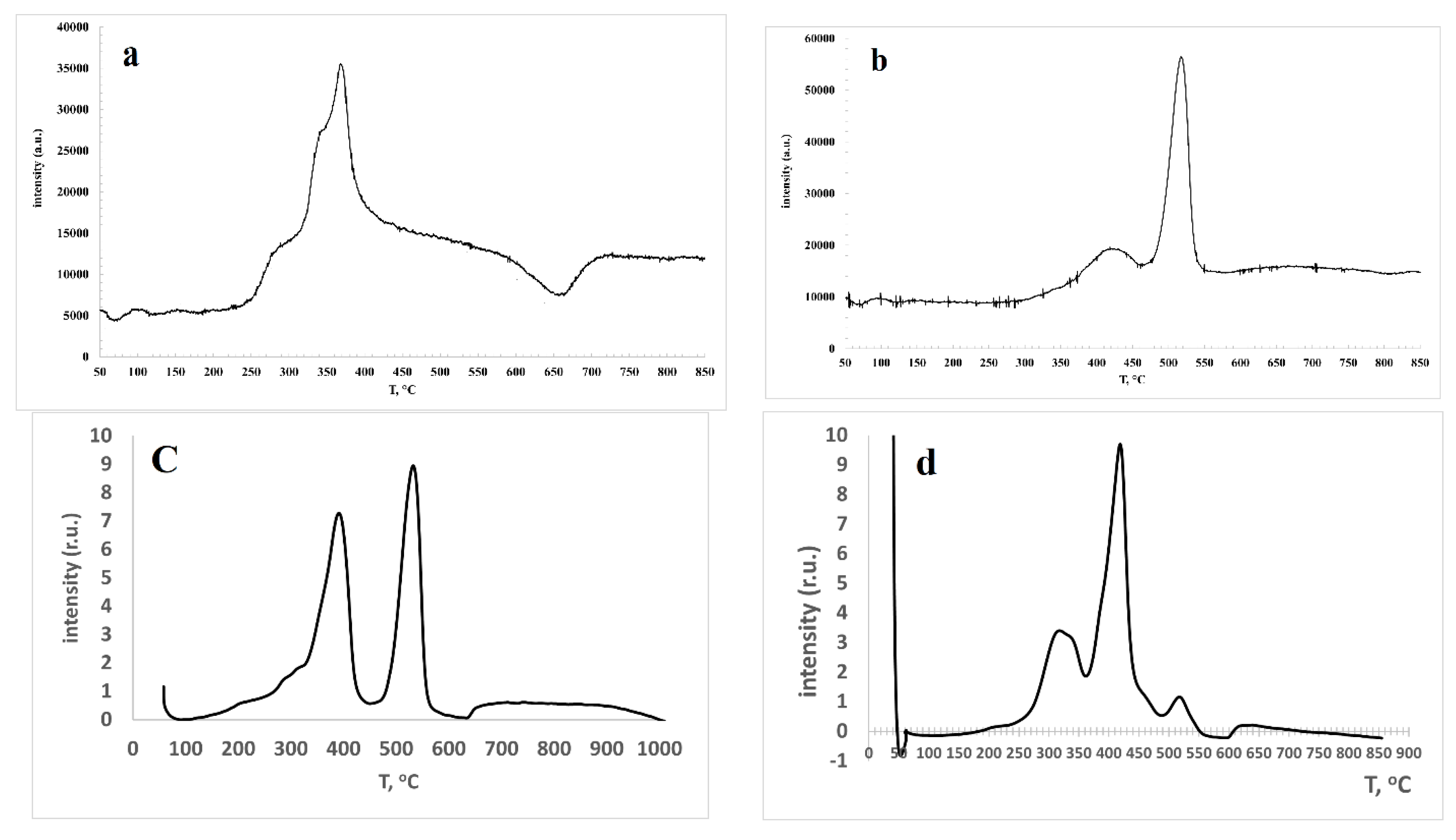
The H2-TPR profile of 2%Co/Sm2O3 (Figure 3a) reveals the presence of three regions of hydrogen absorption. Less intense peaks with maxima at 310 and 400oC are probably related to reduction of a small amount of Co3O4 contained in the catalyst [38], which was not recorded by XRD. An intense peak with a maximum at 540oC, according to [11,31,39], can be assigned to the reduction of samarium cobaltite by reaction (10):
Sm2CoO4 + H2 = Sm2O3 + Co + H2O.
The H2-TPR profile of 5%Co/Sm2O3 (Figure 3b) exhibits a low-intensity peak with maxima at 420oC and an intense peak with a maximum at 530 oC, which, according to [11,31,39], can be attributed to the staged reduction of samarium cobaltate by reactions (11) and (12):
2SmCoO3 + H2 = 2SmCoO2,5 + H2O
2SmCoO2,5 + 2H2 = Sm2O3 + 2Co + 2H2O
The H2-TPR profiles of 10%Co/Sm2O3 (Figure 3c) and 23%Co/Sm2O3 (Figure 3d) are recorded by the USGA analyzer. The H2-TPR profile of 10%Co/Sm2O3 shows two intense peaks with maxima at 390 and 532oC, which, according to [11,31,39], can also be attributed to the staged reduction of samarium cobaltate by reactions (11) and (12).
The H2-TPR graph of 23%Co/ Sm2O3 exhibits a peak with a maximum at 318oC corresponding to the reduction of cobalt oxides and an intense peak with a maximum at 419oC, which can be assigned to the reduction of both cobalt oxides and samarium cobaltate by reaction (11). A less intense peak with a maximum at 517oC probably corresponds to reaction (12). In general, the H2-TPR data obtained for the synthesized samples are consistent with the XRD analysis (Figure 1 and comments).

3.2. Results of Catalytic Experiments

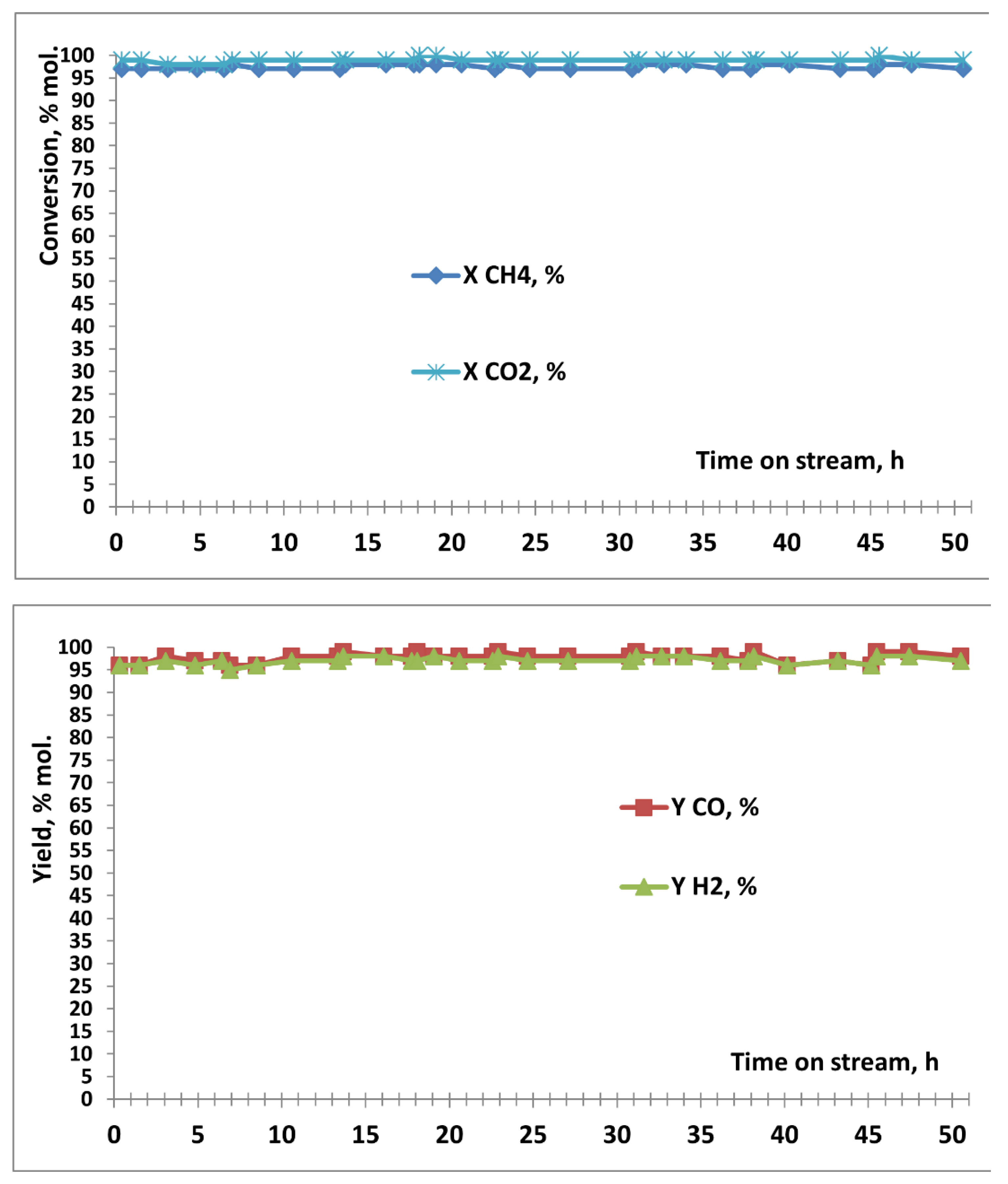
As indicated in our previous paper [36], it takes a long time for the 2%Co/Sm2O3 catalyst preheated to 900oC in the flow of CH4/CO2 (1 : 1) or hydrogen flow to reach the optimal operating mode. In the present work, 2%Co/Sm2O3 was preheated to 900 oC for an hour in a high-purity nitrogen flow. The results are shown in Figure 4.
It can be seen that in contrast to [36] results, immediately after the mixture of CH4 and CO2 was fed to the reactor, the yield of the synthesis gas (CO : H2 = 1 : 1) equal to 96 was achieved. The conversion of CH4 was 97%, and the conversion of CO2 was 99%. In a long-term experiment with intermediate cooling and reheating to 900oC in the high-purity nitrogen, the stable performance of the catalyst for 50 h was observed. The values of CO2 conversion and CO yield higher than the values of methane conversion and hydrogen yield are apparently due to an insignificant reverse water gas shift reaction (6) along with the DRM reaction (3). Since, in accordance with [36], in the case of the 2%Co/Sm2O3 catalyst, a decrease in temperature leads to a decrease in the conversion of reagents and the yields of products, this catalyst was not tested at temperatures less than 900oC. Our results demonstrate that a highly efficient and stable DRM catalyst is formed in situ immediately after the contact of 2%Co/Sm2O3 preheated to 900 oC in N2 flow with the CH4-CO2. mixture.
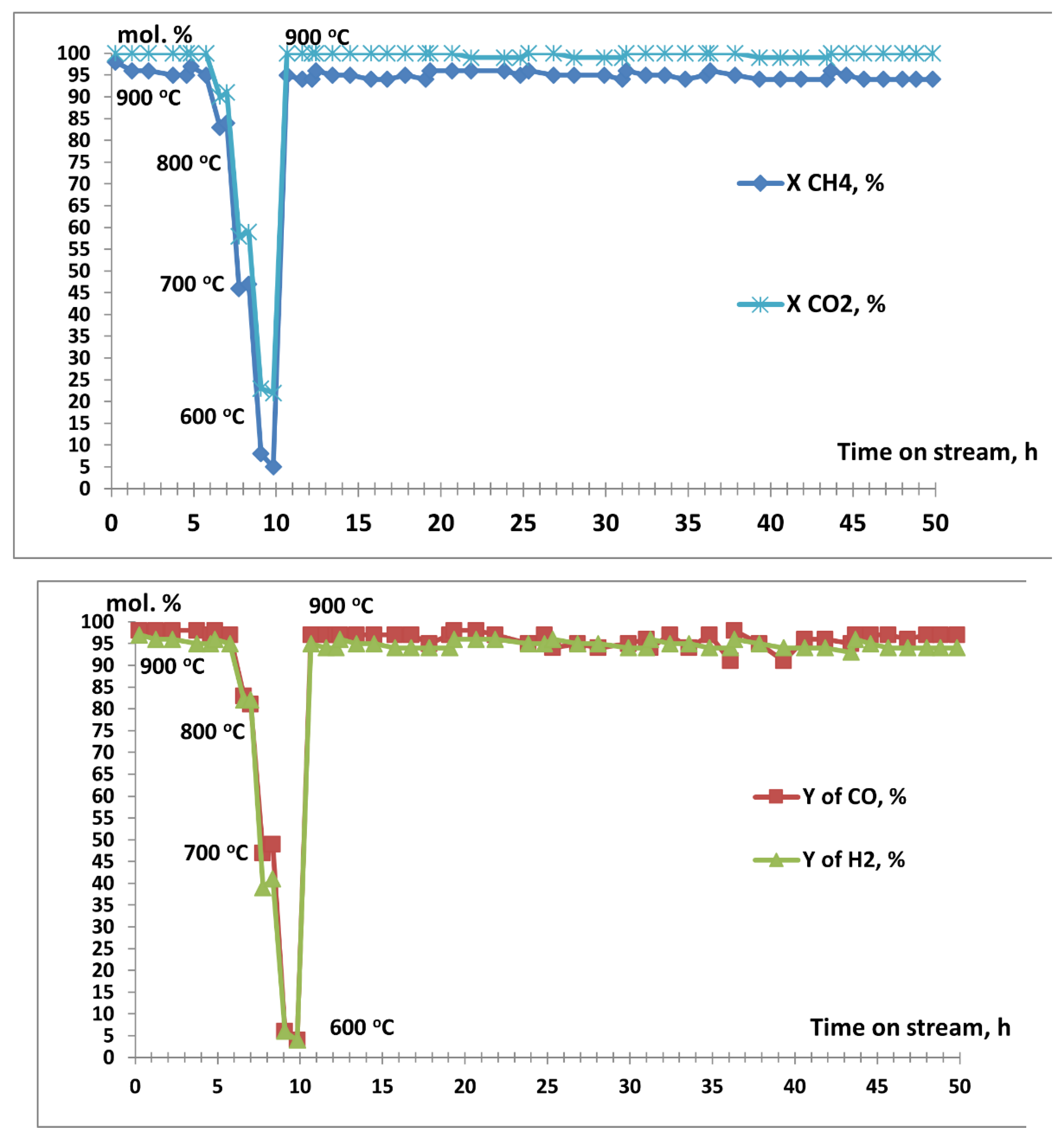
The 5%Co/Sm2O3 and 10%Co/Sm2O3 samples, which were also preheated to 900oC for an hour in the high-purity nitrogen flow, as well as the 2%Co/Sm2O3 sample, also immediately formed catalysts which showed high yields of CO and H2 (Figure 5 and Figure 6).
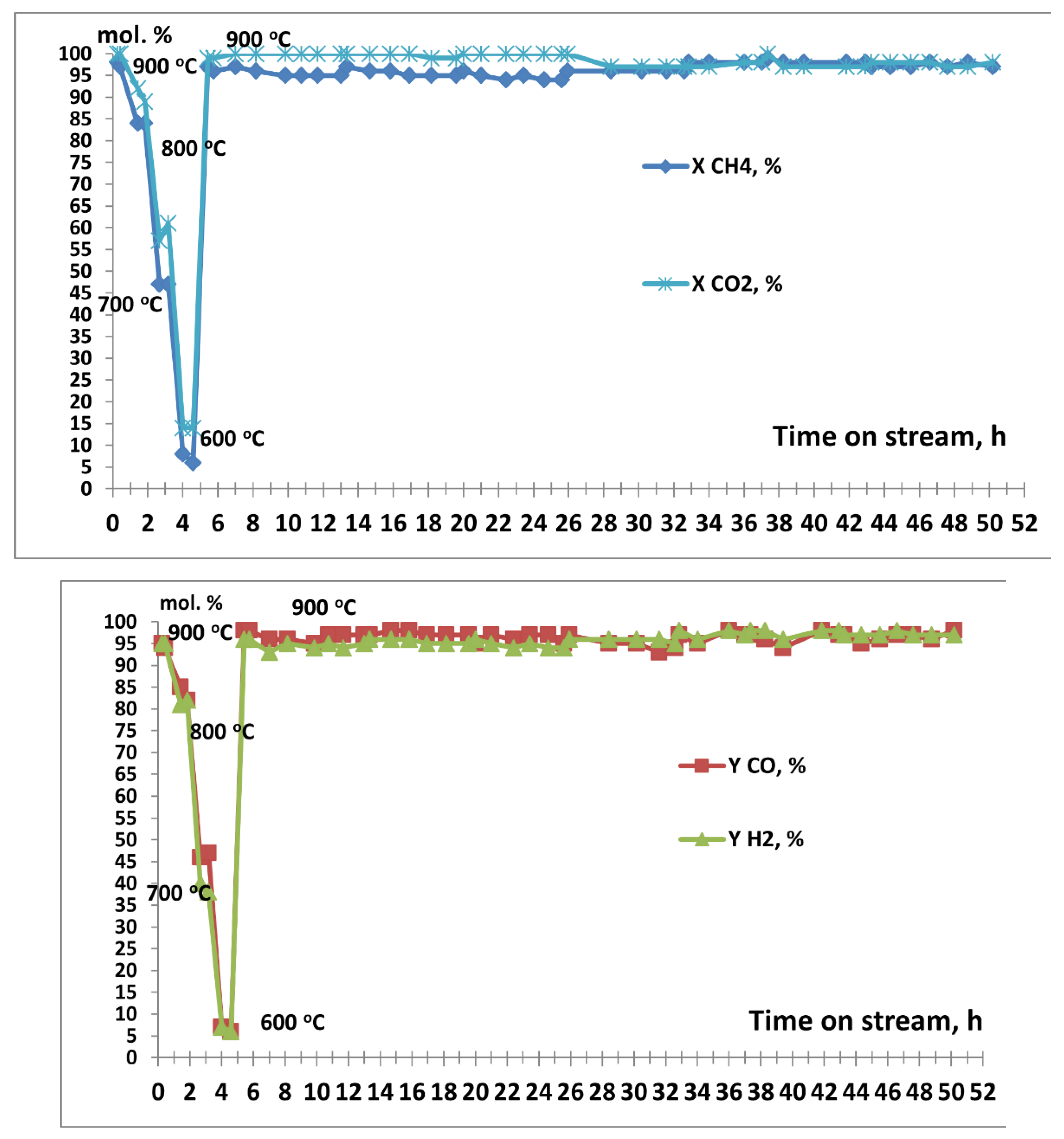
The data in Figure 5 indicate that for the catalyst derived from 5%Co/Sm2O3 the CH4 conversion is 95-98%, the CO2 conversion is 100%, the CO yield is 97-98%, and the H2 yield is 95-97%. When temperature was reduced to 800°C, the CH4 conversion decreased to 83-84%, the CO2 conversion decreased to 90-91%, the CO yield decreased to 81-83%, and the H2 yield decreased to 82%. At 700oC, the CH4 conversion was 46-47%, the CO2 conversion was 58-59%, the CO yield was 47-49%, and the H2 yield was 39-41%, while at 600oC almost no DRM was observed. A subsequent increase in temperature to 900oC restored the activity of the catalyst. When the experiment was continued up to 50 h, high values of CH4 conversion (94-96%), CO2 conversion (99-100%), CO yield (94-97%), and H2 yield (94-96%) were maintained. The observed values of CO2 conversion and CO yield higher than those of methane conversion and hydrogen yield also indicate that, along with the DRM reaction (3), an insignificant reverse water gas shift reaction (6) occurs and its contribution increases with decreasing temperature.
According to Figure 6, the catalyst derived from 10%Co/Sm2O3 demonstrates similar results in the DRM reaction. After initial heating in nitrogen flow to 900oC, and the subsequent supply of a mixture of CH4 and CO2 to the reactor, the CH4 conversion achieves 97-98% and the CO2 conversion is as high as 100%. The CO and H2 yields are 94-95 and 95%, respectively. When temperature was reduced to 800 C, the CH4 conversion decreased to 84%, the CO2 conversion decreased to 89-92%, the CO yield decreased to 82-85%, and the H2 yield decreased to 81-82%. At 700oC a CH4 conversion of 47%, a CO2 conversion of 57-61%, a CO yield of 46-47%, and a H2 yield of 38-40% were observed, while at 600oC almost no DRM occurs. The subsequent increase in temperature to 900°C also restores the activity of the catalyst. When the experiment was continued to 50 h, the high values of CH4 conversion (94-98%), CO2 conversion (97-100%), CO yield (95-98%), and H2 yield (94-98%) were maintained. The higher values of CO2 conversion and CO yield are also consistent with an insignificant occurrence, along with the DRM reaction (3), of the reverse water gas shift reaction (6), the contribution of which increases with decreasing temperature.
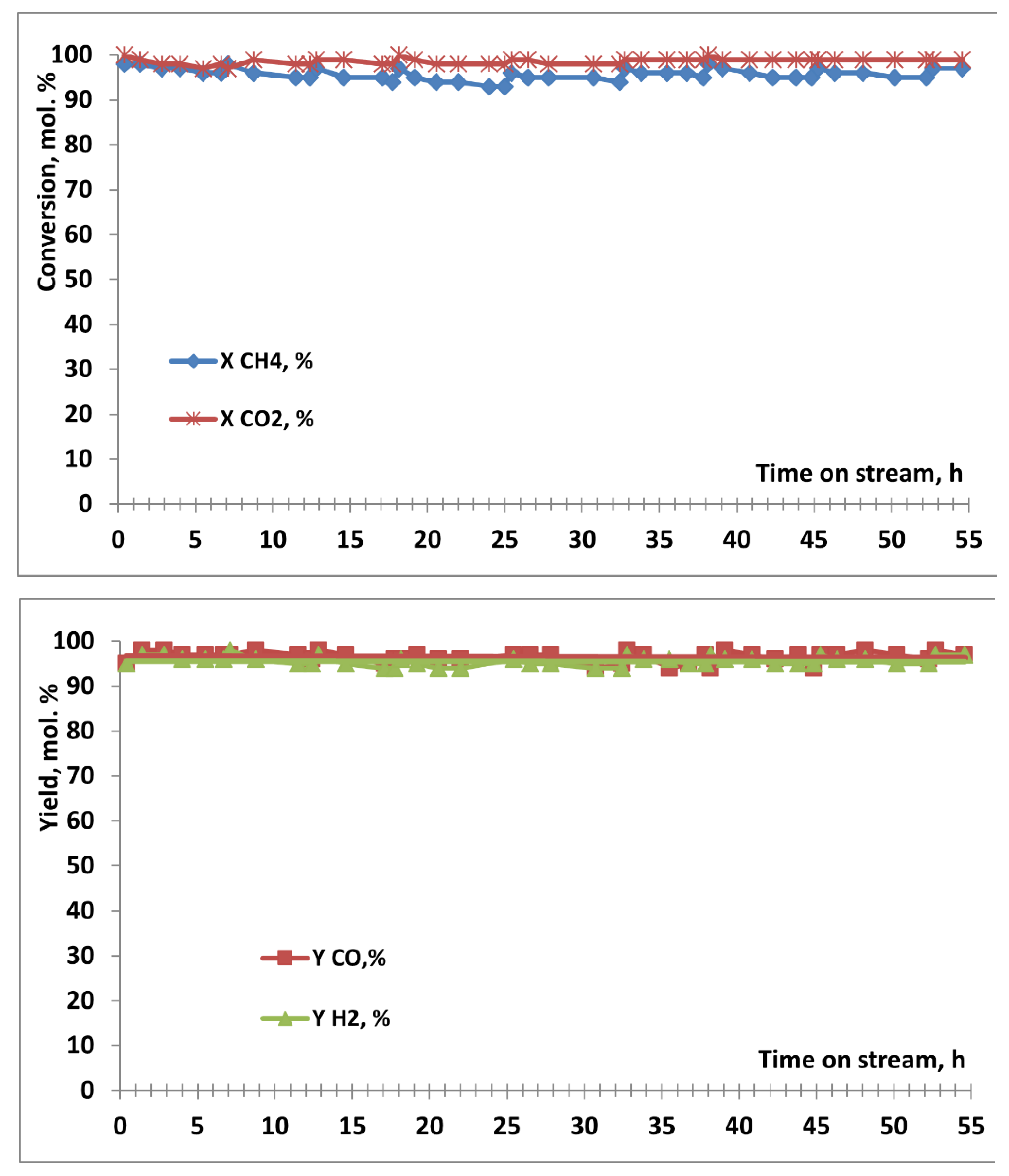
For comparison, we synthesized and tested a 23%Co/Sm2O3 material in the DRM reaction (Figure 7). The same material was previously tested in the DRM reaction after preheating in the reagent stream [35]. According to [35], at 900oC the formed catalyst shows a synthesis gas yield close to quantitative but contains 44.5 wt. % of carbon deposits. Taking into account the data from [35] and the tests of catalysts based on 2%Co/Sm2O3, 5%Co/Sm2O3, and 10%Co/Sm2O3, in the present work, this material was tested in the DRM reaction after preheating to 900oC for an hour in the high-purity nitrogen stream. Figure 7 demonstrates that for 55 h the catalyst formed from 23%Co/Sm2O3 retained 95-98% CH4 conversion, 98-100% CO2 conversion, 95-98% CO yield, and 94-97% H2 yield. At the same time, the data in Figure 7 confirm that, along with the DRM reaction (3), an insignificant reverse the water gas shift reaction (6) proceeds.
The catalysts formed during the DRM process and discharged from the reactor were investigated by XRD, TGA and TEM methods.
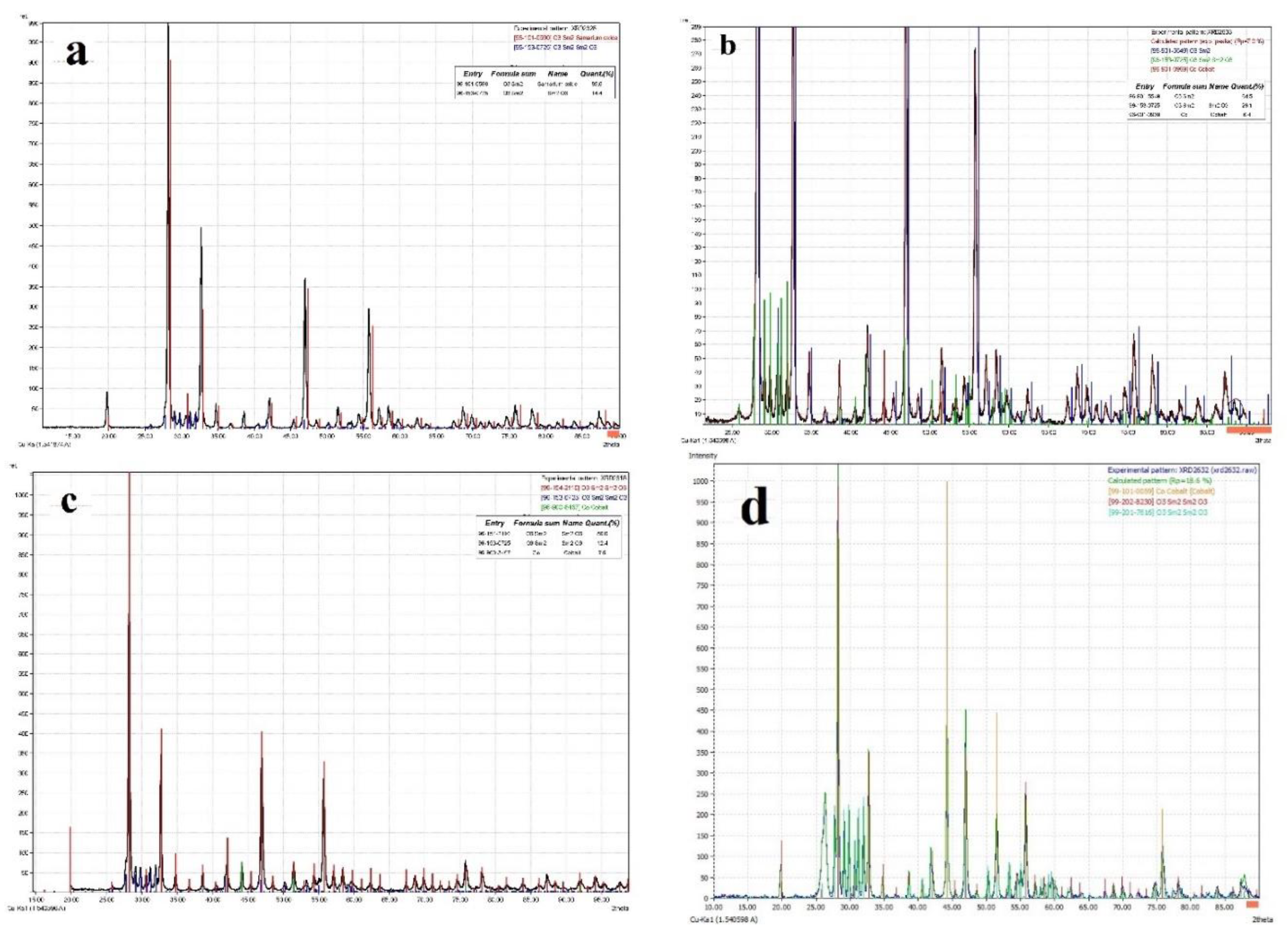
The XRD data of the spent catalysts are shown in Figure 8.
The XRD pattern of the spent catalyst derived from 2%Co/Sm2O3 (Figure 8a) shows only reflections due to cubic Sm2O3 (ICDD 96-101-0590) and rhombic Sm2O3 (ICDD 96-153-0725). The absence of reflections due to cobalt and its compounds may be explained by a small number of particles and their small size.
The XRD pattern of the spent catalyst derived from 5%Co/Sm2O3 (Figure 8b) exhibits, along with reflections due to cubic Sm2O3 (ICDD 96-901-5549) and rhombic Sm2O3 (ICDD 96-153-0725), reflections corresponding to metallic cobalt (ICDD 96-901-0969). In this case, the size of cobalt particles could not be correctly estimated according to the Debye-Scherrer formula.
The XRD pattern of the spent catalyst derived from 10%Co/Sm2O3 (Figure 8c) contains reflections due to cubic Sm2O3 (ICDD 96-154-2110), rhombic Sm2O3 (ICDD 96-153-0725), and metallic cobalt (ICDD 96-900-8467). In accordance with the Debye-Scherrer formula, the size of cobalt particles is 52 and 56 nm.
The XRD pattern of the spent catalyst derived from 23%Co/Sm2O3 (Figure 8d) shows reflections related to cubic Sm2O3 (ICDD 99-201-7616), rhombic Sm2O3 (ICDD 99-202-8230), and metallic cobalt (ICDD 99-101-0059). In accordance with the Debye-Scherrer formula, the size of cobalt particles is 43 and 48 nm.
Thus, the XRD data (Figure 8) indicate that the true DRM catalysts are Co/Sm2O3 composites of metallic cobalt dispersed in samarium oxide, which are derived from 2%Co/Sm2O3, 5%Co/Sm2O3, 10%Co/Sm2O3, and 23%Co/Sm2O3. It should be noted that all the formed composites maintain high activity in DRM for at least 50 h.
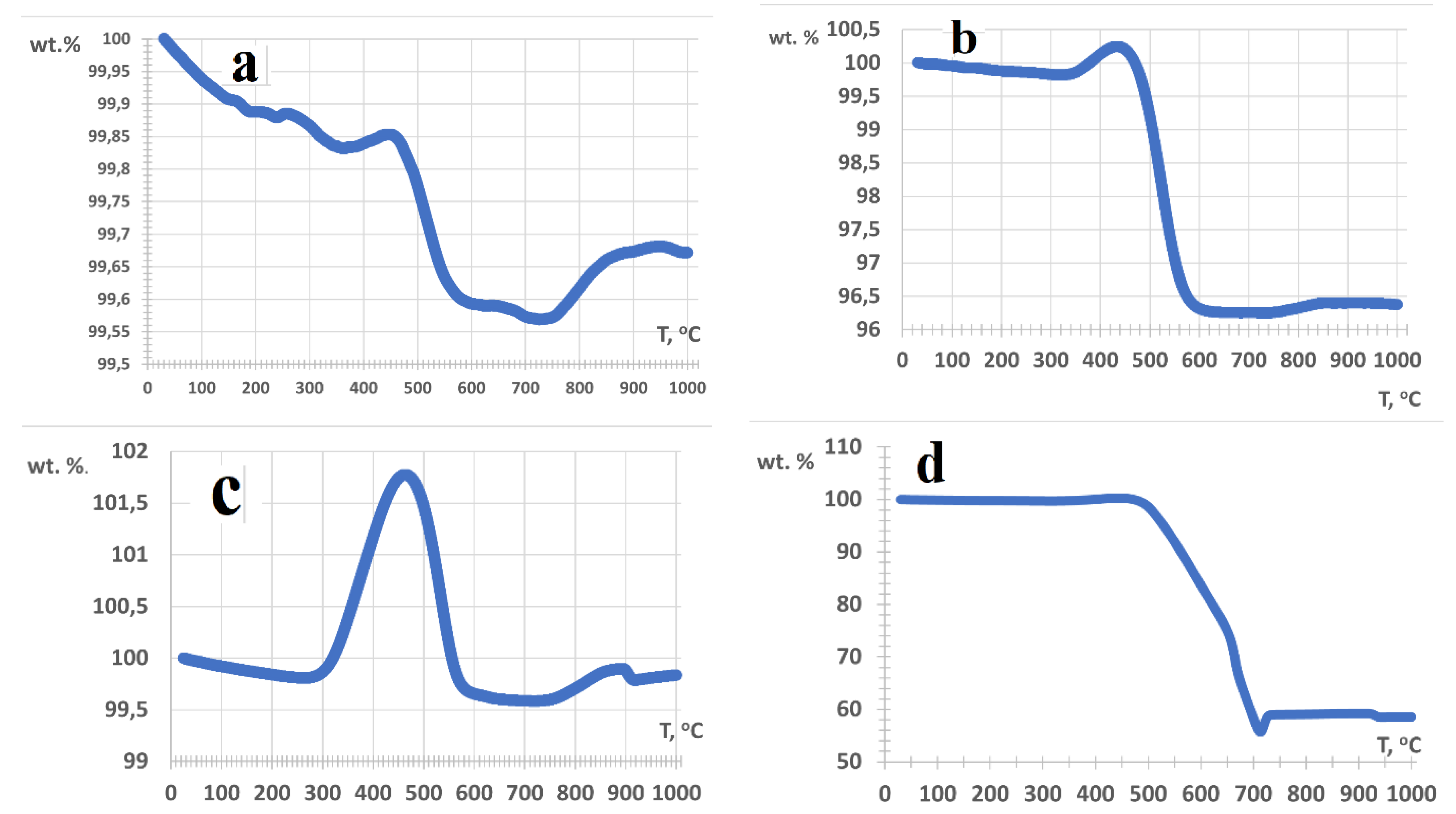
The TGA data obtained for the spent catalysts are shown in Figures 9a-d.
All the samples are characterized by a slight initial weight loss associated with the removal of adsorbed water and gases upon heating to 300oC. At higher temperatures, marked differences in TGA profiles are observed.
The TGA profile of the spent catalyst derived from 2%Co/Sm2O3 (Figure 9a) shows that upon heating from 350 to 450 oC, the weight slightly increases apparently due to the oxidation of metallic cobalt. At 450-650oC the weight decreases by 0.26%, which correlates with the combustion of carbonaceous deposits and the decomposition of carbonates. A slight weight loss at 650-750oC may be attributed to the combustion of carbon, and a subsequent increase in weight can be explained by the resynthesis of cobalt-samarium complex oxides.
The TGA profile of the spent catalyst derived from 5%Co/Sm2O3 (Figure 9b) indicates that upon heating from 320 to 440oC weight increases by 0.42% evidently due to the oxidation of metallic cobalt. At 440-730oC the weight decreases by 4%, in correlation with the combustion of carbonaceous deposits and the decomposition of carbonates. A slight weight loss at 650-750oC may also be associated with the combustion of carbon. A subsequent slight increase in weight is presumably caused by the resynthesis of cobalt-samarium complex oxides.
The TGA profile of the spent catalyst derived from 10%Co/Sm2O3 (Figure 9c) shows that upon heating from 260 to 460oC weight increases by 2%, which is apparently related to the oxidation of metallic cobalt. At 460-720oC the weight loss is 2.2%. This is apparently associated with the combustion of carbonaceous deposits and the decomposition of carbonates. Above 720oC, weight increases by 0.31% which is evidently due to the resynthesis of cobalt-samarium complex oxides.
The TGA data on the spent catalyst derived from 23%Co/Sm2O3, (Figure 9d) demonstrate that upon heating from 260 to 460oC an increase in weight is as low as 0.54%. This can apparently be explained by oxidation of metallic cobalt. At 460-620oC weight decreases by 20.72%. This is apparently due to the combustion of amorphous carbonaceous deposits and the decomposition of carbonates. Heating from 620 to 720oC resulted in a weight loss of 23.87% probably due to the combustion of graphite-like carbon. Above 720oC, there is a 3.5% increase in weight, which is apparently related to the resynthesis of cobalt-samarium complex oxides.
Thus, the TGA data of all the studied samples indicate the presence of metallic cobalt in the formed composites. The TGA data suggest that the catalyst formed from 2%Co/Sm2O3 is almost not subject to carburization. Catalysts based on 5%Co/Sm2O3 and 10%Co/Sm2O3 are carbonized to a small extent, whereas the catalyst based on 23%Co/Sm2O3 undergoes strong carbonization although it does not lose activity in DRM for more than 50 h.
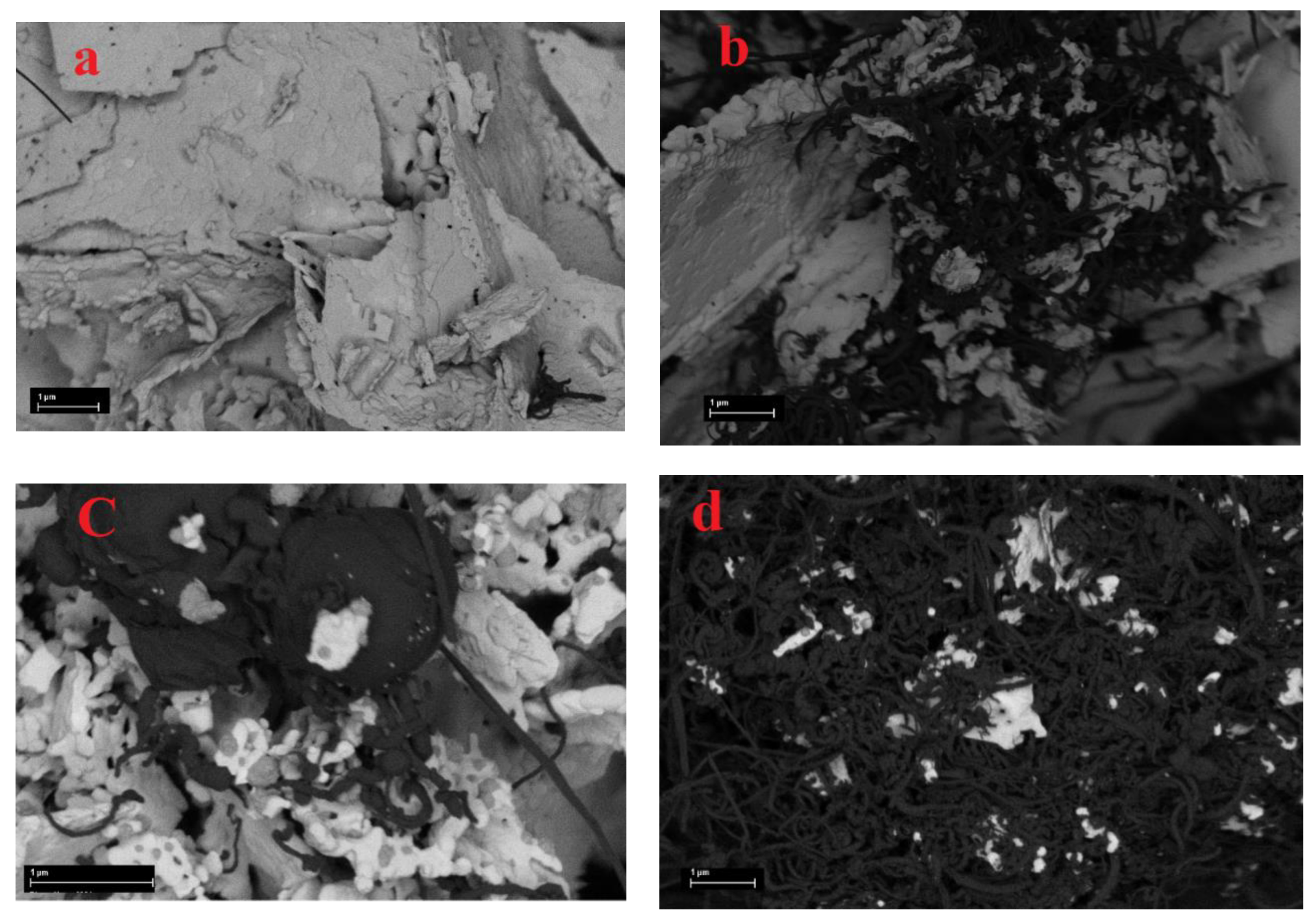
The TGA results are consistent with the SEM data (Figure 10 a-d).
The spent catalyst derived from 2%Co/Sm2O3 (Figure 10a) contains almost no carbon deposits. The spent catalysts based on 5%Co/Sm2O3 (Figure 10b) and 10%Co/Sm2O3 (Figure 10c), underwent noticeable carbonization, and the surface of the spent catalyst derived from 23%Co/Sm2O3 (Figure 10d) is almost completely covered with carbon deposits.
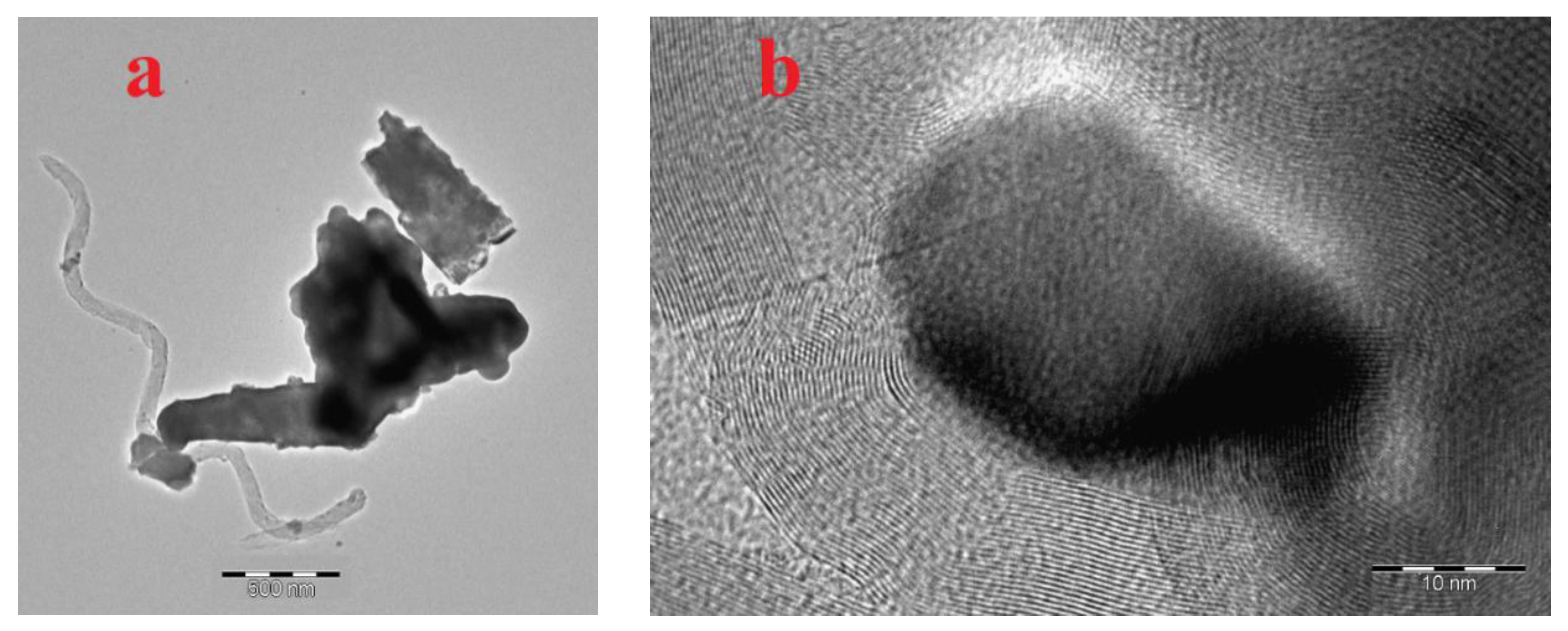
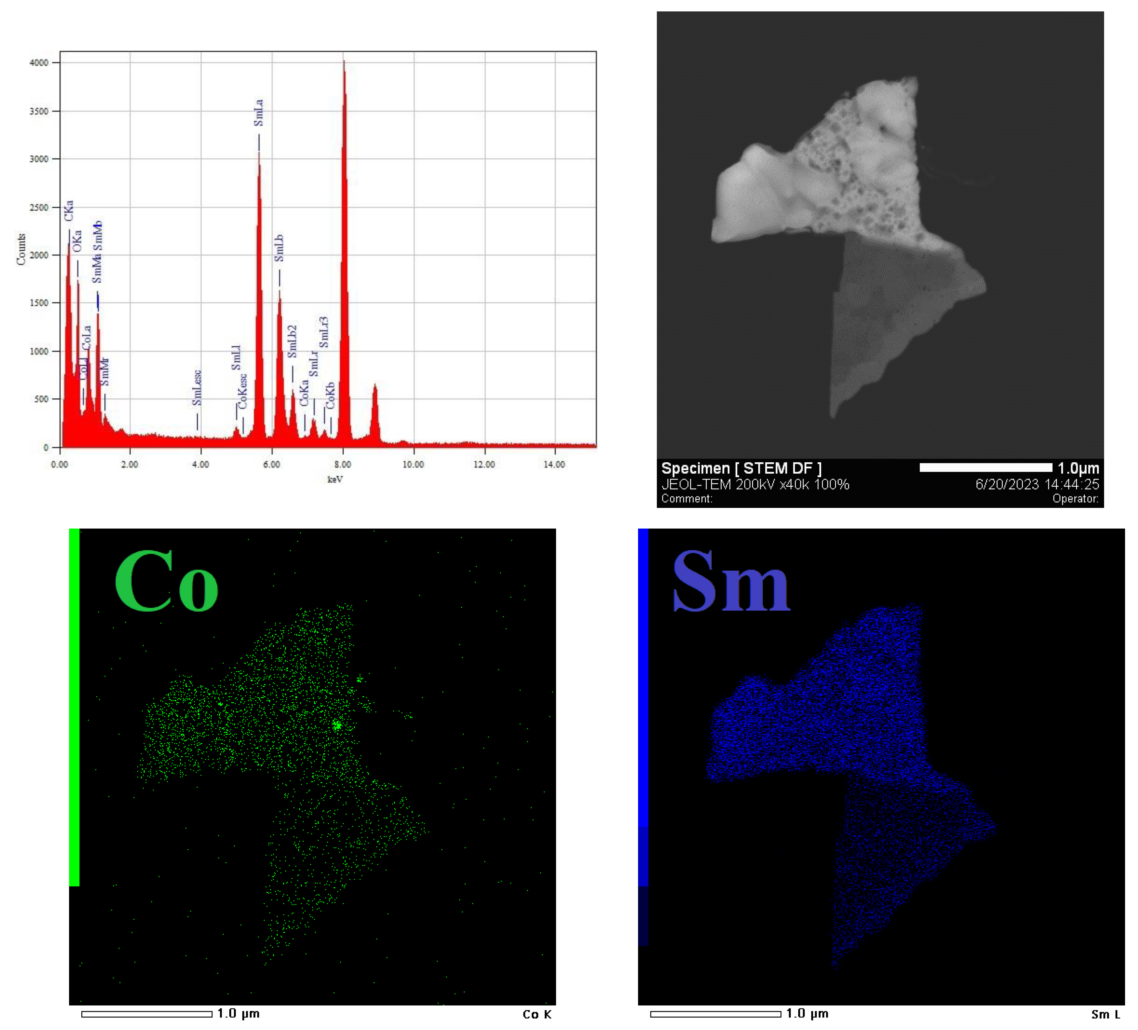
Spent catalysts with the lowest cobalt content, which were derived from 2%Co/Sm2O3 and 5%Co/Sm2O3, were additionally investigated by the TEM method. The TEM micrograph of the spent catalyst based on 2%Co/Sm2O3 (Figure 11a) demonstrates formation of an insignificant amount of carbon nanotubes. Figure 11b shows that the catalyst contains cobalt particles with a size of about 20 nm.
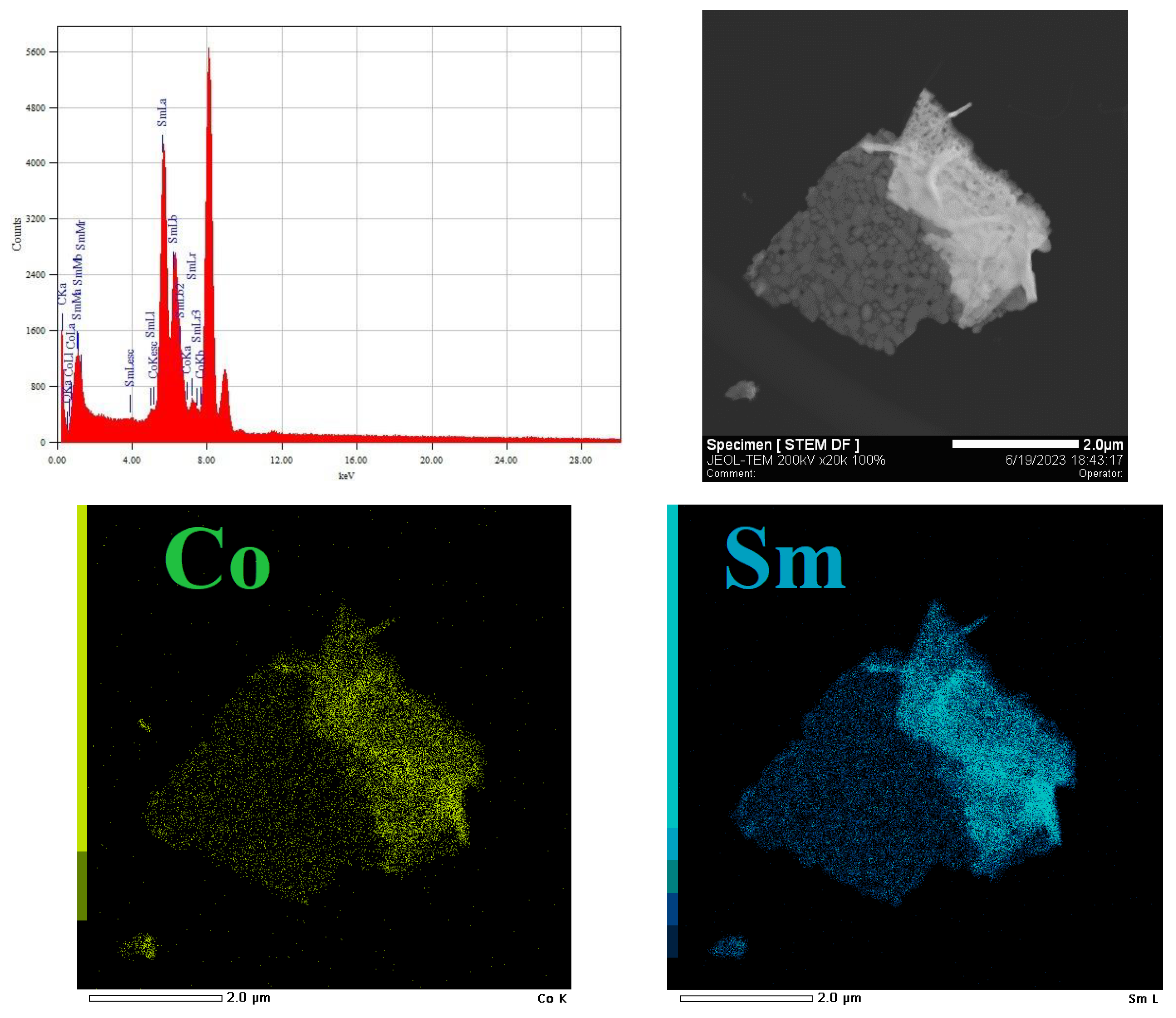
Figure 12 presents the TEM data on the elemental composition and distribution of cobalt and samarium in the spent catalyst derived from 2%Co/Sm2O3. It can be seen that cobalt atoms are evenly distributed in samarium oxide.
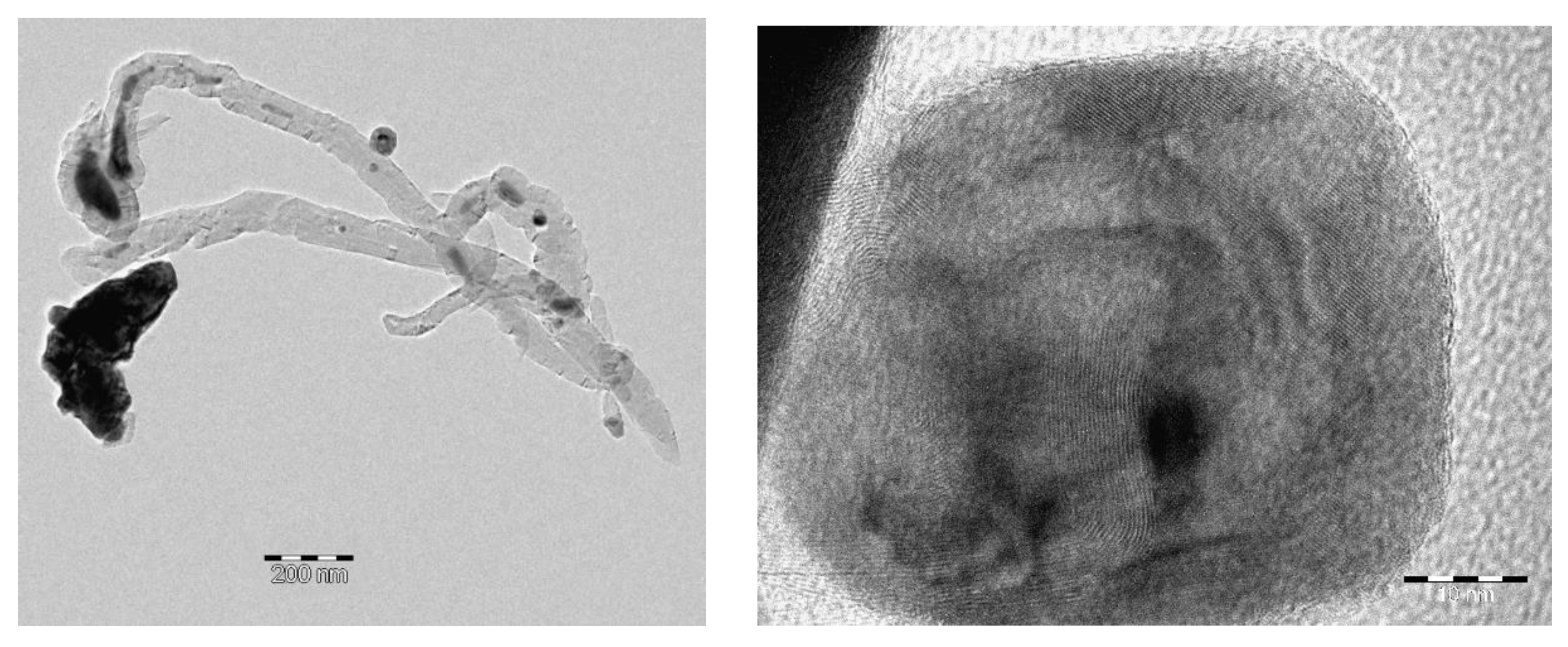
For comparison, the spent catalyst derived from 5%Co/Sm2O3, which is more prone to carbonization, was also investigated by TEM (Figure 13).
The TEM micrographs shows that the sample contains non-surface-bound carbon nanotubes and cobalt-containing particles up to 50 nm in size. A higher tendency of this sample to coking may be explained by an increase in the size of cobalt-containing particles.
The study of the elemental composition of this material (Figure 14) also showed that the distribution regions of cobalt and samarium atoms in the sample are coincident.
Thus, the simple method of synthesizing catalyst precursors, namely, evaporation of aqueous solutions of cobalt and samarium nitrates with subsequent calcination of the resulting material enables one to obtain materials that are precursors of selective and stable catalysts of the DRM reaction. This method is much simpler than most of the known methods used to prepare highly efficient and stable catalysts of this reaction on the basis of cobalt-samarium precursors [7,11,29,30,31], including single-phase perovskite SmCoO3 [29,30,31].
An effective way is developed to achieve high synthesis gas yields using the synthesized precatalysts which consists in heating samples in a nitrogen flow to an optimal temperature of 900oC. This DRM procure does not require catalyst pre-reduction by hydrogen or a CH4/CO2 mixture. The stable operation of the catalysts lasts for 50 h, and the yields of H2 and CO close to the thermodynamically predicted limits are achieved. The TGA and SEM data indicate that a high cobalt content in the precatalyst is not required to create a selective, stable, and carbonization resistant DRM catalyst. An increase in the cobalt content in the samples does not affect their stability for 50 h but significantly increases carbonization, which may hinder a longer stable operation of DRM catalysts.

4. Conclusions

The new simple method has been developed for the synthesis of materials that are effective precursors of catalysts for the production of hydrogen and carbon monoxide by the DRM reaction. It is shown that the amount of cobalt introduced into the precatalyst affects its phase composition. For example, according to XRD data, the 2%Co/Sm2O3 sample contains Sm2O3 and Sm2CoO4 phases. Materials based on 5%Co/Sm2O3 and 10%Co/Sm2O3 contain SmCoO3 along with Sm2O3. The 23%Co/Sm2O3 sample containing the same amount of cobalt as SmCoO3 perovskite consists of SmCoO3, Sm2O3, and Co3O4.
It has been demonstrated that the formation of efficient and stable DRM catalysts based on the synthesized materials does not require their pre-reduction with hydrogen or the initial mixture of reagents. The heating of the synthesized materials up to 900oC in a nitrogen flow and the subsequent supply of the equimolar CH4/CO2 mixture allow one to in situ obtain a selective and stable DRM catalyst operating for at least 50 h.
It has been shown that the cobalt content in the pre-catalyst significantly affects the carbonization resistance of the formed DRM catalyst. For example, the catalyst derived from 2%Co/Sm2O3 is not subject to carbonization when tested in DRM for 50 h. The catalysts based on 5%Co/Sm2O3 and 10%Co/Sm2O3 undergo noticeable carbonization, which, however, does not worsen the results of DRM for 50 h. The 23%Co/Sm2O3 derived catalyst containing the same amount of cobalt as perovskite SmCoO3 maintains stability in the DRM reaction for 50 h but forms a significant amount of carbon, which likely affects its stability during long-term operation. This implies that a cobalt content of 2 wt. % is optimal for obtaining the stable cobalt-samarium DRM catalyst, provided its preheating to 900oC in a nitrogen flow followed by the supply of reagents. The stability of this catalyst is associated with the formation of sintering-resistant cobalt metal particles with a size of about 20 nm. Similar observations were made in the study of DRM using supported nickel and nickel-cobalt catalysts containing these metals in an amount of no more than 2 wt. % [5,40].
In general, the catalyst formed from the 2%Co/Sm2O3 material is promising for practical use, since it is almost not subject to carbonization and sintering of cobalt particles and demonstrates consistently high yields of H2 and CO. Its application in the DRM reaction makes it possible to efficiently utilize two greenhouse gases, methane and carbon dioxide, which is of great ecological importance. In addition, it can potentially be used to produce "green" hydrogen by the conversion of renewable raw material--biogas.

6. Patents

Russian Patent Application RU 2023 113 594 A (25.05.2023).

Author Contributions

Conceptualization, A.G.D. and A.S.L.; methodology, A.G.D. and A.S.L.; investigation, A.S.L, V.A.A., A.A.S., K.A.C. and G.A.S.; data curation, A.S.L., V.A.A. and M.A.B.; writing—original draft preparation, A.S.L.; writing—review and editing, A.S.L. and A.G.D.; supervision, A.G.D. and A.S.L.C.; funding acquisition, A.G.D. All authors have read and agreed to the published version of the manuscript.

Funding

This research was funded by Russian Science Foundation, grant number 23-13-00098. TGA, H2-TPR and SEM experiments were carried out within the state funding of TIPS RAS. SEM images were obtained at the IGIC RAS Joint Research Center for Physical Methods of Research.

Data Availability Statement

Russian Science Foundation, https://rscf.ru/project/

Conflicts of Interest

The authors declare no conflict of interest.

References

  1. Jang, W.-J.; Shim, J.-O.; Kim, H.-M.; Yoo, S.-Y.; Roh, H.-S. A review on dry reforming of methane in aspect of catalytic properties. Catal. Today 2019, 324, 15–26. [Google Scholar] [CrossRef]
  2. Su, B.; Wang, Y.; Xu, Z.; Han, W.; Jin, H.; Wang, H. Novel ways for hydrogen production based on methane steam and dry reforming integrated with carbon capture. Energy Conversion and Management 2022, 270, 116199. [Google Scholar] [CrossRef]
  3. Singh, R.; Dhir, A.; Mohapatra, S.K.; Mahla, S.K. Dry reforming of methane using various catalysts in the process: review. Biomass Conv. Bioref. 2020, 10, 567–587. [Google Scholar] [CrossRef]
  4. Holmen, A. Direct Conversion of Methane to Fuels and Chemicals. Catal. Today 2009, 142, 2–8. [Google Scholar] [CrossRef]
  5. Moiseev, I.I.; Loktev, A.S.; Shlyakhtin, O.A.; Mazo, G.N.; Dedov, A.G. New approaches to the design of nickel, cobalt, and nickel–cobalt catalysts for partial oxidation and dry reforming of methane to synthesis gas. Petrol. Chem. 2019, 59 Suppl. 1, S1–S27. [Google Scholar] [CrossRef]
  6. Chen, L.; Qi, Z.; Zhang, S.; Su, J.; Somorjai, G.A. Catalytic Hydrogen Production from Methane: A Review on Recent Progress and Prospect. Catalysts 2020, 10, 858–876. [Google Scholar] [CrossRef]
  7. Elbadawi, A.H.; Ge, L.; Li, Z.; Liu, S.; Wang, S.; Zhu, Z. Catalytic partial oxidation of methane to syngas: review of perovskite catalysts and membrane reactors. Catal. Rev. 2021, 63, 1–67. [Google Scholar] [CrossRef]
  8. Al-Sayari, S.A. Recent Developments in the Partial Oxidation of Methane to Syngas. Open Catalysis J. 2013, 6, 17–28. [Google Scholar] [CrossRef]
  9. Alhassan, M.; Jalil, A.A.; Nabgan, W.; Hamid, M.Y.S.; Bahari, M.B.; Ikram, M. Bibliometric studies and impediments to valorization of dry reforming of methane for hydrogen pro-duction. Fuel 2022, 328, 125240. [Google Scholar] [CrossRef]
  10. Kumar, R.; Kumar, A.; Pal, A. Overview of hydrogen production from biogas reforming: Technological advancement. Intern. J. Hydrogen Energy 2022, 47, 34831–34855. [Google Scholar] [CrossRef]
  11. Bhattar, S.; Abedin, Md.A.; Kanitkar, S.; Spivey, J.J. A review on dry reforming of methane over perovskite derived catalysts. Catal. Today 2021, 365, 2–23. [Google Scholar] [CrossRef]
  12. The, L.P.; Setiabudi, H.D.; Timmiati, S.N.; Aziz, M.A.A.; Annuar, N.H.R.; Ruslan, N.N. Recent progress in ceria-based catalysts for the dry reforming of methane: A review. Chem. Engineering Sci. 2021, 242, 116606. [Google Scholar] [CrossRef]
  13. Yentekakis, I.V.; Panagiotopoulou, P.; Artemakis, G. A review of recent efforts to promote dry reforming of methane (DRM) to syngas production via bimetallic catalyst formulations. Appl. Catal. B: Environmental 2021, 296, 120210. [Google Scholar] [CrossRef]
  14. Wang, C.; Wang, Y.; Chen, M.; Liang, D.; Yang, Z.; Cheng, W.; Tang, Z.; Wang, J.; Zhang, H. Recent advances during CH4 dry reforming for syngas production: A mini review. Intern. J. of Hydrogen Energy, 2021, 46, 5852–5874. [Google Scholar] [CrossRef]
  15. le Saché, E.; Reina, T.R. Analysis of dry reforming as direct route for gas phase CO2 conversion. The past, the present and future of catalytic DRM technologies. Progr. in Energy and Combustion Sci. 2022, 89, 100970. [Google Scholar] [CrossRef]
  16. Hambali, H.U.; Jalil, A.A.; Abdulrasheed, A.A.; Siang, T.J.; Gambo, Y.; Umar, A.A. Zeolite and clay based catalysts for CO2 reforming of methane to syngas: A review. Intern. J. of Hydrogen Energy 2022, 47, 30759–30787. [Google Scholar] [CrossRef]
  17. Baharudin, L.; Rahmat, N.; Othman, N.H.; Shah, N.; Syed-Hassan, S.S.A. Formation, control, and elimination of carbon on Ni-based catalyst during CO2 and CH4 conversion via dry reforming process: A review. J. of CO2 Utilization 2022, 61, 102050. [Google Scholar] [CrossRef]
  18. Mortensen, P.M.; Dybkjær, I. Industrial scale experience on steam reforming of CO2-rich gas. Appl. Catal. A: General 2015, 495, 141–151. [Google Scholar] [CrossRef]
  19. Teuner, S.C.; Neumann, P.; Von Linde, F. The Calcor standard and Calcor economy processes. OIL GAS European Magazine 2001, № 3, 44–46. https://www.caloric.com/wp-content/uploads/2016/11/Caloric-Downloads-Calcor.pdf.
  20. Usman, M.; Wan Daud, W.M.A.; Abbas, H.F. Dry reforming of methane: Influence of process parameters. A review. Renewable and Sustainable Energy Rev. 2015, 45, 710–744. [Google Scholar] [CrossRef]
  21. Schulz, L.A.; Kahle, L.C.S.; Delgado, K.H.; Schunk, S.A.; Jentys, A.; Deutschmann, O.; Lercher, J.A. On the coke deposition in dry reforming of methane at elevated pressures. Appl. Catal. A: General 2015, 504, 599–607. [Google Scholar] [CrossRef]
  22. Jang, W.-J.; Jeong, D.-W.; Shim, J.-O.; Kim, H.-M.; Roh, H.-S.; Son, I.H.; Lee, S.J. Combined steam and carbon dioxide reforming of methane and side reactions: Thermodynamic equilibrium analysis and experimental application. Appl. Energy 2016, 173, 80–91. [Google Scholar] [CrossRef]
  23. Yusuf, M.; Farooqi, A.S.; Keong, L.K.; Hellgardt, K.; Abdullah, B. Contemporary trends in composite Ni-based catalysts for CO2 reforming of methane. Chem. Engineering Science 2021, 229, 116072. [Google Scholar] [CrossRef]
  24. Jafarbegloo, M.; Tarlani, A.; Wahid Mesbah, A.; Sahebdelfar, S. Thermodynamic analysis of carbon dioxide reforming of methane and its practical relevance. Intern. J. of Hydrogen Energy 2015, 40, 2445–2451. [Google Scholar] [CrossRef]
  25. Khoshtinat Nikoo, M.; Amin, N.A.S. Thermodynamic analysis of carbon dioxide reforming of methane in view of solid carbon formation. Fuel Process. Technol. 2011, 92, 678–691. [Google Scholar] [CrossRef]
  26. Aziz, M.A.A.; Setiabudi, H.D.; Teh, L.P.; Annuar, N.H.R.; Jalil, A.A. A review of heterogeneous catalysts for syngas production via dry reforming. J. of the Taiwan Institute of Chem. Engineers 2019, 101, 139–158. [Google Scholar] [CrossRef]
  27. Choudhary, V.R.; Mondal, K.C.; Mamman, A.S.; Joshi, U.A. Carbon-free dry reforming of methane to syngas over NdCoO3 perovskite-type mixed metal oxide catalyst. Catal. Lett. 2005, 100, 271–276. [Google Scholar] [CrossRef]
  28. Royer, S.; Duprez, D.; Can, F.; Courtois, X.; Batiot-Dupeyrat, C.; Laassiri, S.; Alamdari, H. Perovskites as Substitutes of Noble Metals for Heterogeneous Catalysis: Dream or Reality. Chem. Rev. 2014, 114, 10292–10368. [Google Scholar] [CrossRef]
  29. Gavrikov, A.V.; Loktev, A.S.; Ilyukhin, A.B.; Mukhin, I.E.; Bykov, M.A.; Maslakov, K.I.; Vorobei, A.M.; Parenago, O.O.; Sadovnikov, A.A.; Dedov, A.G. Supercritical Fluid Assisted Modification combined with the Resynthesis of SmCoO3 as Effective Tool to Enhance Long-term Performance of SmCoO3-derived Catalysts for Dry Reforming of Methane to Syngas. Dalton Trans. 2022, 51, 18446–18461. [Google Scholar] [CrossRef] [PubMed]
  30. Gavrikov, A.V.; Ilyukhin, A.B.; Belova, E.V.; Yapryntsev, A.D.; Dobrokhotova, Z.V.; Khrushcheva, A.V.; Efimov, N.N. Rapid preparation of SmCoO3 perovskite via uncommon though efficient precursors: Composition matters! Ceram. Int. 2020, 46, 13014–13024. [Google Scholar] [CrossRef]
  31. Osazuwa, O.U.; Cheng, C.K. Catalytic conversion of methane and carbon dioxide (greenhouse gases. into syngas over samarium-cobalt-trioxides perovskite catalyst. J. of Cleaner Production 2017, 148, 202–211. [Google Scholar] [CrossRef]
  32. Salaev, M.A.; Liotta, L.F.; Vodyankina, O.V. Lanthanoid-containing Ni-based catalysts for dry reforming of methane: A review. Int. J. of Hydrogen Energy 2022, 47, 4489–4535. [Google Scholar] [CrossRef]
  33. de Lira Lima, D.C.; Lemos, I.P.; Gomes, Rodrigues, R.S.; L.M.T.S.; Fréty, R.T.; Resini, C.; Junior, R.B.S.; Brandão, S.T. Study of LaNi1-xCoxO3 Perovskites-Type Oxides Either Pure or Mixed with SiO2 as Catalytic Precursors Applied in CH4 Dry-Reforming. Catal Lett. 2023, 153, 2137–2148. Catal Lett. [CrossRef]
  34. Dedov, A.G.; Loktev, A.S.; Ivanov, V.K.; Bykov, M.A.; Mukhin, I.E.; Lidzhiev, M.M.; Rogaleva, E.V.; Moiseev, I.I. Selective oxidation of methane to synthesis gas: Cobalt- and nickel-based catalysts. Doklady Phys. Chemistry 2015, 461, 73–79. [Google Scholar] [CrossRef]
  35. Loktev, A.S.; Mukhin, I.E.; Bykov, M.A.; Sadovnikov, A.A.; Osipov, A.K.; Dedov, A.G. Novel high-performance catalysts for partial oxidation and dry reforming of methane to synthesis gas. Petrol. Chemistry 2022, 62, 526–543. [Google Scholar] [CrossRef]
  36. Loktev, A.S.; Arkhipova, V.A.; Bykov, M.A.; Sadovnikov, A.A.; Dedov, A.G. Cobalt–Samarium Oxide Composite as a Novel High-Performance Catalyst for Partial Oxidation and Dry Reforming of Methane into Synthesis Gas. Petrol. Chemistry 2023. Open access publication. [Google Scholar] [CrossRef]
  37. Rietveld, H.M. A profile refinement method for nuclear and magnetic structures. J. of Appl. Crystallography 1969, 2, 65–71. [Google Scholar] [CrossRef]
  38. Olusola, J.O.; Sudip, M. Temperature programme reduction (TPR) studies of cobalt phases in γ-alumina supported cobalt catalysts. J. of Petrol. Technol. and Alternative Fuels 2016, 7, 1–12. [Google Scholar] [CrossRef]
  39. Ma, F.; Chen, Y.; Lou, H. Characterization of perovskite-type oxide catalysts RECoO3 by TPR. React. Kinet. Catal. Lett. 1986, 31, 47–53. [Google Scholar]
  40. Dedov, A.G.; Loktev, A.S.; Mukhin, I.E.; Baranchikov, A.E.; Ivanov, V.K.; Bykov, M.A.; Solodova, E.V.; Moiseev, I.I. Effect of the Support Nature on Stability of Nickel and Nickel–Cobalt Catalysts for Partial Oxidation and Dry Reforming of Methane to Synthesis Gas. Petrol. Chemistry 2019, 59, 385–393. [Google Scholar] [CrossRef]
Figure 1. XRD patterns of (a) 2%Co/Sm2O3, (b) 5%Co/Sm2O3, (c) 10%Co/Sm2O3, and (d) 23%Co/Sm2O3.
Preprints 78514 g001
Figure 2. SEM images of (a) 2%Co/Sm2O3, (b) 5%Co/Sm2O3, (c) 10%Co/Sm2O3, and (d) 23%Co/Sm2O3.
Preprints 78514 g002
Figure 3. H2-TPR profiles of (a) 2%Co/Sm2O3, (b) 5%Co/Sm2O3, (c) 10%Co/Sm2O3, and (d) 23%Co/Sm2O3.
Preprints 78514 g003
Figure 4. The performance in DRM process on 2%Co/Sm2O3 derived catalyst preheated to 900oC in N2 flow.
Preprints 78514 g004
Figure 5. Performance of 5%Co/Sm2O3 derived catalyst preheated to 900oC in N2 flow in DRM process.
Preprints 78514 g005
Figure 6. Performance of 10%Co/Sm2O3 derived catalyst preheated to 900oC in N2 flow in DRM.
Preprints 78514 g006
Figure 7. Performance of 23%Co/Sm2O3 derived catalyst preheated to 900oC in N2 flow in DRM process.
Preprints 78514 g007
Figure 8. XRD patterns of spent catalysts derived from (a) 2%Co/Sm2O3, (b) 5%Co/Sm2O3, (c) 10%Co/Sm2O3 , and (d) 23%Co/Sm2O3.
Preprints 78514 g008
Figure 9. TGA profiles of the spent catalysts derived from (a) 2%Co/Sm2O3, (b) 5%Co/Sm2O3, (c) 10%Co/Sm2O3, and (d) 23%Co/Sm2O3.
Preprints 78514 g009
Figure 10. ESB SEM images of spent catalysts derived from (a) 2%Co/Sm2O3, (b) 5%Co/Sm2O3, (c) 10%Co/Sm2O3 (c), and (d) 23%Co/Sm2O3.
Preprints 78514 g010
Figure 11. TEM images of spent catalyst derived from 2%Co/Sm2O3.
Preprints 78514 g011
Figure 12. TEM images for the spent catalyst derived from 2%Co/Sm2O3: overall elemental spectra, STEM DF image; Co and Sm elemental maps.
Preprints 78514 g012
Figure 13. TEM images of spent catalyst derived from 5%Co/Sm2O3.
Preprints 78514 g013
Figure 14. TEM images for the spent catalyst derived from 5%Co/Sm2O3: overall elemental spectra, STEM DF image; Co and Sm elemental maps.
Preprints 78514 g014
Table 1. The code of catalysts, the mass of reagents taken for the synthesis of catalysts and the specific surface area (SBET) of the materials obtained.
Code of catalysts Mass of Сo(NO3)2•6H2O, g Mass of Sm(NO3)3•6H2O, g SBET, m2/g
2%Co/Sm2O3 0.49 12.49 1.79
5%Co/Sm2O3 1.23 12.11 2.82
10%Co/Sm2O3 2.47 11.47 3.45
23%Co/Sm2O3 2.91 4.47 3.82
Disclaimer/Publisher’s Note: The statements, opinions and data contained in all publications are solely those of the individual author(s) and contributor(s) and not of MDPI and/or the editor(s). MDPI and/or the editor(s) disclaim responsibility for any injury to people or property resulting from any ideas, methods, instructions or products referred to in the content.
Copyright: This open access article is published under a Creative Commons CC BY 4.0 license, which permit the free download, distribution, and reuse, provided that the author and preprint are cited in any reuse.
Prerpints.org logo

Preprints.org is a free preprint server supported by MDPI in Basel, Switzerland.

Subscribe

© 2024 MDPI (Basel, Switzerland) unless otherwise stated