1. Introduction
A subgrade is an important part of a road structure. One of the most common problems associated with subgrade use is settlement, which affects the stability and original strength of the subgrade and thereby, the strength and stability of the pavement, completely destroys the subgrade structure, and reduces driving safety and comfort. Unfavorable physical characteristics of the underlying soil layer and external load conditions make many special soil subgrades prone to large-scale continuous settlement and deformation, resulting in excessive long-term settlement after the completion of the embankment[
1,
2]. Temperature changes cause lateral uneven settlement of permafrost subgrades[
3]. Long-term monitoring of subgrade settlement and related early warning strategies play a crucial role in preventing and controlling major disasters.
Conventional monitoring technologies for subgrade settlement, such as inclinometers, extensometers, total stations, global positioning systems, and static leveling systems have been in used for a long time and are generally classified as "traditional point-based monitoring technologies"[
4]. Emerging monitoring technologies include interferometric synthetic aperture radar (INSAR), digital image correlation (DIC), and terrestrial laser scanning (TLS). For wide-area monitoring, INSAR [
5,
6], TLS [
7], and DIC [
8] can achieve high-precision measurement over a wide range, reaching centimeter-level or even higher precision. However, these technologies are mainly used to measure the displacement of the outer surface of a subgrade or pavement structure. INSAR monitoring is limited by weather and blocked objects, such that ultra-high-resolution data is rarely obtained. TLS and DIC measurements have the advantages of a wide range, high precision, and a high acquisition speed but continuous long-term uninterrupted observation is difficult to realize. The aforementioned traditional point-based monitoring techniques or quasidistributed fiber Bragg grating can monitor dense internal deformation of a subgrade. However, a limited number of subgrade monitoring sections can be selected in advance and monitoring blind spots are inevitable. Increasing the number of sensors results in a sharp increase in the complexity and cost of the system, which is not feasible for long-distance and large-scale monitoring[
9]. The aforementioned problems have affected the ability to identify disaster risks in road engineering. Therefore, the development of automated technology for the real-time monitoring of distributed internal deformation in a subgrade would constitute a substantial advancement in the study of the early induction process and evolution mechanism of large-scale uneven settlement in a subgrade.
Distributed optical fiber sensors (DOFS) is such an alternative monitoring technology[
10]. This novel monitoring technology has been developed over the last 20 years. Compared with electromechanical measurement, optical-fiber sensing has the advantages of being safe, explosion-proof, resistant to corrosion and high temperatures, small, lightweight, flexible, and convenient to use as well as being able to prevent electromagnetic interference and realize remote signal transmission and measurement control. Since the first report on using Brillouin scattering in optical fibers to measure distributed temperature and strain[
11], various distributed optical-fiber monitoring technologies have been developed, such as the optical time-domain reflectometer(OTDR), Brillouin optical time-domain reflectometer (BOTDR), and optical frequency-domain reflectometer, resulting in considerable improvements of the sensing range and spatial resolution[
12].
Brillouin optical time-domain analysis (BOTDA) can achieve a spatial resolution of 2 cm using a 2-km sensing optical fiber and has a sensing range of up to 120 km[
13,
14]. This technology has been successfully applied in large-scale civil and structural engineering. The long sensing range of DOFS has been fully exploited for bridge-structure monitoring[
15,
16,
17], the high spatial resolution of DOFS has been utilized for pile-foundation monitoring[
18,
19,
20,
21], and DOFS has been applied to pavement structure with satisfactory results[
22,
23]. In addition to structural engineering, DOFS is widely used in geotechnical engineering. For slope and mining engineering, the optical fiber is usually directly buried to ensure minimal deformation in the soil and facilitate early disaster warning[
24,
25,
26]. Direct burial installation is also adopted for monitoring large ground deformation[
27,
28,
29], where optical fibers are attached to pipes, anchors, and other structures, and the strain measured in the optical fiber is converted to a displacement deformation commonly used in engineering[
30,
31,
32]. Although DOFS has been widely used in geotechnical engineering monitoring, ensuring deformation coupling between an optical fiber or affiliated structures with soil constitutes a technical bottleneck. Excessively large soil deformations may result in slippage between the optical fiber and soil[
33,
34]. That is, DOFS is suitable for measuring small deformations[
35,
36].
A distributed, low-cost, and reliable method for monitoring settlement is needed to evaluate the safety of a subgrade or foundation. Therefore, ensuring coupling between an optical fiber and soil to realize continuous monitoring of internal settlement is very important. A novel monitoring method based on an optical-fiber-embedded beam (OFEB) was developed in this study. First, a testing mechanism was proposed and a measurement method using the OFEB was developed. Then, a simple calibration test and a test on a similarity model were carried out to evaluate the OFEB performance. Finally, numerical modeling was used to optimize the material and size parameters of the OFEB and a method to improve the coupling between the OFEB and soil was developed to increase the OFEB measurement range. Experimental results show that the OFEB is suitable for monitoring distributed internal settlement and that the monitoring accuracy is acceptable before large slip between the subgrade soil and the OFEB occurs.
2. Action mechanism and calibration of the optical-fiber-embedded beam (OFEB)
2.1. Test principle
A single-mode optical fiber was symmetrically embedded on the upper and lower surfaces of a flexible pipe to construct the OFEB. When the OFEB deforms with the subgrade soil, the vertical displacement of the subgrade manifests as a deflection of the OFEB. The axial strain measured by the optical fiber is integrated to calculated the vertical deflection of the beam. The calculation is based on bending deformation theory for a beam.
Figure 1 is a schematic of the deflection of the beam, which is expressed as
ω = f(x). Assuming plane and small deformation of the beam section and considering the mechanical conditions under which deformation occurs and the definition of the curvature of the beam section, the curvature at any point in the beam can be expressed as follows:
where at any point of the beam,
ρ is the radius of curvature;
εa and
εb are the upper and lower surface strains, respectively;
θ is the tangent angle; and
s is arc length.
Formula (1) can be used to deduce
According to the boundary conditions on the beam shown in
Figure 1,
Thus,
The beam deflection can be calculated as follows:
As the optical fibers embedded on the upper and lower surfaces of the beam are symmetrically arranged, the Brillouin frequency shift induced by a change in the temperature is approximately the same at any point on these surfaces. Thus, the Brillouin frequency shifts induced by a temperature change cancel each other and it is not necessary to perform temperature compensation for the OFEB.
2.2. Calibration test
The accuracy of settlement measurement is very important. Thus, a calibration test was carried to assess the measurement accuracy of the OFEB.
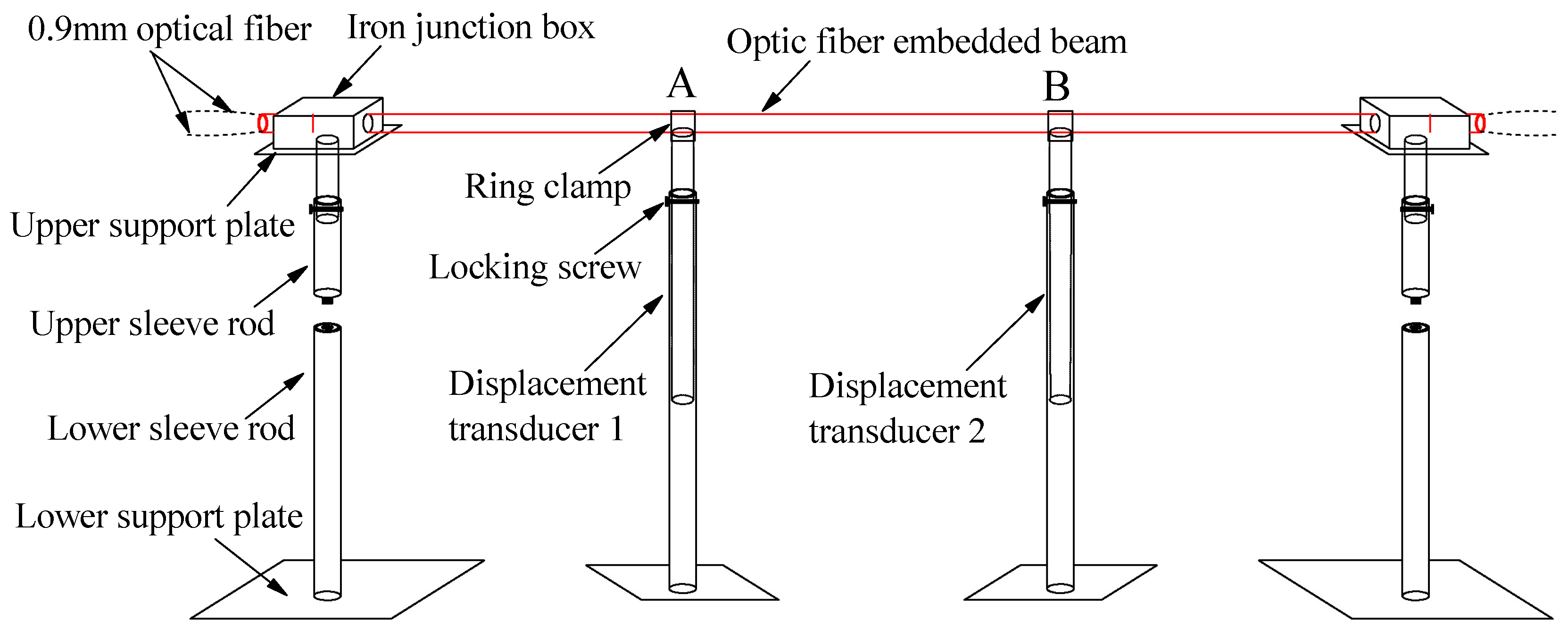
As shown in
Figure 2, the ends of the OFEB ends are consolidated on movable supports with an adjustable height to facilitate on-site installation. A displacement transducer is used to measure the beam deflection to calibrate the measurements of the optical fiber. A 0.9-mm-diameter single-mode tight-jacketed optical fiber is used as the sensor, and the beam body is a uniform and flexible high density polyethylene (HDPE) pipe with an external diameter
D of 25 mm and a thickness of 2.5 mm.
First, the OFEB was constructed: an optical fiber was laid symmetrically along the upper and lower surfaces of the HDPE pipe, coated with epoxy resin glue, and firmly bonded to the pipe. A 2.2-m length of the OFEB was used to perform a calibration test. An excessively long OFEB was not constructed to enable the calibration test to be carried out in the laboratory. Second, the OFEB was fixed on the support by being passed through an iron junction box filled with epoxy resin glue. The consolidation length at the end of the beam was removed to obtain an OFEB with an effective test length of 2 m for the calibration test.
A customized displacement transducer with a measurement range of 400 mm and a measurement accuracy of 0.1 mm was used in this study. Displacement transducers were arranged at 1/3rd and 2/3rds of the length of the OFEB (corresponding to the measurement points A and B shown in
Figure 2, respectively). The top ends of the displacement transducers were connected to the OFEB through a ring clamp, and a locking screw was used to control the settling rod to drive the OFEB to realize differential settlement. During the test, no settlement occurred at A, but random settlement deformation occurred at B. Five groups of calibration tests on differential settlement (Test 1–Test 5) were conducted.
2.3. Test results
Formula (4) was used to convert the Brillouin frequency shift measured in the five calibration tests to the change in the displacement at different positions.
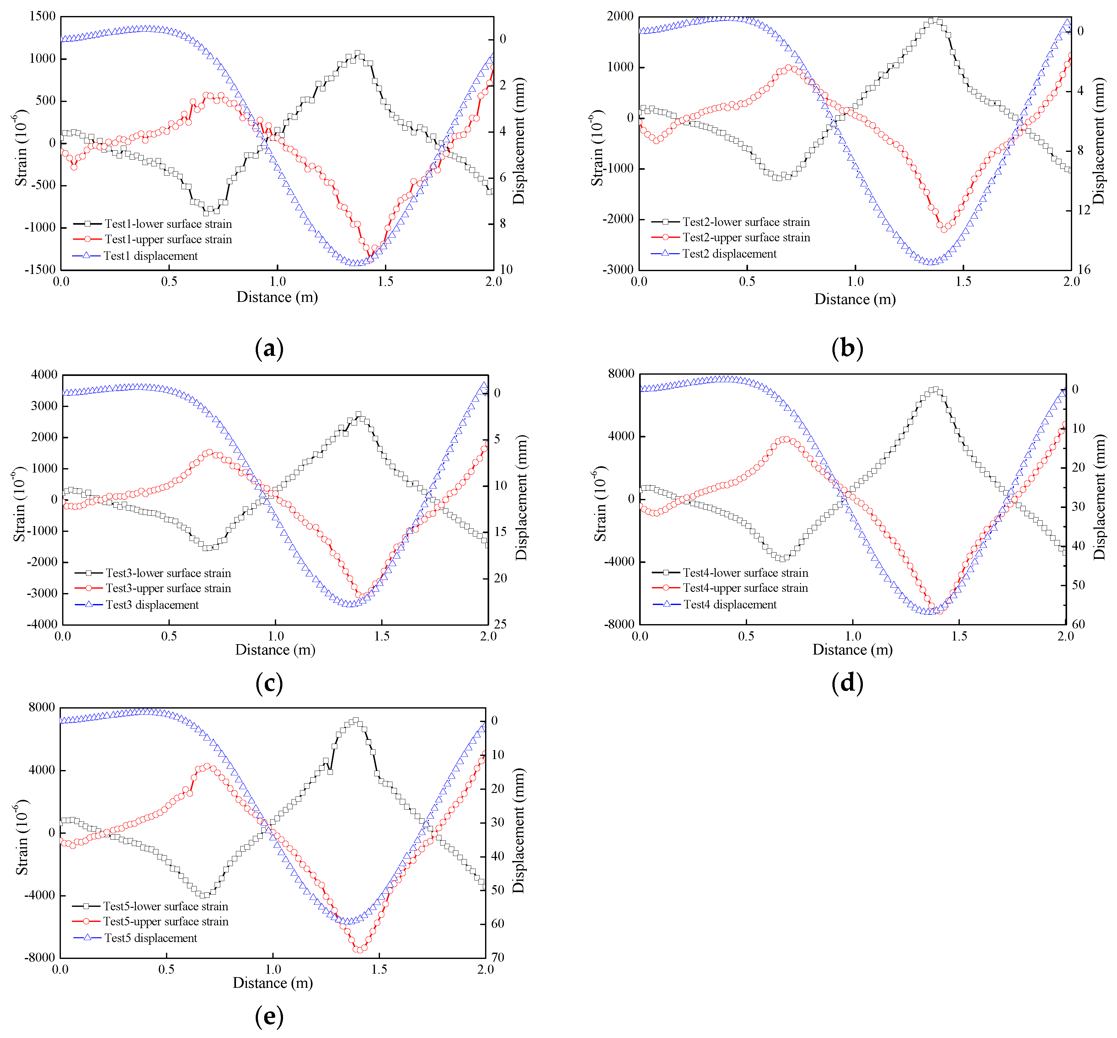
Figure 3 shows the strain and displacement curves obtained for Test 1 to Test 5. The upper and lower surface strains of the OFEB measured in different tests are generally symmetrically distributed, which is consistent with the mechanical characteristics of the beam unit under a point displacement load, indicating that the distributed optical fiber can accurately measure the strain at each point in the beam unit.
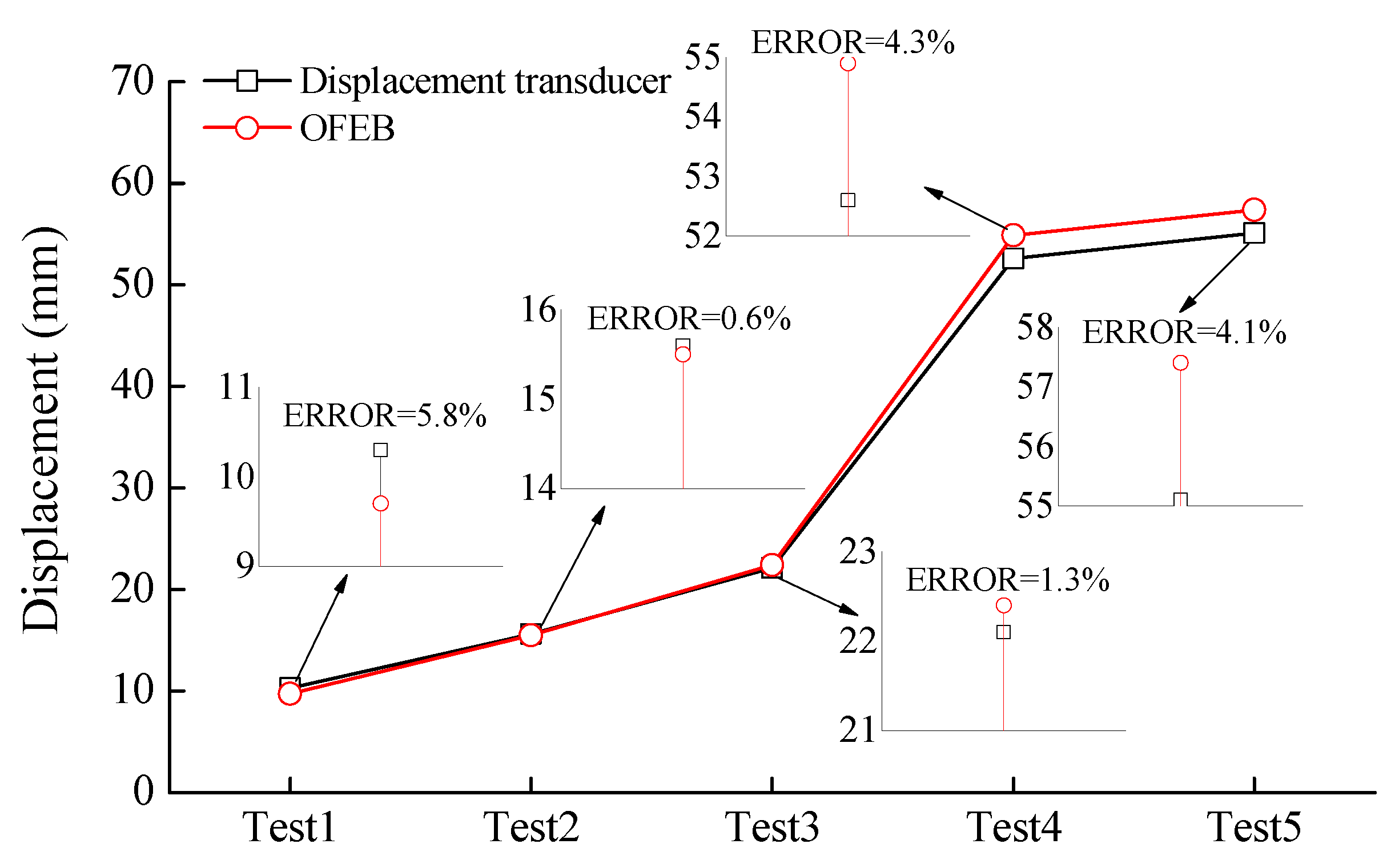
Figure 4 compares the measurements of the optical fiber and displacement sensor for the five tests. The measured settlement at B in Tests 1, 2, 3, 4, and 5 are 9.7 mm, 15.5 mm, 22.4 mm, 54.9 mm, and 57.4 mm using the optical fiber, respectively, and 10.3 mm, 15.6 mm, 22.1 mm, 52.6 mm, and 55.1 mm using the displacement sensor, respectively. The relative error between the two measurement methods ranges from 0.6% to 5.8%, which is within the allowable range. The measured settlement at A range from 0.2 mm to 1.5 mm using the optical fiber and from 0.3 mm to 1.5 mm using the displacement transducer. Thus, the results at the measurement points A and B indicate that the embedded optical fiber can accurately measure the vertical deflection of the OFEB, realizing the continuous distribution measurement of beam deflection.
3. Similarity model test of a highway subgrade
3.1. Model design
A similarity model of a subgrade was designed to simulate the lateral differential settlement of the subgrade of the Gonghe–Yushu Expressway on the Qinghai–Tibet Highway. The engineering prototype was 12.25 m wide and 4 m high. A similarity ratio of 1:10 was used considering the geometric characteristics, while neglecting the kinematic and dynamic characteristics, of the prototype. That is, a settlement deformation of 20 mm in the similarity model corresponds to a settlement deformation of 20 cm in the prototype system.
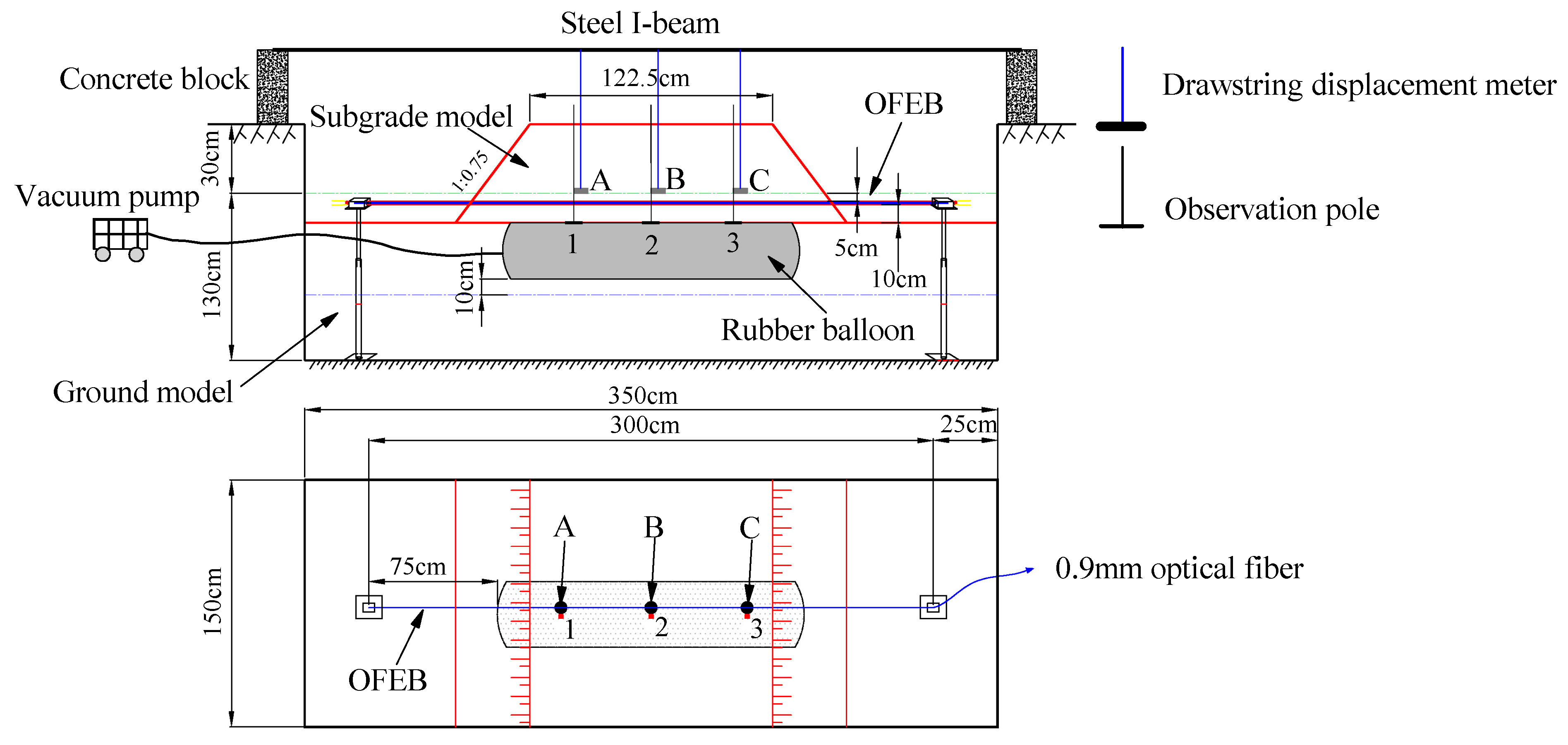
Figure 5 is a schematic of the similarity model of the subgrade, which had a height of 40 cm and a top surface with a width of 122.5 cm. A soil layer with a height of 130 cm below the subgrade was used to simulate the foundation. The soil was new loess with a maximum particle size below 0.5 mm.
The OFEB in the model test was also made of HDPE pipe with an external diameter
D of 25 mm. The two ends of the beam body were consolidated to minimize the effect of the end constraint effect. The OFEB within 25
D–30
D of the fixed supports on both sides was suspended[
37]. The effective test length of the OFEB used for the similarity model test was 3 m. Unlike in the calibration test, the upper and lower surfaces of the beam were protected by a flexible corner line against the action of the overlying soil load. As the longitudinal flexural stiffness of the corner line was very small, the influence of the corner line on the deflection deformation of the beam could be neglected.
3.2. Sensor installation and test process
In this study, a drawstring displacement transducer was used (measuring range: 1000 mm, linearity: ±0.15%). A settlement plate was fixed at the end of the beam. Three settling plates (labeled A, B, and C) were placed 5 mm above the OFEB, and the transducer motors were fixed on the I-beam at the top of the subgrade model. Three observation poles (labeled 1, 2, and 3) were mounted on the top of a rubber balloon to reflect the dilation of the balloon. The rubber balloon was 1.5 m long and 50 cm in diameter. Transverse differential settlement of the subgrade model was realized by pumping air into the rubber balloon, which was buried at the bottom of the subgrade model. A suction pipe was placed at the left side of the observation pole 1 and led from the burial position to the ground. The dilation of the rubber balloon was controlled by a vacuum pump. The test was conducted under three conditions. (1) Condition 1: the balloon was naturally exhausted to atmospheric pressure for 1 min and 30 s, and the settlement was allowed to stabilize over 1 h. (2) Condition 2: the air pump was operated for 1 min and 30 s, and the settlement was allowed to stabilize over 1 h. (3) Condition 3: the air pump was operated for 2 min, and the settlement was allowed to stabilize over 1 h.
3.3. Experimental results and analysis
Exhausting the rubber balloon during the test resulted in differential settlement at each position of the subgrade model. The OFEB deformed with the soil at the different positions.
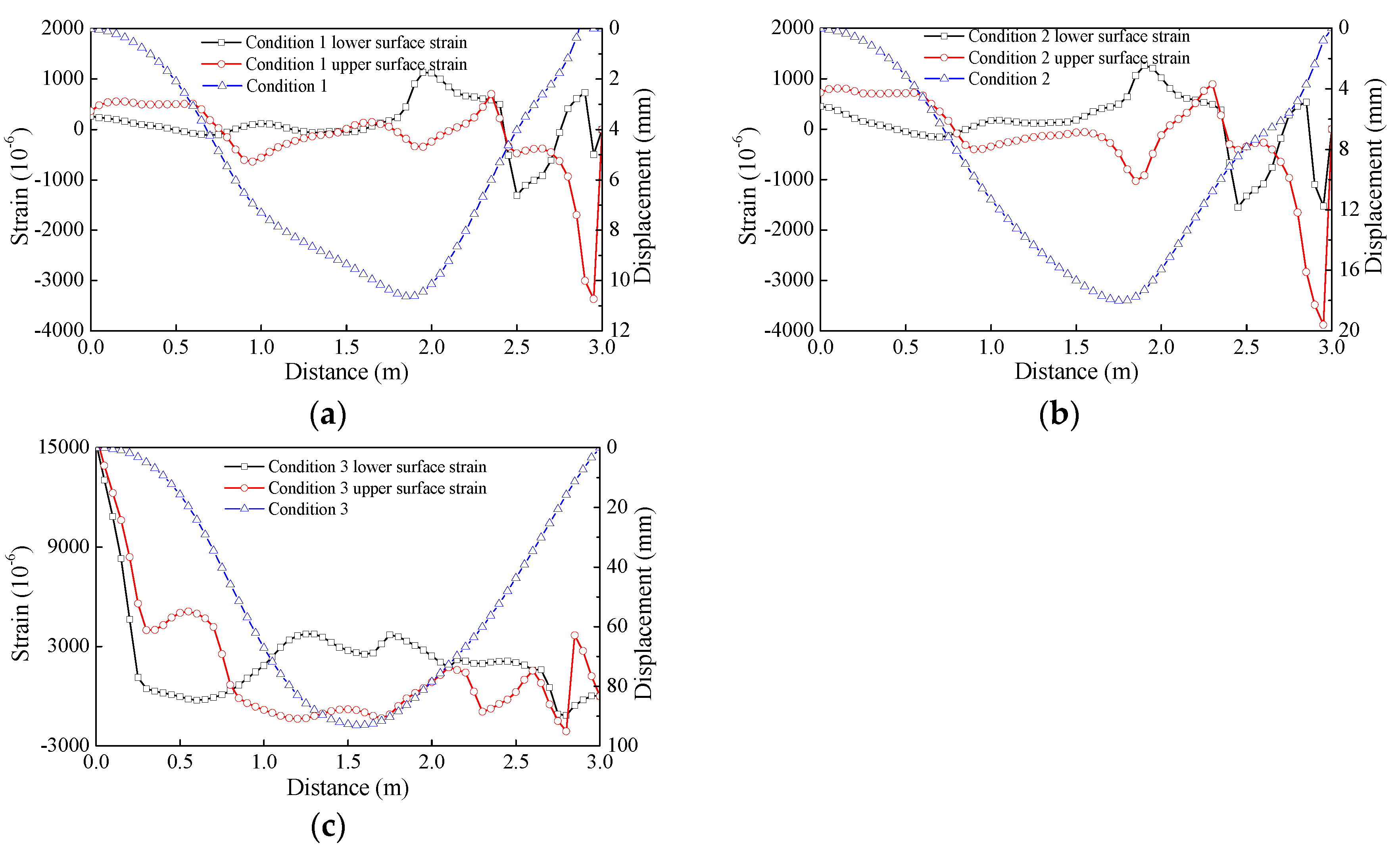
Figure 6 shows the strain and displacement curves obtained under the working conditions 1–3, and all the test results are presented in
Table 1.
Table 1 and
Figure 6 show that under the working conditions 1 and 2, a very small subgrade settlement was measured by the drawstring displacement transducer and the OFEB. This result was obtained because as the suction pipe was located at the left side of the observation pole 1, the exhaust at the observation pole 3 lagged behind that at the observation poles 1 and 2. Thus, a "pressure arch" was created in the soil layer that supported the upper soil layer. After the rubber balloon was evacuated under Condition 3, the "pressure arch" in the soil layer could no longer support the overlying soil, and the upper layer suddenly collapsed. This sharp downward subsidence resulted in a large soil deformation.
Table 2 presents the measurements obtained using the drawstring displacement transducer, which show that the last subsidence was considerably larger at the settling plate A than at the settling plates B and C.
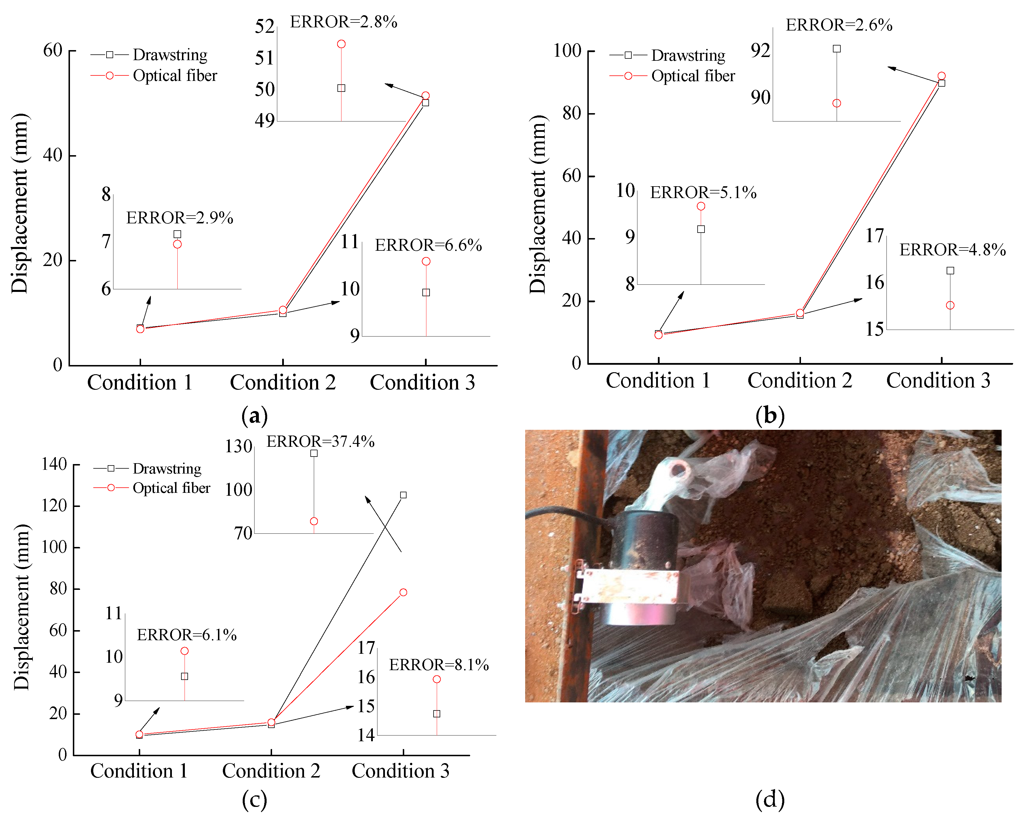
Figure 7(a)~(c) compares the measurements obtained using the optical fiber and drawstring displacement transducer under the three working conditions. The errors in the settlement measured by the optical fiber relative to the measurement by the drawstring displacement transducer are 2.9%, 2.8%, and 6.6% at Position C; 5.1%, 2.6%, and 4.8% at Position B; and 6.1%, 8.1%, and 37.4% at Position A. The errors at Positions B and C are acceptable and correspond to an OFEB measurement accuracy exceeding 93.4%. However, the OFEB measurement accuracy at Position A is considerably lower because settlement occurred at Position A before occurring at Positions B and C. Thus, uncoupling between the OFEB and subgrade soil developed rapidly, especially when the soil foundation deformed to 125.3 mm, resulting in a large difference between the measurements obtained using the optical fiber and the drawstring displacement transducer. As the subgrade soil can slip at both sides of the OFEB, the deformation between the soil and OFEB was completely uncoupled. This result is confirmed by the photo of the field test shown in
Figure 7(d): the subgrade soil at the settling plate A has completely fallen into the cavity of the rubber balloon, showing that the OFEB is only coupled with the soil over a certain settlement deformation range. The OFEB should have a wide measurement range to accurately measure subgrade settlement. As a limited number of tests were performed, the accurate measurement range of the OFEB was determined in the experiment as 0–89.77 mm, which corresponds to the measurement range for the actual scaled-up highway subgrade of 0–897.7 mm. Thus, the proposed method can meet the requirements for measuring large deformations of subgrades.
In conclusion, the calibration and model experiments show that the OFEB and the corresponding calculation method can measure subgrade settlement accurately within a certain measurement range. However, there are errors in the measurement of the subgrade settlement, the main sources of which are measurement error from the OFEB itself, such as that resulting from artificial error, the boundary constraint effect, and the OFEB bending stiffness, and the beam–soil interface friction coefficient, as well as deformation transfer resulting from the uncoupling of the OFEB and the soil foundation. These errors can be minimized by optimizing the industrial manufacturing process of the OFEB, that is, by relaxing the end constraint to create simply supported beams or cantilever beams, optimizing the material and size parameters of the beam body, and enhancing interfacial friction.
4. Numerical simulation verification and analysis
Coupling of the beam material, beam size parameters, and soil parameters, as well as the boundary conditions on the beam, make it difficult to determine the measurement range and accuracy of the OFEB. Thus, a numerical simulation was performed to investigate the coupling and coordinated deformation capacity of the beam and soil. Optimal material and size parameters were determined to increase the coupling deformation capacity of the beam and soil, and the applicability of the OFEB for measuring large-scale settlement and deformation of a subgrade was evaluated. A finite element analysis of an outdoor HDPE pipe model was carried out using ABAQUS. An analysis was performed to determine the influence of key design parameters for the shape and material of the pipe and interfacial contact (as represented by the pipe diameter D, the elastic moduli E of the pipe and soil, and the friction coefficient μ between the pipe and soil) on the OFEB measurement range.
4.1. Numerical model
The soil used in the similarity model test was a near-surface loess. A strain softening/hardening model was used in conjunction with the Mohr–Coulomb failure criterion, an internal friction angle of the soil of 20°, an expansion angle of 0°, and a cohesion of 0.5 MPa. HDPE is a nonlinear viscoelastic material. The material parameters of the soil and the pipe are listed in
Table 2.
The same dimensions were used in the numerical model as in the similarity model test. The natural ground soil model was 3.5 m long, 1 m wide, and 1.6 m deep. The subgrade soil model had a bottom width of 1.975 m, a top width of 1.225 m, and a height of 0.5 m. The HDPE pipe was 3 m long. The pipe and soil were considered to be in hard contact, constraints perpendicular to the surface were applied to the model side, fixed constraints were applied to the ground model, and free constraints were applied to the subgrade slope. The cell death technique was used to simulate the gap at the bottom of subgrade created by pumping the rubber balloon.
Simulations were performed using different HDPE pipe diameters (the ratio of the wall thickness to the pipe diameter was 1:10), elastic moduli of the pipe and soil, and friction coefficients between the pipe and soil. The working conditions considered in the simulation are shown in
Table 3.
4.2. Numerical results and analysis
The maximum vertical displacement at the top of the span, the friction stress of the pipe–soil contact surface, and the maximum contact opening of the pipe–soil contact surface before the HDPE pipe enters the yield stage were analyzed under different working conditions. We consider the working condition C9 as an example.
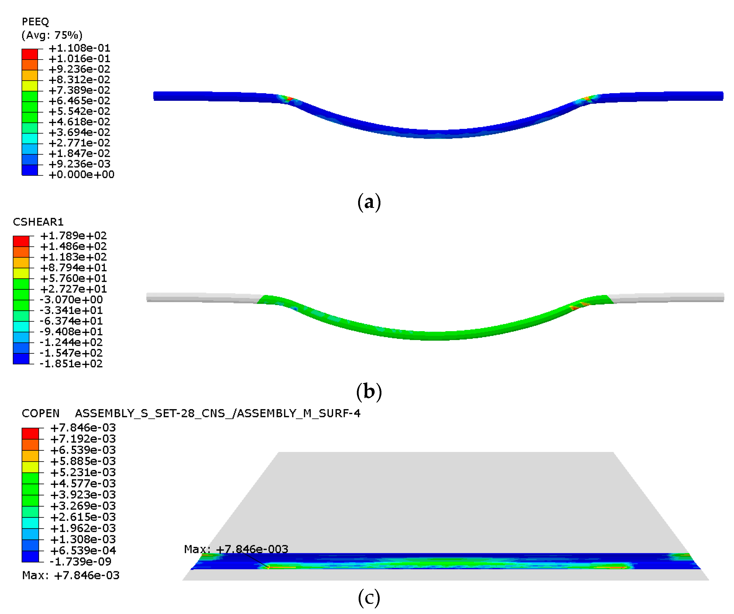
Figure 8 shows the plastic zone of the HDPE pipe, the friction stress of the contact surface, and the clearance distance of the pipe–soil contact surface before the point in the simulation when the model does not converge.
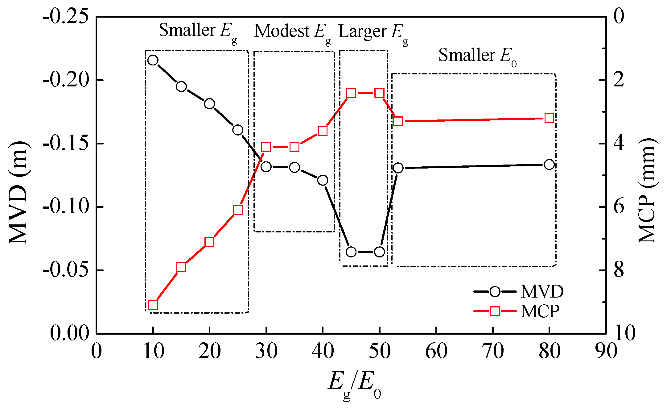
Figure 8(a) shows that the HDPE pipe first starts to yield at the junction of the subsidence area and nonsubsidence area and eventually yields at the midspan position. Thus, the junction of the subsidence and nonsubsidence areas can be taken as the section of the pipe body over which yielding should be controlled. The maximum vertical displacement (MVD) over the span and the maximum contact opening (MCP) between the pipe and the soil surface before the HDPE pipe starts to yield are used to analyze the degree of coordinated deformation between the pipe and the soil.
Figure 8(b) shows that the contact friction stress reaches a maximum in the yield control section and then gradually decreases to the midspan region.
Figure 8(c) shows that there is a large clearance distance only in the yield control section within a small range at the top and bottom of the pipeline. As the contact stress and friction stress near the yield control section are relatively large, the junction between the subsidence and nonsubsidence areas is more likely to have a larger displacement. The clearance between the pipe and soil is very small at most positions, indicating that most sections of the pipe are in good contact with the soil mass and the pipe deforms effectively with the soil mass.
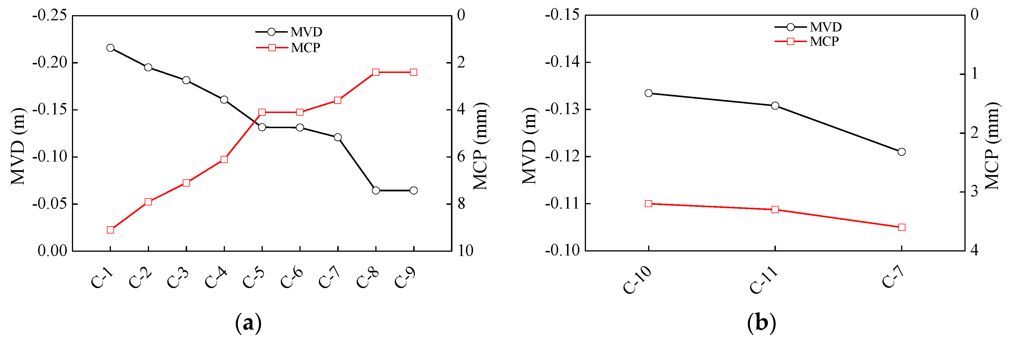
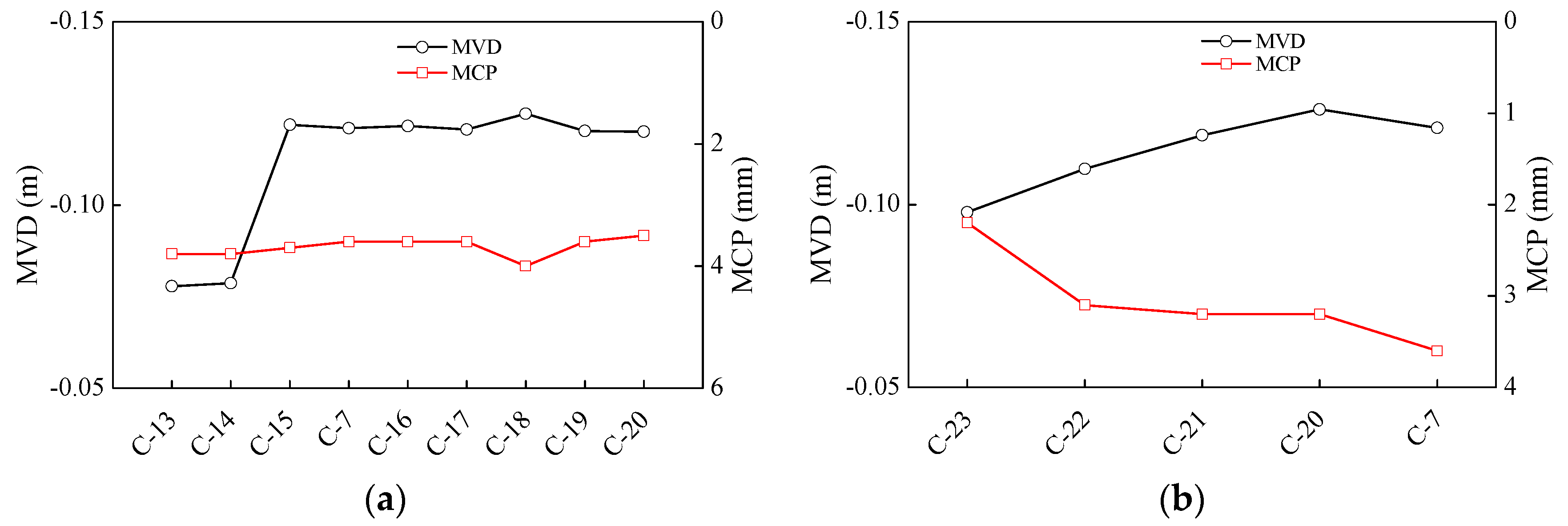
Figure 9(a) shows the MVD and MCP before yielding under the working conditions C1–C9. The MVD decreases as the elastic modulus of the pipe increases. Thus, reducing the elastic modulus of the HDPE pipe can effectively increase the OFEB measurement range; however, the increase in the MCP weakens the coupling between the pipe and soil and cause the control section of the pipe to enter the yield stage earlier. Although the displacement could be measured before the yield stage, the plastic yield section near the yield control section of the pipe would gradually increase in size and ultimately affect the deformation measurement accuracy at each position.
Figure 9(b) shows the MVD and MCP before yielding under the working conditions C7, C10, and C11. As the elastic modulus of the soil increases, the MVD decreases and the MCP increases. Thus, increasing the elastic modulus of the soil has a limited effect on improving codeformation of the pipe and soil.
The most suitable ratio of the elastic moduli (the pipe elastic modulus
Eg normalized by the soil elastic modulus
E0) under the optimal code formation condition was determined.
Figure 10 shows the MVD and MCP before yielding versus the normalized elastic modulus. At excessively small or large
Eg values, the MVD exhibits an opposite trend in the normalized elastic modulus to the MCP. The coupling performance between the pipe and soil is poor over a large measurement range. For moderate
Eg values or small
E0 values, the coupling between the pipe and soil is good over a reasonable measurement range. The elastic modulus of a road bed after completion of construction is generally standardized controlled. As the
Eg is the main influence factor for the performance of the coupling between the pipe and soil, it is recommended that the ratio between
Eg and
E0 should be controlled to between 30 and 40.
Figure 11(a) shows the MVD and MCP before yielding under the working conditions C7 and C12–C19. The MVD increases with the friction coefficient
μ. However, for
μ larger than 0.3, the MVD changes very little with
μ because the friction stress at the pipe–soil contact surface increases with the friction coefficient, such that the pipe tends to yield more easily at the junction between the subsidence and nonsubsidence areas. The MCP essentially remains constant as the friction coefficient increases, showing that modifying the friction coefficient has a limited effect on the contact opening between the pipe and the soil surface. Thus, sit is recommended that a moderate friction coefficient be selected.
Figure 11(b) shows the MVD and MCP before yielding under the working conditions C7 and C20–C23. As the pipe diameter
D increases, the MVD increases and the MCP decreases. The pipe diameter affects the degree of coupling between the pipe and soil because the smaller the pipe diameter is, the lower the bending stiffness of the pipe body is, making the HDPE pipe more likely to deform with the soil. However, as the system cost increases with the pipe diameter, increasing the pipe diameter is not a feasible strategy for improving the MVD. Thus,
D = 25 or 32 mm is recommended.
5. Conclusions
An optical-fiber-embedded beam(OFEB) based on BOTDA test technology was proposed in this study. The study results provide a theoretical and practical basis for the application of optical-fiber sensing technology to monitoring subgrade settlement. A model test and numerical simulation were carried out to assess the applicability and monitoring accuracy of the OFEB. The major conclusions are given below.
(1) The results of a calibration test show that beam deflection can be accurately measured by the embedded optical fiber, where the relative error between the measurements of the optical fiber and a displacement transducer is approximately 5%. The OFEB can be used to make dense displacement measurements and is therefore suitable for monitoring large-scale settlement of a subgrade.
(2) The results of a test on a subgrade similarity model test show that the OFEB can measure subgrade settlement and settlement variations before the subgrade soil slips or decouples from the beam. The relative error between the measurements of the optical fiber and displacement transducer is less than 8.1%. The main sources of error are artificial error, the effect of the boundary constraint, and the pipe bending stiffness. However, the OFEB is not suitable for measuring large subgrade settlement.
(3) A numerical simulation shows that the optimal ratio of the elastic moduli of the beam and soil lies between 30 and 40. The measurement range of the OFEB can be appropriately increased by selecting a small-diameter beam and improving the coupling between the beam and soil. Increasing the interfacial friction can only improve the beam–soil coupling performance to a limited extent.
Preliminary experiments based on finite fixed-point calibration were carried out in this study to assess the suitability and accuracy of the OFEB for monitoring subgrade settlement. The maximum measurement range was identified as 89.77 mm. Further studies are needed to verify the applicability of the optical-fiber-embedded beam for detecting realistically large subgrade settlement. The beam fabrication process could be mechanized to achieve “real optical-fiber implantation.”
Author Contributions
Conceptualization, L.Z., and Y.K.; methodology, L.Z., and Y.K.; software, L.Z.; validation, L.Z., and Z.Lg.; formal analysis, Y.K.; investigation, L.Z., and Y.K.; resources, Z.Lg.; data curation, L.Z., Y.K. and Z.Lg.; writing—original draft preparation, L.Z., and Y.K.; writing—review and editing, Y.K., and Z.Lg.; visualization, L.Z., Y.K., and Z.Lg.; supervision, Z.Lg.; project administration, Z.Lg.; funding acquisition, Z.Lg., and Y.K. All authors have read and agreed to the published version of the manuscript.
Funding
This research was funded by Shaanxi Province Technology Innovation Guidance Special Project, Grant No. 2021CGBX-38, the Second Tibetan Plateau Scientific Expedition and Research (STEP) Program, Grant No.2019QZKK0905, CCCC Scientific and Technological Research Program, Grant No. 2020-ZJKJ-PTJS04, 2020-ZJKJ-QNCX09, 2020-ZJKJ-PTJS12.
Institutional Review Board Statement
Not applicable.
Data Availability Statement
The data presented in this study are available on request from the corresponding authors.
Conflicts of Interest
The authors declare no conflict of interest.
References
- Feng, S.X.; Lei, H.Y. A settlement prediction model considering tidal loading and traffic loading of soft soil subgrade. Computers and Geotechnics 2022, 144, 104639. [Google Scholar] [CrossRef]
- Zhao, H. Y.; Indraratna, B.; Ngo, T. Numerical simulation of the effect of moving loads on saturated subgrade soil. Computers and Geotechnics 2021, 131, 103930. [Google Scholar] [CrossRef]
- Liu, X.L.; Chen, Y.X.; Meng, Q.L.; Song, J.B.; Zhang, X.M. Thaw settlement of runways in permafrost regions under aircraft load. European Journal of Environmental and Civil Engineering 2023, 27(1), 500–518. [Google Scholar] [CrossRef]
- Bado, M. F.; Casas, J. R. A review of recent distributed optical fiber sensors applications for civil engineering structural health monitoring. Sensors 2021, 21(5), 1818. [Google Scholar] [CrossRef] [PubMed]
- Xing, X.M.; Chang, H. C. , Chen, L.F.; Zhang, J.H.; Yuan, Z.H.; Shi, Z.N. Radar interferometry time series to investigate deformation of soft clay subgrade settlement—A case study of Lungui Highway, China. Remote Sensing 2019, 11(4), 429. [Google Scholar] [CrossRef]
- Dai, K.; Liu, G.; Li, Z.; Ma, D.; Wang, X.; Zhang, B.; Tang, J.; Li, G. Monitoring highway stability in permafrost regions with X-band temporary scatterers stacking InSAR. Sensors 2018, 18(6), 1876. [Google Scholar] [CrossRef] [PubMed]
- Zhang, W.P. Application of 3D laser scanning in deformation detection of Qinghai-Tibet highway subgrade. Chang' an University, Xi’an, China, 2017.
- Min, Y.; Tao, J.; Ren, W. A high-precision online monitoring system for surface settlement imaging of railway subgrade. Measurement 2020, 159, 107707. [Google Scholar] [CrossRef]
- Zhu, H. H.; Shi, B.; Zhang, C. C. FBG-based monitoring of geohazards: current status and trends. Sensors 2017, 17(3), 452. [Google Scholar] [CrossRef]
- Liu, J.; Wang, Y.; Lu, Y.; Wei, J.H.; Kanungo, D. P. Application of distributed optical fiber sensing technique in monitoring the ground deformation. Journal of Sensors, 2017, 2017, 1–11. [Google Scholar] [CrossRef]
- Horiguchi, T.; Kurashima, T.; Tateda, M. Tensile strain dependence of Brillouin frequency shift in silica optical fibers. IEEE Photonics Technology Letters 1989, 1(5), 107–108. [Google Scholar] [CrossRef]
- Barrias, A.; Casas, J. R.; Villalba, S. A review of distributed optical fiber sensors for civil engineering applications. Sensors 2016, 16(5), 748. [Google Scholar] [CrossRef] [PubMed]
- Dong, Y. K. High-performance distributed Brillouin optical fiber sensing. Photonic Sensors 2021, 11, 69–90. [Google Scholar] [CrossRef]
- Dong, Y. K.; Zhang, H.Y.; Chen, L.; Bao, X.Y. 2 cm spatial-resolution and 2 km range Brillouin optical fiber sensor using a transient differential pulse pair. Applied optics 2012, 51(9), 1229–1235. [Google Scholar] [CrossRef] [PubMed]
- Glišić, B.; Posenato, D.; Inaudi, D. Integrity monitoring of an old steel bridge using fiber optic distributed sensors based on Brillouin scattering. In Nondestructive characterization for composite materials, aerospace engineering, civil infrastructure, and homeland security 2007, 6531, 210–217. [Google Scholar]
- Xu, J.L.; Dong, Y.K.; Zhang, Z.H.; Li, S.L.; He, S.Y.; Li, H. Full scale strain monitoring of a suspension bridge using high performance distributed fiber optic sensors. Measurement Science and Technology 2016, 27(12), 124017. [Google Scholar] [CrossRef]
- Ye, C.; Butler, L. J.; Elshafie, M. Z.; Middleton, C. R. Evaluating prestress losses in a prestressed concrete girder railway bridge using distributed and discrete fibre optic sensors. Construction and Building Materials 2020, 247, 118518. [Google Scholar] [CrossRef]
- Seo, H. Monitoring of CFA pile test using three dimensional laser scanning and distributed fiber optic sensors. Optics and Lasers in Engineering 2020, 30, 106089. [Google Scholar] [CrossRef]
- Kania, J. G.; Sorensen, K. K.; Fellenius, B. H. Application of distributed fibre optic cables in piles. Geotechnical Engineering 2020, 51(1), 94–102. [Google Scholar]
- Xu, D. S.; Yin, J. H.; Liu, H. B. A new measurement approach for deflection monitoring of large-scale bored piles using distributed fiber sensing technology. Measurement 2018, 117, 444–454. [Google Scholar] [CrossRef]
- Gao, L.; Han, C.; Xu, Z.Q.; Jin, Y.J.; Yan, J.Q. Experimental study on deformation monitoring of bored pile based on BOTDR. Applied Sciences 2019, 9(12), 2435. [Google Scholar] [CrossRef]
- Wang, H.P.; Xiang, P.; Jiang, L.Z. Optical Fiber Sensor Based In-Field Structural Performance Monitoring of Multilayered Asphalt Pavement, J. Lightwave Technol 2018. 36, 3624–3632. [CrossRef]
- Rabaiotti, C.; Hauswirth, D.; Fischli, F.; Facchini, M.; Puzrin, A. Structural health monitoring of airfield pavements using distributed fiber-optics sensing. In Proceedings of the 4th Conf. on Smart Monitoring, Assessment and Rehabilitation of Civil Structures (SMAR 2017) , Zürich, Switzerland 2017. 13-15.
- Schenato, L.; Camporese, M.; Bersan, S.; Cola, S.; Galtarossa, A.; Pasuto, A.; Palmieri, L. High density distributed strain sensing of landslide in large scale physical model. In 2017 25th Optical Fiber Sensors Conference (OFS) 2017, 1–4. [Google Scholar]
- Zhang, D.; Wang, J.C.; Zhang, P.S.; Shi, B. Internal strain monitoring for coal mining similarity model based on distributed fiber optical sensing. Measurement 2017, 97, 234–241. [Google Scholar] [CrossRef]
- Chai, J.; Lei, W.; Du, W.; Yuan, Q.; Zhu, L.; Zhang, D.; Li, H. Experimental study on distributed optical fiber sensing monitoring for ground surface deformation in extra-thick coal seam mining under ultra-thick conglomerate. Optical Fiber Technology 2019, 53, 102006. [Google Scholar] [CrossRef]
- Wu, J. H.; Shi, B.; Cao, D. F.; Jiang, H. T.; Wang, X. F.; Gu, K. Model test of soil deformation response to draining-recharging conditions based on DFOS. Engineering Geology 2017, 226, 107–121. [Google Scholar] [CrossRef]
- Zhang, C. C.; Shi, B.; Gu, K.; Liu, S. P.; Wu, J. H.; Zhang, S.; Wei, G. Q. Vertically distributed sensing of deformation using fiber optic sensing. Geophysical Research Letters 2018, 45(21), 11732–11741. [Google Scholar] [CrossRef]
- Liu, J.; Song, Z.Z.; Lu, Y.; Bai, Y.X.; Qian, W.; Kanungo, D. P.; Chen, Z.H.; Wang, Y. Monitoring of vertical deformation response to water draining–recharging conditions using BOFDA-based distributed optical fiber sensors. Environmental Earth Sciences 2019, 78, 1–11. [Google Scholar] [CrossRef]
- Meng, S.J.; Sun, Y.Q.; Wang, M. Fiber Bragg grating sensors for subgrade deformation monitoring in seasonally frozen regions. Structural Control and Health Monitoring 2020, 27(1), e2472. [Google Scholar] [CrossRef]
- Cheng, Y.K.; Shi, Z.W. Permanent Deformation and Temperature Monitoring of Subgrades Using Fiber Bragg Grating Sensing Technology. Journal of Sensors 2021, 1–15. [Google Scholar] [CrossRef]
- Zhang, D.Q.; He, J.P.; Xue, Y.; Xu, J.; Xu, X.J. Investigation of settlement monitoring method based on distributed Brillouin fiber optical sensor. Measurement 2019, 134, 118–122. [Google Scholar] [CrossRef]
- Wu, H.; Zhu, H. H.; Zhang, C. C.; Zhou, G. Y.; Zhu, B.; Zhang, W.; Azarafza, M. Strain integration-based soil shear displacement measurement using high-resolution strain sensing technology. Measurement 2020, 166, 108210. [Google Scholar] [CrossRef]
- Liu, S. P.; Gu, K.; Zhang, C. C.; Shi, B. Experimental research on strain transfer behavior of fiber-optic cable embedded in soil using distributed strain sensing. International Journal of Geomechanics 2021, 21(10), 04021190. [Google Scholar] [CrossRef]
- Zhang, D.; Xu, Q.; Bezuijen, A.; Zheng, G.; Wang, H.X. Internal deformation monitoring for centrifuge slope model with embedded FBG arrays. Landslides 2017, 14, 407–417. [Google Scholar] [CrossRef]
- Zhang, C. C.; Zhu, H. H.; Shi, B. Role of the interface between distributed fibre optic strain sensor and soil in ground deformation measurement. Scientific Reports 2016, 6(1), 36469. [Google Scholar] [CrossRef] [PubMed]
- Shi, Y. X. Response analysis for buried pipelines subjected to the settlement. Dalian University of Technology, Dalian, China, 2007.
|
Disclaimer/Publisher’s Note: The statements, opinions and data contained in all publications are solely those of the individual author(s) and contributor(s) and not of MDPI and/or the editor(s). MDPI and/or the editor(s) disclaim responsibility for any injury to people or property resulting from any ideas, methods, instructions or products referred to in the content. |
© 2023 by the authors. Licensee MDPI, Basel, Switzerland. This article is an open access article distributed under the terms and conditions of the Creative Commons Attribution (CC BY) license (https://creativecommons.org/licenses/by/4.0/).

