1. Introduction
Uncrewed Aerial Vehicles (UAVs) have become increasingly popular in various applications, including search and rescue (SAR) activities. In the aftermath of a nuclear accident, SAR missions are critical to assess the extent of damage, locate survivors, and monitor radiation levels [
1,
2]. However, the high radiation levels in such environments pose a significant risk to the electronic components of UAVs, potentially leading to mission failure. This paper presents a dynamic probabilistic risk assessment (D-PRA) approach to assess the survivability of commercial off-the-shelf (COTS) drones in radiological SAR operations and identify the most vulnerable components for radiation hardening (RAD-HARD) improvements.
The use of COTS drones in SAR missions offers several advantages, such as cost-effectiveness, rapid deployment, and ease of operation. However, these drones are not typically designed to withstand the harsh radiation environments encountered in nuclear accidents. On the other hand, radiation hardened UAVs may be employed, but all use cases may justify their use. Influencing factors include availability, cost, and mission-specific requirements. Therefore, it is essential to develop a systematic approach to assess the survivability of COTS drones in nuclear SAR missions to identify the most critical components for RAD-HARD improvements. Probabilistic Risk Assessment (PRA) is a well-established methodology used in the nuclear engineering field to evaluate the safety and reliability of nuclear power plants. PRA techniques have been successfully applied to various complex systems, including space missions, aviation, and chemical plants. In this paper, we extend the application of PRA to assess the survivability of COTS drones in nuclear SAR missions.
PRA techniques have been established to evaluate risks by identifying potential failure scenarios, assessing their likelihood, and determining the consequences if these failures occur. Consequently, risk is formally expressed as a comprehensive set of
triplets that include a scenario description
, its probability
, and the consequences, i.e. the resulting damage measure or evaluation metric
:
PRA offers a comprehensive approach that is well-suited for modeling intricate dependencies and failure modes in static systems. These methods have significantly contributed to ensuring safety in current nuclear and aerospace operations. Conventional PRA approaches involve sequence-based modeling where initiating events are chosen, conditional event progressions are analyzed, leading to end states of interest. By incorporating consequence information into these PRA models, frequency-consequence curves can be formulated [
3]. In event tree analysis, probabilities are assigned to functional events depicting various components, systems, or operator actions using fault trees. These probabilities take into account either time-dependent or on-demand failure modes given predetermined mission durations [
4]. Although this approach offers more insights than traditional deterministic methods, it may not be sufficient for accurately modeling systems that exhibit intricate time- and event-based dependencies or feedback mechanisms. For instance, certain events might have failure rates that evolve over time. In such cases, a sophisticated modeling technique is necessary to conservatively divide the timeframe into longer intervals so as to properly establish basic event failure rates and mission durations. Integrating additional dynamic methods within PRA models can lead to improved accuracy when dealing with complex temporal dependencies among system elements.
The proposed D-PRA approach utilizes OpenEPL error propagation library to model sequences leading to Loss of Mission (LOM) and Loss of Vehicle (LOV) scenarios due to component failures in the drone's navigation system. Radiation effects are simulated by calculating the total ionizing dose (TID) against the permissible limit per component, and errors are propagated within the electronic hardware and software blocks to quantify navigation system availability per radiation zone. The proposed methods are integrated into the traditional event tree/fault tree approach to provide a demonstrative assessment of the drone's survivability in nuclear SAR missions.
The remainder of this paper is organized as follows:
Section 2 provides a brief overview of the problem scope and the methodology behind the proposed solution. This includes the proposed D-PRA approach, including the modeling of radiation effects on electronic components and the integration of dynamic failure scenarios.
Section 3 presents a case study demonstrating the application of the proposed approach to a COTS drone system.
Section 4 discusses the results and their implications for drone design and selection in nuclear SAR missions. Finally,
Section 5 concludes the paper and outlines ideas for future research directions.
2. Methodology
In this section, we provide a brief overview of the problem scope and the methodology behind our proposed solution for assessing COTS drone survivability in nuclear SAR missions. We introduce a few terms within resilience ontology in the context of temporal logic using Kripke structure notation to model time-dependent risk [
5,
6,
7,
8]. The formal equation and definitions are introduced in Equation (2) and
Table 1.
A system
consists of states
that transition along a bounded, but countably infinite long path
, starting with the initial state
.
is the transition relation that maps all the valid state transitions. An equivalent definition can be expressed using the edge list
, which forms our alphabet. Traversal of path
produces words
. This allows us to build a grammar, with which we can define events, or system properties, and emergent behaviors. This grammar can includes words of our choosing, some examples are listed in in
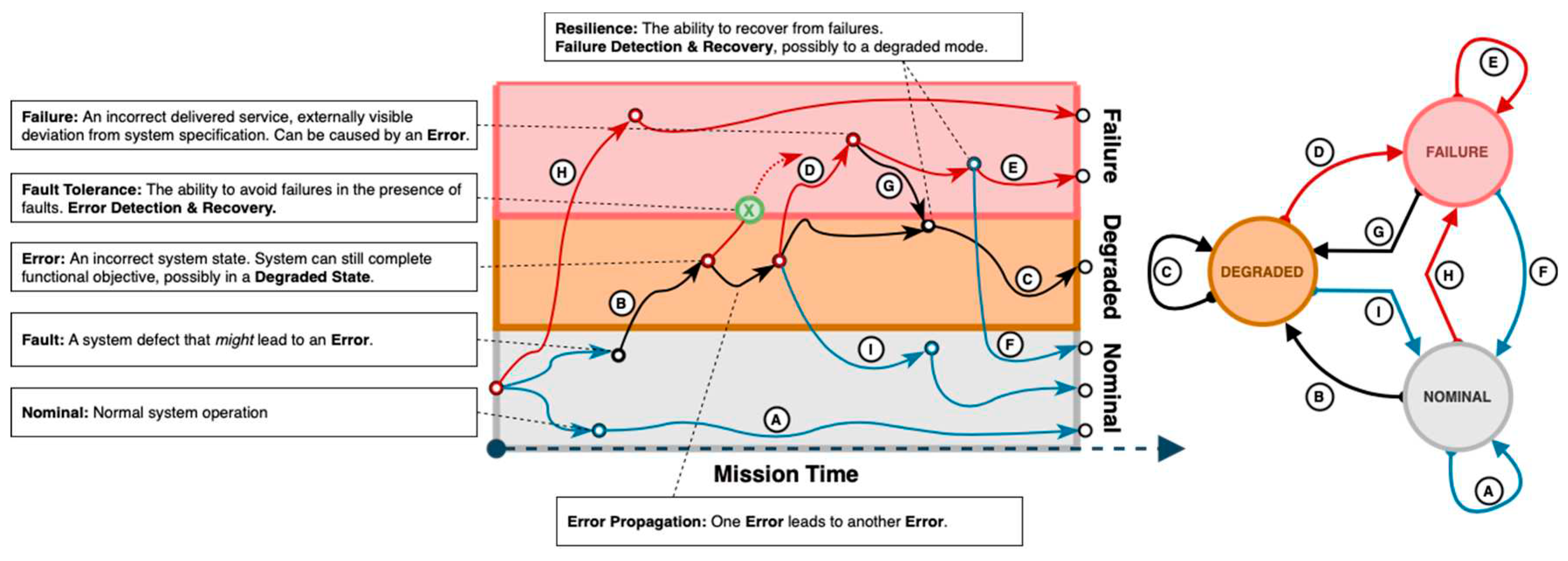
Table 2. By extension, each trajectory, or word is expressible in a temporal sense, as depicted in
Figure 1 [
9].
In certain situations, traditional and dynamic PRA methods may need to be supplemented with specialized analysis techniques for modeling the systems that involve error propagation failure modes, or incorporate multiple failure paths, such as the example in the previous section [
10]. Tracking the propagation of errors from discrete sub-components to system or functional levels in such systems presents a unique challenge. The dual-graph error propagation method (DEPM) enables the separate modeling of data flows and control flows within a system [
11]. In DEPM, we consider a system as independent, and discrete elements, which can be sensor modules, or software blocks in a mechatronic system [
12]. When a fault activates, it can propagate to connected elements, which may corrupt data, or alter the control and data flows. We present the DEPM formalism with an example in the following figures.
Flows from an element may branch erroneously, depending on its corresponding failure rates/probabilities. By extension, error propagation analyses can simulate single-event upsets (SEUs). To perform quantitative evaluations, we transform our DEPM models into continuous time (CTMCs) or discrete-time Markov Chains (DTMCs), depending on the use case.
Figure 2 and
Table 4 illustrate an example DEPM with associated conditional logic expressions.
The DEPM model in
Figure 2, a depicts execution of serial code. Assembly operations, represented as elements A, B, and C, read and write data variables 1, 2, and to and from CPU registers. Element A changes variables 1 and 3. Elements B and C change variables 2 and 4. Element B reads from data variable 1 while element C reads from both variable 2 as well as variable 3.
This DEPM computes the probability that the output variable, data variable 4, is corrupted. Given that SEUs are stochastic in nature, this may occur at any time [
13]. To achieve this goal, expressions can be evaluated by employing quantifiable Boolean formulae (QBF) evaluating satisfiability solvers [
14,
15]. Relevant metrics like the mean time to failure (MTTF), the number of total failures, and time-dependent failure probability, can be quantified directly using formal verification and model checking methods. Since it is based on probabilistic modeling checking, DEPM is better suited for modeling the behavior of smaller, but highly interdependent systems, as compared to traditional methods like fault trees and Markov chains.
3. Demonstration Case
In this demonstration case, we consider a COTS drone equipped with a navigation system, communication system, and radiation sensor payload. The drone's primary mission is to perform SAR activities in a nuclear-contaminated environment, which includes monitoring radiation levels, identifying damaged infrastructure, and locating survivors. The drone's navigation system comprises a power subsystem, inertial measurement unit (IMU) sensors, positioning sensors, and a Kalman filter. The drone is tasked with flying over a predefined search area, which is divided into three zones with varying radiation levels. The drone starts its mission in the low radiation zone (Zone A), transitions to the medium radiation zone (Zone B), and finally enters the high radiation zone (Zone C) before returning to the base. Radiation levels in Zone A are based on background radiation[
16,
17]. Radiation levels in Zone B and C are sourced from samples in and around Unit 4 and surrounding buildings at the Chernobyl nuclear power plant (NPP) shortly after explosion [
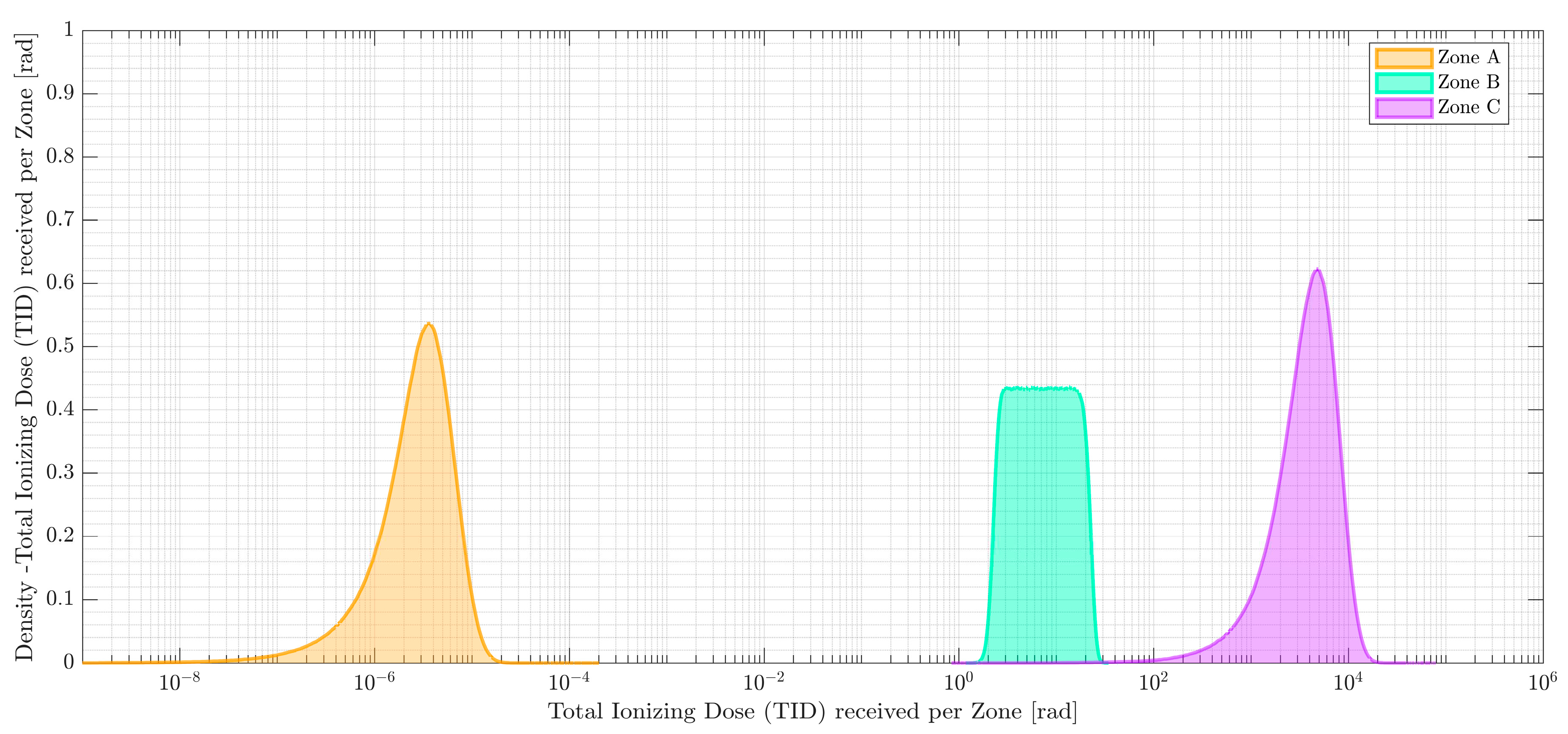
18]. Since mission success is dependent on the UAV successfully performing SAR activities for each zone before Loss of Vehicle (LOV) occurs, the analysis is finished once the drone completes its mission objectives in Zone C. The absorbed dose rates, time in each zone, and total absorbed dose are sampled from a truncated normal distribution
2 and a loguniform distribution
3, listed in
Table 5. The proposed approach is applied to assess the drone's survivability in each radiation zone by considering the potential failure scenarios due to radiation-induced component failures. TID is calculated for each component in the drone's navigation system and compared against the component's permissible limit to determine the likelihood of failure.
3.1. Scenario Description
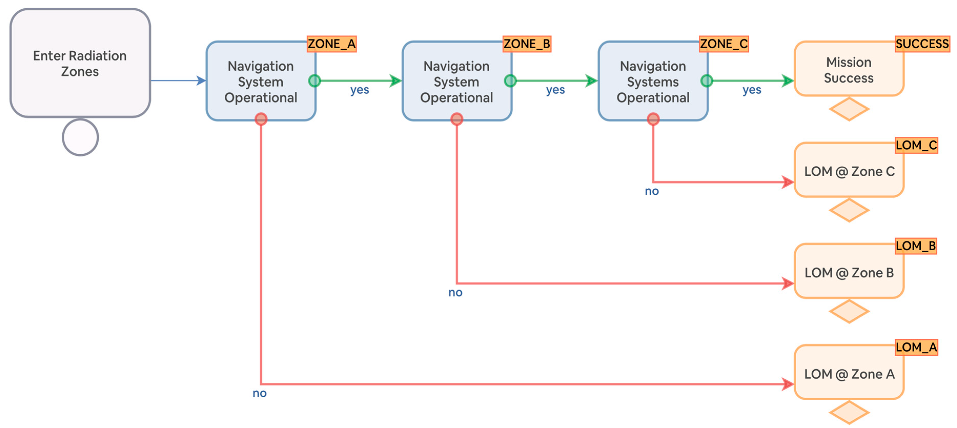
The event tree for the drone's mission is constructed based on the sequence of events that the drone is expected to encounter during its mission. Starting with the initiating event, the likelihood of navigation system availability is computed for zones A, B, and C. At each functional event, the tree branches into two outcomes: success or failure. The success branch leads to the next event in the sequence, while the failure branch leads to a Loss of Mission (LOM) end state. The failure probabilities at each node are calculated using the navigation system fault tree.
Figure 4 illustrates this event tree, modeled in the OpenPRA framework [
19].
3.2. Assumptions and Simplifications
In order to concentrate on the methodology presented, we have made several assumptions and simplifications. These are necessary to streamline the discussion and focus on the core concepts, but it's important to note that they may limit the comprehensiveness of the model.
Firstly, the event tree depicted in
Figure 4 only considers the availability of the navigation system. A more comprehensive model would take into account all components of the UAV and their interdependencies, including the potential for common cause failures (CCFs). As a result, the baseline failure probabilities presented in this study may appear lower than they would be in a more complex model that includes CCFs. Secondly, when mechatronic systems are exposed to radiation environments, they can fail due to a variety of mechanisms. These include TID effects, displacement damage, and single-event effects (SEEs). In this study, we only consider TID effects, which are the cumulative effects of ionizing radiation on materials and devices. Other failure mechanisms are not considered in this model. Thirdly, our model does not take into account the potential impact of weather conditions or terrain on the drone's ability to navigate each zone. These factors could significantly affect the drone's performance and the likelihood of mission success. Lastly, our model does not factor in the potential for human error in drone operation. In real-world scenarios, human error can significantly contribute to mission failure. However, incorporating such effects would add a layer of complexity that is beyond the scope of this study.
3.3. Navigation System Fault Tree
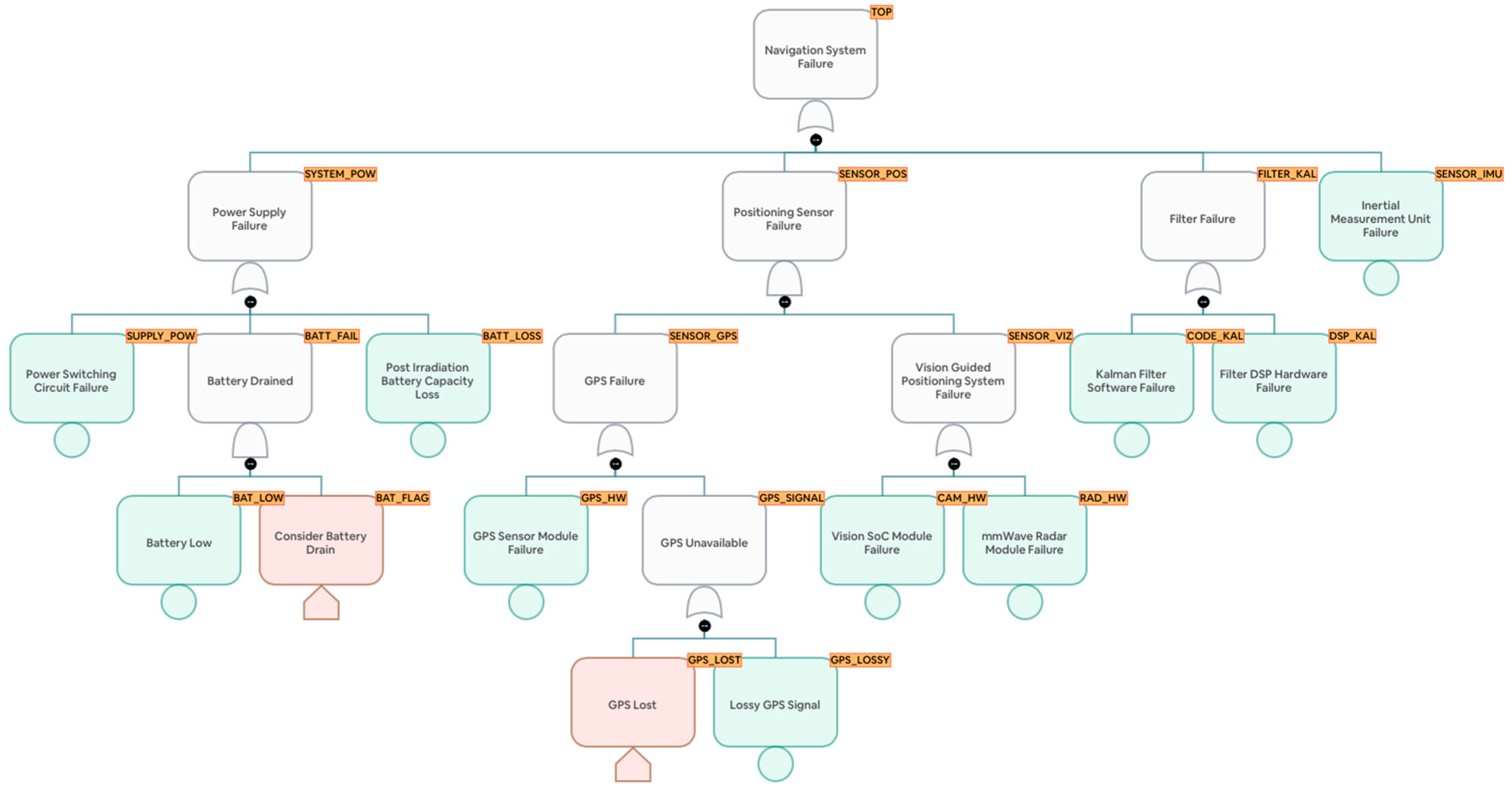
The fault tree for the drone's navigation system is constructed based on the potential failure modes of the system's components. It is depicted in
Figure 5. A fault tree is a graphical representation of the logical relationships between the failures, or "basic events", and the system-level failure, or "top event". The basic events are the lowest level failures that can occur in the system, while the top event is the failure of the entire system. The intermediate events represent the failure of subsystems or groups of components. The logical relationships between these events are represented by gates, which can be "AND" gates, "OR" gates, or more complex logical gates.
In the given fault tree, the top event is the failure of the drone's navigation system, represented by the gate "TOP". This event can occur due to the failure of the power system "SYSTEM_POW", the positioning sensors "SENSOR_POS", the Kalman filter "FILTER_KAL", or the inertial measurement unit sensors "SENSOR_IMU". The intermediate events are represented by the gates "SENSOR_POS", "FILTER_KAL", "SYSTEM_POW", "SENSOR_GPS", "SENSOR_VIZ", "BATT_FAIL", and "GPS_SIGNAL". Each of these gates represents a failure mode that can contribute to the top event. For example, the "SENSOR_POS" gate represents the failure of the positioning sensors, which can occur due to the failure of the GPS hardware "GPS_HW" or the visual sensors "SENSOR_VIZ".
The basic events are the lowest level failures that can occur in the system. These include the failure of the power supply "SUPPLY_POW", the battery running low “BAT_LOW", the loss of the battery "BATT_LOSS", the failure of the GPS hardware "GPS_HW", the loss of the GPS signal "GPS_LOSSY", the failure of the camera hardware "CAM_HW", the failure of the radiation sensor hardware "RAD_HW", the failure of the Kalman filter code "CODE_KAL", the failure of the Kalman filter DSP "DSP_KAL", and the failure of the IMU sensors "SENSOR_IMU". Failure rates for each hardware component and basic event are listed in
Table 6 and
Table 7. These rates were acquired from the Texas Instruments reliability database [
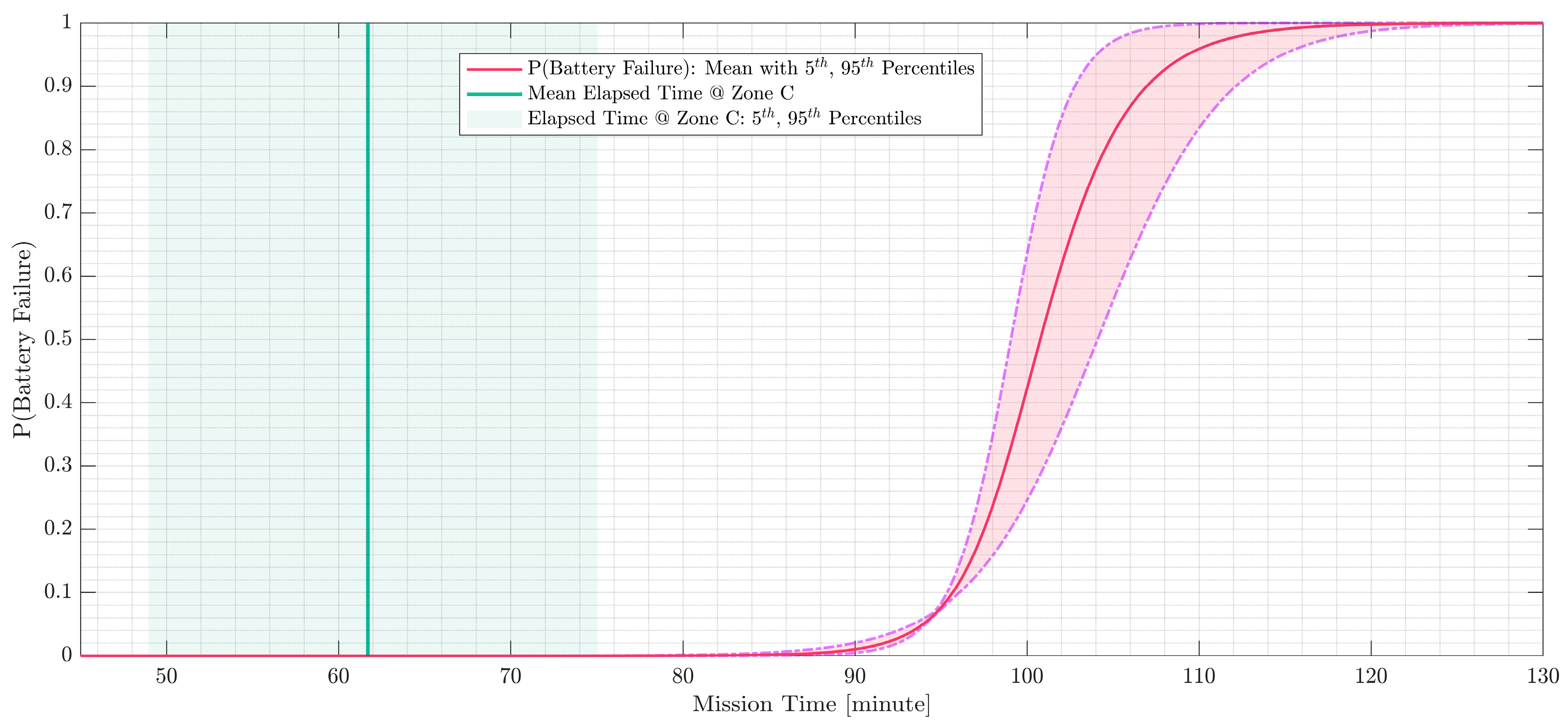
20]. They are used to calculate the probability of each basic event for the elapsed time at each radiation zone, which is used to calculate the probability of the intermediate and top events using the logical relationships defined by the gates. This allows for a quantitative assessment of the reliability of the drone's navigation system. Basic event BATT_LOW models battery drain, with the cumulative distribution function (CDF) plotted in
Figure 6. We observe that the battery has been chosen to last well beyond the mission time.
3.4. Modeling Kalman filter software failures using dual graph error propagation method (DEPM)
The Kalman filter software block is a critical component of the drone's navigation system. It processes the sensor data to estimate the drone's position and velocity, which are essential for controlling the drone's flight. The Kalman filter code is implemented on a digital signal processor (DSP), which is susceptible to radiation-induced single event upsets (SEUs) as well as TID effects. These events can cause bit flips in the processor's memory, leading to errors in the Kalman filter's calculations. In our model, we consider TID related permanent failures. A detailed analysis of transient and accumulated failures in DEPM can be found in [
21].
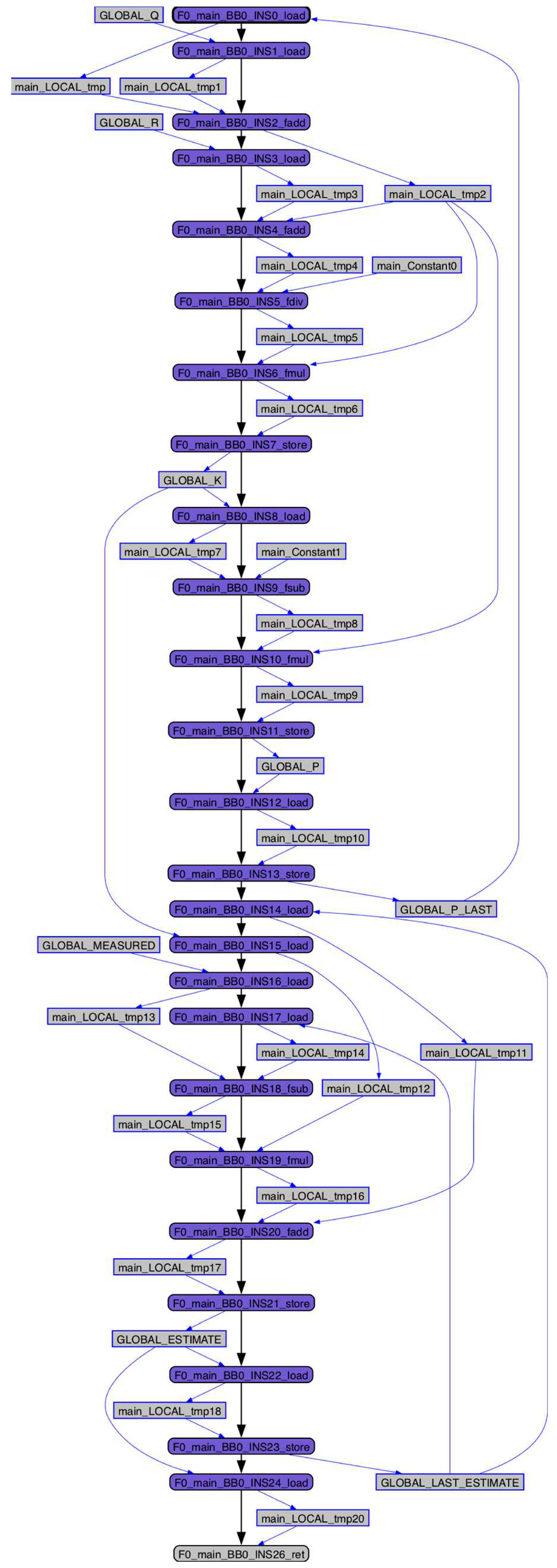
Failure analysis is performed by building a DEPM model from the Kalman filter assembly block, listed in
Table 8. The Kalman filter algorithm is a recursive algorithm used for estimating the evolving state of a system. It consists of two main steps: the prediction step and the update step. The prediction step predicts the next state of the system and the update step corrects the prediction based on the actual measurement.
In the DEPM, the assembly code is first translated into a control flow graph (CFG) and a data flow graph (DFG). The CFG represents the flow of control in the program, while the DFG represents the flow of data between operations. The DEPM then combines these two graphs into a dual-graph, which represents both the control flow and data flow in the program. The DEPM is used to analyze the propagation of accumulated errors in the software, caused by TID effects in the DSP hardware.
Figure 6 illustrates the DEPM for the Kalman filter assembly in
Table 8, compiled using the LLVMPars framework [
12].
3.5. Modeling Total Ionizing Dose limits for Electronic Hardware
TID is a measure of the amount of radiation absorbed by electronic components. Excessive TID can cause degradation or failure of these components, leading to mission failure. In order to assess the survivability of the drone's electronic hardware in each radiation zone, the TID limits for each component need to be determined. The TID limits for electronic components are typically provided by manufacturers and are based on the radiation hardness of the components [
22]. These limits specify the maximum TID that a component can withstand without experiencing significant degradation or failure. It is important to note that these limits may vary depending on the specific component and its application. For the purpose of this demonstration case, we assume that the drone's electronic hardware consists of off-the-shelf components from a reputable manufacturer. The TID limits for these components are obtained from the manufacturer's specifications or empirical tests and are listed in
Table 9.
Using the TID limits from
Table 9, the probability of failure for each component can be calculated based on the total received dose. This probability is then used to determine the likelihood of component failure in each radiation zone. For example, let's consider the COTS Inertial Measurement Unit (IMU) component. The TID limit for the IMU is in the range of
[
23]. Based on the total received dose in each radiation zone, the probability of exceeding the TID limit for the IMU can be calculated. If the probability of exceeding the TID limit is below this threshold, the IMU is considered to have survived in that radiation zone. Otherwise, the IMU is considered to have failed. Similarly, the probability of failure can be calculated for other components such as the power switching circuit, lithium-ion battery [
24], GPS sensor module, vision SoC module, mmWave radar module, and filter DSP hardware [
25,
26].
By assessing the probability of failure for each component in each radiation zone, the most vulnerable components can be identified. These components can then be targeted for radiation hardening measures, such as shielding or the use of radiation-hardened components, to improve their survivability in nuclear-contaminated environments. In the next section, we present the results of this analysis, and re-run it after radiation hardening the components that contribute most to navigation system failure and LOM.
4. Results and Discussion
The results of the D-PRA for the drone's navigation system are presented in this section. The D-PRA was performed using the OpenPRA framework, which integrates the event tree/fault tree approach with DEPM to model the propagation of errors in the drone's navigation system. The results are presented in terms of the LOM likelihood in each radiation zone, as well as the most vulnerable components that contribute to LOM.
4.1. Probability of Loss of Mission (LOM) using Commercial-Off-The-Shelf (COTS) Components
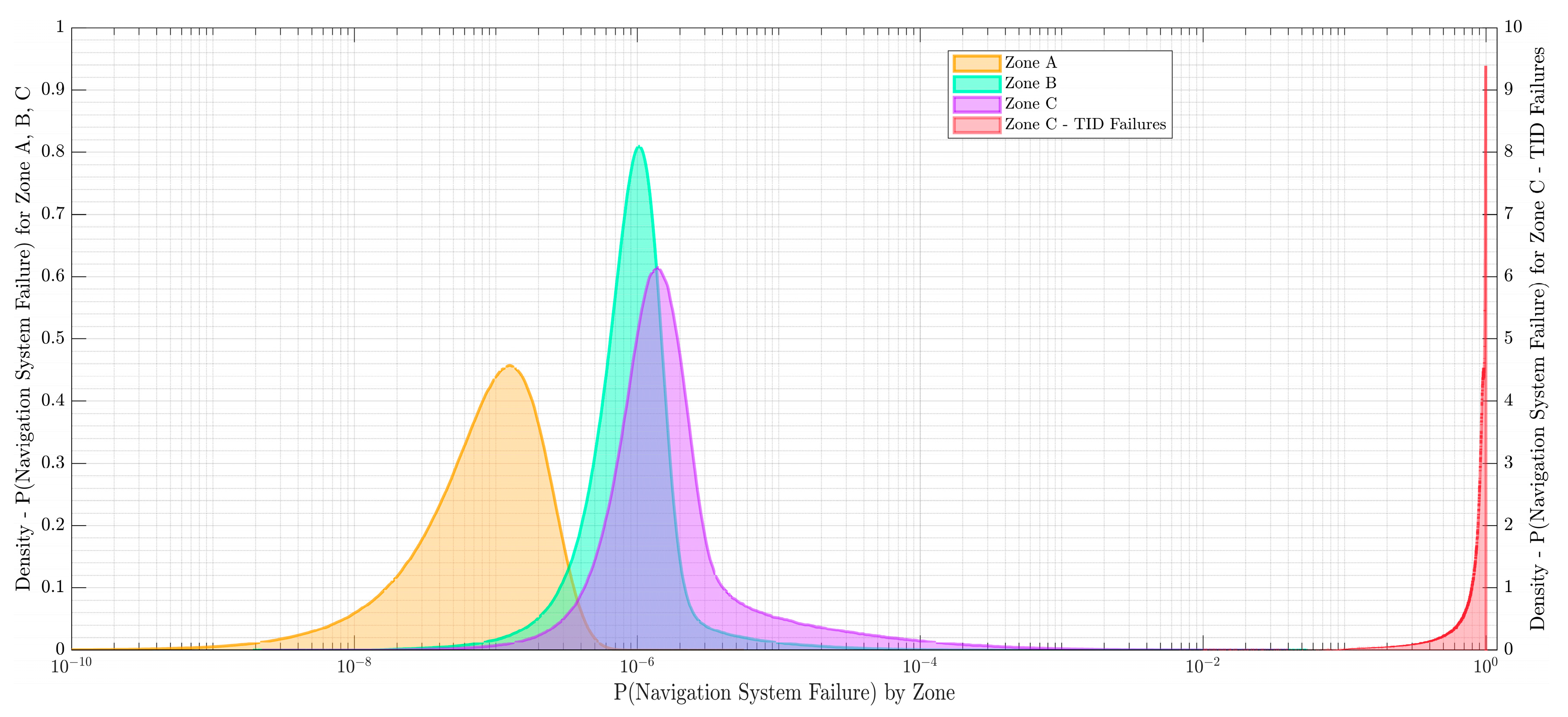
The probability of LOM in each radiation zone is calculated based on the failure probabilities of the components in the drone's navigation system. The results are plotted in
Figure 8 and listed in
Table 10. As expected, the probability of LOM increases with the radiation level, with the highest probability in Zone C, the highest radiation zone. This is due to the higher TID received by the components in this zone, which increases the likelihood of component failure.
Table 10 presents the probability of LOM due to the failure of the drone's navigation system in each radiation zone (A, B, and C). The sampled probabilities are parametrized using a log-normal distribution (LN), with the mean (m) and error factor (EF) parameters provided. The probability of LOM is low and dependent on non-radiation related phenomena for all parts in Zones A and B, and most parts of Zone C. This suggests that the drone's navigation system is relatively reliable in low radiation environments, averaging about one LOM per ten thousand missions. However, the probability of LOM increases significantly in Zone C. This is due to the higher TID received by the components in this zone, which increases the likelihood of component failure. This is a significant concern, as it suggests that the drone may not be able to complete its mission in high radiation environments. This could have serious consequences for SAR missions, as it could prevent the drone from reaching survivors or accurately assessing the extent of the damage.
In terms of mission success, the results indicate a relatively low probability. This suggests that the current design of the drone's navigation system may not be suitable for SAR missions in nuclear-contaminated environments. Therefore, improvements to the design, such as the use of radiation-hardened components or shielding, may be necessary to increase the probability of mission success.
4.2. Selective Radiation Hardening using Mission Success Criteria
With the objective of improving the unacceptably low likelihood of mission success, we propose a strategy to selectively harden the most vulnerable components in the navigation system. We begin by choosing a vulnerable component and assign a wide distribution for its TID limit. For instance, we choose the DSP and assign its TID limit as
. Here,
is a loguniform distribution, and much wider than the nominal value specified in
Table 9. Next, we invert the probability of mission success, making it conditional on the event
, and accept
values only when LOM does not occur.
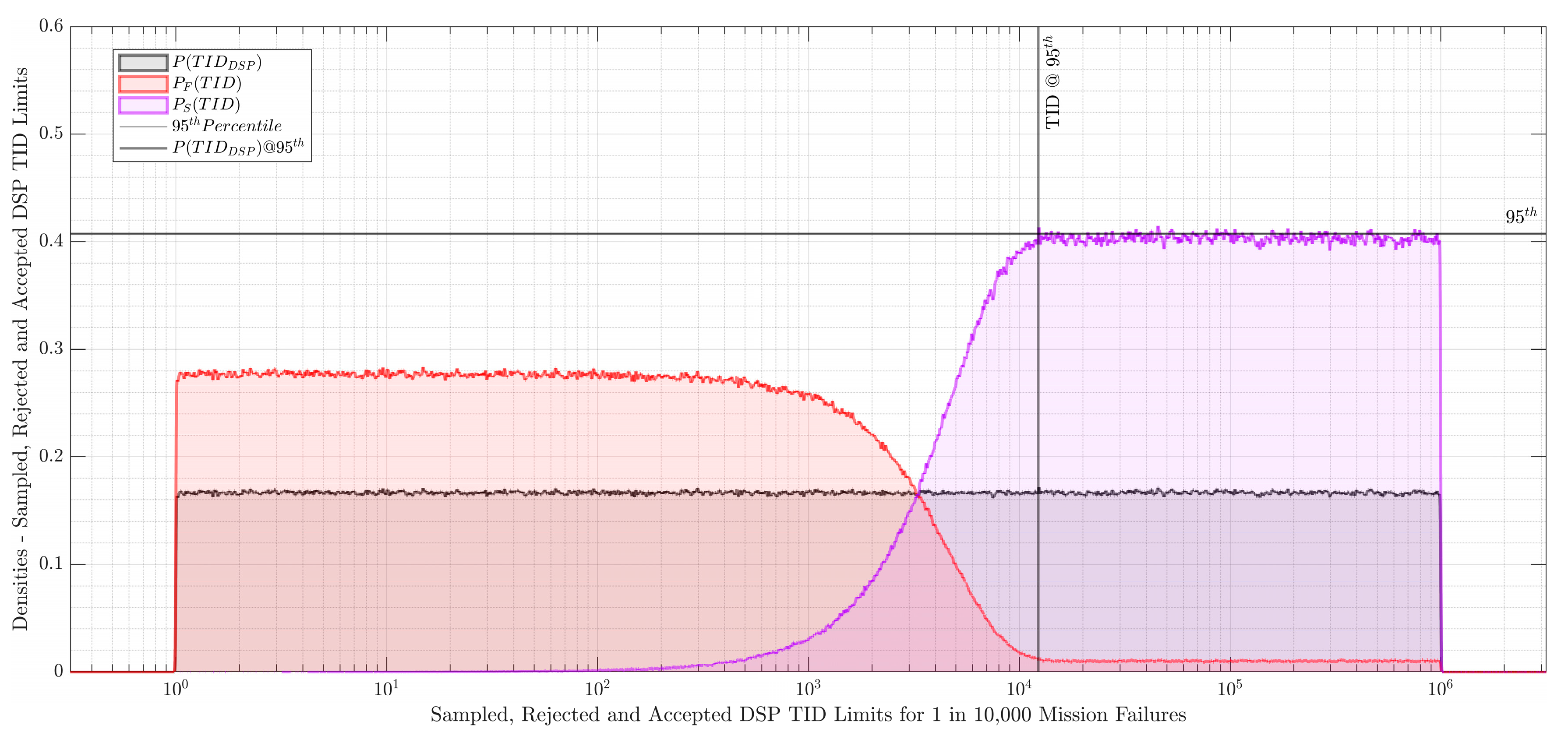
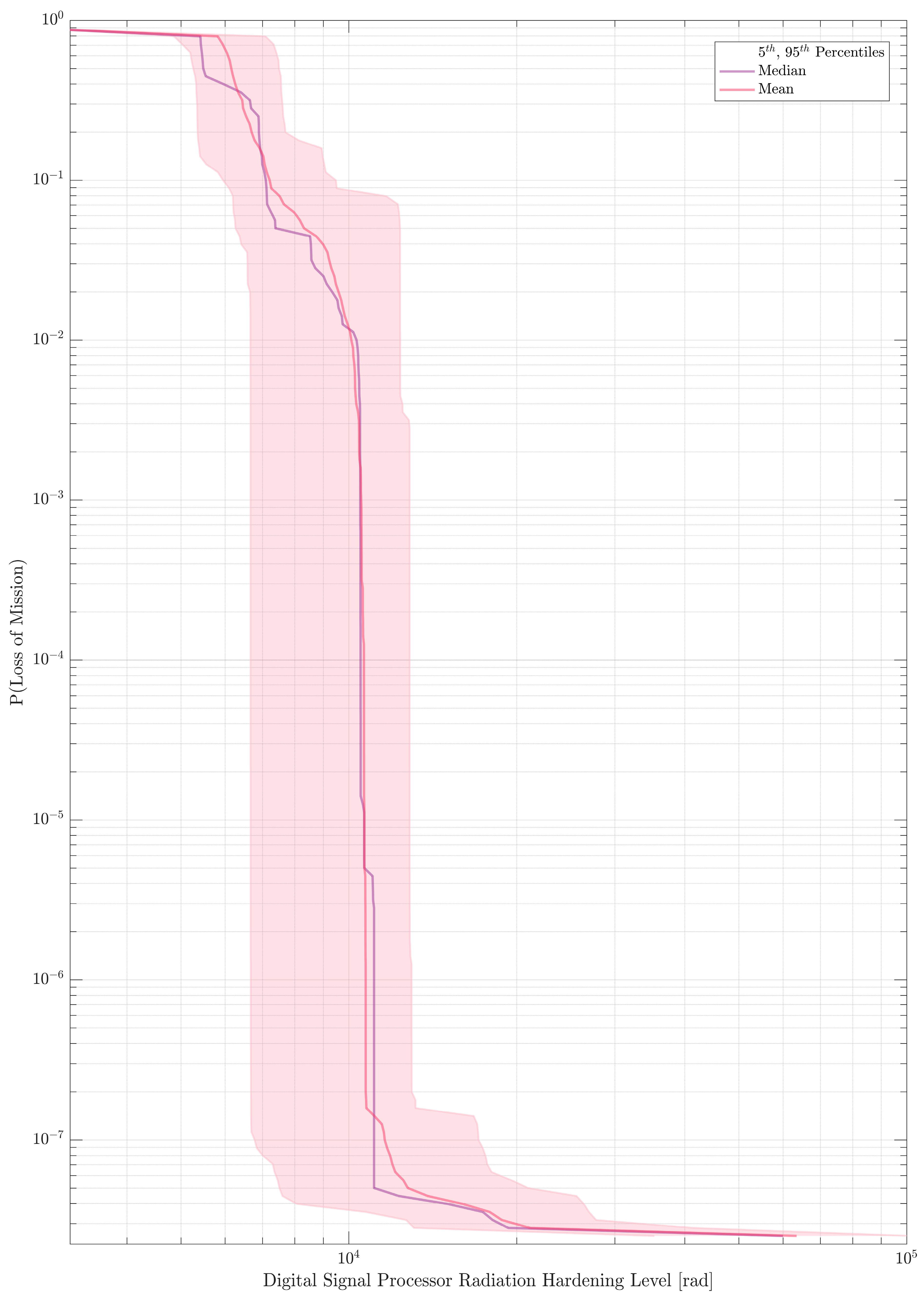
Figure 9 plots the kernel density estimates for the sampled, accepted and rejected DSP TID limit ranges at the 95th percentile for 1 in 10,000 mission failures. By extension, sampling over a range of expected mission failure rates, we can construct a radiation hardening vs mission failure curve. This curve has been illustrated in
Figure 10.
The results of the analysis allow us to choose a radiation hardening limit based on target mission success criteria.
5. Conclusion
This paper presented a dynamic probabilistic risk assessment (D-PRA) approach for assessing the survivability of commercial off-the-shelf (COTS) drones in nuclear-contaminated search and rescue (SAR) missions. The D-PRA approach integrates the traditional event tree/fault tree approach with the dual-graph error propagation method (DEPM) to model the propagation of errors in the drone's navigation system. The results of the D-PRA demonstrated the usefulness of the proposed approach in identifying the most vulnerable components for radiation hardening (RAD-HARD) improvements.
The results of the D-PRA showed that the probability of loss of mission (LOM) increases with the radiation level, with the highest probability in the high radiation zone. This is due to the higher total ionizing dose (TID) received by the components in this zone, which increases the likelihood of component failure. The results also showed that the current design of the drone's navigation system may not be suitable for SAR missions in nuclear-contaminated environments, suggesting that improvements to the design, such as the use of RAD-HARD components or shielding, may be necessary to increase the probability of mission success.
Future work will focus on extending the D-PRA approach to include other potential failure modes, such as single-event effects (SEEs) and displacement damage, which were not considered in this study. Additionally, the impact of weather conditions and terrain on the drone's ability to navigate each radiation zone will be considered. Finally, the potential for human error in drone operation, which can significantly contribute to mission failure, will be incorporated into the model.
In conclusion, the proposed D-PRA approach provides a systematic and comprehensive framework for assessing the survivability of COTS drones in nuclear SAR missions. By identifying the most vulnerable components for RAD-HARD improvements, the approach can help to improve the reliability and safety of these drones, thereby enhancing their effectiveness in SAR missions in nuclear-contaminated environments.
Author Contributions
Conceptualization, A.E. and M.A.D.; methodology, A.E. and M.A.D.; verification, A.E. and M.A.D; formal analysis, A.E.; investigation, A.E. and M.A.D; resources, A.E. and M.A.D; data curation, A.E.; writing—original draft preparation, A.E.; writing—review and editing, M.A.D; visualization, A.E.; supervision, M.A.D; project administration, M.A.D; funding acquisition, M.A.D. All authors have read and agreed to the published version of the manuscript.
Funding
This research received no external funding.
Conflicts of Interest
The authors declare no conflict of interest.
References
- M. I. Ahmad, M. H. Ab. Rahim, R. Nordin, F. Mohamed, A. Abu-Samah, and N. F. Abdullah, “Ionizing Radiation Monitoring Technology at the Verge of Internet of Things,” Sensors, vol. 21, no. 22, p. 7629, Nov. 2021. [CrossRef]
- L. R. Pinto et al., “Radiological Scouting, Monitoring and Inspection Using Drones,” Sensors, vol. 21, no. 9, p. 3143, Apr. 2021. [CrossRef]
- B. J. Garrick, Quantifying and Controlling Catastrophic Risks. Academic Press, 2008.
- W.E. Vesely,F.F. Goldberg,N.H. Roberts,D.F. Haasl, “NUREG-0492, ‘Fault Tree Handbook’.” Jan. 1981. [Online]. Available: https://drum.lib.umd.edu/handle/1903/7729. 1903.
- S. A. Kripke, “Semantical Considerations on Modal Logic,” Acta Philos. Fenn., vol. 16, pp. 83–94, 1963, [Online]. Available: http://saulkripkecenter.org/wp-content/uploads/2019/03/Semantical-Considerations-on-Modal-Logic-PUBLIC.pdf.
- M. Kwiatkowska, G. M. Kwiatkowska, G. Norman, and D. Parker, “Stochastic Model Checking,” in Formal Methods for Performance Evaluation, M. Bernardo and J. Hillston, Eds., in Lecture Notes in Computer Science, vol. 4486. Berlin, Heidelberg: Springer Berlin Heidelberg, 2007, pp. 220–270. https://doi.org/10.1007/978-3-540-72522-0_6. [CrossRef]
- C. Baier and J.-P. Katoen, Principles of model checking. Cambridge, Mass: The MIT Press, 2008.
- K. Schneider, Verification of reactive systems: formal methods and algorithms. in Texts in theoretical computer science. Berlin ; New York: Springer-Verlag, 2004
.
- M. O. Rabin and D. Scott, “Finite Automata and Their Decision Problems,” IBM J. Res. Dev., vol. 3, no. 2, pp. 114–125, Apr. 1959. [CrossRef]
- M. A. Diaconeasa and A. Mosleh, “The ADS-IDAC Dynamic Platform with Dynamically Linked System Fault Trees,” Philadelphia, PA, 2017.
- Morozov and K. Janschek, “Dual Graph Error Propagation Model for Mechatronic System Analysis,” IFAC Proc. Vol., vol. 44, no. 1, pp. 9893–9898, Jan. 2011. [CrossRef]
- V. Vidineev, N. Yusupova, K. Ding, A. Morozov, and K. Janschek, “Improved stochastic control flow model for LLVM-based software reliability analysis,” Ind. 40, vol. 3, no. 4, pp. 172–174, 2018, Accessed: Aug. 02, 2022. [Online]. Available: https://stumejournals.com/journals/i4/2018/4/172.
- K. Ding, S. Ding, A. Morozov, T. Fabarisov, and K. Janschek, “On-Line Error Detection and Mitigation for Time-Series Data of Cyber-Physical Systems using Deep Learning Based Methods,” in 2019 15th European Dependable Computing Conference (EDCC), Naples, Italy: IEEE, Sep. 2019, pp. 7–14. [CrossRef]
- J. Marques-silva, “Practical applications of boolean satisfiability,” in In Workshop on Discrete Event Systems (WODES, IEEE Press, 2008.
- R. E. Bryant and M. J. Heule, “Generating extended resolution proofs with a BDD-based SAT solver,” in International Conference on Tools and Algorithms for the Construction and Analysis of Systems, Springer, 2021, pp. 76–93.
- K. Vetter, “The Institute of Resilient Communities,” in Resilience: A New Paradigm of Nuclear Safety, J. Ahn, F. Guarnieri, and K. Furuta, Eds., Cham: Springer International Publishing, 2017, pp. 207–218. [CrossRef]
- K. Vetter, “Multi-sensor radiation detection, imaging, and fusion,” Nucl. Instrum. Methods Phys. Res. Sect. Accel. Spectrometers Detect. Assoc. Equip., vol. 805, pp. 127–134, Jan. 2016. [CrossRef]
- G.U. Medvedevs, “JPRS Report, Soviet Union: Economic Affairs (‘Chernobyl Notebook’),” Soviet Union: Economic Affairs, JPRS-UEA-89-034, Oct. 1989. Accessed: Jun. 19, 2023. [Online]. Available: https://apps.dtic.mil/sti/pdfs/ADA335076.pdf.
- OpenPRA Community, “OpenPRA Initiative,” Apr. 01, 2019. https://openpra.org/ (accessed Jan. 17, 2022).
- “Texas Instruments - Reliability Testing,” Texas Instruments Quality & Reliability. https://www.ti.com/support-quality/reliability/reliability-testing.html (accessed Jan. 10, 2022).
- Earthperson, C. M. Otani, D. Nevius, S. R. Prescott, and M. A. Diaconeasa, “A combined strategy for dynamic probabilistic risk assessment of fission battery designs using EMRALD and DEPM,” Prog. Nucl. Energy, vol. 160, p. 104673, Jun. 2023. [CrossRef]
- “GSFC Radiation Data Base.” https://radhome.gsfc.nasa.gov/radhome/RadDataBase/RadDataBase.html (accessed Jun. 16, 2023).
- G. Bazzano et al., “Radiation testing of a commercial 6-axis MEMS inertial navigation unit at ENEA Frascati proton linear accelerator,” Adv. Space Res., vol. 67, no. 4, pp. 1379–1391, Feb. 2021. [CrossRef]
- J. Qiu et al., “Effects of neutron and gamma radiation on lithium-ion batteries,” Nucl. Instrum. Methods Phys. Res. Sect. B Beam Interact. Mater. At., vol. 345, pp. 27–32, Feb. 2015. [CrossRef]
- M. Markgraf and O. Montenbruck, “Total Ionizing Dose Testing of the Orion and Phoenix GPS Receivers,” German Space Operations Center (GSOC), TN 04-01, Feb. 2004. [Online]. Available: https://www.dlr.de/rb/Portaldata/38/Resources/dokumente/GSOC_dokumente/RB-RFT/TN_0401.pdf.
- N. Rezzak, J.-J. Wang, C.-K. Huang, V. Nguyen, and G. Bakker, “Total Ionizing Dose Characterization of 65 nm Flash-Based FPGA,” in 2014 IEEE Radiation Effects Data Workshop (REDW), Paris, France: IEEE, Jul. 2014, pp. 1–5.
| 1 |
If the source set equals the domain, is left-total.
|
| 2 |
– Normal distribution, truncated to represent a realistic and physically meaninginful sampling space. For example, time cannot be negative.
|
| 3 |
– Loguniform distribution with and
|
Figure 1.
State transitions within a three-state system, initialized as nominal. (left) temporal, (right) state machine.
Figure 1.
State transitions within a three-state system, initialized as nominal. (left) temporal, (right) state machine.
Figure 2.
Example DEPM with a legend.
Figure 2.
Example DEPM with a legend.
Figure 3.
Kernel Density Estimates for Total Received Dose by Zone.
Figure 3.
Kernel Density Estimates for Total Received Dose by Zone.
Figure 4.
Event tree description of navigation system availability for radiation zones A,B, and C.
Figure 4.
Event tree description of navigation system availability for radiation zones A,B, and C.
Figure 5.
Navigation system failure fault tree.
Figure 5.
Navigation system failure fault tree.
Figure 6.
Cumulative Distribution Function for Probability of Battery Drain for a range of mission times.
Figure 6.
Cumulative Distribution Function for Probability of Battery Drain for a range of mission times.
Figure 7.
Dual Graph Error Propagation (DEPM) representation of assembly for a single variable Kalman filter.
Figure 7.
Dual Graph Error Propagation (DEPM) representation of assembly for a single variable Kalman filter.
Figure 8.
Density estimates of COTS Navigation System Failure probabilities by Zone and TID effects.
Figure 8.
Density estimates of COTS Navigation System Failure probabilities by Zone and TID effects.
Figure 9.
Digital Signal Processor Total Ionizing Dose Limits for 1 in 10,000 Mission Failures.
Figure 9.
Digital Signal Processor Total Ionizing Dose Limits for 1 in 10,000 Mission Failures.
Figure 10.
Radiation Hardening Targets vs Likelihood of Mission Failure.
Figure 10.
Radiation Hardening Targets vs Likelihood of Mission Failure.
Table 1.
3-tuple Kripke terms for a 3-state transition system.
Table 1.
3-tuple Kripke terms for a 3-state transition system.
| Term |
Definition |
Description |
|
|
A set of possible states |
|
|
The initial state, which is nominal |
|
|
is fully-connected. |
Table 2.
State transition definitions for three state model referenced in
Figure 1.
Table 2.
State transition definitions for three state model referenced in
Figure 1.
| Regular Expression |
Term |
Description |
| A*
|
Ideal/Perfect System |
No errors, faults, or failures occur. |
| B |
Fault |
A fault is a weakness that can potentially lead to errors. |
| DF*|C+
|
Error Propagation |
Move from an initial error state leads to a subsequent one. |
| D|I |
Failure |
System fails from either a degraded or a nominal state. |
| E|G|H |
Recoverable System |
Move from higher to lower degradation. |
| B(C*|E) |
Fault Tolerant |
Avoid transition to failure, given a fault. |
| A*|(B(C*|E)) |
Failure Avoidant |
No failures occur. |
| G|H |
Resilient System |
Recover from a failure, either fully or partially. |
| B(C*|D(F*|G))|(I(F*|G)) |
Irrecoverable System |
Neither completely fails, nor returns to nominal. |
| F+
|
Permanently Failed |
System remains irrecoverable forever. |
Table 3.
Definitions for terms in Dual-Graph Error Propagation Model (DEPM).
Table 3.
Definitions for terms in Dual-Graph Error Propagation Model (DEPM).
| Term |
Definition |
|
A set of elements, always non-empty. |
|
A set of optional data terms. |
|
An edge-list representing control flows. |
|
An edge-list representing data flows. |
|
. |
Table 4.
Conditional Logic Table for example DEPM in
Figure 2.
Table 4.
Conditional Logic Table for example DEPM in
Figure 2.
| Element |
Conditional Expressions |
| A |
always:
with P(0.8): DATA VARIABLE 1, DATA VARIABLE 2 = error
with P(0.2): DATA VARIABLE 1, DATA VARIABLE 2 = ok |
| B |
if DATA VARIABLE 1 = error, then:
with P(0.9): DATA VARIABLE 2 = ok
with P(0.1): DATA VARIABLE 2 = errorelse:
with P(1.0): DATA VARIABLE 2 = ok |
| C |
if DATA VARIABLE 2 & DATA VARIABLE 3 = ok, then:
with P(1.0): DATA VARIABLE 4 = okelse:
with P(0.2): DATA VARIABLE 4 = ok
with P(0.8): DATA VARIABLE 4 = error |
Table 5.
Ambient radiation dose rates for radiation zones A, B, C.
Table 5.
Ambient radiation dose rates for radiation zones A, B, C.
| Zone |
Dose Rate[rad/hour] |
Elapsed Time[minute] |
Total Received Dose[rad] |
| A |
|
|
|
| B |
|
|
|
| C |
|
|
|
Table 6.
Manufacturer (Texas Instruments) provided failure rates for generic drone hardware components.
Table 6.
Manufacturer (Texas Instruments) provided failure rates for generic drone hardware components.
| Basic Event |
Part Number |
Component Type |
Derated Failure Rate] |
| SENSOR_IMU |
TI-MSP430 Series |
MEMS IMU |
|
| CAM_HW |
TI-TDA4AL-Q1 |
Vision SoC + DSP |
|
| RAD_HW |
TI-IWR1642AQAGABL |
mmWave Radar + DSP |
|
| DSP_KAL |
TI-TMS320C6678 |
Kalman Filter DSP |
|
Table 7.
Basic event probabilities for drone navigation system failure fault tree.
Table 7.
Basic event probabilities for drone navigation system failure fault tree.
| Basic Event |
Basic Event Description |
Failure Rate] |
| SENSOR_IMU |
Inertial Measurement Unit Failure |
|
| CAM_HW |
Vision System-on-Chip Module Failure |
|
| RAD_HW |
mmWave Radar Module Failure |
|
| DSP_KAL |
Filter DSP Hardware Failure |
|
| CODE_KAL |
Kalman Filter Software Failure |
DEPM, see section on Page 12 |
| GPS_HW |
GPS Sensor Module Failure |
|
| GPS_LOSSY |
Lossy GPS Signal |
|
| SUPPLY_POW |
Switching Power Supply Circuit Failure |
|
| BATT_LOW |
Battery Low |
Time dependent, see Figure 6
|
| BATT_LOSS |
Post Irradiation Battery Capacity Loss |
P = 1 as TID approaches TID limit |
Table 8.
Assembler code for single variable Kalman filter algorithm.
Table 8.
Assembler code for single variable Kalman filter algorithm.
/***
Kalman Filter (Single Variable)
* Assume the input is in register R0
* Assume the initial state estimate is in register R1
* Assume the initial error covariance is in register R2
* Assume the process noise variance is in register R3
* Assume the measurement noise variance is in register R4
**/
Initialization
1. MOV R5, R1 // R5 = State estimate (copy of initial state estimate)
2. MOV R6, R2 // R6 = Error covariance (copy of initial error covariance)
LOOP:
Prediction step
4. MOV R7, R5 // R7 = Predicted state estimate (copy of state estimate)
5. ADD R5, R7 // R5 = State estimate = State estimate + Predicted state estimate
6. MOV R8, R6 // R8 = Predicted error covariance (copy of error covariance)
7. ADD R8, R3 // R8 = Predicted error covariance + Process noise variance
8.MOV R6, R8 // R6 = Error covariance = Predicted error covariance + Process noise variance
Update step
9. MOV R9, R6 // R9 = Error covariance (copy of error covariance)
10. ADD R9, R4 // R9 = Error covariance + Measurement noise variance
11. MOV R10, R9 // R10 = Temporary variable for division
12. DIV R8, R10 // R8 = Kalman gain = Error covariance / (Error covariance + Measurement noise variance)
13. MOV R11, R0 // R11 = Measurement
14. SUB R11, R7 // R11 = Measurement - Predicted state estimate
15. MUL R11, R8 // R11 = Innovation = (Measurement - Predicted state estimate) * Kalman gain
16. ADD R5, R11 // R5 = State estimate = State estimate + Innovation
17. MOV R12, R8 // R12 = Kalman gain (copy of Kalman gain)
18. SUB R12, R8 // R12 = 1 - Kalman gain
19. MUL R6, R12 // R6 = Error covariance = Error covariance * (1 - Kalman gain)
// Continue the loop or terminate
|
Table 9.
Total Ionizing Dose (TID) limits, COTS Components.
Table 9.
Total Ionizing Dose (TID) limits, COTS Components.
| Component |
Commercial Off The Shelf(COTS) |
| Inertial Measurement Unit |
|
| Power Switching Circuit |
|
| Lithium Ion Battery |
|
| GPS Sensor Module |
|
| Vision SoC Module |
|
| mmWave Radar Module |
|
| Filter DSP Hardware |
|
Table 10.
Probability of Loss of Mission (LOM) due to COTS drone Navigation System Failure.
Table 10.
Probability of Loss of Mission (LOM) due to COTS drone Navigation System Failure.
| End State |
End State Description |
P(End State) |
|
Loss of Mission in Zone A |
|
|
Loss of Mission in Zone B |
|
|
Loss of Mission in Zone C |
|
|
Mission Success |
|
|
Disclaimer/Publisher’s Note: The statements, opinions and data contained in all publications are solely those of the individual author(s) and contributor(s) and not of MDPI and/or the editor(s). MDPI and/or the editor(s) disclaim responsibility for any injury to people or property resulting from any ideas, methods, instructions or products referred to in the content. |
© 2023 by the authors. Licensee MDPI, Basel, Switzerland. This article is an open access article distributed under the terms and conditions of the Creative Commons Attribution (CC BY) license (https://creativecommons.org/licenses/by/4.0/).
