Submitted:
06 July 2023
Posted:
10 July 2023
You are already at the latest version
Abstract
Keywords:
1. Introduction
2. Working Mechanism of Ternary Organic Solar Cells
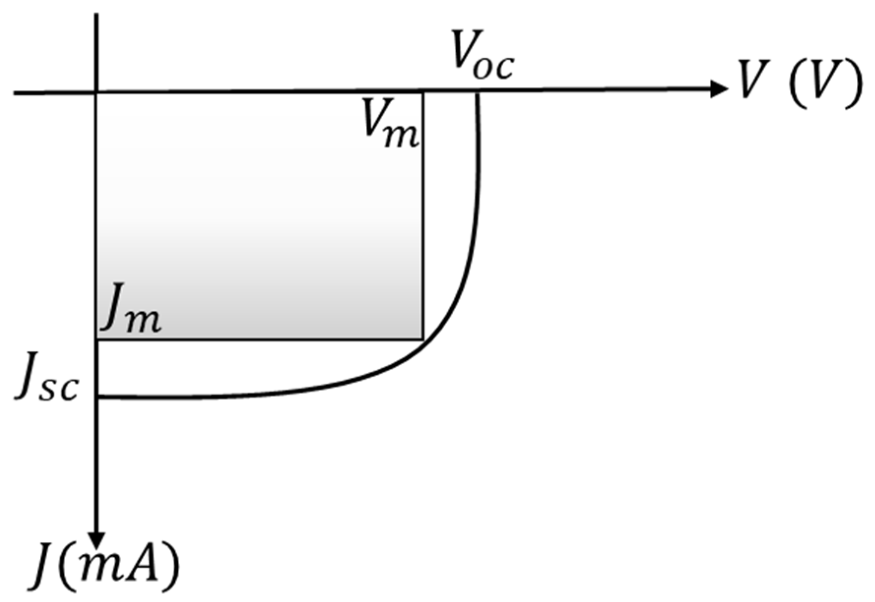
3. Solar Cell Parameters
4. Photoactive Layer Characterization
4.1. Photophysical Characterization
4.2. Energy gaps and transition types
5. Materials for Semi-Transparent Organic Photoactive Layer
5.1. Dye Materials for Semitransparent Solar Cells
5.2. Non-Fullerene Acceptors
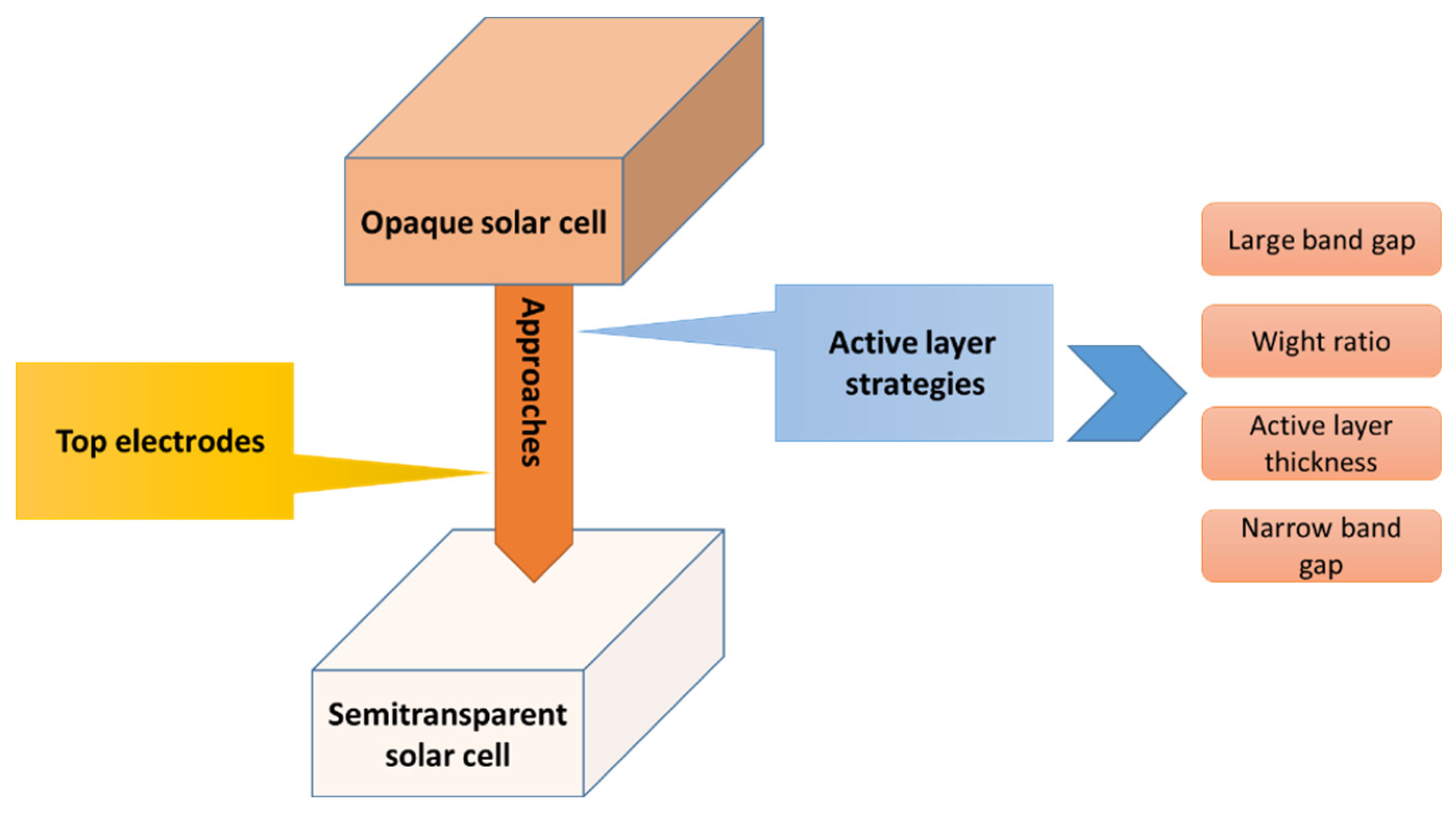
6. Approaches to Improve Semi-Transparent OSCs
6.1. Active Layer Strategies
6.2. Transparent Top Electrodes
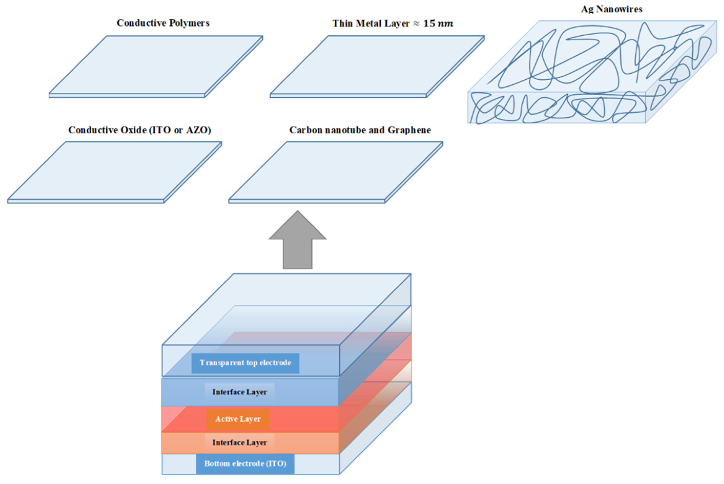
7. Conclusions
Author Contributions
Funding
Institutional Review Board Statement
Data Availability Statement
Acknowledgments
Conflicts of Interest
References
- Tsai, C.-H.; Lin, C.-M.; Kuei, C.-H. Investigation of the Effects of Various Organic Solvents on the PCBM Electron Transport Layer of Perovskite Solar Cells. Coatings 2020, 10, 237. [Google Scholar] [CrossRef]
- Goetzberger, A.; Hebling, C.; Schock, H.-W. Photovoltaic materials, history, status and outlook. Materials Science and Engineering: R: Reports 2003, 40, 1–46. [Google Scholar] [CrossRef]
- Askari, M.; Mirzaei Mahmoud Abadi, V.; Mirhabibi, M. Types of Solar Cells and Application. American Journal of Optics and Photonics 2015, 3, 2015. [Google Scholar] [CrossRef]
- Andreani, L.C.; Bozzola, A.; Kowalczewski, P.; Liscidini, M.; Redorici, L. Silicon solar cells: toward the efficiency limits. Advances in Physics: X 2019, 4, 1548305. [Google Scholar] [CrossRef]
- Bhattacharya, S.; John, S. Beyond 30% Conversion Efficiency in Silicon Solar Cells: A Numerical Demonstration. Scientific Reports 2019, 9, 12482. [Google Scholar] [CrossRef] [PubMed]
- Lee, C.; Lee, S.; Kim, G.U.; Lee, W.; Kim, B.J. Recent Advances, Design Guidelines, and Prospects of All-Polymer Solar Cells. Chem Rev 2019, 119, 8028–8086. [Google Scholar] [CrossRef]
- Wang, G.; Melkonyan, F.S.; Facchetti, A.; Marks, T.J. All-Polymer Solar Cells: Recent Progress, Challenges, and Prospects. Angewandte Chemie International Edition 2019, 58, 4129–4142. [Google Scholar] [CrossRef]
- Guguloth, L.; Singh, K.; Reddy Channu, V.S.; Kumari, K. Improved performance of ternary blend polymer solar cells via work function tuning and suppressed interface recombination using hybrid PEDOT:PSS-graphene oxide hole transport layer. Applied Surface Science 2021, 540, 148266. [Google Scholar] [CrossRef]
- Chang, M.; Meng, L.; Wang, Y.; Ke, X.; Yi, Y.-Q.-Q.; Zheng, N.; Zheng, W.; Xie, Z.; Zhang, M.; Yi, Y.; et al. Achieving an Efficient and Stable Morphology in Organic Solar Cells Via Fine-Tuning the Side Chains of Small-Molecule Acceptors. Chemistry of Materials 2020, 32, 2593–2604. [Google Scholar] [CrossRef]
- Lin, Y.; Firdaus, Y.; Nugraha, M.I.; Liu, F.; Karuthedath, S.; Emwas, A.-H.; Zhang, W.; Seitkhan, A.; Neophytou, M.; Faber, H.; et al. 17.1% Efficient Single-Junction Organic Solar Cells Enabled by n-Type Doping of the Bulk-Heterojunction. Advanced Science 2020, 7, 1903419. [Google Scholar] [CrossRef]
- Liu, Z.; Wang, N. Efficient ternary all small molecule organic photovoltaics with NC70BA as third component materials. Dyes and Pigments 2021, 187, 109111. [Google Scholar] [CrossRef]
- Khlyabich, P.P.; Rudenko, A.E.; Thompson, B.C.; Loo, Y.-L. Structural Origins for Tunable Open-Circuit Voltage in Ternary-Blend Organic Solar Cells. Advanced Functional Materials 2015, 25, 5557–5563. [Google Scholar] [CrossRef]
- Chen, W.; Jiang, H.; Huang, G.; Zhang, J.; Cai, M.; Wan, X.; Yang, R. High-Efficiency Ternary Polymer Solar Cells Based on Intense FRET Energy Transfer Process. Solar RRL 2018, 2, 1800101. [Google Scholar] [CrossRef]
- Fan, B.; Zhong, W.; Jiang, X.-F.; Yin, Q.; Ying, L.; Huang, F.; Cao, Y. Improved Performance of Ternary Polymer Solar Cells Based on A Nonfullerene Electron Cascade Acceptor. Advanced Energy Materials 2017, 7, 1602127. [Google Scholar] [CrossRef]
- Sun, C.; Xia, R.; Shi, H.; Yao, H.; Liu, X.; Hou, J.; Huang, F.; Yip, H.-L.; Cao, Y. Heat-insulating multifunctional semitransparent polymer solar cells. Joule 2018, 2, 1816–1826. [Google Scholar] [CrossRef]
- Wang, D.; Liu, H.; Li, Y.; Zhou, G.; Zhan, L.; Zhu, H.; Lu, X.; Chen, H.; Li, C.-Z. High-performance and eco-friendly semitransparent organic solar cells for greenhouse applications. Joule 2021, 5, 945–957. [Google Scholar] [CrossRef]
- Li, Y.; Huang, X.; Sheriff, H.K.M.; Forrest, S.R. Semitransparent organic photovoltaics for building-integrated photovoltaic applications. Nature Reviews Materials 2023, 8, 186–201. [Google Scholar] [CrossRef]
- Zhao, N.; Zhen, T.; Wu, Y.; Wei, B.; Liao, Y.; Liu, Y. Efficient Semitransparent Organic Solar Cells Enabled by Ag Grid Electrodes and Optical Coupling Layers. Nanomaterials 2023, 13, 1308. [Google Scholar] [CrossRef]
- Adil, M.A.; Iqbal, M.J.; Zhang, J.; Wei, Z. Unconventional third components for ternary organic solar cells. Materials Today Energy 2021, 21, 100728. [Google Scholar] [CrossRef]
- Yu, R.; Yao, H.; Hou, J. Recent progress in ternary organic solar cells based on nonfullerene acceptors. Advanced Energy Materials 2018, 8, 1702814. [Google Scholar] [CrossRef]
- Ameri, T.; Khoram, P.; Min, J.; Brabec, C.J. Organic ternary solar cells: a review. Advanced Materials 2013, 25, 4245–4266. [Google Scholar] [CrossRef] [PubMed]
- An, Q.; Zhang, F.; Zhang, J.; Tang, W.; Deng, Z.; Hu, B. Versatile ternary organic solar cells: A critical review. Energy Environ. Sci. 2015, 9. [Google Scholar] [CrossRef]
- Bi, P.; Hao, X. Versatile ternary approach for novel organic solar cells: a review. Solar RRL 2019, 3, 1800263. [Google Scholar] [CrossRef]
- Gasparini, N.; Salleo, A.; McCulloch, I.; Baran, D. The role of the third component in ternary organic solar cells. Nature Reviews Materials 2019, 4, 229–242. [Google Scholar] [CrossRef]
- Chang, L.; Sheng, M.; Duan, L.; Uddin, A. Ternary organic solar cells based on non-fullerene acceptors: A review. Organic Electronics 2021, 90, 106063. [Google Scholar] [CrossRef]
- Jhuo, H.-J.; Yeh, P.-N.; Liao, S.-H.; Li, Y.-L.; Cheng, Y.-S.; Chen, S.-A. Review on the Recent Progress in Low Band Gap Conjugated Polymers for Bulk Hetero-junction Polymer Solar Cells. Journal of the Chinese Chemical Society 2014, 61, 115–126. [Google Scholar] [CrossRef]
- Zhang, X.; Wang, Q.; Shen, W.; Han, C.; Shao, Y.; Belfiore, L.A.; Tang, J. Recent advances and prospects of D1:D2:A non-fullerene ternary polymer solar cells. Journal of Materials Chemistry C 2021, 9, 41–66. [Google Scholar] [CrossRef]
- Zhao, Y.; Zhu, Y.; Cheng, H.-W.; Zheng, R.; Meng, D.; Yang, Y. A review on semitransparent solar cells for agricultural application. Materials Today Energy 2021, 22, 100852. [Google Scholar] [CrossRef]
- Brus, V.V.; Lee, J.; Luginbuhl, B.R.; Ko, S.J.; Bazan, G.C.; Nguyen, T.Q. Solution-Processed Semitransparent Organic Photovoltaics: From Molecular Design to Device Performance. Advanced Materials 2019, 31, 1900904. [Google Scholar] [CrossRef]
- Dai, S.; Zhan, X. Nonfullerene acceptors for semitransparent organic solar cells. Advanced Energy Materials 2018, 8, 1800002. [Google Scholar]
- Duan, L.; Hoex, B.; Uddin, A. Progress in Semitransparent Organic Solar Cells. Solar RRL 2021, 5, 2100041. [Google Scholar] [CrossRef]
- Zhu, F. Semitransparent Organic Solar Cells. Frontiers of Optoelectronics 2014, 7, 20–27. [Google Scholar] [CrossRef]
- Hu, Z.; Wang, J.; Ma, X.; Gao, J.; Xu, C.; Yang, K.; Wang, Z.; Zhang, J.; Zhang, F. A critical review on semitransparent organic solar cells. Nano Energy 2020, 78, 105376. [Google Scholar] [CrossRef]
- Han, S.; Deng, Y.; Han, W.; Ren, G.; Song, Z.; Liu, C.; Guo, W. Recent advances of semitransparent organic solar cells. Solar Energy 2021, 225, 97–107. [Google Scholar] [CrossRef]
- Kini, G.P.; Jeon, S.J.; Moon, D.K. Latest Progress on Photoabsorbent Materials for Multifunctional Semitransparent Organic Solar Cells. Advanced Functional Materials 2021, 31, 2007931. [Google Scholar] [CrossRef]
- Khandelwal, K.; Biswas, S.; Mishra, A.; Sharma, G.D. Semitransparent organic solar cells: from molecular design to structure–performance relationships. Journal of Materials Chemistry C 2022, 10, 13–43. [Google Scholar] [CrossRef]
- Yao, N.; Xia, Y.; Liu, Y.; Chen, S.; Jonsson, M.P.; Zhang, F. Solution-Processed Highly Efficient Semitransparent Organic Solar Cells with Low Donor Contents. ACS Applied Energy Materials 2021, 4, 14335–14341. [Google Scholar] [CrossRef]
- Sano, T.; Inaba, S.; Vohra, V. Ternary Active Layers for Neutral Color Semitransparent Organic Solar Cells with PCEs over 4%. ACS Applied Energy Materials 2019, 2, 2534–2540. [Google Scholar] [CrossRef]
- Rahim, B.K.; Amin, P.O.; Muhammadsharif, F.F.; Saeed, S.R.; Ketuly, K.A. Optical and Optoelectronic Studies of Binary and Ternary Films of Poly (L-Tryptophane), Poly (5-hydroxy-L-tryptophane), and P (TER-CO-TRI) Doped with Sudan Dye. ARO-THE SCIENTIFIC JOURNAL OF KOYA UNIVERSITY 2023, 11, 105–115. [Google Scholar]
- Zhang, G.; Zhao, J.; Chow, P.C.Y.; Jiang, K.; Zhang, J.; Zhu, Z.; Zhang, J.; Huang, F.; Yan, H. Nonfullerene Acceptor Molecules for Bulk Heterojunction Organic Solar Cells. Chemical Reviews 2018, 118, 3447–3507. [Google Scholar] [CrossRef]
- Koppe, M.; Egelhaaf, H.-J.; Clodic, E.; Morana, M.; Lüer, L.; Troeger, A.; Sgobba, V.; Guldi, D.M.; Ameri, T.; Brabec, C.J. Charge Carrier Dynamics in a Ternary Bulk Heterojunction System Consisting of P3HT, Fullerene, and a Low Bandgap Polymer. Advanced Energy Materials 2013, 3, 949–958. [Google Scholar] [CrossRef]
- Honda, S.; Ohkita, H.; Benten, H.; Ito, S. Selective Dye Loading at the Heterojunction in Polymer/Fullerene Solar Cells. Advanced Energy Materials 2011, 1, 588–598. [Google Scholar] [CrossRef]
- Koppe, M.; Egelhaaf, H.-J.; Dennler, G.; Scharber, M.C.; Brabec, C.J.; Schilinsky, P.; Hoth, C.N. Near IR Sensitization of Organic Bulk Heterojunction Solar Cells: Towards Optimization of the Spectral Response of Organic Solar Cells. Advanced Functional Materials 2010, 20, 338–346. [Google Scholar] [CrossRef]
- Zhang, M.; Wang, J.; Zhang, F.; Mi, Y.; An, Q.; Wang, W.; Ma, X.; Zhang, J.; Liu, X. Ternary small molecule solar cells exhibiting power conversion efficiency of 10.3%. Nano Energy 2017, 39, 571–581. [Google Scholar] [CrossRef]
- Jones, G.A.; Bradshaw, D.S. Resonance Energy Transfer: From Fundamental Theory to Recent Applications. Frontiers in Physics 2019, 7. [Google Scholar] [CrossRef]
- Löslein, H.; Ameri, T.; Matt, G.J.; Koppe, M.; Egelhaaf, H.J.; Troeger, A.; Sgobba, V.; Guldi, D.M.; Brabec, C.J. Transient absorption spectroscopy studies on polythiophene-fullerene bulk heterojunction organic blend films sensitized with a low-bandgap polymer. Macromol Rapid Commun 2013, 34, 1090–1097. [Google Scholar] [CrossRef]
- Street, R.A.; Davies, D.; Khlyabich, P.P.; Burkhart, B.; Thompson, B.C. Origin of the Tunable Open-Circuit Voltage in Ternary Blend Bulk Heterojunction Organic Solar Cells. Journal of the American Chemical Society 2013, 135, 986–989. [Google Scholar] [CrossRef]
- Yang, L.; Zhou, H.; Price, S.C.; You, W. Parallel-like bulk heterojunction polymer solar cells. Journal of the American Chemical Society 2012, 134, 5432–5435. [Google Scholar]
- Hossain, N.; Das, S.; Alford, T. Equivalent Circuit Modification for Organic Solar Cells. Circuits and Systems 2015, 06, 153–160. [Google Scholar] [CrossRef]
- Cheknane, A.; Hilal, H.S.; Djeffal, F.; Benyoucef, B.; Charles, J.-P. An equivalent circuit approach to organic solar cell modelling. Microelectronics Journal 2008, 39, 1173–1180. [Google Scholar] [CrossRef]
- Abdulkarim, Y.I.; Deng, L.; Muhammad, F.F.; He, L. Enhanced light absorption in the organic thin films by coating cross-shaped metamaterial resonators onto the active layers. Results in Physics 2019, 13, 102338. [Google Scholar] [CrossRef]
- Reference Air Mass 1.5 Spectra. Available online: https://www.nrel.gov/grid/solar-resource/spectra-am1.5.html (accessed on November).
- Liu, J.; Chen, S.; Qian, D.; Gautam, B.; Yang, G.; Zhao, J.; Bergqvist, J.; Zhang, F.; Ma, W.; Ade, H.; et al. Fast charge separation in a non-fullerene organic solar cell with a small driving force. Nature Energy 2016, 1, 16089. [Google Scholar] [CrossRef]
- Basic Characteristics and Characterization of Solar Cells. In Materials Concepts for Solar Cells; WORLD SCIENTIFIC (EUROPE): 2017; pp. 3–43.
- Proctor, C.M.; Kuik, M.; Nguyen, T.-Q. Charge carrier recombination in organic solar cells. Progress in Polymer Science 2013, 38, 1941–1960. [Google Scholar] [CrossRef]
- Ameri, T.; Dennler, G.; Waldauf, C.; Azimi, H.; Seemann, A.; Forberich, K.; Hauch, J.; Scharber, M.; Hingerl, K.; Brabec, C.J. Fabrication, Optical Modeling, and Color Characterization of Semitransparent Bulk-Heterojunction Organic Solar Cells in an Inverted Structure. Advanced Functional Materials 2010, 20, 1592–1598. [Google Scholar] [CrossRef]
- Alqurashy, B.A.; Iraqi, A.; Zhang, Y.; Lidzey, D.G. Pyrene-benzo [1,2,5]thiadiazole based conjugated polymers for application in BHJ solar cells. Journal of Saudi Chemical Society 2020, 24, 484–491. [Google Scholar] [CrossRef]
- Kim, J.; Chae, S.; Yi, A.; Hong, S.; Kim, H.J.; Suh, H. Characterization of push-pull type of conjugated polymers containing 8H-thieno [2,3-b]indole for organic photovoltaics. Synthetic Metals 2018, 245, 267–275. [Google Scholar] [CrossRef]
- Muhammad, F.F.; Yahya, M.Y.; Aziz, F.; Rasheed, M.A.; Sulaiman, K. Tuning the extinction coefficient, refractive index, dielectric constant and optical conductivity of Gaq3 films for the application of OLED displays technology. Journal of Materials Science: Materials in Electronics 2017, 28, 14777–14786. [Google Scholar] [CrossRef]
- Tauc, J. Optical properties and electronic structure of amorphous Ge and Si. Materials Research Bulletin 1968, 3, 37–46. [Google Scholar] [CrossRef]
- Song, Q.; Li, F.; Wang, Z.; Zhang, X. A supramolecular strategy for tuning the energy level of naphthalenediimide: Promoted formation of radical anions with extraordinary stability. Chemical science 2015, 6, 3342–3346. [Google Scholar] [CrossRef]
- Muhammad, F.F.; Sulaiman, K. Utilizing a simple and reliable method to investigate the optical functions of small molecular organic films – Alq3 and Gaq3 as examples. Measurement 2011, 44, 1468–1474. [Google Scholar] [CrossRef]
- Davis, E.; Mott, N. Conduction in non-crystalline systems V. Conductivity, optical absorption and photoconductivity in amorphous semiconductors. Philosophical Magazine 1970, 22, 0903–0922. [Google Scholar] [CrossRef]
- Cardona, C.M.; Li, W.; Kaifer, A.E.; Stockdale, D.; Bazan, G.C. Electrochemical considerations for determining absolute frontier orbital energy levels of conjugated polymers for solar cell applications. Advanced materials 2011, 23, 2367–2371. [Google Scholar] [CrossRef] [PubMed]
- Mdluli, S.B.; Ramoroka, M.E.; Yussuf, S.T.; Modibane, K.D.; John-Denk, V.S.; Iwuoha, E.I. π-Conjugated Polymers and Their Application in Organic and Hybrid Organic-Silicon Solar Cells. Polymers 2022, 14, 716. [Google Scholar] [PubMed]
- Gurney, R.S.; Lidzey, D.G.; Wang, T. A review of non-fullerene polymer solar cells: from device physics to morphology control. Reports on Progress in Physics 2019, 82, 036601. [Google Scholar] [CrossRef]
- Dang, M.T.; Wantz, G.; Bejbouji, H.; Urien, M.; Dautel, O.J.; Vignau, L.; Hirsch, L. Polymeric solar cells based on P3HT:PCBM: Role of the casting solvent. Solar Energy Materials and Solar Cells 2011, 95, 3408–3418. [Google Scholar] [CrossRef]
- Çetinkaya, Ç.; Çokduygulular, E.; Kınacı, B.; Güzelçimen, F.; Özen, Y.; Efkere, H.İ.; Candan, İ.; Emik, S.; Özçelik, S. Design and fabrication of a semi-transparent solar cell considering the effect of the layer thickness of MoO3/Ag/MoO3 transparent top contact on optical and electrical properties. Scientific Reports 2021, 11, 13079. [Google Scholar] [CrossRef]
- Bliznyuk, V.N.; Gasiorowski, J.; Ishchenko, A.A.; Bulavko, G.V.; Rahaman, M.; Hingerl, K.; Zahn, D.R.T.; Sariciftci, N.S. Photovoltaic cells based on ternary P3HT:PCBM:polymethine dye active layer transparent in the visible range of light. Applied Surface Science 2016, 389, 419–427. [Google Scholar] [CrossRef]
- Yuanpeng, X.; Huo, L.; Fan, B.; Fu, H.; Cai, Y.; Zhang, L.; Li, Z.; Wang, Y.; Ma, W.; Chen, Y.; et al. High-Performance Semitransparent Ternary Organic Solar Cells. Advanced Functional Materials 2018, 28, 1800627. [Google Scholar] [CrossRef]
- Liu, W.; Sun, S.; Zhou, L.; Cui, Y.; Zhang, W.; Hou, J.; Liu, F.; Xu, S.; Zhu, X. Design of Near-Infrared Nonfullerene Acceptor with Ultralow Nonradiative Voltage Loss for High-Performance Semitransparent Ternary Organic Solar Cells. Angewandte Chemie International Edition 2021, n/a, e202116111. [Google Scholar] [CrossRef]
- Zhou, K.; Xian, K.; Ye, L. Morphology control in high-efficiency all-polymer solar cells. InfoMat 2022, 4, e12270. [Google Scholar] [CrossRef]
- Lu, H.; Li, M.; Bi, Z.; Gong, X.; Li, G.; Feng, S.; Xu, X.; Ma, W.; Bo, Z. Using ternary blend as a strategy to improve the driving force for charge transfer and facilitate electron transport in polymer solar cells. Organic Electronics 2019, 65, 419–425. [Google Scholar] [CrossRef]
- Liu, J.; Yin, Y.; Wang, K.; Wei, P.; Lu, H.; Song, C.; Liang, Q.; Huang, W. Domain size control in all-polymer solar cells. iScience 2022, 25, 104090. [Google Scholar] [CrossRef]
- Ke, L.; Min, J.; Adam, M.; Gasparini, N.; Hou, Y.; Perea, J.D.; Chen, W.; Zhang, H.; Fladischer, S.; Sale, A.-C.; et al. A Series of Pyrene-Substituted Silicon Phthalocyanines as Near-IR Sensitizers in Organic Ternary Solar Cells. Advanced Energy Materials 2016, 6, 1502355. [Google Scholar] [CrossRef]
- Stylianakis, M.M.; Konios, D.; Viskadouros, G.; Vernardou, D.; Katsarakis, N.; Koudoumas, E.; Anastasiadis, S.H.; Stratakis, E.; Kymakis, E. Ternary organic solar cells incorporating zinc phthalocyanine with improved performance exceeding 8.5%. Dyes and Pigments 2017, 146, 408–413. [Google Scholar] [CrossRef]
- Zhang, M.; Zhang, F.; An, Q.; Sun, Q.; Wang, J.; Li, L.; Wang, W.; Zhang, J. High efficient ternary polymer solar cells based on absorption complementary materials as electron donor. Solar Energy Materials and Solar Cells 2015, 141, 154–161. [Google Scholar] [CrossRef]
- Makha, M.; Testa, P.; Anantharaman, S.B.; Heier, J.; Jenatsch, S.; Leclaire, N.; Tisserant, J.-N.; Véron, A.C.; Wang, L.; Nüesch, F.; et al. Ternary semitransparent organic solar cells with a laminated top electrode. Science and Technology of Advanced Materials 2017, 18, 68–75. [Google Scholar] [CrossRef]
- Min, J.; Ameri, T.; Gresser, R.; Lorenz-Rothe, M.; Baran, D.; Troeger, A.; Sgobba, V.; Leo, K.; Riede, M.; Guldi, D.M.; et al. Two Similar Near-Infrared (IR) Absorbing Benzannulated Aza-BODIPY Dyes as Near-IR Sensitizers for Ternary Solar Cells. ACS Applied Materials & Interfaces 2013, 5, 5609–5616. [Google Scholar] [CrossRef]
- Vohra, V.; Uchiyama, T.; Inaba, S.; Okada-Shudo, Y. Efficient ultrathin organic solar cells with sustainable β-carotene as electron donor. ACS Sustainable Chemistry & Engineering 2019, 7, 4376–4381. [Google Scholar]
- Duan, S.; Zhou, Q.; Dall’Agnese, C.; Chen, G.; Wang, X.-F.; Tamiaki, H.; Sakai, K.; Ikeuchi, T.; Sasaki, S.-i. Organic Solar Cells Based on the Aggregate of Synthetic Chlorophyll Derivative with over 5% Efficiency. Solar RRL 2019, 3, 1900203. [Google Scholar] [CrossRef]
- Wang, Y.; Zhuang, C.; Fang, Y.; Yu, H.; Wang, B. Various roles of dye molecules in organic ternary blend solar cells. Dyes and Pigments 2020, 176, 108231. [Google Scholar] [CrossRef]
- Vohra, V. Natural Dyes and Their Derivatives Integrated into Organic Solar Cells. Materials 2018, 11, 2579. [Google Scholar] [CrossRef] [PubMed]
- Li, M.; Li, N.; Chen, G.; Sasaki, S.-i.; Miyasaka, T.; Tamiaki, H.; Dall’Agnese, C.; Wang, X.-F. Perovskite solar cells based on chlorophyll hole transporters: Dependence of aggregation and photovoltaic performance on aliphatic chains at C17-propionate residue. Dyes and Pigments 2019, 162, 763–770. [Google Scholar] [CrossRef]
- Li, Y.; Huang, W.; Zhao, D.; Wang, L.; Jiao, Z.; Huang, Q.; Wang, P.; Sun, M.; Yuan, G. Recent Progress in Organic Solar Cells: A Review on Materials from Acceptor to Donor. Molecules 2022, 27, 1800. [Google Scholar] [CrossRef]
- Chen, J.; Chen, Y.; Feng, L.-W.; Gu, C.; Li, G.; Su, N.; Wang, G.; Swick, S.M.; Huang, W.; Guo, X.; et al. Hole (donor) and electron (acceptor) transporting organic semiconductors for bulk-heterojunction solar cells. EnergyChem 2020, 2, 100042. [Google Scholar] [CrossRef]
- Wang, X.; Zhai, X.; Jing, X.; Gao, C.; He, Y.; Yu, L.; Sun, M. Incorporation of a classical visible non-fullerene acceptor into host binary blend enable ternary high-performance semitransparent polymer solar cells. Chemical Engineering Journal 2022, 427, 132048. [Google Scholar] [CrossRef]
- Liu, Y.; Yan, Y.; Zhang, Q.; Zhang, J.; Yu, X.; Han, Y. Increasing the nucleation and growth barrier of a non-fullerene acceptor to achieve bicontinuous pathways in semitransparent ternary polymer solar cells. Journal of Materials Chemistry C 2021, 9, 5713–5722. [Google Scholar] [CrossRef]
- Xie, Y.; Huo, L.; Fan, B.; Fu, H.; Cai, Y.; Zhang, L.; Li, Z.; Wang, Y.; Ma, W.; Chen, Y.; et al. High-Performance Semitransparent Ternary Organic Solar Cells. Advanced Functional Materials 2018, 28, 1800627. [Google Scholar] [CrossRef]
- Wang, X.; Zhai, X.; Kang, X.; Ding, X.; Gao, C.; Jing, X.; Yu, L.; Sun, M. High-Performance Ternary Semitransparent Polymer Solar Cells with Different Bandgap Third Component as Non-Fullerene Guest Acceptor. Solar RRL 2022, n/a, 2200070. [Google Scholar] [CrossRef]
- Zhang, Y.; Luo, D.; Shan, C.; Liu, Q.; Gu, X.; Li, W.; Choy, W.C.H.; Kyaw, A.K.K. High-Performance Semitransparent Organic Solar Cells Enabled by Improved Charge Transport and Optical Engineering of Ternary Blend Active Layer. Solar RRL 2022, 6, 2100785. [Google Scholar] [CrossRef]
- Lu, X.; Cao, L.; Du, X.; Lin, H.; Zheng, C.; Chen, Z.; Sun, B.; Tao, S. Hydrogen-Bond-Induced High Performance Semitransparent Ternary Organic Solar Cells with 14% Efficiency and Enhanced Stability. Advanced Optical Materials 2021, 9, 2100064. [Google Scholar] [CrossRef]
- Hu, Z.; Wang, J.; Wang, Z.; Gao, W.; An, Q.; Zhang, M.; Ma, X.; Wang, J.; Miao, J.; Yang, C.; et al. Semitransparent Ternary Nonfullerene Polymer Solar Cells Exhibiting 9.40% Efficiency and 24.6% Average Visible Transmittance. Nano Energy 2018, 55. [Google Scholar] [CrossRef]
- Jiang, T.; Zhang, G.; Xia, R.; Huang, J.; Li, X.; Wang, M.; Yip, H.L.; Cao, Y. Semitransparent organic solar cells based on all-low-bandgap donor and acceptor materials and their performance potential. Materials Today Energy 2021, 21, 100807. [Google Scholar] [CrossRef]
- Yin, P.; Yin, Z.; Ma, Y.; Zheng, Q. Improving the charge transport of the ternary blend active layer for efficient semitransparent organic solar cells. Energy & Environmental Science 2020, 13, 5177–5185. [Google Scholar] [CrossRef]
- Hu, Z.; Wang, J.; Ma, X.; Jinhua, G.; Xu, C.; Wang, X.; Zhang, X.; Wang, Z.; Zhang, F. Semitransparent organic solar cells exhibiting 13.02% efficiency and 20.2% average visible transmittance. Journal of Materials Chemistry A 2021, 9. [Google Scholar] [CrossRef]
- Cheng, P.; Wang, H.-C.; Zhu, Y.; Zheng, R.; Li, T.; Chen, C.-H.; Huang, T.; Zhao, Y.; Wang, R.; Meng, D.; et al. Transparent Hole-Transporting Frameworks: A Unique Strategy to Design High-Performance Semitransparent Organic Photovoltaics. Advanced Materials 2020, 32. [Google Scholar] [CrossRef]
- Zhang, J.; Xu, G.; Tao, F.; Zeng, G.; Zhang, M.; Yang, Y.; Li, Y.; Li, Y. Highly Efficient Semitransparent Organic Solar Cells with Color Rendering Index Approaching 100. Advanced Materials 2019, 31, 1807159. [Google Scholar] [CrossRef]
- Wang, D.; Qin, R.; Zhou, G.; Li, X.; Xia, R.; Li, Y.; Zhan, L.; Zhu, H.; Lu, X.; Yip, H.-L.; et al. High-Performance Semitransparent Organic Solar Cells with Excellent Infrared Reflection and See-Through Functions. Advanced Materials 2020, 32, 2001621. [Google Scholar] [CrossRef]
- Zhang, Y.; Luo, D.; Shan, C.; Liu, Q.; Gu, X.; Li, W.; Choy, W.; Kyaw, A. High-Performance Semitransparent Organic Solar Cells Enabled by Improved Charge Transport and Optical Engineering of Ternary Blend Active Layer. Solar RRL 2021, 6. [Google Scholar] [CrossRef]
- Tang, H.; Wu, J.; Liu, H.; Wang, B.; Wang, H.; Li, Y.; Fu, Y.; Xie, Z. Semi-transparent organic solar cells with high visible transmission enabled by a transparent wide-bandgap donor. Organic Electronics 2021, 93, 106140. [Google Scholar] [CrossRef]
- Chen, C.-C.; Dou, L.; Zhu, R.; Chung, C.-H.; Song, T.-B.; Zheng, Y.B.; Hawks, S.; Li, G.; Weiss, P.S.; Yang, Y. Visibly transparent polymer solar cells produced by solution processing. ACS nano 2012, 6, 7185–7190. [Google Scholar] [CrossRef]
- Ji, G.; Wang, Y.; Luo, Q.; Han, K.; Xie, M.; Zhang, L.; Wu, N.; Lin, J.; Xiao, S.; Li, Y.-Q.; et al. Fully Coated Semitransparent Organic Solar Cells with a Doctor-Blade-Coated Composite Anode Buffer Layer of Phosphomolybdic Acid and PEDOT:PSS and a Spray-Coated Silver Nanowire Top Electrode. ACS Applied Materials & Interfaces 2018, 10, 943–954. [Google Scholar] [CrossRef]
- Maisch, P.; Tam, K.C.; Lucera, L.; Egelhaaf, H.-J.; Scheiber, H.; Maier, E.; Brabec, C.J. Inkjet printed silver nanowire percolation networks as electrodes for highly efficient semitransparent organic solar cells. Organic Electronics 2016, 38, 139–143. [Google Scholar] [CrossRef]
- Sannicolo, T.; Chae, W.H.; Mwaura, J.; Bulović, V.; Grossman, J.C. Silver Nanowire Back Electrode Stabilized with Graphene Oxide Encapsulation for Inverted Semitransparent Organic Solar Cells with Longer Lifetime. ACS Applied Energy Materials 2021, 4, 1431–1441. [Google Scholar] [CrossRef]
- Schmidt, H.; Flügge, H.; Winkler, T.; Bülow, T.; Riedl, T.; Kowalsky, W. Efficient semitransparent inverted organic solar cells with indium tin oxide top electrode. Applied Physics Letters 2009, 94, 243302. [Google Scholar] [CrossRef]
- Huang, J.; Li, G.; Yang, Y. A Semi-transparent Plastic Solar Cell Fabricated by a Lamination Process. Advanced Materials 2008, 20, 415–419. [Google Scholar] [CrossRef]


| Reference | Donor Materials | Acceptor Materials | Third Components | Device Efficiency | |
| PCE (%) | AVT (%) | ||||
| [89] | PTB7-Th | PC71BM | PBT1-S | 9.2 | 20 |
| [90] | PM6 | Y6 | IHIC (20%) | 12.18 | 27.07 |
| [71] | PM6 | Y6 | SN | 14 | 20.2 |
| [91] | PBDB-TF | Y6 | BDC-4F-C8 | 13.19 | 24.56 |
| [92] | PM6 | Y6 | DIBC | 14 | 21.6 |
| [93] | PTB7-Th | BDTThIT-4F | IEICO-4F | 9.4 | 24.6 |
| [94] | PM2 | Y6-BO | - | 7.9 | - |
| [88] | PTB7-Th | IEICO-4F | NCBDT-4Cl | 10.31 | 20.6 |
| [95] | PBDB-TF | Y6 | DTNIF | 13.49 | 22.58 |
| [96] | D18-Cl | Y6 | Y6-1O | 13.02 | 20.2 |
| [97] | PBDB-T | Y1 | PTAA | 12.1 | 20.1 |
| [98] | J71 | IHIC | PTB7-Th | 9.37 | 21.4 |
| [98] | PBDB-T | IHIC | PTB7-Th | 8.76 | 20.6 |
Disclaimer/Publisher’s Note: The statements, opinions and data contained in all publications are solely those of the individual author(s) and contributor(s) and not of MDPI and/or the editor(s). MDPI and/or the editor(s) disclaim responsibility for any injury to people or property resulting from any ideas, methods, instructions or products referred to in the content. |
© 2023 by the authors. Licensee MDPI, Basel, Switzerland. This article is an open access article distributed under the terms and conditions of the Creative Commons Attribution (CC BY) license (http://creativecommons.org/licenses/by/4.0/).


