1. Introduction
Mitotic cell division, budding, endocytosis, viral egress and bacterial fission are metabolically-forced biological processes that follow formation of scissional membrane necks connecting splitting compartments [
1,
2,
3,
4]. These mechanical cell shaping processes are concomitant with compositional remodelling under cytokinetic action [
5,
6,
7,
8,
9,
10]. Despite the biological diversity beneath, functional conditions for fluid mosaicity, lateral incompressibility and bending elasticity are shared by the supporting lipid membrane [
11,
12,
13,
14,
15]. Early evidence showed membrane necking tightly regulated under inhomogeneous traffic of lipids and proteins [
1,
2,
3,
16,
17,
18,
19,
20,
21,
22]. Critical phase transitions have been also revealed as leading functional membrane mosaicity [
1,
16,
17,
18,
19,
20,
21,
22]. More specifically, compositional inhomogeneities regulate membrane necking along curvature pathways coordinated with the cellular membrane factories [
17,
18,
19,
20,
23,
24]. Further evidence has shown scissional membrane necks adapting compositional criticality under cytokinetic stresses [
1,
14,
15,
16,
25,
26]. Furthermore, membrane compositional inhomogeneities have been also shown with a key regulatory role under curvature generation in neurons e.g., in remodelling [
27]. The forced oscillations in necking asymmetry have been also observed in artificial vesicle dumbbells as driven by active proteins able to change membrane curvatures [
28,
29]. Therefore, we theorize on constrictional necking as a compositional inhomogeneous process of membrane remodeling along critical bending pathways driven by highly directional tensions (under subsidiary or negligible influence of hydrostatic forces). Albeit relationships between neck curvatures and stresses have been recently explored for mechanically homogeneous membranes considered compositionally isotropic [
30], a fundamental theory of inhomogeneous necking lead by compositional asymmetries is still lacking.
In this work, we model scissional necks under locally inhomogeneous membrane stresses at global dependence on two isotropic (fluidlike) elasticity parameters:
the bending rigidity (
), controlling the mean (extrinsic) curvature
(being
the principal curvatures);
the saddle-splay modulus (
), which retains the Gaussian curvature
. We rely on the generalized version of the Canham-Helfrich (CH) theory for the free energy of the membrane deformations [
31,
32]:
where necking activity is considered in a field of curvature elasticity under spontaneous curvature (
), which further relates to membrane tension (
). In this homogeneous CH-functional,
is the area element that describes an incompressible membrane. Our necking model is assumed to resemble a deformable catenoid neck under anisotropic stress distributions as due to axisymmetric deformations along the relevant parallel and meridian directions [
34,
35].
In this work, we have studied the effect of
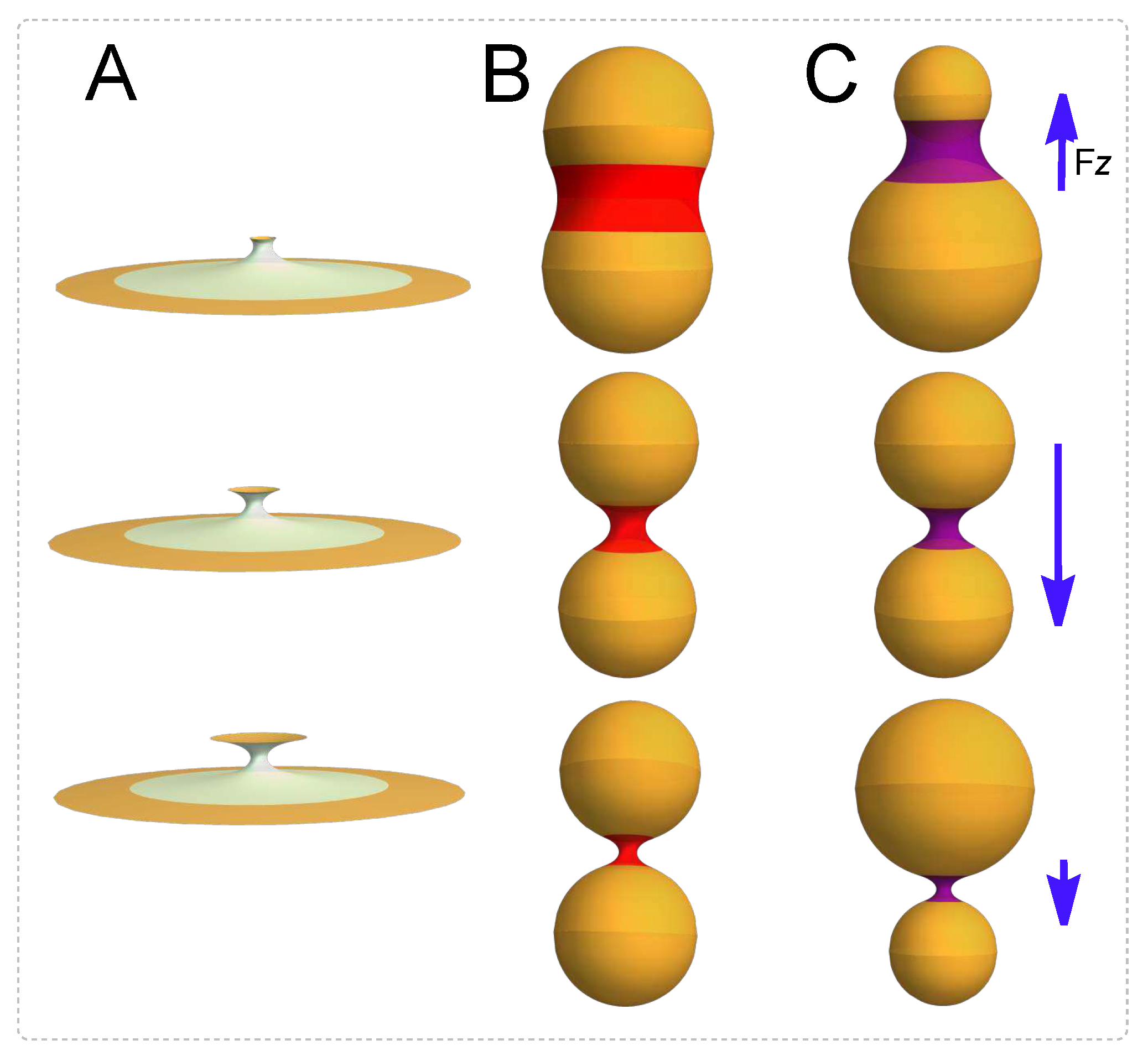
-inhomogeneities on the mechanical anisotropies of catenoidal membranes. The curvature-covariant framework is exploited to analyze some biological necking processes as depicted in
Figure 1. We have obtained the interaction force between the catenoid boundaries and then focussed on the mechanical balance along the axial and radial directions. The presence of a constant external field of neck stretching
, balances the axial force
, whilst the radial balance requires a constrictional external field variable along the
z-coordinate,
. In a typical necking abscission process like the one shown in
Figure 1, there is a critical catenoid such that the axial force
request an abrupt change from being a positive tension to a negative one. This change results in a compositional switching for the distribution of the spontaneous curvature,
. Weather the necking process is symmetric, as illustrated in column B, the radial force between the borders has been shown undergoing either repulsive or attractive interactions akin a diatomic molecule. For small relative radii corresponding to incipient constriction (thick catenoid), this interaction appears repulsive. However, in a small region close to a critical minimum, the radial force becomes attractive. Finally, for the larger radii corresponding to high pinching constrictions and for large radii (thin catenoid), the borders have no interaction. Whereas the critical catenoid and the catenoid of maximum area are the same geometric object in symmetric necking (
Figure 1B), smaller membrane area reorganizations are involved in the asymmetric cases (see
Figure 1C). As a further insight in the covariant mechanics of abscissional membrane catenoids, we describe the geometric criticality behind such inhomogeneous necking physics.
2. Materials and Methods
Surface geometry. A generic surface in
, with cartesian coordinates
, can be parametrized by the embedding function
, where
are local coordinates on the surface
. The infinitesimal 3D-Euclidean distance
, induces the corresponding arc length distance on the surface
; here
is the induced metric, and
are two local tangent vector fields. Correspondingly, the induced metric defines a covariant derivative on the surface denoted by
. The unit normal to the surface is
, where
with
being the Levi-Civita alternating simbol and
. The Gauss equation establishes
, which describes the change of the tangent vector fields along the surface. The components of the extrinsic curvature are defined as
, which are related with the Gaussian curvature
through of the Gauss-Codazzi equation,
, and its contraction
[
33]. The Codazzi-Mainardi equation
, will be also useful.
Inhomogeneous elastic energy. As defined by the Canham-Helfrich functional describing mean-field curvature elasticity [
31,
32]; for the inhomogeneous case, we are state:
where
and
represent the constant (globally averaged) values of the flexural rigidities for, respectively, bending and saddle-splay modes. Here,
is the differential volume element (the integrated volume is enforced constant under hydrostatic pressure
P). Both, the spontaneous curvature (
), and the surface tension (
) are considered inhomogeneous functions of the membrane coordinates i.e., they are variable quantities that depend on the local stresses. As a strong condition for membrane heterogeneity, the local surface tension
has been introduced as a coordinate-dependent Lagrange multiplier, which locally fixes the surface area of each membrane element. Although the Gaussian term determined by
is always considered as a conserved quantity involved till complete scission is explicitly considered (it remains constant without topological change: Gauss-Bonnet theorem [
33]). This topological invariant becomes chiefly relevant into the boundary terms considered for necking.
Let us notice the membrane inhomogeneous state-variables , and as accounting for the local values of lateral tension, and spontaneous curvature, respectively. As a reference state, we consider a homogeneous sphere of radius R, which represents the ground state as far as a constant spontaneous curvature coincides with its natural curvature, i.e. . In the event that such spherical cell is deformed without topological charge, membrane inhomogeneities do appear in spontaneous curvature and lateral tension as a mechanical response requested to maintain equilibrium.
Stress tensor. Under an infinitesimal surface deformation,
, the variation of the energy is written as
, where
is the stress tensor [
34,
35]:
with tangential and normal components, respectively:
For closed membranes (spherical topology) the hydrostatic pressure term
is considered within the energy in Eq. (
2); the difference
is the pressure jump that supports the membrane vesicle, and
V the enclosed volume. For closed (topologically spherelike) cells mechanical equilibrium, the surface divergence of the stress tensor is hence found as
Therefore, substituting Eq. (
3) into Eq. (
5), the equilibrium conditions can be restablished in terms of the stresses in Eqs. (
4) as
These equilibrium equations define the generalized theoretical framework for calculating constitutional relationships corresponding to the inhomogeneous mosaic-like membrane. They determine the membrane shape in terms of locally inhomogeneousl elasticity (as given by variable elastic parameters).
Inhomogeneous CH-membrane: local shape equations. Specifically, Eq. (
4) provides analytic expressions for the local stresses compatible with the inhomogeneous CH-membrane, as considered at global mechanical equilibrium i.e., under
. By substituting particular expressions of Eq. (
4), in the generalized equilibrium equations of Eq. (
6), one immediately gets the inhomogeneous connections between local elasticity and curvatures.
The first condition in (
6) accounts for mechanical stability along the normal direction:
which describes the connection between local shape and Laplace pressure at any point in the membrane. In the homogeneous case (for constant
and
), Eq. (
7) reduces to the well-known Helfrich’s shape equation [
36,
37].
The second condition in Eq. (
6) accounts for the lateral equilibrium relationship, or equivalently stated, as an inhomogeneity connection between the spontaneous curvature and the tensile stress in the tangent plane through of the geometric shape, this is:
This result is especially interesting as it connects the changes of constitutive properties in a causal relationship modulated by the local value of mean curvature. Being completely novel in the analytical form here presented, the concept is also quite intuitive in biological terms, hence being useful for interpreting the mechanical impact of compositional agents for mosaic curvature making.
Closed vesicles: directional stresses. After integrating Eq. (
5) in a closed geometry, by taking advantage of the divergence theorem, we get:
where
C represents the boundary for an arbitrary contour for membrane patch
. The left hand side of Eq. (
9) represent the elastic force which the membrane domain
exerts onto the rest of the closed vesicle
. Nevertheless, this force is manifested on the membrane boundary
C, independently of its particular shape and/or size changing under deformation. The right hand side states that, at equilibrium, this deformation work is equalized to the normal pressure flux across its membrane area. The integral is then calculated along the loop
with tangent
, and conormal
as defined in the Darboux frame adapted to the curve
C.
In the Darboux basis, the force term in the l.h.s. of Eq. (
9) is:
with separated elastic force, per unit length, along each relevant membrane degree of freedom; these are respectively, tangential, normal and lateral,
Here, the curvature gradients are expressed as
,
,
and
.
Similarly, in order to calculate the force that a meridian region does exert on the adjacent side, we project the stress tensor on the meridian loop i.e.,
. Then,
where the projections are
for the directional derivative along the tangent,
.
Open membranes: boundary conditions. For open membranes considered hydrostatically depressurized with respect to surrounding ambiance (
), the boundary conditions are given by [
39]
The first condition in Eq. (
14a) implies that, on the boundary edge, the torque is proportional to the projection of the extrinsic curvature,
, on the tangent vector,
(the normal curvature of the boundary curve); being the constant of proportionality the relative Gaussian stiffness as referred to the bending modulus,
. The second boundary condition, Eq. (14b), identifies the local density of membrane energy on the border edge with the Gaussian curvature therein, and involves the geodesic curvature of the border,
. Finally, the dot on
in Eq. (14c) represents the derivative respect to the arc length of the boundary edge.
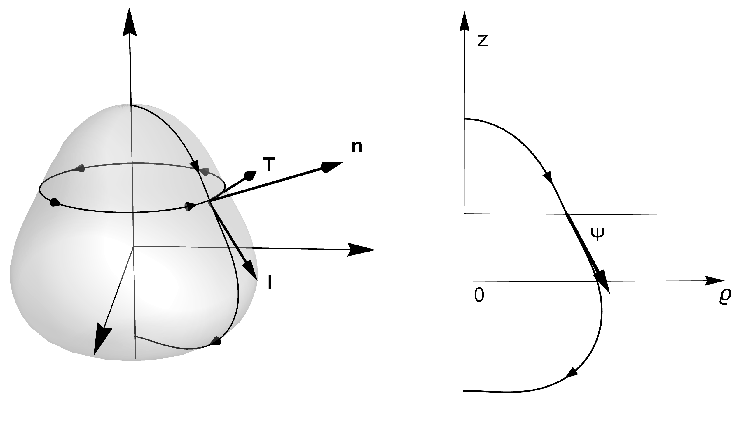
Axial symmetry: surface membranes of revolution. Axial membrane with cylindrical symmetry is described in
Figure 2, parametrized in terms of the inclination angle (
), and the radial coordinate (
). In these axisymmetric coordinates, the projection of the extrinsic curvature onto the conormal vector field
is given by the projection
(where the symbol ’ means the derivative respect to the arc length
l). On the unit tangent along the parallels to the equatorial plane, we have the condition
, which indicates their flexural curvature. We have also the rotational projection normal to the revolution
z-axis, i.e.
, which indicates no change needed for extrinsic rotational strain to generate the axially symmetric revolution surface. The Gaussian curvature is given by
, which is the canonical parametrization for the intrinsic curvature (Gauss’ Theorem
Egregium). Such definition as the relative curvature of the parametric curve depends only on the intrinsic distances measured on the surface but not on how it is extrinsically embedded in Euclidean space. In terms of the tangential inclination angle
, the (twice) mean curvature is given
. Therefore, the projections of the force in the Darboux frame, Eqs. (11), are respectively given as
Similarly, in Eqs. (13) the meridian projections can be identified as
Axial and radial forces acting through parallels. By taking advantage of the axial symmetry, we project the stress tensor along the meridian generatrix
(see
Figure 2). Consequently, the forces per unit length decomposed on the axial and the radial directions are:
where
and
, are given by Eqs. (15b) and (15c), respectively. Further, multiplying by the factor
, the corresponding necking forces are obtained (see below).
A further integration of Eq. (
5) within the axial open neck symmetry yields the mechanical balance equations on parallels and meridians. They are equivalent to the equilibrium equations obtained from the variational Lagrangian analysis in cylindrical coordinates [
38].
3. Julicher-Seifert variational approach
As devoid of the conserved Gaussian term, the functional
in (
2), can be re-written in cylindrical coordinates as an action integrated over the generatrix parameter [
38]:
where the Lagrangian function is given by
and the Lagrange multipliers
, and
, have been added, so that the Euler-Lagrange equation respect to
and
, get
and
. Further:
Euler-Lagrange equation respect to the inclination angle
, gives
where we have considered Eq. (15b). Hence, Eq. (
20) corresponds to the mechanical balance along the unit normal to the surface; note that the term between parentheses actually corresponds to the projection of the constrictive force,
, along the unit normal, i.e., Eq. (
20) may be rewritten as,
, which indicates the mechanical balance between normal stress and necking constriction.
Euler-Lagrange equation respect to
gets
where we have substituted Eq. (
16a) in order to obtain the final form in the second line. This equation corresponds to the balance of forces, per unit length, that acts through meridians along the tangential direction.
Euler-Lagrange respect to
z, is given by
, so that
is a constant. This result is a consequence of the Lagrangian symmetry on translations along the axial direction. This is the analogue of Eq. (
21), on the axial direction,
where we used Eq. (16c).
Since the parameter
l, does not appear explicitly in the Lagrangian,
L, the Hamiltonian function,
, along the membrane [
38]. As a consequence
where we have used Eq. (15c). This equation represents the balance of forces along the lateral direction. The term in parentheses is the projections of the constrictive force,
, as calculated along the unit conormal
, i.e. Eq. (
23), can be expressed as
Finally, in cylindrical coordinates, Eq. (
8) is re-stated
Thus, the relationship between the balance equations and the Euler-Lagrange equations, has been clarified in the natural coordinates for describing the necking process, and further generalized to the inhomogeneous case. As a relevant example in the focus of this paper, let us analyze the necking case of the catenoid, which is a minimal surface that implies analytical solutions for the spontaneous curvature.
4. Results: Catenoidal necks
Equilibrium necking equations.Figure 3 depicts a generalized axial neck symmetry implying the systemic equations not depending on the azimuthal angle around the parallels but on the arc length parameter (
l as describing neck latitudes in the generating meridian); this generatrix is mechanically inhomogeneous with origin at the neck equator (
; see caption for details). The catenoid is a minimal surface, such that the mean curvature is zero elsewhere (
). Therefore, the analytic integration of Eq. (
24), gives the conservation equation
where
,
and
, being
a constant of integration. This can be determined by the boundary condition, Eq. (14b), as
, where
, denotes the most northern latitude at the upper boundary (see
Figure 2).
Therefore, the energy density is determined by the Gaussian curvature,
, at the boundary. In dimensionless variables, the mechanical balance along the axial and radial directions is obtained by using Eqs. (17), (
20), and (
23); the corresponding equilibrium equations are given respectively by
where
,
, and
.
By using the parametric equation of the catenoid (see the caption in
Figure 2), the axial and radial mechanical balance on any parallel curve of the catenoid (see
Figure 3), holds respectively:
where the scaled elastic forces along the axial and the radial direction as the relevant necking forces under the membrane tension; these are
for the dimensionless stretching tension (considered constant and homogeneous in order to preserve the axial symmetry under translations), and
, for the radial constrictive tension (considered essentially inhomogeneous).
Differently to the homogeneous case (for the constant
), the meridian gradient of spontaneous curvature is herein identified to be normal force that a region bounded by a parallel does exerts on an adjacent region. Thus, in both Eqs. (
28a) and (28b) the first term in lhs is the contribution of the normal force, whereas the next two terms are the lateral forces acting through the parallel of coordinate
. Evaluating Eq. (28b), at the equatorial loop,
, gives that constrictive necking force as the local change of spontaneous curvature i.e.,
; thus, in the case of a symmetric distribution of
along the membrane, the force
. According to Eq. (28b), in the symmetric case the scaled radial force,
, is an odd function of the arc length parameter
, and Eq. (
28a) holds the relationship between the axial force and the spontaneous curvature at the waist of the catenoid; this is
. Although in the symmetric case, the constrictive force vanishes i.e.,
, the scaled intrinsic torque has the maximum intensity at the waist of the neck; this particular property happens because the torque,
, (associated with local flexures around the loop), is given by the spontaneous curvature itself,
. In general, the inhomogeneous spontaneous curvature does appear as a net torque arising for flexural neck shaping i.e.,
, whereas its local change as a normal force (due to inhomogeneity) determines the constrictional stresses emerging from the equilibrated equator i.e.,
. As an original result of this work, below we obtain the necking solutions for inhomogeneous catenoids.
4.1. Inhomogeneous solutions: necking forces
Once the balance equations have been established into the relevant directions, we obtain solutions for the inhomogeneous spontaneous curvature
, these are
as written in terms of the even function
The constrictive force
, appears here naturally as an integration constant for the spontaneous curvature force. On the border of the catenoid we may write the function,
, where
(see
Figure 3). Solutions in Eq. (
29) are modulated by constitutive forces referred to the relative elasticity parameter
, defined as a control parameter for retaining further bending on the natural saddle-splay of the catenoid neck; these solutions are:
the bending-rescaled axial tension (
); and
the border spontaneous curvature stress as recapitulated by
. The boundary conditions
[
39], yield the bounding values of spontaneous curvature from which the constitutive parameters
and
, can be found as
where the function
. Substituting Eqs. (
30) and (31) into Eq. (
29) gets the distribution of the spontaneous curvature along the catenoid as the domain-renormalized function
, defined in the interval
.
Equations (
30) and (31), respectively provide the constrictive radial force at the neck equator (necking waist constriction), and the axial force (a constant stretching) both in terms of the upper radii
, and the lower radii
, of the catenoid. Nevertheless, using Eq. (28b), it is possible to obtain an analytical expression for the radial force at any parallel in terms of the border radii and the arc length of the meridian generatrix. The constrictive force along the catenoid is given by
where
is given by Eq. (
30) and
By evaluating Eq. (
32) at
, we reproduce the necking force
.
4.1.1. Symmetric solutions
On a symmetric catenoid (defined as
), the necking force equals naturally zero i.e.,
, whereas the scaled axial force
hence, in the symmetric neck the scaled spontaneous curvature simplifies to
. Because the function
, is either positive (or negative) for
(or
), we identify two different constrictional domains separated by a critical point (at
), which also describes the maximal area
. In the subcritical regime (
), the function
decreases monotonically from unity down to zero (at
). This necking mode makes the spontaneous curvature inhomogeneously positive (
) [
4], which corresponds to an initially elongating neck appearing a surface predominantly cylindrical (low constriction, leading neck stretching). At the critical point (
), the symmetric critical catenoid exactly fulfills the geometric condition
(also of maximal area). In the supercritical regime
, however, the function
shifts to negative, hence making the inhomogeneous spontaneous curvature to become negative in a predominantly concave neck geometry (high constriction, leading scissional pinching). In this regime, as
, the spontaneous curvature is distributed almost homogeneously, making it zero asymptotically. Consequently, the axial force is positive in the subcritical regime (
, if
) and negative in the supercritical regime (
, if
). In both off-critical regimes, the boundary-edge relationships are satisfied (Eqs. (
14a)), whereas at the critical point these may be verified using the L’Hopital’s rule. Note that at the catenoid waist, the scaled spontaneous curvature is given by
, which takes large positive values if
approaches the critical point from the left (
), whereas it takes large negative values approaching from the right (
). If the symmetric function
, is substituted in Eq. (28b), we find that the radial force,
, is an odd function of the arc length
, so that it vanishes at the waist of the neck, and attains its maximal intensities at the border. In
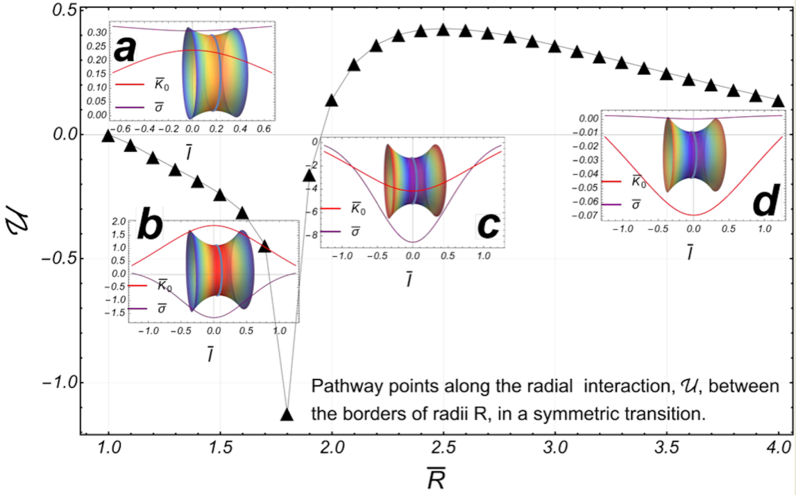
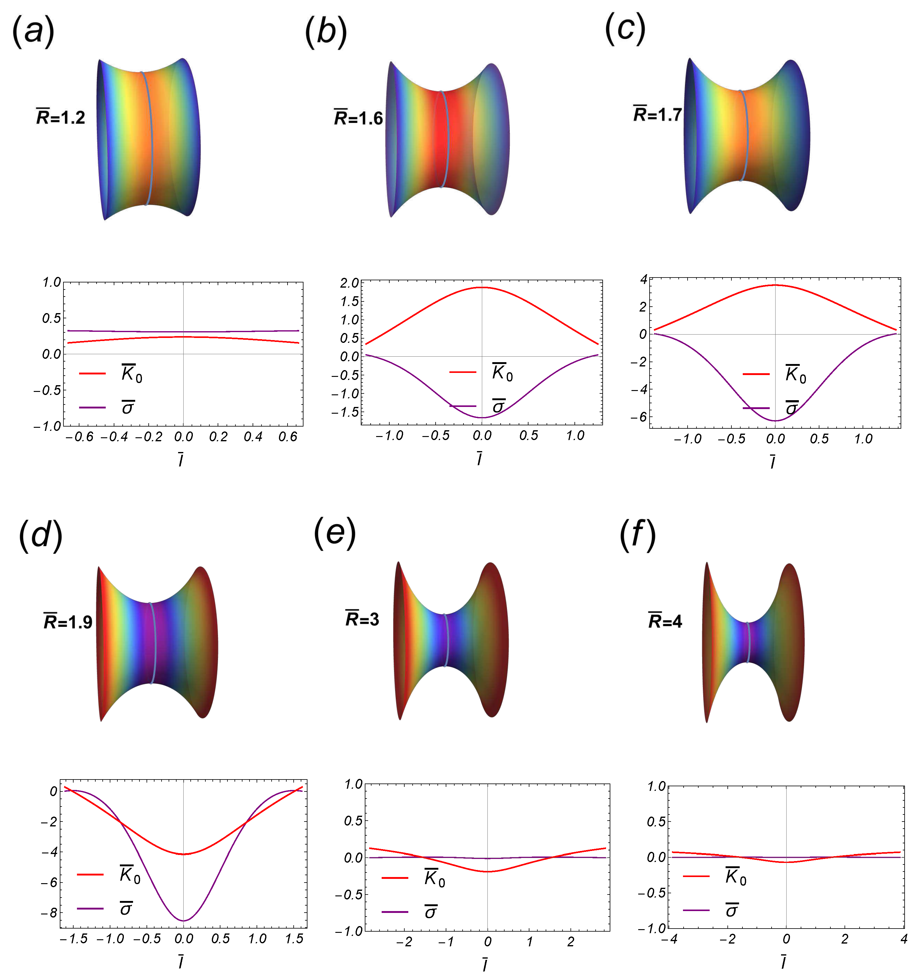
Figure 4, some stages of the necking pathway have been depicted for a particular case compatible with experimental rigidities (
). Notice the abrupt change in the inhomogeneous distribution of
as passing through
(see Figure 8). By particularizing Eq. (
32) to the symmetric case (
), the scaled radial force
is given by the odd function
Further evaluation of this force on the lower border,
, gets the constrictional force in terms of the edge radii:
An isolated singularity appears at the critical point
. If
(high constriction), we have
; instead, if
(low constriction), then
. More detailed information about the strength of the interaction can be obtained by numerically integrating the radial force. Particularly, the work
W performed by the radial force
, to make evolving the lower border (from
to
), gets the associated energy,
, through
An interesting behavior emerges from the singularity in the radial force. Close the singular point
, the function form vanishes linearly as
, so that the corresponding singularities in
W are cancelled out.
By attending to this necking work as a change of potential energy in the symmetric case here considered, the borders of the catenoid have no interaction for large radii (i.e., for
), then
. The numerical result is the energy function,
as shown in the
Figure 4 panel
as black triangles (we have taken
). Let us notice the presence of a global minimum at the critical point
, as well as a point of maximum energy at
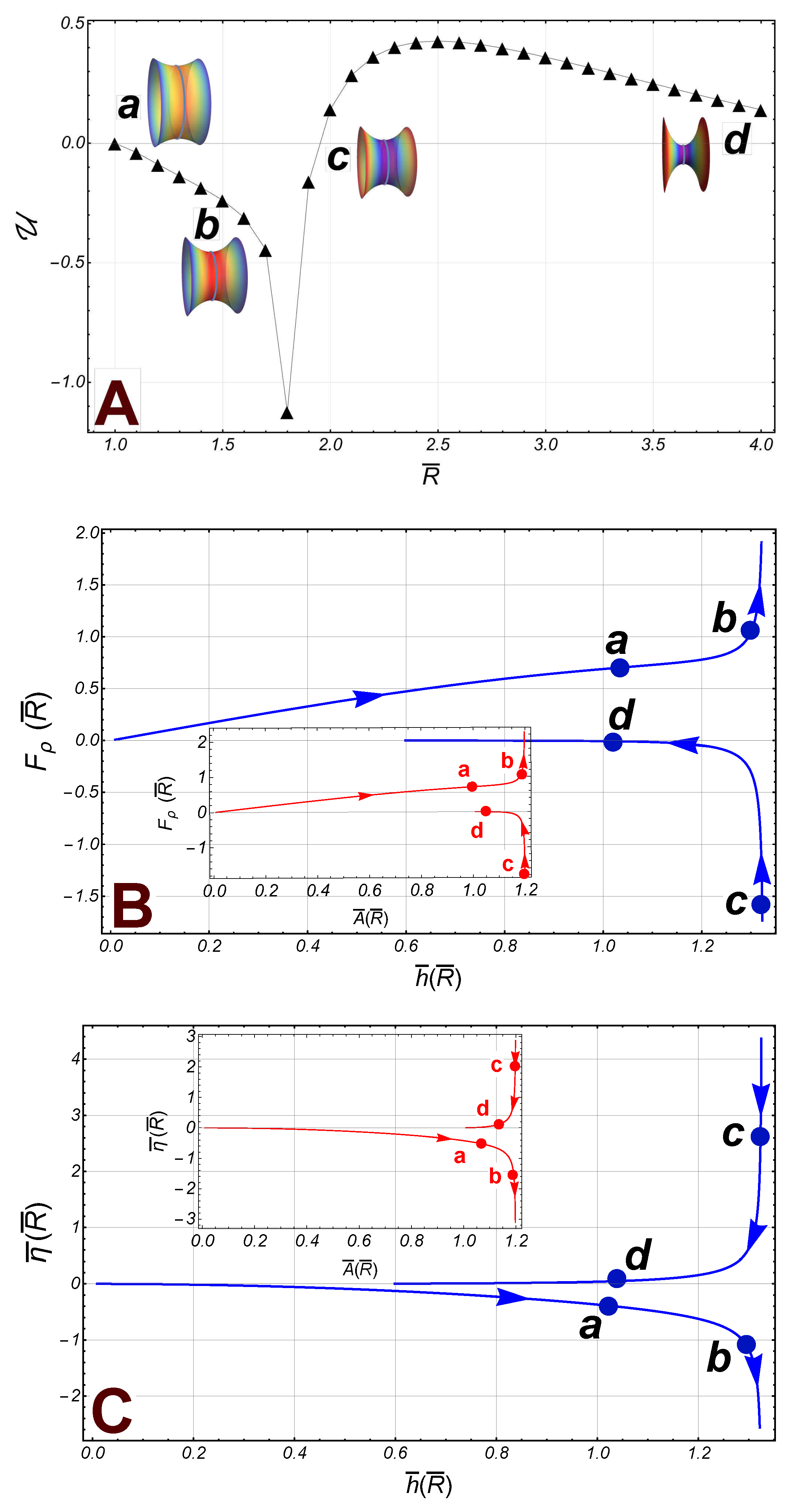
. As regarding the corresponding forces, in the subcritical sector
, the radial force on the border
, is repulsive from the axial axis, whereas the axial force is attractive in this sector i.e.
(see
Figure 4 panel
, pathway points
and
). In approaching the critical point (
), both the area,
, and the height,
, increase until reaching the size of the maximum catenoid such that,
, and
; both the radial and the axial force diverge at this point (see
Figure 4, panel
and
). In the supercritical regime comprised between the critical point and the energy barrier (
), the radial force is attractive, and the lower border is repelled out with an axial force that tends to zero very quickly (see
Figure 4 panel
). Finally, a relaxation regime appears at large constrictions leading final pinching scission above the barrier (
); in this sector, the radial force is again repulsive and decreasing with
, tending to zero for a very thin catenoid, i.e., such that
. Thus, in this abscissional limit the boundaries do not interact each other, although the separation decreases strongly (
), and the area
(see
Figure 4, panel
and
, pathway points
and
).
4.1.2. Asymmetric solutions
Let us now analyze the general asymmetric case such that the upper border is fixed to
, and
. The axial force is still given by Eq. (31), so that if the lower border
, then the axial force
. Hence, if
, the lower edge is repelled out from the upper one; in contrast, if
, the lower border is conversely attracted thereby. Further, the radial force on the lower border is given by Eq. (
32); if substituting
, we found:
In the regime of high constriction (
), then
, so that the radial force on the lower border is repulsive from the axial axis, regardless of
. Despite the absence of mirror symmetry in this case, the radial force (
37), presents also a singularity at the point
, determined by the condiction
. Nevertheless, for some values of
, there exists a certain value of the radii
, such that the singularities in the last two terms in Eq. (
37), cancel out each other. Henceforth, such particular condition for asymmetric critical necking will be referred to as a
separatrix. For the reference result (at
), we found that
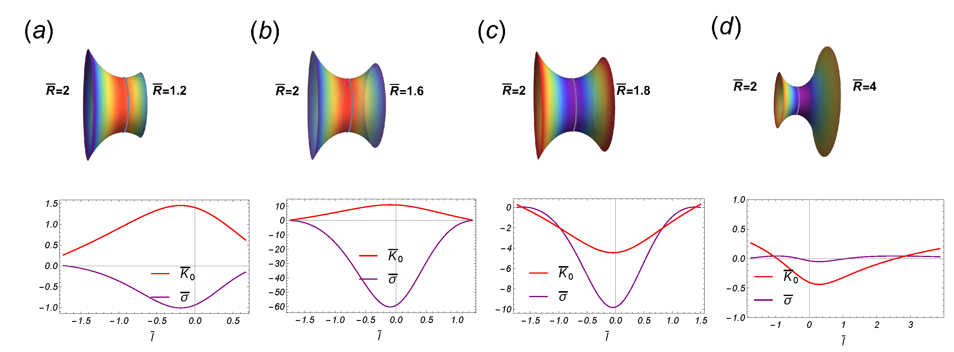
. The behavior of the spontaneous curvature close the critical point has been depicted in Figure 9, in the case of fixed
.
As shown in
Figure 5, two types of behavior are found divided by a separatrix curve defined for the fixed radii,
: If the upper radii is fixed to
, in the subcritical sector (
), the radial force is positive on the lower border, i.e., is repulsive from the axial axis. In the supercritical sector (
), it becomes attractive in a small domain close to
, but recovers a repulsive character beyond this domain. As shown in
Figure 5, for fixed radii
, the opposite behavior occurs close the critical point.
4.1.3. Solutions on the separatrix
We consider the case studied for fixed upper radii
(
). In
Figure 6, panel
, the radial energy
is shown as a function of the lower radii
. Some pathways are points identified: The inset
, shows a catenoid with
(the right border). The spontaneous curvature
, and the surface tension,
, are outlined as a functions of
. The lower value of
, corresponds to the left border; the point
, has been marked with a loop on the catenoid while the right border corresponds to the higher value of
. Similarly, the catenoid at the inset
corresponds to radii
, while the catenoid at
, corresponds to
. Note the abrupt change in the behavior of
(let us compare
in the panel
, and the panel
). In this case the transition point occurs at the singular point,
(i.e., at
). However, this singularity is canceled out as appeared in the radial force as far as the energy function
, is a smooth function itself. At the barrier maximum
the spontaneous curvature shifts to negative at the waist (see the inset
in the panel
), close the global maximum of the energy
; here, the radial force vanishes
. The continuos behavior of the radial force can also be observed in
Figure 6, panel
, where it has been outlined as a function of the distance between the borders (
). Following the pathway points in the panel
, the catenoid of maximum size reaches at
, such that
, and
. After this point, the radial force increases giving rise to a decreasing the height of the catenoid (see the points
, and
). In the same way, the catenoidal area decreases beyond the maximal catenoid and approaching to the limit
(see the inset panel in
Figure 6). Nevertheless, the singularity in the axial force
, does not cancel out (see Eq. (31)), which manifests in the two branches separated by the critical point (see
Figure 6 panel
).
To recapitulate, in the region such that , the radial force is attractive towards the axial axis on the lower boundary (right if shown axially horizontal), and decreases with until it reaches the size of the maximum catenoid at . The axial force is strongly attractive as it approaches the singular point . If the radii , the axial force is now repulsive, decreasing rapidly with , until vanishes; in this sector the radial force remains attractive and decreases to zero if the radii (the point of the maximum energy ). After this point the radial force is repulsive and, in the sector , it increases slightly with . Although the energy does not exhibit any singularity at the critical point, , there is an abrupt change in the behavior of the spontaneous curvature passing through this point.
4.1.4. The fixed radii, .
If the upper border is fixed to be
, then we have that
, so that the necking force
, and
. Thus, the axial force
, and the spontaneous curvature is given by
where
. As being a function of
, Eq. (
38), does not show any singularity. On the lower boundary, the radial force is given by
This force does not present any singularity either; it vanishes if
exactly. For
, we have
, and
, if
. Thus, close to
, the radial force is attractive towards the axial axis if
, and repulsive if
. However, if
, the force is repulsive regardless of
. Further, for large radii
, the energy
. In this case, the integral can be calculated exactly, so that the energy is given by
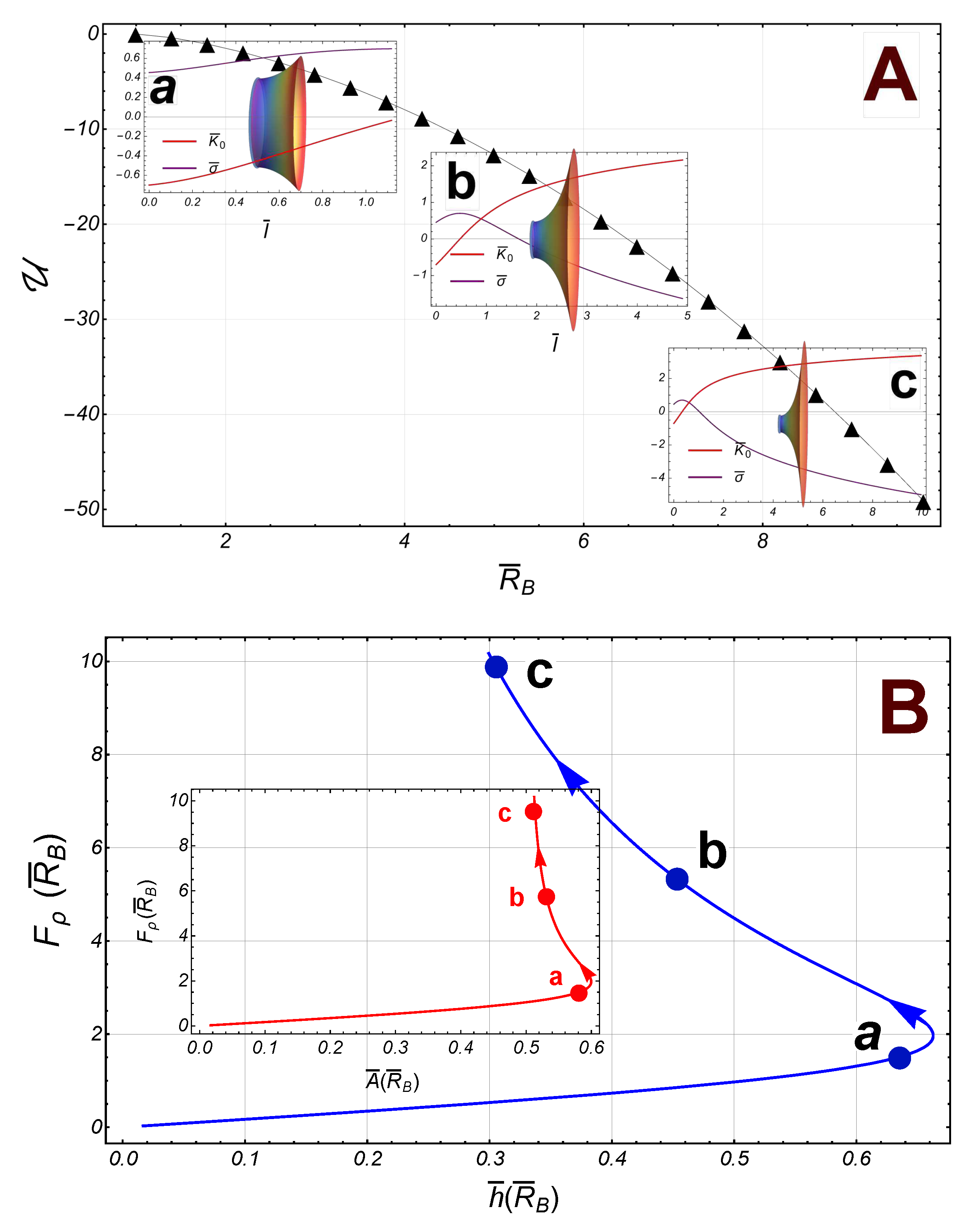
Some numerical results have been depicted in
Figure 7 (we have taken
). In contrast with the symmetric case, the energy
, is a decreasing smooth function of the radii
, so that the radial force on the lower border (the right border in the
Figure 7), is also increasing. For small values of
, the area,
, increases until it reaches its maximum value at the point
, then it begins to decrease such that, if
, the area
; similarly, the separation between the borders,
, reaches its maximum value at
, then it decreases furthe and finally, in the asymptotic limit
(see
Figure 7)).
5. Discussion
In the first part of this work, based on a generalization of the Canham-Helfrich model, we have established the Euler-Lagrange equations in cylindrical coordinates in terms of mechanical balance. In this framework, the spontaneous curvature does depend on the membrane shape as well as on the inhomogeneities in the surface tension. To isolate the effect of these inhomogeneities, in the second part of this work we focus on a catenoidal shape membrane. Since that the borders of the catenoid have different radii, all the quantities have been normalized relative to the waist radii . It is found that, for large values of the lower border radii ( fixed), the radial force on the lower boundary is repulsive according to , regardless of the Gaussian stiffness (); thus, this repulsive force is proportional to the radii , and the presence of the radii has the effect of damping this force. Clearly, the damping effect is minimal if the radii is fixed to .
Solutions belong to two possible branches separated by the critical catenoid, which is reached for some value ; it is identified as a critical point in the sense that it signals an abrupt change in the behavior of the spontaneous curvature. In the symmetric case, such that the two radii borders are equal, say , the critical catenoid and the catenoid of maximum size are the same, reached for . In addition, if we assume the experimental result, , the energy of interaction between the borders attains its global minimum at . Thus, the radial force is repulsive for short distances, attractive in a sector after , and for large radii, tends to zero as .
The distribution of the spontaneous curvature
, and the surface tension
, has been depicted in
Figure 8 and
Figure 9 in the symmetric transition and the asymmetric (for fixed
), respectively.
There are two other relevant cases, one of which being with the fixed radii . In contrast with the symmetric case, the two branches of the radial force reduce to a continuous curve, whereas the axial force is zero. Therefore, there is neither a critical point nor abrupt changes in the spontaneous curvature. The radial force on the lower border, for large radii , increases as . As mentioned above, this is the case of maximum repulsive interaction on the lower boundary of radii .
The last case we have analyzed is the separatrix. The relevant feature of this curve is that for some value of the ratio , there exists a certain value of the radii, , such that the singular behavior in the radial force cancel out. For the value , it is obtained that , so that for large radii , the radial force , is very weak compared to the case of fixed . However, the axial force still presents a singular behavior at the critical point , and is therefore separated into two different branches. The presence of this divergence results in the swith transition in the spontaneous curvature. Clearly, in this case the critical catenoid does not coincide with the one of maximum size, which is reached at the radii . It is worth emphasizing the behavior of the curves for the radial force: if , the curves are increasing in their domain while if , they are decreasing, being the separatrix the dividing curve between both behaviors. More details about this behavior should be analyzed both in theoretical and experimental terms.
Figure 1.
Membrane neck dynamics under scissional forces. A): A necking process describing the membrane necks connecting scissional compartments. Two modes of membrane necking are possible. B) Symmetric mode: two spherical membranes compartments of equal radii joined by a catenoidal neck, in a symmetric process. C) Asymmetric mode: membrane compartment of different radii joined by an asymmetric catenoid.
Figure 2.
A generic closed surface of revolution. In cylindrical coordinates , it is described with the embedding function: , in the cylindrical basis , and The generating curve is parametrized with arc length l, so that , while and , where is the tangential angle of the generating curve, and the derivative respect to l denoted as a ’. The unit normal can be written as: . The unit tangent vector, adapted to parallels on axially symmetric surfaces, is given by while the unit conormal, . The orthonormal set , constitutes the Darboux basis adapted to the parallel loop.
Figure 3.
Definition of the catenoid in terms of the equatorial radii , and axial length ; , . The equation of the meridian catenary generator with fixed neck radii , is given by . The catenoid can be thus re-parametrized in terms of the reduced arc length , through the functions , and ; in the upper border , on the equatorial site, , and in the lower border . The relationship with the tangential angle of the generating curve: , and . The derivative respect to , is given by, . The area of each hemisphere is rescaled in terms of its corresponding border, thus, the rescaled surface area ; in the upper hemisphere, e.g., is given by , where . Similarly the heigh .
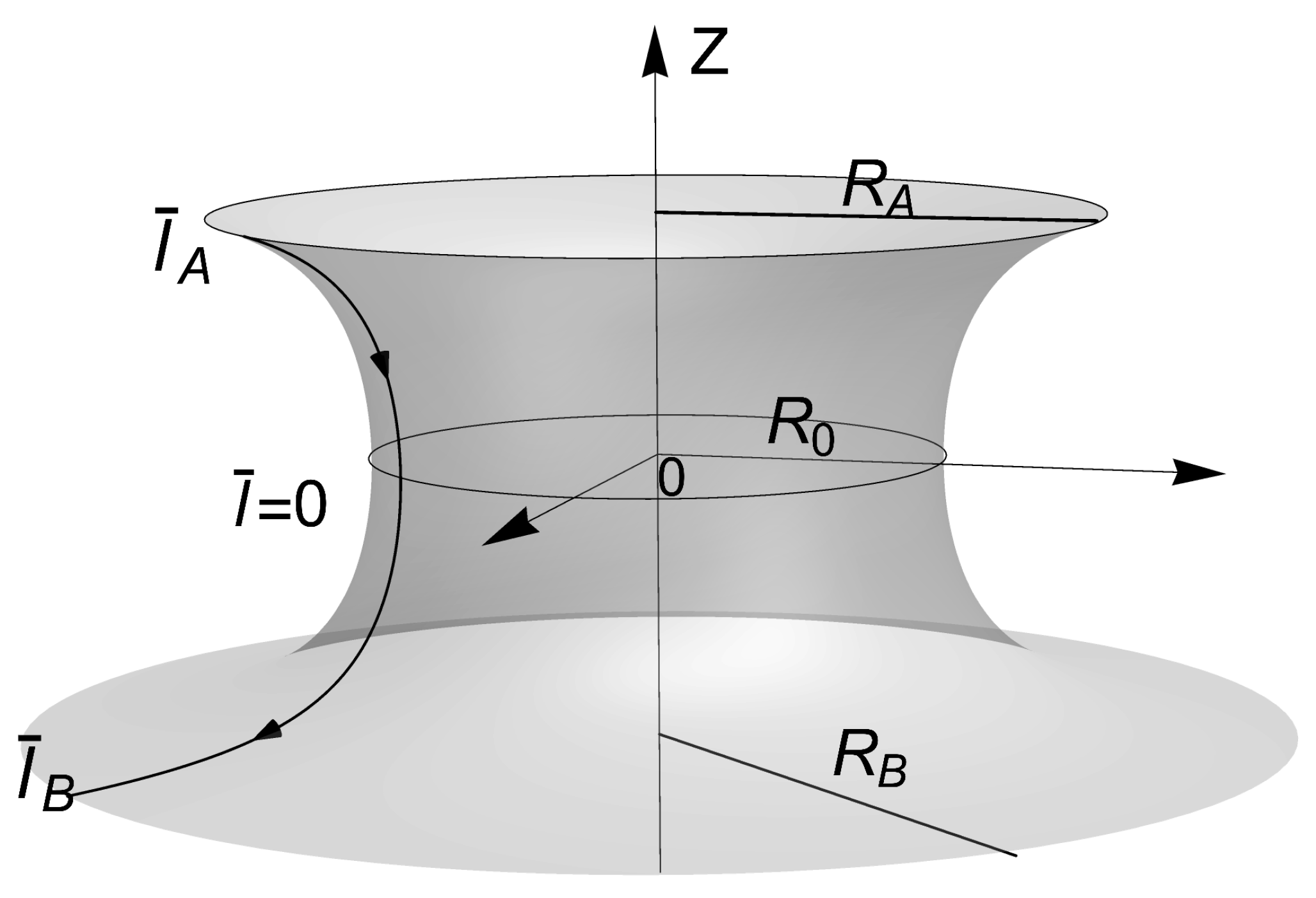
Figure 4.
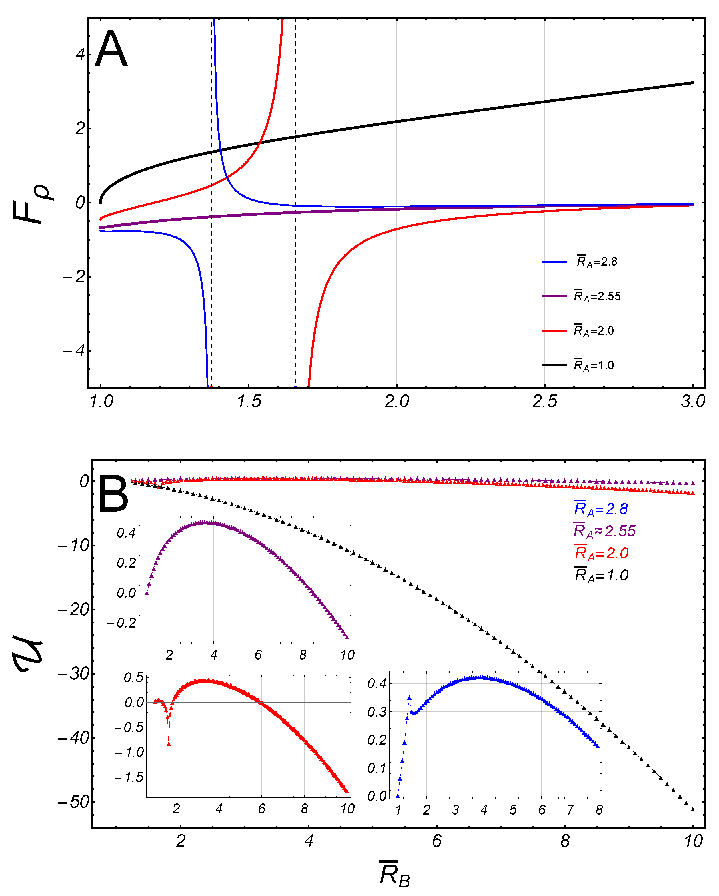
: The energy of the radial interaction (black triangles), between the boundaries of a symmetric catenoid (we have taken the experimental reference ). Some catenoidal-points of reference along the path: (), (), (), and (). The first two points belong to the subcritical regime and the last two points are in the supercritical sector. The critical point is at the point . : The radial force , on the lower border (right), as a function of (the separation distance between the borders). The inset panel outline the radial force as a function of the area of the catenoid. : The axial force , as a function of (the distance of separation between the borders). The inset panel shows the axial force as a function of the area .
Figure 5.
Asymmetric critically around the separatrix. : The radial force as a function of the radii , and fixed radii (we take ). The cases , and , do not present singularities. : The energy as a function of the radii , corresponding with the radial force in panel . The inset panels shown some details of the energy curves, , in the indistinguishable region at low necking energy.
Figure 6.
The curve separatrix (upper border fixed at radii ; ), and some catenoidal-points , as reference. The point () belongs to the subcritical regime and the points , are in the supercritical regime. The critical point is at . : The energy of interaction (black triangles), between the borders, as a function of the radii . The inset panels shown the distribution of the curvature, , and surface tension , at the corresponding catenoidal-points, as a functions of the arc length . : The radial force , on the lower border as a function of (the distance of separation between the borders). The inset panel shown the radial force as a function of the area . : The axial force as a function of the separation . The inset panel shown the axial force, as a function of the area.
Figure 7.
Numerical results in the case of fixed radii and . : The energy of interaction (black triangles), between the borders as a function of the radii . As reference, some catenoidal-points have been identified along the way: , , and . The distribution of the curvature , and the surface tension , have been depicted at the corresponding inset panel. : The radial force , on the lower border as a function of , the distance of separation between the borders. The inset panel shown the radial force as a function of the area . The catenoid of maximal size reaches at . Note that asymptotically, the area .
Figure 8.
Some stages along the transition of the symmetric catenoidal shape. In the upper panel the stages are in the subcritical regime , while the stages in the bottom panel are in the supercritical regime . For this transition, the critical catenoid and the catenoid of maximal size, are identical. In the subcritical regime, the inhomogeneous spontaneous curvature distributes positively along the catenoid and negatively (tending homogeneously to cero if ), in the supercritical sector. Note the flip-flop behavior of as passing the critical point.
Figure 9.
Some stages along an asymmetric transition, such that the upper (left) radii is fixed to be . The critical point occurs at the point . The first two stages are in the subcritical regime while the last two belong to the supercritical regime.
Figure 9.
Some stages along an asymmetric transition, such that the upper (left) radii is fixed to be . The critical point occurs at the point . The first two stages are in the subcritical regime while the last two belong to the supercritical regime.
