1. Introduction
Patients who undergo arthroplasty live longer, more active lives and receive joint replacements at an increasingly early age. [
1] As a result, total hip arthroplasty (THA) in this younger population is subject to increased physiological stress and survival is a persistent clinical concern. For older patients, implant survival rates for THA exceed 95% at 10 years, but subsequently drop to 80-85% after 18 years. [
3,
4] This is in contrast to younger patients undergoing THA, where reported survival rates drop to 72-88% at 10 years for patients under 60 and 68% for patients under 55. A few decades ago, stem breakage, coarse acetabular wear or total fatigue failure of metal femoral stems were considered as the main causes of THA failure [
2]. Nowadays, aseptic loosening, related to osteolysis of wear debris created at the joint and micro-movements at the bone-implant interface, is considered the predominant cause of revision of metal hip replacements. When revision surgeries are performed, bone resorption, related to the difference in stiffness between the implant and the host tissue (i.e., the femur) is a concern as the host bone becomes weaker and less able to receive larger hip replacements. This phenomenon is known as "Stress Shielding" and is often seen with metal implants. In addition, questor stress shielding could contribute to the concentration of stress at the bone-implant interface leading to micromovements, as recently indicated by a simulation study of the fine elements of the stems of total hip replacement (THP) [
3]. Due to the difference between the rigidity of the prosthesis material (such as alumina ceramics, titanium alloy, zirconium niobium alloy and carbon fiber composite materials) and bone stiffness, stress shielding will lead to loosening of the stem-femur connection and even fracture and other serious consequences [
2,
3,
4]. The formation of a porous structure provides a better solution to the problem of this effect [
5]. A further solution to reduce bone loss associated with stress shielding is the use of implants with an overall reduction in flexion stiffness. This can be achieved in two ways: through the use of composite materials (CF) with rigidity and mechanical characteristics closer to that of the human femur. [
6,
7], or through topological optimization. Which aims to modify the stiffness of the stem based on the Von-Mises results
1.1. Use of carbon fiber
In addition to the well-known structural mechanical properties [
8,
9], carbon fibers have some biocompatible properties that have been recognized clinically [
10,
11] through animal research [
12,
13,
14,
15,
16,
17,
18,
19] and experimentally in the laboratory [
13,
14]. Carbon fiber is lightweight with a density of 1.6 /2.2 g/
cm3 [
8,
9,
17] compared to the density of compact bone at 2.0 g/cm3 [
18]. Small-diameter, high-strength, high-modulus carbon fibers [
9,
10,
11,
12] can be shaped to fit into complex curved spaces for multiple variations in applied use. Due to the potential benefits of developing high-strength biomaterials with density closer to bone for better stress transfer and electrical properties that improve tissue formation, a test model of rat animal tibia implantation in vivo was used to demonstrate possible biocompatible improvements for carbon fiber in reinforced polymer matrix composite material. [
22]. Results showed that the carbon fiber-reinforced composite stimulated osseointegration within the bone marrow of the tibia measured as a percentage bone area (PBA) to a large extent compared to titanium alloy. Adam et al. [
20] conducted a human clinical study on a press-fit carbon fiber hip replacement with a smooth surface observing how the modulus of a carbon stem is about three times lower than metal stems and closer to the cortical bone modulus (ranging from 12GPa to 20 GPa). This study revealed that the carbon fiber composite material has the mechanical properties to withstand the physiological stress of a hip joint, but that insufficient bone fixation due to the smooth surface of the prosthesis caused early loosening of the implant. Therefore, in a study [
21] the tissue response of a carbon stem with hydroxyapatite coating was evaluated by observing a high degree of bone apposition to carbon fiber composite implants coated with HA as well as the lack of short-term inflammation and adverse tissue response to carbon fiber composite implants that supports the ongoing evaluation of this composite technology for use in THA. Moreover, as reported in Campbell et all; [
6] mechanical fatigue failures occurred after about 10
4 cycles for the maximum fatigue load of 22 kN (i.e. 123 MPa), 10
5 cycles for the maximum fatigue load of 20 kN (i.e. 112 MPa), 10
6 cycles for the maximum fatigue load of 18 kN (i.e. 101 MPa) and close to 10
7 cycles and more for the maximum fatigue load of 17 kN (i.e. 95 MPa). These results show fatigue life at least six times higher than the load levels recommended in ASTM standards [
21].
1.2. Topological optimization
Aseptic loosening of the implant is mainly influenced by the phenomena of bone resorption that are revealed in certain regions of the femur when a prosthesis is introduced. As a result, bone resorption appears due to stress shielding, i.e., the decrease in the level of stress in the implanted femur caused by the significant carrying load of the prosthesis due to its increased rigidity. A strategy based on topological optimization (TO) of maximum stiffness is used for nonlinear finite element static (FE) analyses of femur-implant assembly, with the aim of reducing stress shielding in the femur and providing guidelines for hip replacement redesign. This is achieved by employing extreme accuracy for both three-dimensional reconstruction of femur geometry and material property maps assigned as explicit local density functions. The topological optimization design method based on a methodology that allows you to determine the optimal distribution of material within a structure, in order to maximize performance and minimize weight. In the field of femoral prostheses, topological optimization can be used to design an optimal shape of the prosthesis, ensuring maximum strength and rigidity with the least possible use of material. It allows to form a continuous mechanical transmission path, which can better solve the problem of reducing the shielding of stresses. In this work both methods will be compared, and the results will be compared with a titanium prosthesis. Thanks to the finite element method adopted in this study. FEM (Finite Element Method) analysis is an engineering analysis methodology used to evaluate the structural behavior and performance of a femoral prosthesis. This computational method is based on the discretization of geometry into finite elements, which are mathematically modeled to represent the mechanical behavior of the material and the response to stresses. The hypothesis behind this study is that the decrease in stem stiffness through the modification of the section or material, actually leads to a reduction in stress-shielding
2. Materials and Methods
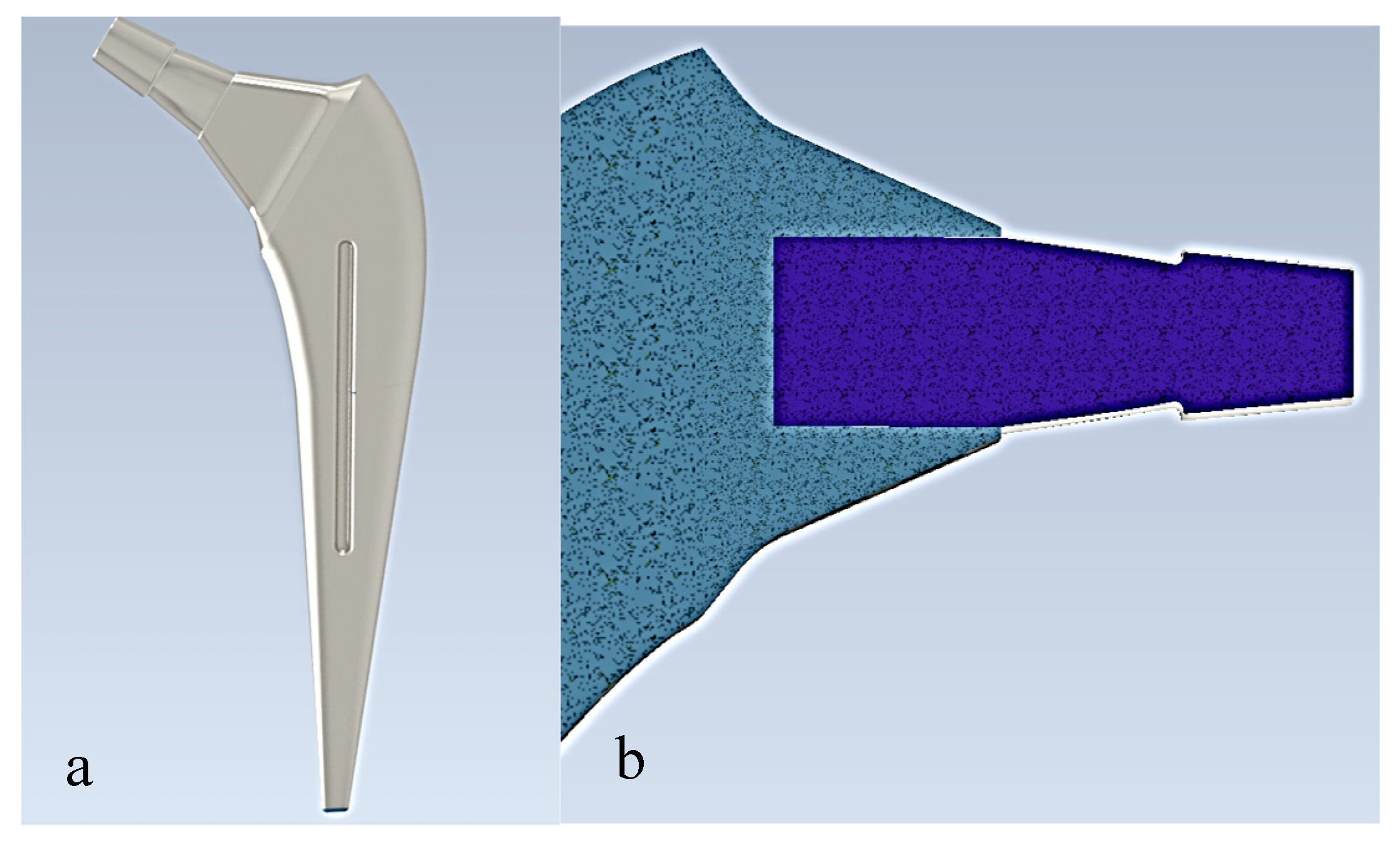
The prostheses were modeled using Autodesk Inventor as seen in
Figure 1. Autodesk Inventor is a 3D modeling and mechanical design software widely used for creating part and assembly models. The model was then transferred to the ANSYS Workbench software to analyze the system. The properties of the prosthesis material (Ti6Al4V) were assumed to be linear homogeneous and isotropic
Table 1.
Meshing
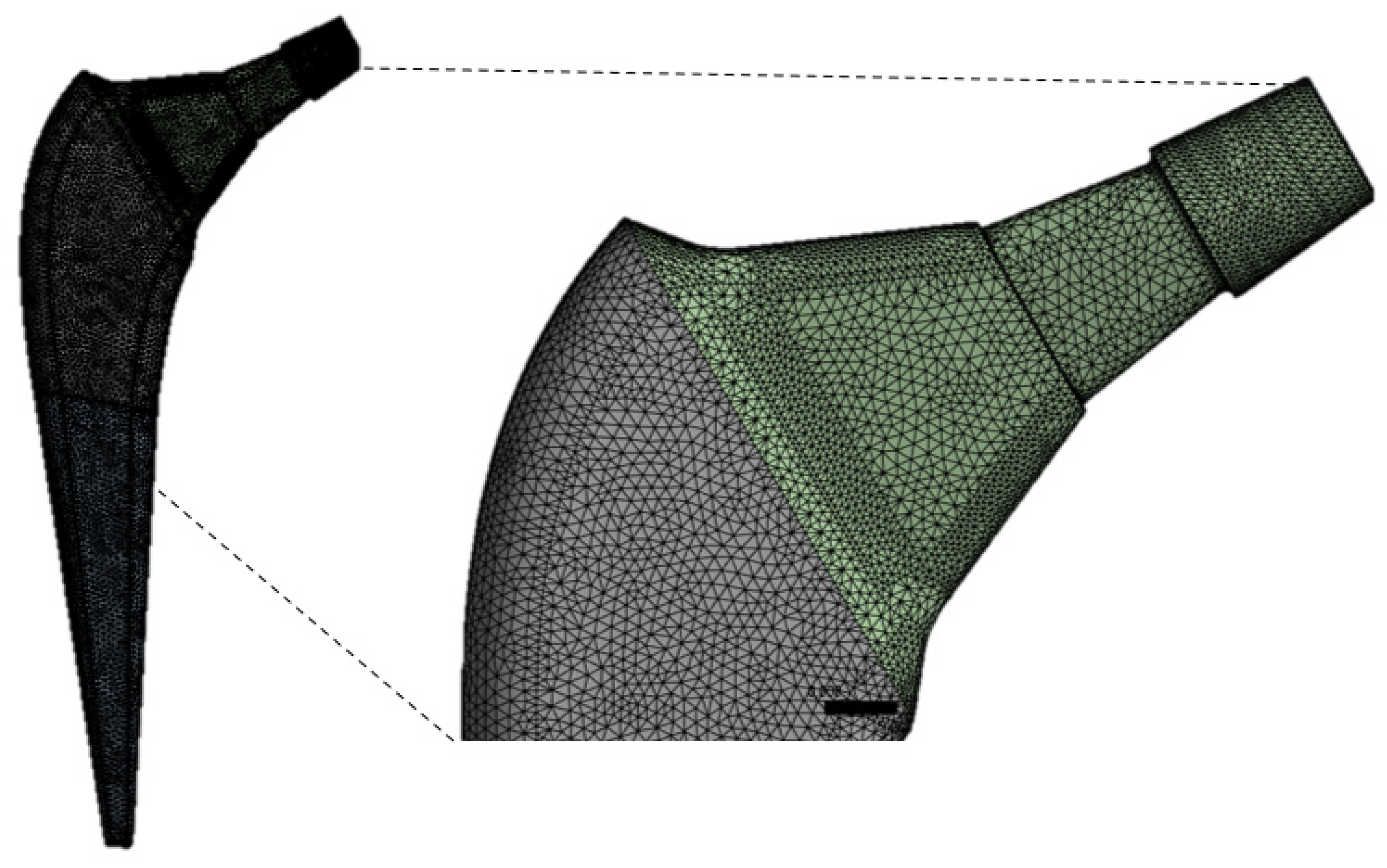
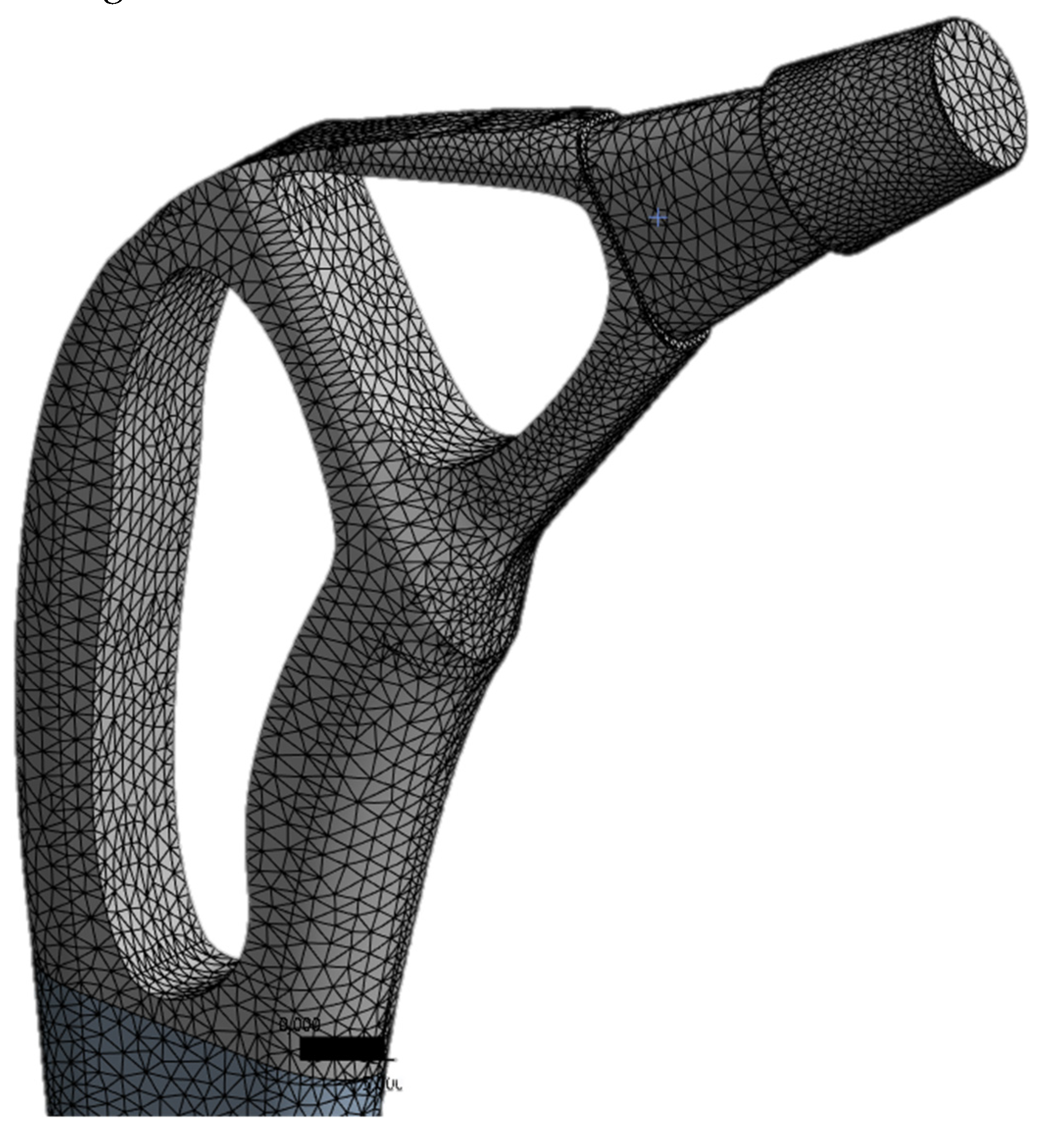
The ANSYS was used to generate the mesh. The number of nodes and elements for the present study are 629.995 and 449.179, respectively. The mesh of the implant model used ten-knot tetrahedral elements (see
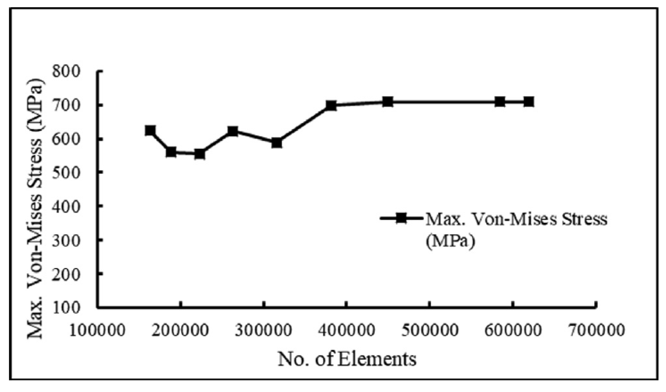
Figure 2). The tetrahedral elements were carefully inserted into irregular form of three-dimensional geometry. The optimal selection of the mesh is an important parameter to obtain accurate results. A mesh-independent study was carried out to select the appropriate mesh size.
Figure 3 demonstrates the mesh independence test, which shows the relationship between n. of elements and von Mises stress. The element size of 0.71 mm is optimal for the present study.
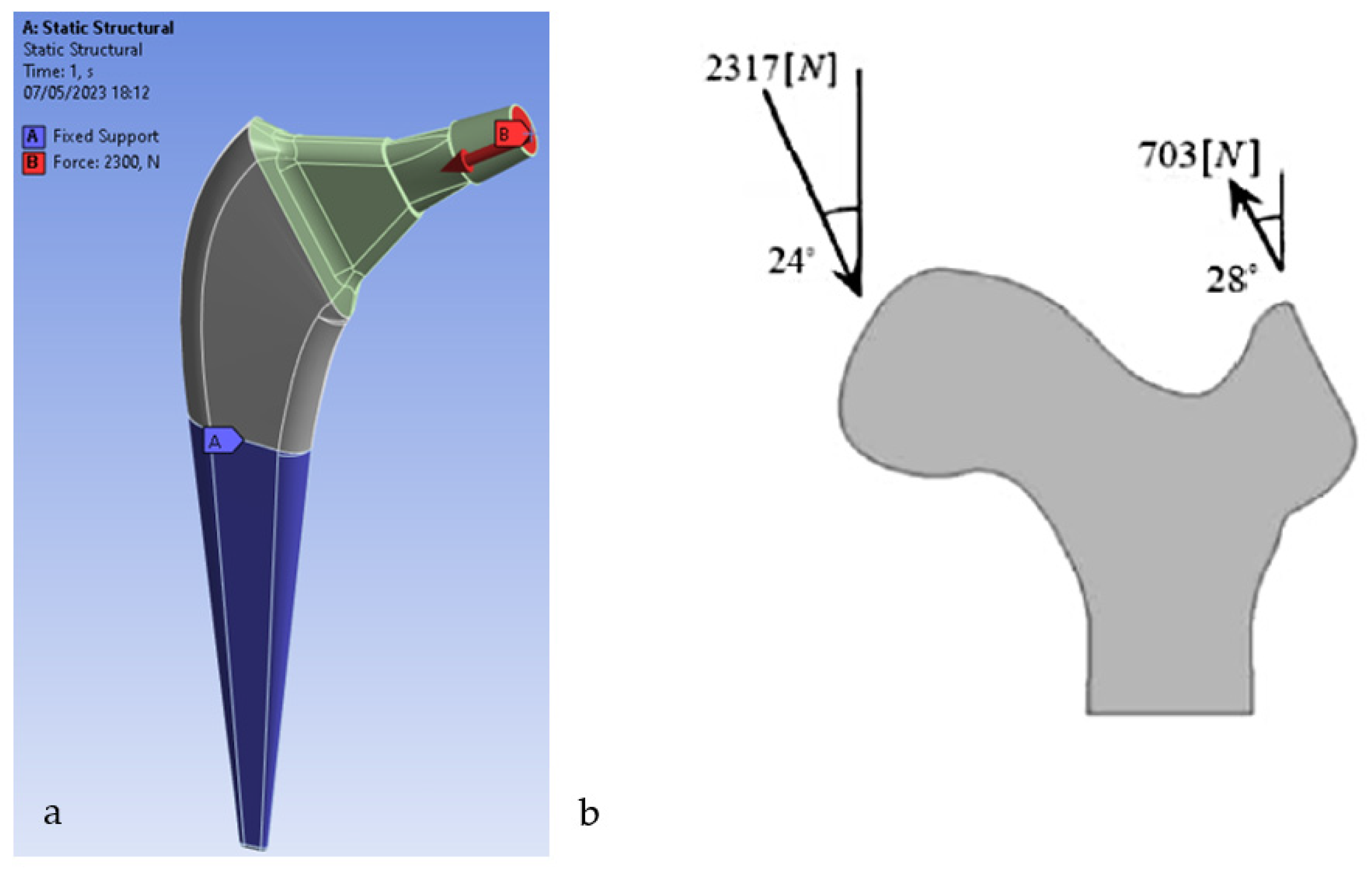
The boundary conditions involve the application of constraints and forces. This analysis is performed using boundary conditions according to ASTM F2996-13 [
21]. The constraint conditions in the design of a femoral prosthesis refer to the restrictions or constraints imposed on the prosthesis to ensure its stability and integration with the surrounding bone. These constraint conditions are determined by the type of implant and its anatomical location in the human body. [
24] The dynamic load of the average walk is applied to the femoral stem from which they were taken [
25]. In a further analysis, the load deriving from a monopodalic support is also considered [
26]. Any type of torsional, rotational and tensile force is not considered, and the distal end areas are kept fixed
Figure 4. For the analysis of homogeneous models with multiple material variations, the ANSYS FEA code is used as a tool to solve the finite element model.
3. Results
The distribution of tensions is one of the important information that can be obtained through the finite element analysis (FEM) of a femoral prosthesis. Von-Mises stress is one of the most common parameters used to assess the state of stress within a structure.
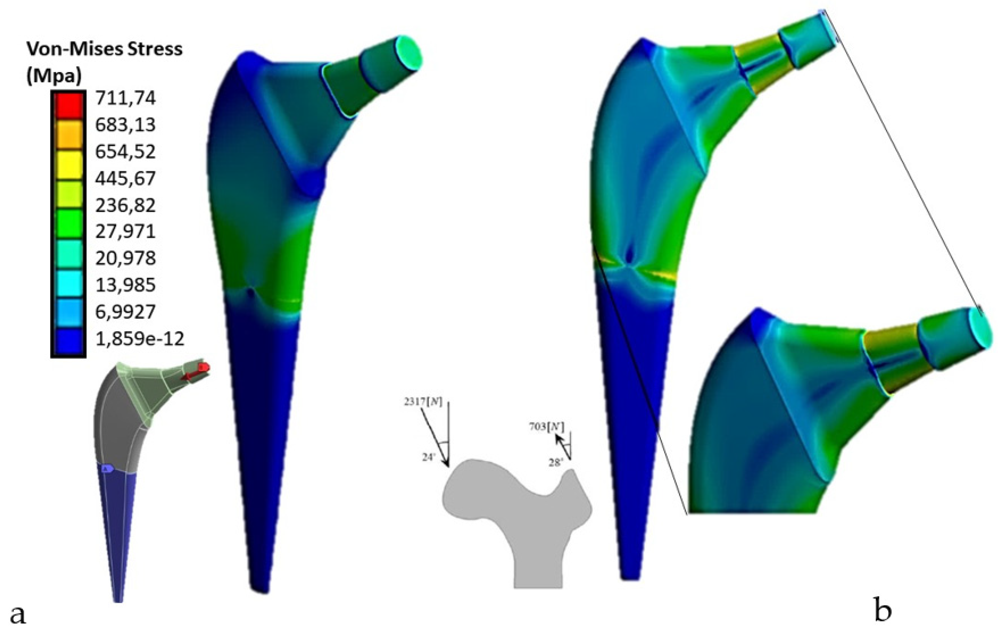
Von-Mises stress is a measure of equivalent stress that takes into account the main stresses in a particular region or component. This parameter considers the stresses in all directions and provides a unique value that represents the maximum equivalent stress in the analyzed region. The Von-Mises results for a femoral prosthesis can be represented through a color map or a graph showing the distribution of tension in the entire prosthesis or in specific regions of interest. Different colors can be used to indicate different levels of tension, allowing a visual assessment of high and low stress areas. The Von-Mises results are important because they help identify critical areas subject to high stress, which could be subject to potential failure or deformation. This information can be used to evaluate and optimize the design of the prosthesis, identifying areas that require further modification or reinforcement. For the applied load according to ASTM F2996-13, and that applied considering the mono-breech load,
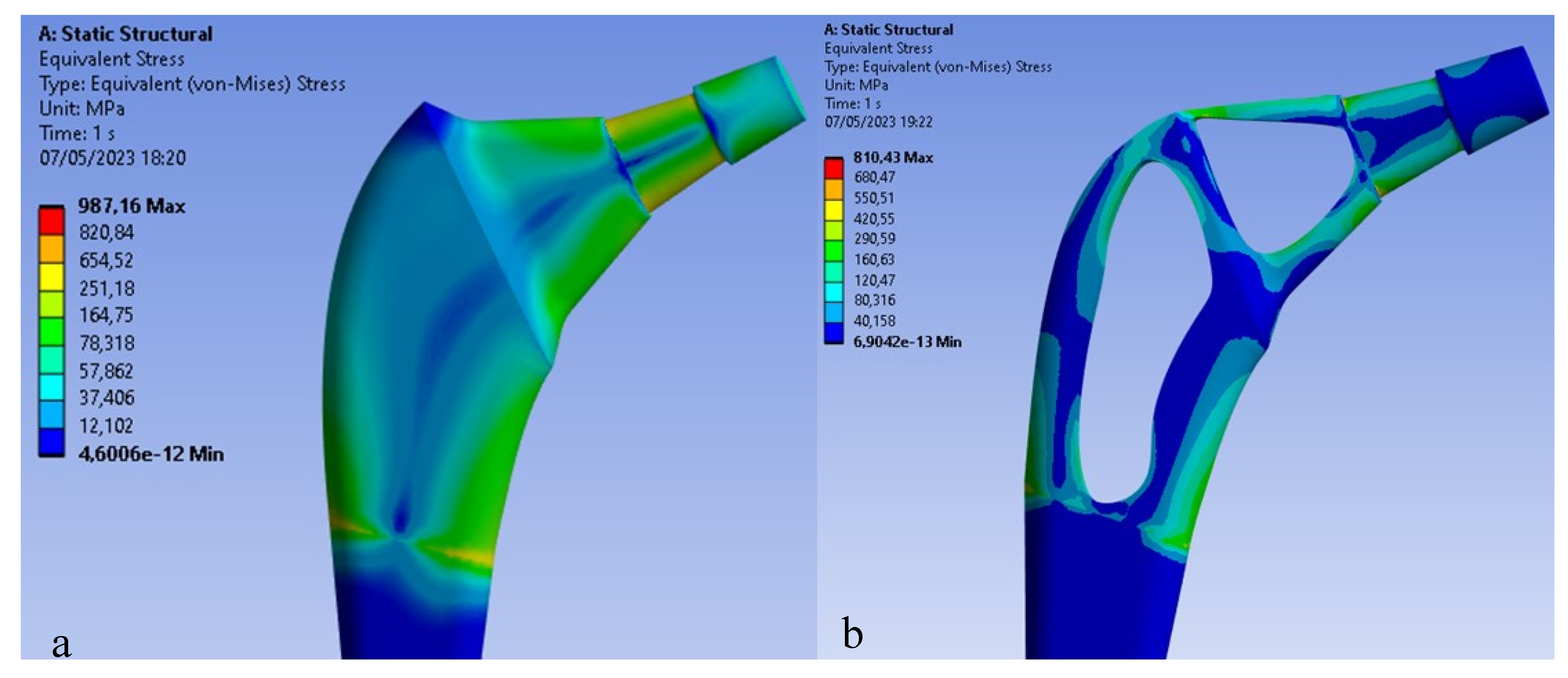
Figure 5 shows the Von Mises distribution on the titanium stem.
As can be seen in the first case, there are about 700 Mpa of stress on the upper area of the stem, compared to the second case in which about 987Mpa of stress are reached, a value higher than the breaking load of the material. Therefore, the mono-breech load condition is the most critical to which a femoral prosthesis can be subjected.
Topology optimization
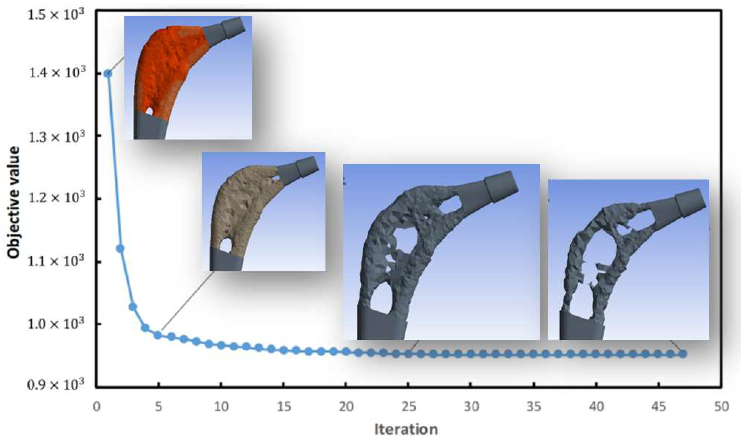
The goal was to reduce weight by at least 30%, to do this the ANSYS software based on the assigned constraint and load conditions and shape retention conditions on the implant neck and in the area of contact with the femur, performed 87 iterations
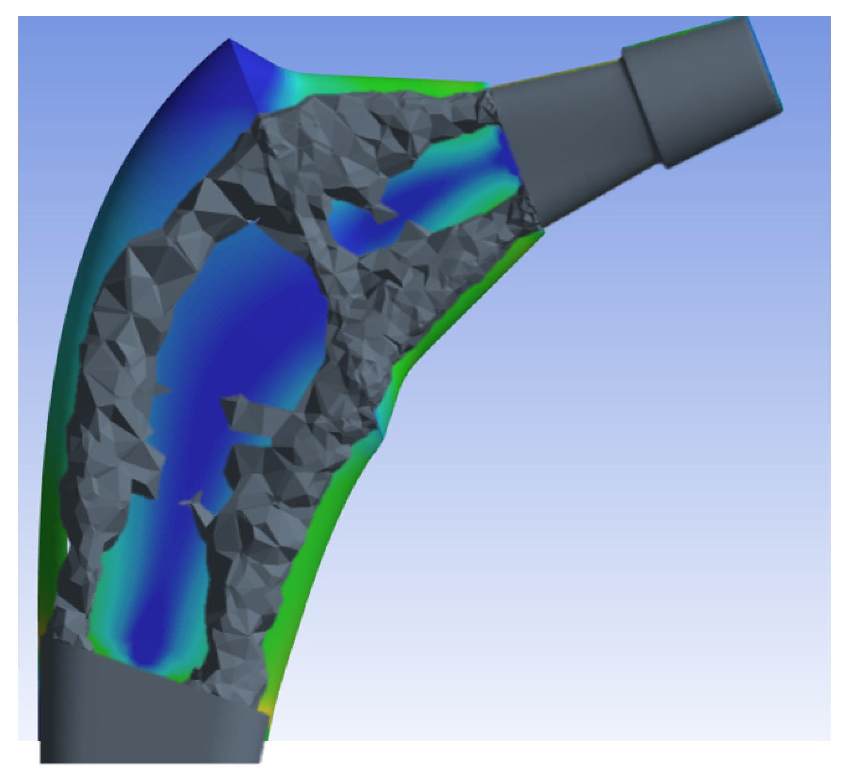
Figure 6 and eventually based on the maximum Von-Mises stresses created a topologically more efficient form
Figure 7.
Once the ANSYS finite element software resulted in the most topologically efficient form, the new geometry was simulated by performing a new mesh, leaving the mesh settings used for the previous prosthesis unchanged. It is subsequently under the same condition of constraint and monopodialic load studied previously we went to study the Von-Mises stress distribution comparing it with the full prosthesis
Figure 9.
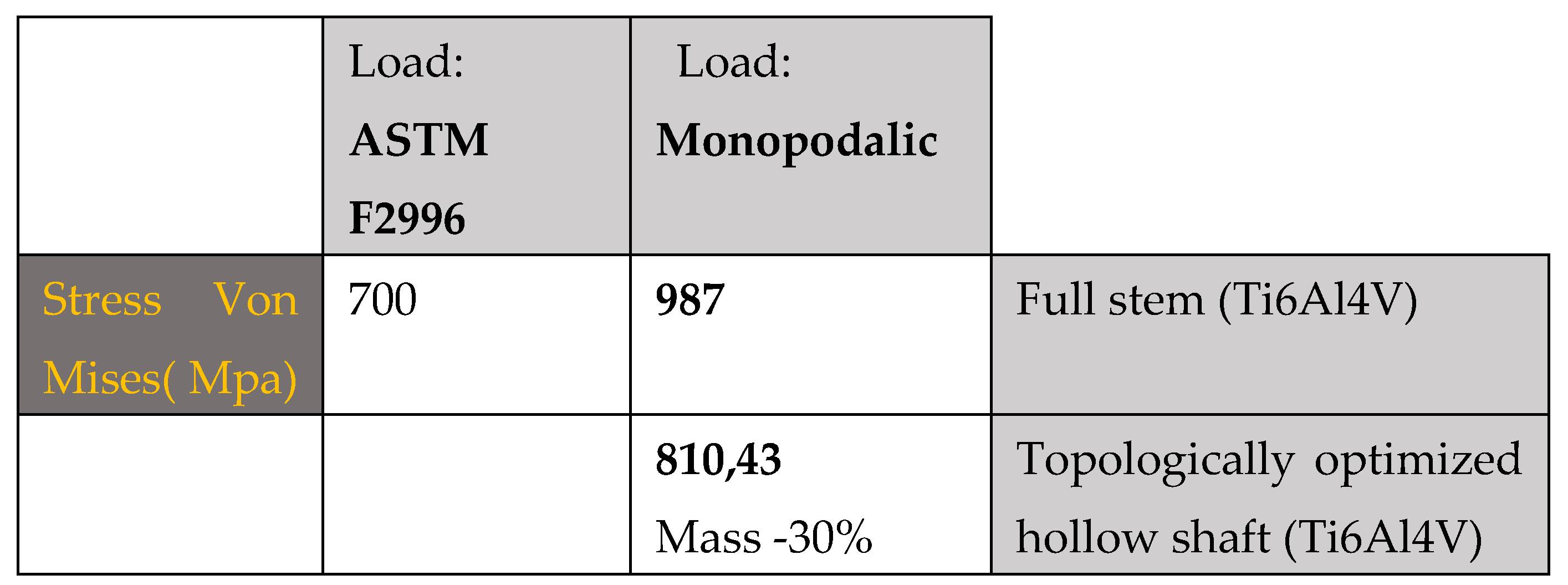
The results shown in
Figure 9 demonstrate how the topological optimization carried out on the same material (Titanium) led to a reduction in mass of 30% and the maximum stress went from 987 Mpa to about 810 Mpa value more than acceptable for the material.
Table 2.
summarizes the main results obtained from this first study.
Table 2.
summarizes the main results obtained from this first study.
The maximum tension as we can observe is concentrated on the areas that have a reduced section, in particular on the neck of the stem, stress values between 550 Mpa and 660 Mpa are reached. Because the yield stress is 800 Mpa we can say that there are no critical issues.
Reduction of Stress Shielding with carbon fiber prostheses.
As anticipated in the introduction, a potential solution to reduce bone loss associated with stress shielding is the use of implants with an overall reduction in flexion stiffness. In this regard, a femoral component manufactured from a CF composite with an intermediate polymer layer and a hydroxyapatite (HA) coating for cementless fixation was developed (
Figure 10).
Hydroxyapatite is the most documented calcium phosphate and can be used in bulk form, as a coating and/or cement [
27,
28]. This material can be classified according to its porosity, phase and processing method. It has excellent biocompatibility and is able to promote osteo-conduction and osseointegration. As a result of its excellent conductive and favorable bioactive properties, it is widely preferred as a biomaterial of choice in both dentistry and orthopedics [
29,
30]. While one of the advantages of carbon fiber is that it is biocompatible,[
34] promotes bone growth on the surface, has mechanical characteristics similar to cortical bone, in this way there is a reduction in stress shielding. Under the same constraint and load conditions shown in
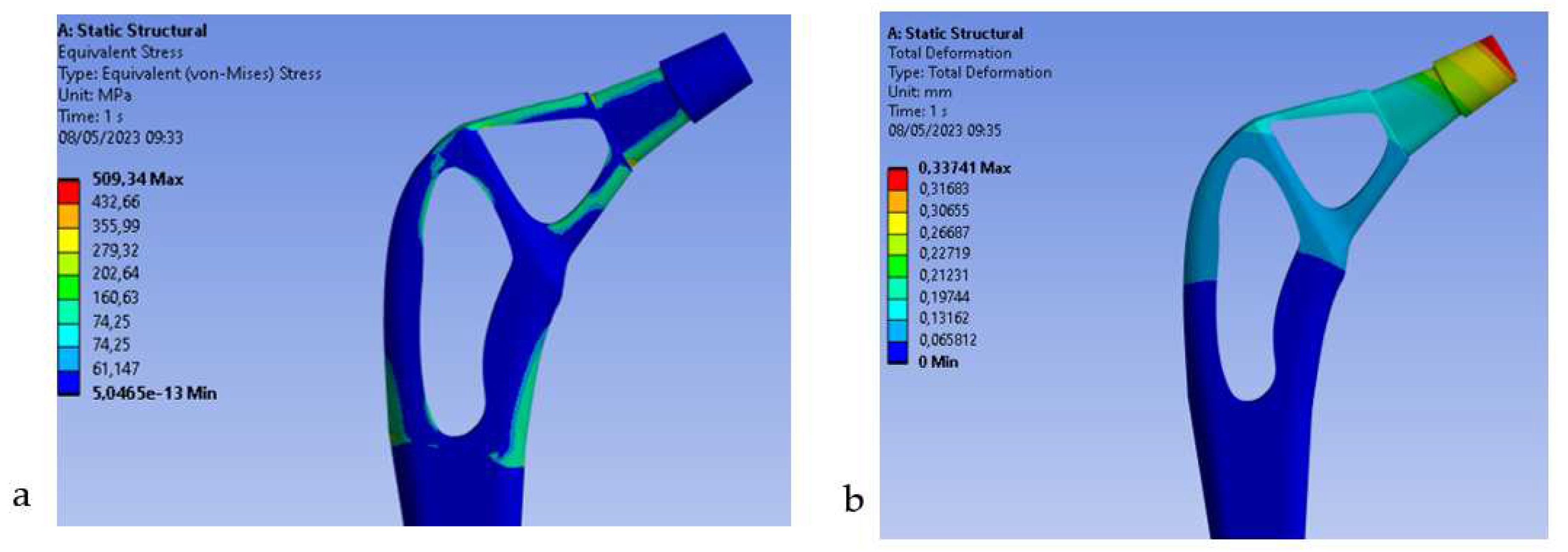
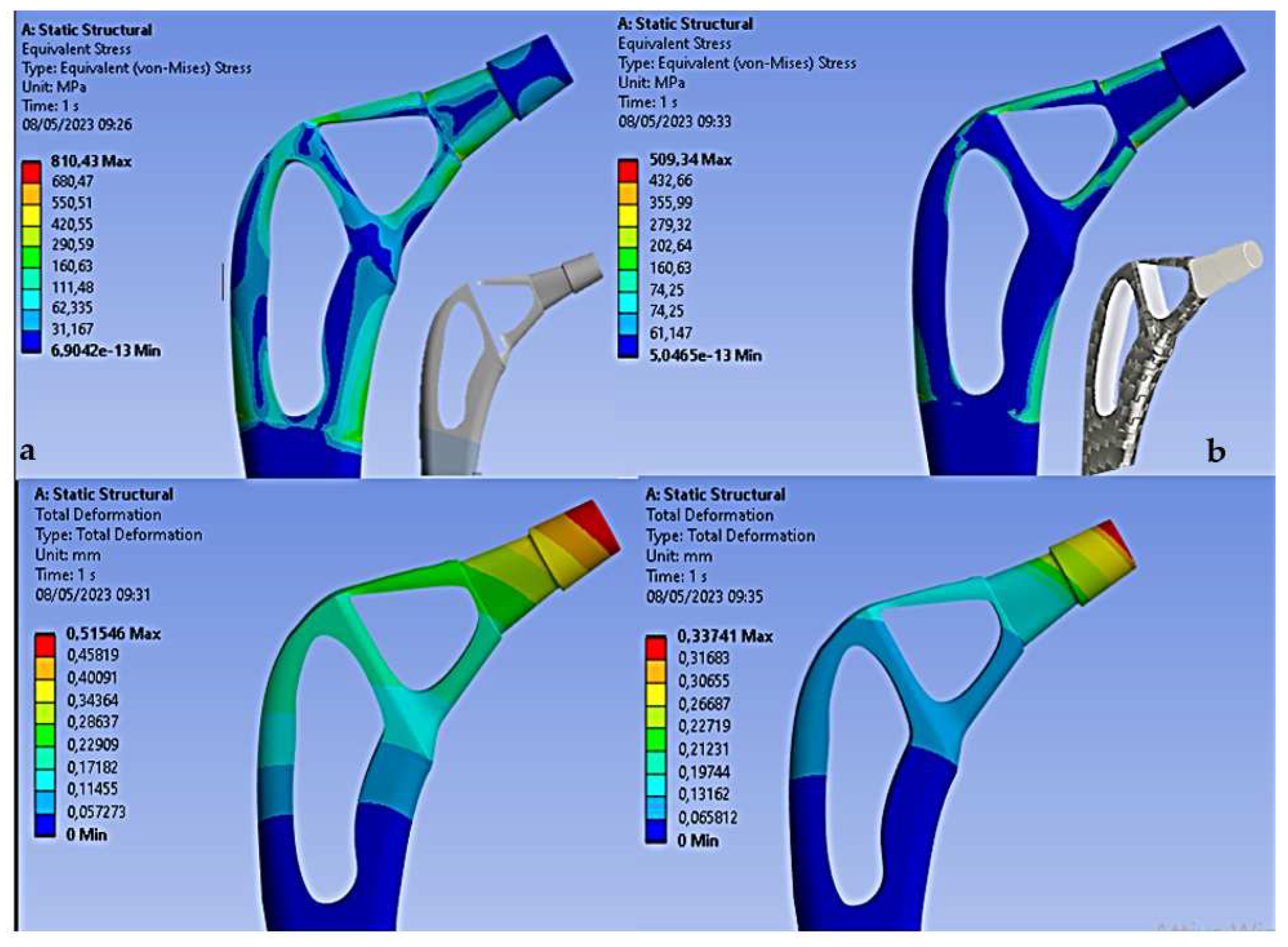
Figure 4b) the results on the Von-Mises stress distribution for the rod topologically optimized in composite material are reported.
Figure 11
From the results we can see how the use of carbon fiber allows to decrease the stress of Von Mises for the high mechanical strength of the fiber, in fact it goes from 810 Mpa (Titanium) to 509Mpa (Carbon), also the total deformation decreases from 0.51 mm (Titanium) to 0.33 mm (Carbon). Therefore, this decrease in both stress and deformation leads to an increase in stiffness of the entire stem with advantages on stress shielding.
4. Discussion
The most important finding of this study is that topological optimization can be used to design femoral and selectively hollowed out stems with higher compliance for less stress shielding. In the field of femoral prostheses, topological optimization can be used to design and optimize the shape and structure of the prosthesis itself. The goal of topological optimization in femoral prostheses is to reduce the weight of the prosthesis while maintaining its necessary strength and rigidity. [
35] This can result in lighter, more comfortable and more functional prostheses for patients. The topology optimization process typically involves several steps:
Definition of requirements: The desired performance requirements for the femoral prosthesis are defined, such as strength, stiffness and maximum permissible weight.
Creating a CAD Model: A computer-aided design (CAD) model of the prosthesis is created, representing its geometry and structure.
Enforcement of restrictions: The necessary restrictions and constraints are applied, such as physical space limits, location of holes for fixing screws, or other specific considerations.
Definition of the design region: The area in which the distribution of the material for the prosthesis can be varied is defined.
Application of optimization: Through topology optimization algorithms, different configurations are explored to determine the optimal distribution of the material. The goal is to reduce weight while maintaining the required performance.
Analysis and verification: Optimized configurations are analyzed through simulations or structural analysis to evaluate performance and feasibility.
Prosthesis realization: Once an optimized design is achieved, the prosthesis can be made using additive manufacturing technologies or other manufacturing methods.
Topological optimization can help improve the performance and efficiency of femoral prostheses, but it is important to emphasize that the process requires specialized skills and resources.
The use of carbon fiber composite material has allowed to obtain a further optimization since the composite having mechanical characteristics in terms of rigidity comparable to those of the bone, allows to further reduce the shielding of the stresses, also as shown in [
36] the carbon composite is biocompatible and the bone affixing on this material is 15% greater than the titanium alloy and the use of a hydroxyapatite coating It allows this percentage to be increased to 37% [
37]. Carbon fiber femoral prostheses offer several advantages over traditional metal prostheses. First, carbon fiber is lightweight, which means the prosthesis will weigh less than a metal prosthesis. This can help reduce the load on the rest of the limb and improve patient mobility. In fact, thanks to their combination of lightness and strength, carbon fiber femoral prostheses can reduce stress and pressure exerted on the surrounding bone. This can help prevent bone deterioration, reduce the risk of stress fractures, and improve bone integration with the denture. Lower risk of corrosion: Unlike metal alloy dentures, carbon fiber femoral dentures are not subject to corrosion. This means that they will not corrode or damage over time due to corrosive processes. This can contribute to longer life of the prosthesis and reduce the need for revision surgery. Possibility of customization: Carbon fiber is a highly moldable and adaptable material, which allows the realization of highly personalized femoral prostheses. Carbon fiber prostheses can be designed to adapt to the specific anatomical and functional needs of the patient, ensuring better adaptation and better performance. In addition, carbon fiber is a rigid and durable material, which allows you to make thinner and less invasive dentures. This means that the prosthesis can be implanted with less surgical invasiveness and that the patient can benefit from faster rehabilitation. Carbon fiber femoral prostheses are designed to anatomically adapt to the shape of the femur, providing greater stability and better coupling with the surrounding bone. This can help reduce the risk of complications such as unscrewing or sagging the denture. However, it is important to note that the use of carbon fiber femoral implants may not be indicated for all patients. The choice of the prosthesis depends on several factors, such as the general state of health of the patient, age, level of physical activity and the specific condition of the femur to be replaced. The coating adopted for the hydroxyapatite carbon prosthesis is widely used as a coating in femoral prostheses to promote osseointegration, i.e., the process of fusion of the prosthesis with the surrounding bone. [
38,
39,
40,
41,
42]
The hydroxyapatite coating on the surface of femoral prostheses offers several advantages:
Better osseointegration: Hydroxyapatite creates a biocompatible interface between the bone and the prosthesis, facilitating the adhesion and growth of bone cells. This promotes the formation of a solid bond between the prosthesis and the surrounding bone, reducing the risk of developing complications such as sagging or relaxation of the prosthesis.
Stimulation of bone regeneration: Hydroxyapatite can help stimulate bone regeneration due to its structural similarity to natural bone tissue. It promotes the deposition of new bone tissue around the prosthesis, increasing the stability and durability of the implant.
Reduction of inflammation and infection: The hydroxyapatite coating can help reduce inflammation and the risk of infection. Its biocompatible surface reduces the unwanted immune response and can hinder bacterial adhesion to the surface of the prosthesis.
Improvement of mechanical properties: Hydroxyapatite can also improve the mechanical properties of the femoral prosthesis. By acting as a durable coating layer, it can help reduce wear and abrasion of the prosthesis, prolonging its durability.
Importantly, hydroxyapatite coating can be applied in different forms, such as porous coatings, spray coatings or electrochemical coatings. The choice of method depends on the specifics of the prosthesis and the preferences of the orthopedic surgeon. [
43].
5. Conclusions
In conclusion, a topological optimization process was developed and applied to the design of the femoral stem, which included a modification of the geometry as a function of the Von-Mises stress distribution and a variation on the material opting, for a composite material that as already shown in various studies offers histological characteristics that make it implantable. This optimization carried out on two roads has made it possible to solve a problem that leads to the failure of the plants or stress shielding, a phenomenon that occurs when the component inserted in the bone has a different stiffness and therefore the distribution of stresses is not distributed evenly to the bone implant interface but, Tension concentrations lead to inflammatory phenomena on the bone reducing its ability to create optimal osseointegration. The main results obtained in this study are reported in terms of Von-Mises voltage.
Stress di Von-Mises
Femoral stem in Titanium alloy: 987 Mpa
Optimized Titanium alloy femoral stem: 810 Mpa
Femoral stem in composite material: 509 Mpa
Finite element analysis (FEM) used in such a study is a numerical technique that is often used to evaluate the structural behavior of femoral prostheses. The objective of FEM analysis is to simulate the behavior of the prosthesis and evaluate its performance, subjecting it to realistic loads and conditions of use. Importantly, FEM analysis is an important engineering tool for the design and optimization of femoral prostheses. FEM analysis can be used to test and compare different prosthesis design configurations, allowing you to identify which option offers the best performance in terms of strength, stiffness, weight and other characteristics. This helps engineers and surgeons select and optimize the design that best suits the patient's needs. However, like any research method, FEA may have some limitations. Some of the common limitations of FEA studies include:
Simplified intake: FEA relies on several assumptions to simplify the model and make computationally feasible analysis. These assumptions may include linearity of materials, absence of plastic deformation phenomena and negligibility of dynamic factors. Such simplifications can affect the accuracy of the results and the realistic representation of the real behavior of the system. Material parameters: FEA requires the assignment of material parameters to model components. However, obtaining accurate and representative material data for the materials used in femoral prostheses can be complex and subject to change. The accuracy of material parameters can affect FEA results.
Boundary conditions: The boundary conditions specified in the FEA can greatly affect the analysis results. Choosing appropriate and realistic boundary conditions is essential to achieve valid results. However, accurate determination of boundary conditions can be difficult and can introduce a margin of error.
Mesh accuracy: Mesh, which is the division of the model into finite elements, can affect the accuracy of FEA results. A mesh that is too coarse may not accurately capture the detailed behavior of the system, while a mesh that is too fine may require considerable computational resources. The choice of mesh size and density is a trade-off between precision and computational cost.
Experimental validation: Although FEA is a powerful analytical tool, it is important to remember that FEA results must be validated experimentally to ensure the reliability of the results. The lack of valid experimental validation may limit confidence in the results obtained through the FEA.
It is important to consider these limitations and interpret the results of the FEA with caution, taking into account the context. However, the interpretation of FEM analysis results requires appropriate technical and clinical expertise. It is essential that a qualified professional, such as a biomedical engineer or orthopedic surgeon, uses and interprets the results of FEM analysis to make informed decisions about the design and use of femoral prostheses. [
30,
31,
32,
34]. A further study could predict the influence of dynamic load and therefore of the finite element evaluation of the fatigue behavior of the stem. In addition, bone implant contact has not been modeled, which could lead to more detailed information about the distribution of stress within the bone.
Author Contributions
Conceptualization, M.C. and B.T.; methodology, M.C.; software, M.C.; validation, B.T., G.S. formal analysis, M.C. and B.T.; investigation, M.C.; resources, M.C. and B.T.; data curation,M.C.; writing—original draft preparation, M.C. and B.T.; writing—review and editing,M.C, B.T, G.S, G.G..; visualization, B.T, G.S..; supervision, G.S. and B.T.; project administration, G.S. and B.T. All authors have read and agreed to the published version of the manuscript.
Funding
This research received no external funding
Institutional Review Board Statement
Not applicable.
Informed Consent Statement
Not applicable.
Data Availability Statement
All experimental data to support the findings of this study are available contacting the corresponding author upon request.
Conflicts of Interest
The authors declare no conflict of interest.
References
- Sharkey PF, Austin MS, Hozack W. Total hip arthroplasty in the young patient. Instr Course Lect 2006;55:173–176.
- Roder C, Parvizi J, Eggli S, Berry DJ, Muller ME, Busato A. Demographic factors affecting long-term outcome of total hip arthroplasty. Clin Orthop Relat Res 2003;417:62 73.
- Berry, DJ. Management of periprosthetic fractures: The hip. J Arthroplasty 2002;17(Suppl 1):11–13.
- Herberts P, Malchau H. Long-term registration has improved the quality of hip replacement. Acta Orthop Scand 2000;71:111–121.
- Furnes O, Lie SA, Espehaug B, Vollset SE, Engesaeter LB, Havelin LI. Hip disease and the prognosis of total hip replacements. A review of 53 698 primary total hip replacements reported to the Norwegian Arthroplasty Register 1987–99. J Bone Joint Surg Br 2001;83:579–586.
- Campbell M, Bureau MN, Yahia L. Performance of CF/PA12 composite femoral stems. J Mater Sci Mater Med 2008;19:683–693.
- Auclair-Daigle C, Bureau MN, Legoux JG, Yahia L. Bioactive hydroxyapatite coatings on polymer composites for orthopedic implants. J Biomed Mater Res A 2005;73:398–408.
- Callister,W. D. Materials Science and Engineering, 4th ed.; John Wiley & Sons: New York, NY, USA, 1997. [Google Scholar]
- Peters, S.T. Handbook of Composites, 2nd ed.; Chapman and Hall: New York, NY, USA, 1998. [Google Scholar]
- Ali, M.S.; French, T.A.; Hastings, G.W.; Rae, T.; Rushton, N.; Ross, E.R.S.; Wynn-Jones, C.H. Carbon fibre composite bone plates. J. Bone Jt. Surg. 1990, 72, 586–591. [Google Scholar] [CrossRef] [PubMed]
- Tarallo, L.; Mugnai, R.; Adani, R.; Zambianchi, F.; Catani, F. A new volar plate made of carbon-fiber-reinforced polyetheretherketon for distal radius fracture: Analysis of 40 cases. J. Orthop. Traumatol. 2014, 15, 277–283.
- Blazewicz, M. Carbon materials in the treatment of soft and hard tissue injuries. Eur. Cells Mater. 2001, 2, 21–29. [Google Scholar] [CrossRef] [PubMed]
- Pilliar, R.M.; Blackwell, R.; Macnab, I.; Cameron, H.U. Carbon fiber-reinforced bone cement in orthopedic surgery. J. Biomed. Mater. Res. 1976, 10, 893–906 [CrossRef] [PubMed]. [Google Scholar] [CrossRef] [PubMed]
- Antoniac, I. Biologically Responsive Biomaterials for Tissue Engineering; Springer: New York, NY, USA, 2013; pp. 173–199. [Google Scholar]
- Balasubramanian, M. Composite Materials and Processing; CRC Press Taylor & Francis Group: Boca Raton, FL, USA, 2014; pp. 31–82. [Google Scholar]
- Park, J.B.; Lakes, R.S. Hard Tissue Replacement. In Biomaterials an Introduction, 2nd ed.; Plenum Press: New York, NY, USA, 1992; p. 347. [Google Scholar]
- Guitchounts, G.; Markowitz, J.E. ; Liberti,W.A.; Gardner, T.J.A. Carbon-fiber electrode array for long-term neural recording. J. Neural Eng. 2013, 10.
- Mendes, D.G.; Angel, D.; Grishkan, A.; Boss, J. Histological response to carbon fibre. J. Bone Jt. Surg. 1985, 67, 645–649. [Google Scholar] [CrossRef] [PubMed]
- Ratner, B.D.; Hoffman, A.S.; Schoen, F.J.; Lemons, J.E. Composites. In Biomaterials Science, 2nd ed.; Elsevier: San Diego, CA, USA, 2004; p. 183. [Google Scholar]
- Stout, D.A.; Basu, B.; Webster, T.J. Poly(lactic-co-glycolic acid): Carbon nanofiber composites for myocardial tissue engineering applications. Acta Biomater. 2011, 7, 3101–3112.
- American Society for Testing and Materials, ‘‘ASTM F1612– 95’’, Standard Practice for Cyclic Fatigue
Testing of Metallic Stemmed Hip Arthroplasty Femoral Components with Torsion.
- Petersen, R.C. Bisphenyl-Polymer/Carbon-Fiber-Reinforced Composite Compared to Titanium Alloy Bone Implant. Int. J. Polym. Sci. 2011, 2011.
- G. Kharmanda, I. Antypas, A. Dyachenko, International Journal of Mechanical Engineering and
Technology 10(9), 1-11 (2019).
- S.A. Shaik, K. Bose, H.P. Cherukuri, Materials and Design 42, 230–237 (2012).
- M. Fraldi, L. Esposito, G. Perrella, A. Cutolo, S.C. Cowin, Biomech Model Mechanobiol 9, 389–402 (2010).
- G. Kharmanda, Computer Methods in Biomechanics and Biomedical Engineering 19(14), 1557-1566 (2016).
- W. L. Jaffe and D. F. Scott, “Current concepts review: total hip arthroplasty with hydroxyapatite-coated
prostheses,” Journal of Bone and Joint Surgery A, vol. 78, no. 12, pp. 1918–1934, 1996.
- J. Z. Yang, R. Sultana, X. Z. Hu, and P. Ichim, “Novel layered hydroxyapatite/tri-calcium phosphatezirconia
scaffold composite with high bending strength for load-bearing bone implant application,”
International Jounal of Applied Ceramic Teconology, 2013.
- R. J. B. Sakkers, R. A. J. Dalmeyer, R. Brand, P. M. Rozing, and C. A. van Blitterswijk, “Assessment of bioactivity for orthopedic coatings in a gap-healing model,” Journal of Biomedical Materials Research, vol. 36, pp. 265–273, 1997.
- B. C. Mendelson, S. R. Jacobson, A. M. Lavoipierre, and R. J. Huggins, “The fate of porous hydroxyapatite granules used in facial skeletal augmentation,” Aesthetic Plastic Surgery, vol. 34, no. 4, pp. 455–461, 2010.
- E. O.Martz, V. K. Goel, M. H. Pope, and J. B. Park, “Materials and design of spinal implants—a review,”
Journal of Biomedical Materials Research, vol. 38, pp. 267–288, 1997.
- J.W. Choi, Y.M. Kong, H. E. Kim, and I. S. Lee, “Reinforcement of hydroxyapatite bioceramic by addition of Ni3Al and Al2O3,” Journal of the American Ceramic Society, vol. 81, no. 7, pp. 1743– 1748, 1998.
- V. V. Silva, F. S. Lameiras, and R. Z. Domingues, “Microstructural and mechanical study of zirconia-hydroxyapatite (ZH)n composite ceramics for biomedical applications,” Composites Science and Technology, vol. 61, no. 2, pp. 301–310, 2001.
- Performance of CF/PA12 composite femoral stems Melissa Campbell, Martin N. Bureau L’Hocine Yahia, J Mater Sci: Mater Med (2008) 19:683–693.
- Campbell M, Bureau MN, Yahia L. Performance of CF/PA12 composite femoral stems. J Mater Sci Mater Med 2008;19:683–693.
- Dimitrievska S, Whitfield J, Hacking SA, Bureau MN. Novel carbon fiber composite for hip replacement with improved in vitro and in vivo osseointegration. J Biomed Mater Res A 2009;91: 37–51.
- B. Pal, S. Gupta, Influence of the change in stem length on the load transfer and bone remodelling for a cemented resurfaced femur, J. Biomech. 43 (15) (2010) 2908–2914.
- D. Kluess, H. Martin, Influence of femoral head size on impingement, dislocation and stress distribution in total hip replacement, Med. Eng. Phys. 29 (4) (2007) 465–471.
- H.F. El’Sheikh, B.J. MacDonald, Finite element simulation of the hip joint during stumbling: a comparison between static and dynamic loading, J. Mater. Process. Technol. 143–144 (2003) 249–255.
- Y. Li, C. Yang, H. Zhao, S. Qu, X. Li, Y. Li, New Developments of Ti-Based Alloys for Biomedical Applications, Materials. 7 (3) (2014) 1709–1800.
- D. Bennett, T. Goswami, Finite element analysis of hip stem designs, Mater. Des. 29 (1) (2008) 45–60.
- Y.S. Lai, H.W. Wei, T.K. Chang, C.K. Cheng, the effects of femoral canal geometries, stem shapes, cement thickness, and stem materials on the choice of femoral implant in cemented total hip replacement, J. Chinese Instit. Eng. 32 (3) (2009) 333–341.
- C. Dopico-Gonzalez, A.M. New, M. Browne, Probabilistic finite element analysis of the uncemented hip replacement effect of femur characteristics and implant design geometry, J. Biomech.
|
Disclaimer/Publisher’s Note: The statements, opinions and data contained in all publications are solely those of the individual author(s) and contributor(s) and not of MDPI and/or the editor(s). MDPI and/or the editor(s) disclaim responsibility for any injury to people or property resulting from any ideas, methods, instructions or products referred to in the content. |
© 2023 by the authors. Licensee MDPI, Basel, Switzerland. This article is an open access article distributed under the terms and conditions of the Creative Commons Attribution (CC BY) license (http://creativecommons.org/licenses/by/4.0/).
