Submitted:
13 July 2023
Posted:
14 July 2023
You are already at the latest version
Abstract
Keywords:
1. Introduction
2. Materials and Methods
3. Theoretical Background
3.1. Heating with a Volume Heat Source
3.2. Heating with a Surface Heat Source
4. Results
5. Discussion
6. Conclusions
- Based on the proposed complex γ heating type criterion, PEBs have been ranked for better understanding both the nature of the thermal processes occurring under irradiation and for predicting their suitability for certain applications. The γ heating type criterion is called complex because it depends not only on the parameters of PEBs, but also on the target material.
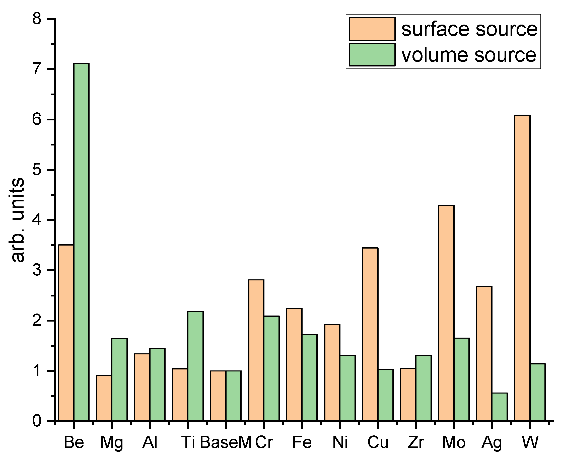
- It has been shown that the most refractory of the considered materials are W, Mo, Be and Be, Ti, Mg in the case of pulsed surface and volume heating, respectively. However, Ti and Mg are simultaneously the most fusible ones in pulsed surface heating.
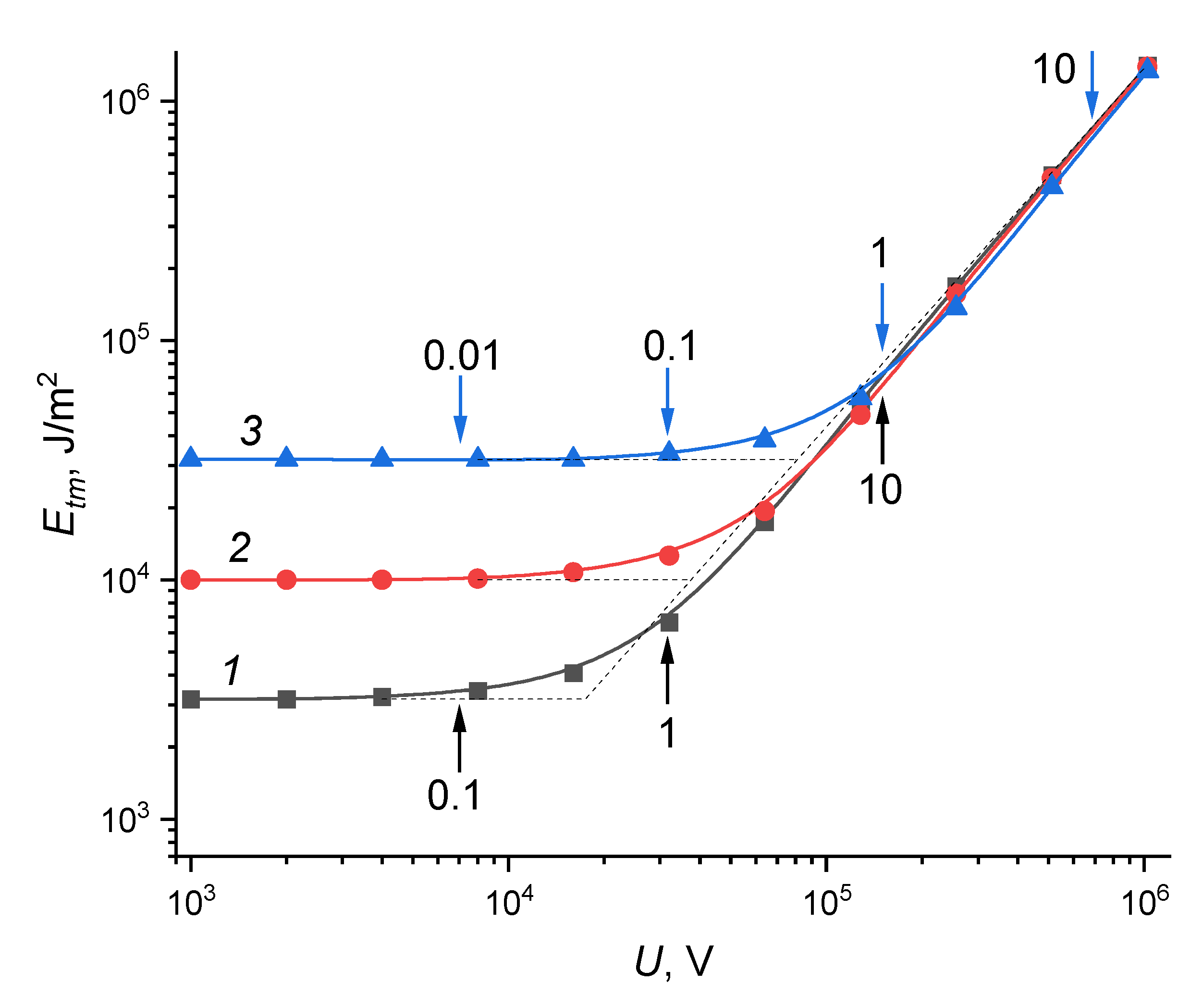
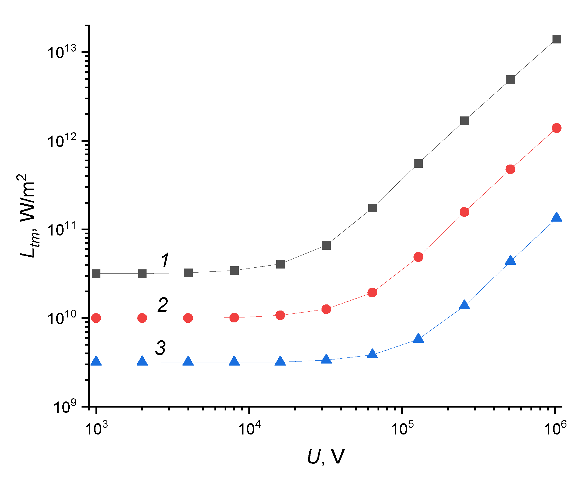
- Both MMT and EMMT have been calculated over the wide ranges of U accelerating voltages and τ pulse durations. At low U levels (γ≪1), EMMT increases with rising the τ pulse duration. The longer the τ pulse duration, the more energy is transmitted into a target bulk and the more it needs to be input to the surface layer. At high U levels (γ≫1), heat removal into the target bulk does not occur. Therefore, only the fact of accumulation of a given amount of energy becomes important, regardless of the τ pulse duration.
- It was established that to calculate MMT and EMMT for any both materials and PEBs, it is sufficient to use analytical formulas (26) and (25) and interpolate the data within the γ∊[0.1;1] interval.
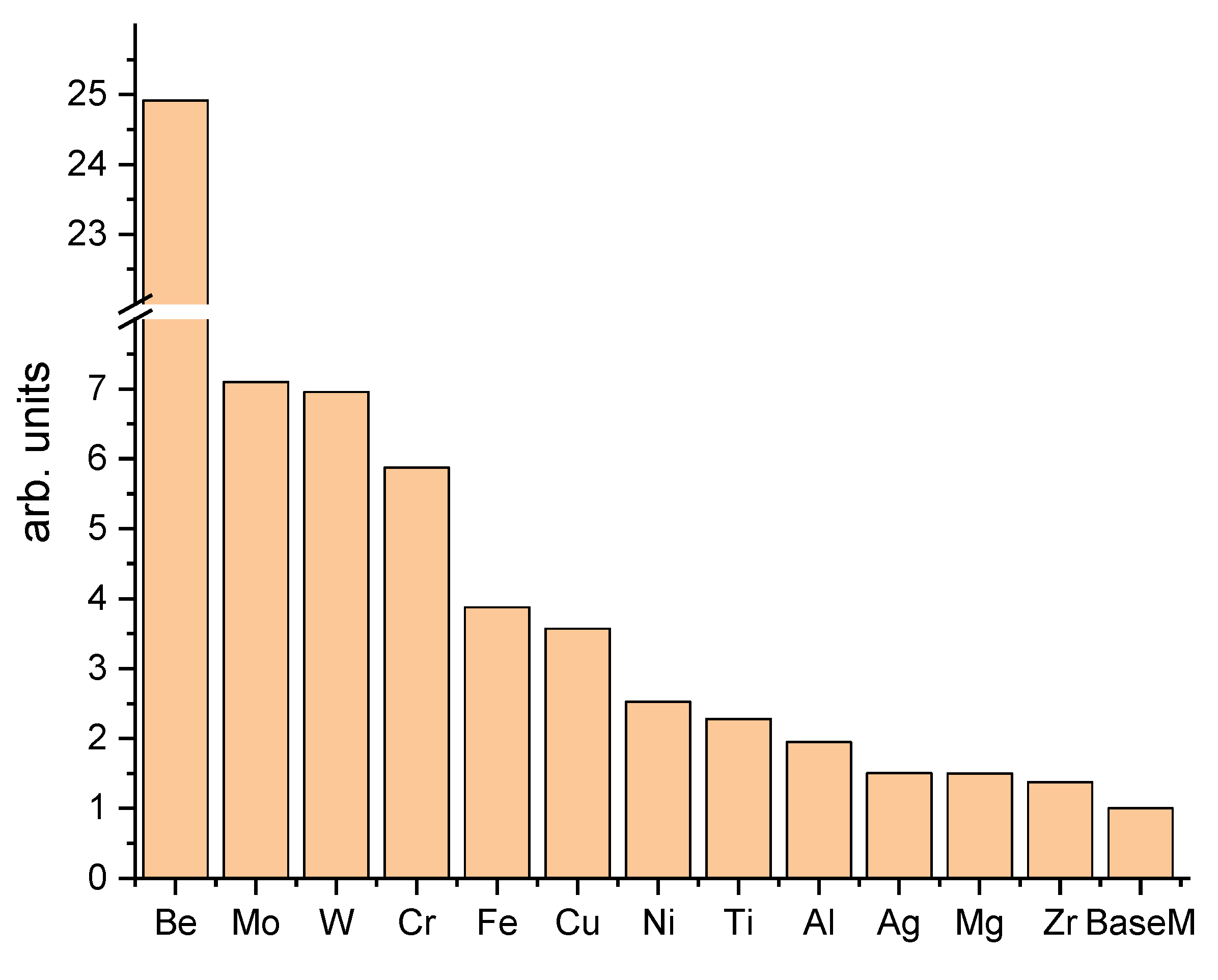
- The general refractoriness series of metals is ranked for pulsed heating processes. It classifies metals not only in terms of the complexity of their heating up to the melting points, but also by their ability to accumulate heat under irradiation.
- Be is the unique refractory material in pulsed heating processes. It can absorb a relatively large amount of heat without a noticeable rise in temperature. The closest ones are Mo, W, and Cr, which are significantly (by 3.5–4.2 times) inferior in this respect.
- The temperature distribution profile in a target under irradiation with PEBs, normalized to the electron range, does not depend on the density of the target material in the case of a volume heat source. The reason is the mutual compensation of two opposite tendencies. On the one hand, the specific density of nuclei increases in direct proportion to the substance density, and temperature should reduce at a fixed energy. On the other hand, the energy release volume decreases due to the inversely proportional relationship between the electron range and the substance density, and temperature should increase.
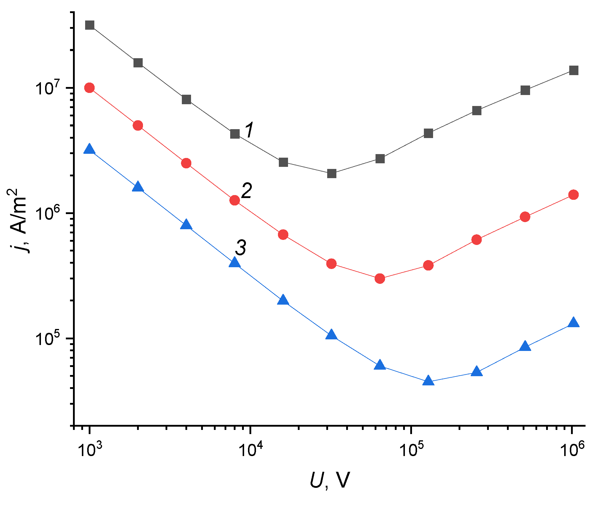
- The CVDs have been calculated, which can be considered as practical guidelines for determining the j current densities that provide MMT at a given U accelerating voltage.
- Some conclusions can be drawn about the nature of the occurring thermal processes inside the target, observing only the CVD behavior, without any data on material thermophysical properties. Namely, when the left side of CVDs deviates from direct proportionality, the heat source ceases to be surface and becomes mixed. Moreover, the heat source can be considered volume, when it passes through the ∂j/∂U=0 point.
Author Contributions
Funding
Acknowledgments
Conflicts of Interest
References
- Koval’, N.N.; Ivanov, Y.F. Nanostructuring of surfaces of metalloceramic and ceramic materials by electron-beams. Russian Physics Journal 2008, 51, 505–516. [Google Scholar] [CrossRef]
- Koval, N.N.; Koval, T.V.; Krysina, O.V.; Ivanov, Y.F.; Teresov, A.D.; Moskvin, P.V.; Tran, M.K.A.; Prokopenko, N.A.; Petrikova, E.A. Experimental Study and Mathematical Modeling of the Processes Occurring in ZrN Coating/Silumin Substrate Systems under Pulsed Electron Beam Irradiation. Coatings 2021, 11, 1461. [Google Scholar] [CrossRef]
- Krysina, O.V.; Teresov, A.D.; Moskvin, P.V.; Koval, N.N.; Ivanov, Yu. F.; Akhmadeev, Yu. H.; Lopatin I., V. Variation in the Local Material Temperature During Electron Beam Treatment and its Influence on the Modified Layer Properties. Russian Physics Journal 2019, 62, 1139–1146. [Google Scholar] [CrossRef]
- Geng, Y.; Chen, X.; Konovalov, S.; Panchenko, I.; Ivanov, Yu.; Deev, V.; Prusov, E. Ultrafast microstructure modification by pulsed electron beam to enhance surface performance. Surface and Coatings Technology 2022, 434, 128226. [Google Scholar] [CrossRef]
- Gromov, V.E.; Konovalov, S.V.; Ivanov, Yu.F.; Shliarova, Yu.A.; Vorobyov, S.V.; Semin, A.P. Structure and properties of the CrMnFeCoNi high-entropy alloy irradiated with a pulsed electron beam. Journal of Materials Research and Technology 2022, 19, 4258–4269. [Google Scholar] [CrossRef]
- Ozur, G.E.; Proskurovsky, D.I. Generation of Low-Energy High-Current Electron Beams in Plasma-Anode Electron Guns. Plasma Phys. Rep. 2018, 44, 18–39. [Google Scholar] [CrossRef]
- Ozur, G.; Proskurovsky, D.; Rotshyein, V.; Markov, A. Production and application of low-energy, high-current electron beams. Laser and Particle Beams 2003, 21, 157–174. [Google Scholar] [CrossRef]
- Markov, A.; Yakovlev, E.; Petrov, V. Formation of Surface Alloys With a Low-Energy High-Current Electron Beam for Improving High-Voltage Hold-Off of Copper Electrodes. IEEE Transactions on Plasma Science 2013, 41, 2177–2182. [Google Scholar] [CrossRef]
- Dong, C; Wu, A.; Hao, S.; Zou, J.; Liu, Z.; Zhong, P.; Zhang, A.; Xu, T.; Chen, J.; Xu, J.; Liu, Q.; Zhou, Z. Surface treatment by high current pulsed electron beam. Surface and Coatings Technology 2003, 163–164, 620–624. [Google Scholar] [CrossRef]
- Liu, S.; Fu, J.; Shen, X.; Chen, B.; Han, X. Improved wear resistance of cemented carbide impact needle under high frequency micro-amplitude impact treated by high current pulsed electron beam. Wear 2023, 518–519, 204632. [Google Scholar] [CrossRef]
- Tian, N.; Guan, J.; Zhang, C.; Lyu, P.; Peng, C.; Cai, J.; Guan, Q. Influence of high-current pulsed electron beam irradiation on element diffusion behavior and mechanical properties of TC4/304 stainless steel diffusion bonded joints. Materials Characterization 2023, 198, 112713. [Google Scholar] [CrossRef]
- Lu, J.; Sui, X.; Yang, B.; Chen, J.; Cai, L.; Zhou, S.; Li, W.; Jiang, M.; Hao, S. Ultrafast in-situ transformation of graphite into graphene nanosheets by high current pulsed electron beam direct irradiation. Applied Surface Science 2022, 572, 151498. [Google Scholar] [CrossRef]
- Fedorov, S. V.; Kozochkin, M.; Stebulyanin, M. Control of the surface electron-beam alloying process by vibration monitoring Sergey. Mechanics & Industry 2018, 19, 702. [Google Scholar] [CrossRef]
- Fedorov, S.V.; Pavlov, M.D.; Okunkova, A.A. Effect of structural and phase transformations in alloyed subsurface layer of hard-alloy tools on their wear resistance during cutting of high-temperature alloys. J. Frict. Wear 2013, 34, 190–198. [Google Scholar] [CrossRef]
- Fedorov, S.V.; Aleshin, S.V.; Swe, M.H.; Abdirova, R.; Kapitanov, A.; Egorov, S. Comprehensive surface treatment of high-speed steel tool. Mechanics & Industry 2017, 18, 711. [Google Scholar] [CrossRef]
- Meisner, S.N.; Vlasov, I.V.; Yakovlev, E.V.; Panin, S.V.; Meisner, L.L.; D’yachenko, F.A. Impact of electron beam surface modification on deformation behavior and fracture properties of TiNi shape memory alloy. Materials Science and Engineering: A 2019, 740–741, 381–389. [Google Scholar] [CrossRef]
- Morini, F.; Bestetti, M; Franz, S.; Vicenzo, A.; Markov, A.; Yakovlev, E. Surface properties modification of magnesium alloys by low energy high current pulsed electron beam. Surface and Coatings Technology 2021, 420, 127351. [Google Scholar] [CrossRef]
- Yakovlev, E.; Pesterev, E.; Petrov, V.; Maznoy, A. Preparation of Al-Dy core-shell particles by electron beam treatment of Al powder with consequent magnetron deposition of Dy film. Materials Letters 2022, 324, 132729. [Google Scholar] [CrossRef]
- Murray, J.W.; Kinnell, P.K.; Cannon, A.H.; Bailey, B.; Clare, A.T. Surface finishing of intricate metal mould structures by large-area electron beam irradiation. Precision Engineering 2013, 37, 443–450. [Google Scholar] [CrossRef]
- Tokunaga, J.; Kojima, T.; Kinuta, S.; Wakabayashi, K.; Nakamura, T.; Yatani, H.; Sohmura, T. Large-area electron beam irradiation for surface polishing of cast titanium. Dental Materials Journal 2009, 28, 571–577. [Google Scholar] [CrossRef]
- Engelko, V.; Yatsenko, B.; Mueller, G.; Bluhm, H. Pulsed electron beam facility (GESA) for surface treatment of materials. Vacuum 2001, 62, 211–216. [Google Scholar] [CrossRef]
- Fetzer, R.; An, W.; Weisenburger, A.; Mueller, G. Pulsed electron beam facility GESA-SOFIE for in-situ characterization of cathode plasma dynamics. Vacuum 2017, 145, 179–185. [Google Scholar] [CrossRef]
- Astrelin, V.T.; Kandaurov, I.V.; Vorobyov, M.S.; Koval, N.N.; Kurkuchekov, V.V.; Sulakshin, S.A.; Trunev, Yu A. Generation and transport of submillisecond intense electron beams in plasma cathode vacuum diodes. Vacuum 2017, 143, 495–500. [Google Scholar] [CrossRef]
- Vorobyov, M. S.; Koval, N. N.; Sulakshin S., A. An electron source with a multiaperture plasma emitter and beam extraction into the atmosphere. Instruments and Experimental Techniques 2015, 58, 687–695. [Google Scholar] [CrossRef]
- Koval, N. N.; Devyatkov, V. N.; Vorobyev, M. S. Electron sources with plasma grid emitters: progress and prospects. Russian Physics Journal 2021, 63, 1651–1660. [Google Scholar] [CrossRef]
- Remnev, G E.; Furman, E G.; Pushkarev, A I.; Karpuzov, S B.; Kondrat’ev, N. A.; Goncharov, D. V. A High-Current Pulsed Accelerator with a Matching Transformer. Instruments and Experimental Techniques 2004, 47, 394–398. [Google Scholar] [CrossRef]
- Pushkarev, A.I.; Novoselov, Y.N.; Sazonov, R.V. Losses in a pulsed electron beam during its formation and extraction from the diode chamber of an accelerator. Instruments and Experimental Techniques 2007, 50, 687–694. [Google Scholar] [CrossRef]
- Pushkarev, A.; Prima, A.; Ezhov, V.; Miloichikova, I.; Petrenko, E. Determination of the Pulsed Electron Beam Spectrum by Current and Voltage Oscillograms”. Laser and Particle Beams 2021, 8815697. [Google Scholar] [CrossRef]
- Korovin, S.D.; Rostov, V.V. High-current nanosecond pulse-periodic electron accelerators utilizing a tesla transformer. Russian Physics Journal 1996, 39, 1177–1185. [Google Scholar] [CrossRef]
- Kim, A.A.; Kovalchuk, B.M.; Kokshenev, V.A.; Shishlov, A.V.; Ratakhin, N.A.; Oreshkin, V.I.; Rostov, V.V.; Koshelev, V.I.; Losev, V.F. Review of high-power pulsed systems at the Institute of High Current Electronics. Matter and Radiation at Extremes 2016, 1, 201–206. [Google Scholar] [CrossRef]
- Gnyusov, S.F.; Rotshtein, V.P.; Mayer, A.E.; Astafurova, E.G.; Rostov, V.V.; Gunin, A.V.; Maier, G.G. Comparative study of shock-wave hardening and substructure evolution of 304L and Hadfield steels irradiated with a nanosecond relativistic high-current electron beam. Journal of Alloys and Compounds 2017, 714, 232–244. [Google Scholar] [CrossRef]
- Markov, A.B.; Kitsanov, S.A.; Rotshtein, V.P.; Polenin, S. D.; Proskurovskii, D. I.; Dudarev E., F. Dynamic fracture of copper under the action of a relativistic high-current electron beam. Russian Physics Journal 2006, 49, 758–765. [Google Scholar] [CrossRef]
- Yushkov, Y.G.; Oks, E.M.; Tyunkov, A.V.; Zolotukhin, D.B. Electron-Beam Synthesis of Dielectric Coatings Using Forevacuum Plasma Electron Sources (Review). Coatings 2022, 12, 82. [Google Scholar] [CrossRef]
- Rotshtein, V.; Ivanov, Yu.; Markov, A. Chapter 6 Surface Treatment of Materials with Low-Energy, High-Current Electron Beams. In Materials Surface Processing by Directed Energy Techniques; Pauleau, Y., Ed.; Elsevier, 2006; pp. 205–240. [Google Scholar] [CrossRef]
- Markov, A.B.; Rotshtein, V.P. Calculation and experimental determination of dimensions of hardening and tempering zones in quenched U7A steel irradiated with a pulsed electron beam. Nuclear Instruments and Methods in Physics Research Section B: Beam Interactions with Materials and Atoms 1997, 132, 79–86. [Google Scholar] [CrossRef]
- Handbook of physical properties; Gigorjev, I.S., Meilikhov, E.Z., Eds.; Energoatomizdat: Moscow, 1991. [Google Scholar]
- Meisner, L.L.; Markov, A.B.; Proskurovsky, D.I.; Rotshtein, V.P.; Ozur, G.E.; Meisner, S.N.; Yakovlev, E.V.; Poletika, T.M.; Girsova, S.L.; Semin, V.O. Effect of inclusions on cratering behavior in TiNi shape memory alloys irradiated with a low-energy, high-current electron beam. Surface and Coatings Technology 2016, 302, 495–506. [Google Scholar] [CrossRef]
- Remnev, G.E.; Isakov, I.F.; Opekounov, M.S.; Kotlyarevsky, G.I.; Kutuzov, V.L.; Lopatin, V.S.; Matvienko, V.M.; Ovsyannikov, M.Yu.; Potyomkin, A.V.; Tarbokov, V.A. High-power ion beam sources for industrial application. Surface and Coatings Technology 1997, 96, 103–109. [Google Scholar] [CrossRef]
- Remnev, G.E.; Isakov, I.F.; Opekounov, M.S.; Matvienko, V.M.; Ryzhkov, V.A.; Struts, V.K.; Grushin, I.I.; Zakoutayev, A.N.; Potyomkin, A.V; . Tarbokov, V.A.; Pushkaryov, A.N.; Kutuzov, V.L.; Ovsyannikov, M.Yu. High intensity pulsed ion beam sources and their industrial applications. Surface and Coatings Technology 1999, 114, 206–212. [Google Scholar] [CrossRef]
- Xu, M.; Yu, X.; Zhang, S.; Yan, S.; Tarbokov, V.; Remnev, G.; Le, X. Microstructure Formation and Mechanical Properties of Metastable Titanium-Based Gradient Coating Fabricated via Intense Pulse Ion Beam Melt Mixing. Materials 2023, 16, 3028. [Google Scholar] [CrossRef]
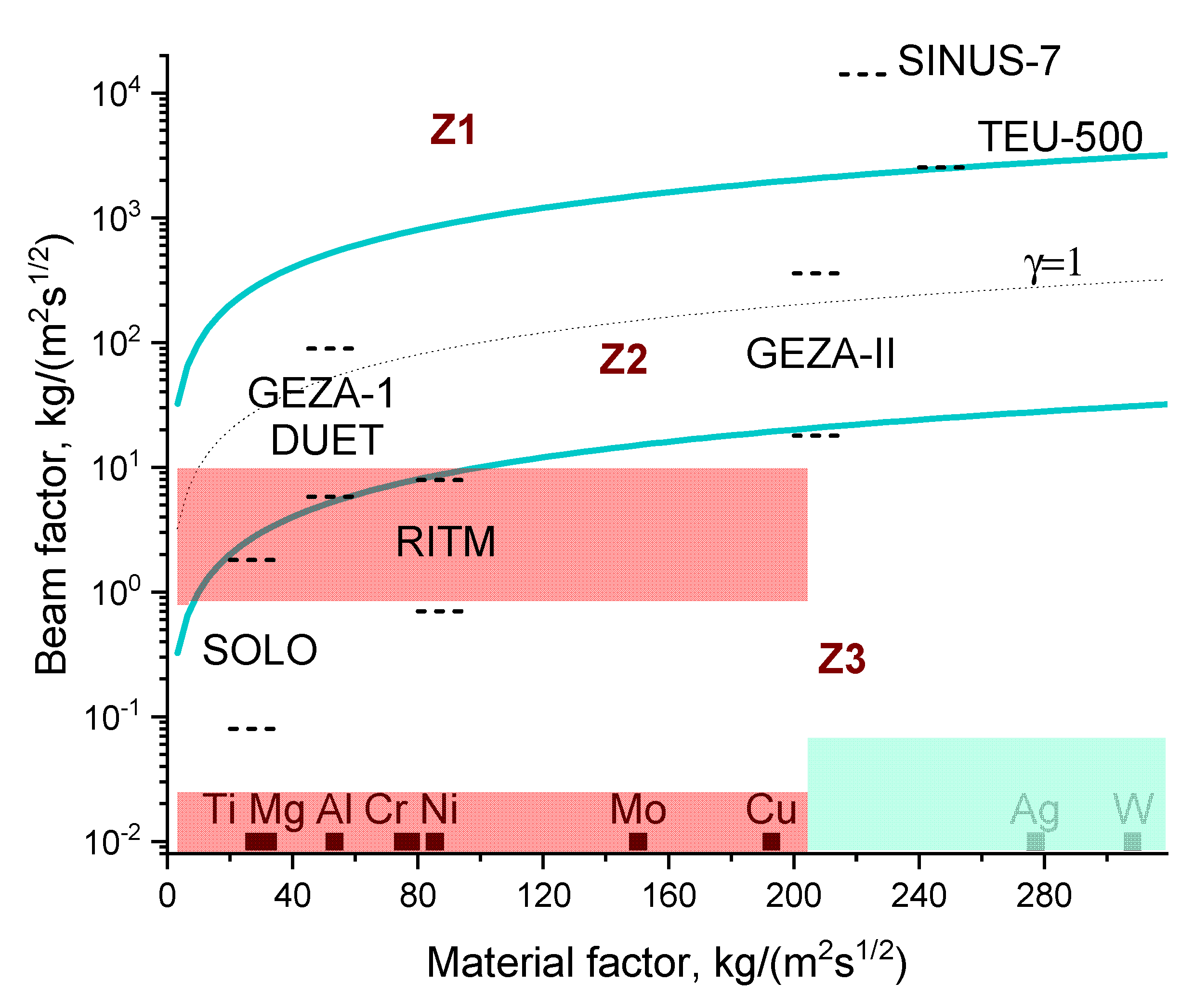
| Name | Accelerating voltage U, kV | Pulse duration τ, µs | Beam factor, kg/(m2s1/2) | Refs. |
|---|---|---|---|---|
| SOLO | 5–25 | 50–200 | 0.1–1.8 | 1-5 |
| RITM | 5–25 | 2.5 | 0.7–7.9 | 6-20 |
| GESA-I | 50–150 | 4–40 | 5.6–91.9 | 21-22 |
| DUET | 100–200 | 10–300 | 5.8–89.4 | 23-25 |
| GESA-II | 200–400 | 5–250 | 17.9–357.8 | 21-22 |
| TEU-500 | 400 | 0.1 | 2529 | 26-28 |
| SINUS-7 | 1000 | 0.05 | 14142 | 29-32 |
| Metal | Density ρ, kg/m3 | Heat capacity cp, J/(kg K) | Thermal conductivity λ, W/(m K) | Melting point Tm, K | Material factor, kg/(m2s1/2) |
|---|---|---|---|---|---|
| Mg | 1.70⋅103 | 1037 | 156 | 923 | 32.0 |
| Be | 1.85⋅103 | 1825 | 201 | 1551 | 28.5 |
| Al | 2.70⋅103 | 900 | 237 | 933 | 53.3 |
| Ti | 4.54⋅103 | 522 | 22 | 1943 | 27.6 |
| BaseM | 7.00⋅103 | 560 | 67 | 1000 | 57.9 |
| Cr | 7.20⋅103 | 448 | 94 | 2130 | 77.7 |
| Fe | 7.90⋅103 | 448 | 80 | 1812 | 75.1 |
| Ni | 8.90⋅103 | 445 | 91 | 1453 | 85.3 |
| Cu | 8.92⋅103 | 384 | 400 | 1357 | 192.8 |
| Zr | 6.51⋅103 | 277.7 | 22.7 | 2155 | 46.1 |
| Mo | 1.02⋅103 | 250 | 138 | 2893 | 150.2 |
| Ag | 1.05⋅103 | 235 | 429 | 1235 | 276.9 |
| W | 1.93⋅103 | 132 | 163 | 3695 | 308.2 |
Disclaimer/Publisher’s Note: The statements, opinions and data contained in all publications are solely those of the individual author(s) and contributor(s) and not of MDPI and/or the editor(s). MDPI and/or the editor(s) disclaim responsibility for any injury to people or property resulting from any ideas, methods, instructions or products referred to in the content. |
© 2023 by the authors. Licensee MDPI, Basel, Switzerland. This article is an open access article distributed under the terms and conditions of the Creative Commons Attribution (CC BY) license (http://creativecommons.org/licenses/by/4.0/).


