Preprint
Article

Paving the Way for a Multiplanetary Future for Humanity: How the Relativistic Motor May Enable Eventually Interplanetary Travel

Altmetrics

Downloads

108

Views

19

Comments

0

A peer-reviewed article of this preprint also exists.

This version is not peer-reviewed

Submitted:

13 July 2023

Posted:

14 July 2023

You are already at the latest version

Alerts
Abstract
Current spacecraft mass are mostly fuel, this is dictated by the lack of fueling stations in space and also by the Tsiolkovsky rocket equation which defines the mass ratio needed to escape earths gravity. The Tsiolkovsky rocket equation gives a relationship between the mass ratio and the final velocity in multiples of the exhaust speed, and dictates a high mass ration for current exhaust speeds. A relativistic motor exchanging momentum and energy with the electromagnetic field may mitigate such considerations, enabling efficient interplanetary travel. In this paper we will discuss the advantages and challenges of this novel mover for space transportation.
Keywords: 
Subject: Physical Sciences  -   Space Science

1. Introduction

Today’s space vehicles total mass are mostly fuel. The reason for this is simple there are no fueling stations in space. This problem will become even more severe as interplanetary travel is envisioned.
Motion means kinetic energy and momentum. While energy is abundant in interplanetary space as sunlight can be converted to other forms of energy, the real problem is momentum. Since momentum is conserved, how can one entail motion which means momentum creation? This problem is solved on earth by the car gaining momentum by pushing the road backward. Similarly a jet plane is propagating by pushing the air behind it. That is forward momenta is gained by the vehicle while at the same time generating momenta of the same magnitude but in opposite direction in the surrounding medium. The total momentum gained is of course null, which is the essence of linear momentum conservation.
But what can one push against in empty space? The common answer is against nothing. So how can we travel? Again the common wisdom is by the rocket mechanism that is carrying with us material and ejecting it as we go. The momentum gained by the vehicle is equal but opposite in sign to the momentum of the ejected material. This situation dictates that a huge part of a spacecraft devoted to an interplanetary mission must be just fuel.
The situation becomes even more dire when one needs to take into account that a space craft must escape a deep gravitational well. First the Earths gravitational well and then the gravitational well of the planet to which it travels (Mars?) when coming back.
The Tsiolkovsky rocket equation [1] defines the mass ratio needed to escape earths gravity. The Mass ratio is the ratio between the rocket’s initial mass and its final mass. The Tsiolkovsky rocket equation gives a relationship between the mass ratio and the final velocity in multiples of the exhaust speed, and dictates a high mass ratio for current exhaust speeds.
Δ v = v e ln m 0 m f
in the above Δ v is the maximum change of velocity of the vehicle (with no external forces acting), v e is the effective exhaust velocity, m 0 is the initial total mass that is including the propellant mass, and m f is the final total mass without propellant. The equation is depicted in Figure 1.
As typical exhaust velocities are [2]:
  • 1.7 to 2.9 km/s for liquid monopropellants.
  • 2.9 to 4.5 km/s for liquid bipropellants.
  • 2.1 to 3.2 km/s for solid propellants.
and the earth escape velocity is 11.2 km/s, it follows from Figure 1 that a large mass ratio is needed just to escape the earth’s gravity not to mention reaching an appreciable velocity that will allow a reasonable travel time to a nearby planet.
The above considerations seem unescapable. Indeed, without propellant how can one hope to defeat the requirement to conserve linear momentum and with it the required mass ratio? And yet one must not forget the linear momentum is not only a property of matter but also a property of the electromagnetic field [4,6,10]. Thus in principle a space vehicle might propagate using the energy supplied by the sun and contained within its storage devices while the momentum it gains is balanced by the same amount of momentum but of opposite direction which is transferred to the electromagnetic field.
A relativistic motor exchanging momentum and energy with the electromagnetic field may mitigate mass ratio considerations, enabling efficient interplanetary travel. In this paper we will discuss the advantages and challenges of this novel mover for space transportation.
A detailed introduction to the subject of relativistic motors in general and microscopic relativistic engines in particular with suitable references can be found in [15] and will not repeated here, the interested reader is referred to the original text. A brief history of the relativistic engine is given below.
The first relativistic engine suggested was base on electromagnetic field retardation of two time dependent loop currents [3] (see Figure 2).
Jefimenko’s [10,13] formula was used to calculate the total force F T operating on the center of mass of a system resulting in the formula:
F T μ 0 8 π ( h c ) 2 K 122 I 2 I 1 ( 2 ) ( t ) , I 1 ( n ) ( t ) n I 1 ( t ) t n
in which μ 0 is the magnetic permeability of the vacuum, c is the velocity of light in the vacuum, h is at typical length scale of the system and K 122 is a dimensionless vector which depend on the geometry of the loops. I 2 is a static current and I 1 ( t ) is a time dependent current. This was later generalized to calculate the total force in a system of permanent magnet and a current loop [5]. As force is applied for a finite duration, momentum will be acquired and kinetic energy for the entire system. It may superficially seem that the laws of momentum and energy conservation are violated, but this is not so. Linear momentum conservation was validated in [6]. It was shown that the momentum gained by the field P f i e l d 12 is the same as momentum gained by the engine P m e c h but in an opposite direction:
P f i e l d 12 = μ 0 8 π I 2 I 1 ( 1 ) ( t ) h 2 c 2 K 122 = P m e c h .
The exchange of energy between the kinetic part of the relativistic engine and the electromagnetic field was elaborated in [7,8,9]. It was demonstrated that the electromagnetic energy consumed is six times the kinetic energy provided to the engine. It was also shown that energy is radiated from the engine if the coils are misaligned.
Our preliminary analysis assumed bodies that were electric charge natural. In a later paper [14] charged bodies were analyzed. The charged engine allows to maintain a finite momentum even if the current is not continuously increasing, as is dictated by the current derivative term in equation (3) (which requires a monotonously increasing current for a uniform motion in some direction). This more general case result is a total force in the center of mass and total linear momentum given by the formulae:
F T = μ 0 4 π t d 3 x 1 d 3 x 2 1 2 ρ 2 t ρ 1 ρ 1 t ρ 2 R ^ ( ρ 1 J 2 + ρ 2 J 1 ) R 1 , R x 1 x 2
P m e c h ( t ) = μ 0 4 π d 3 x 1 d 3 x 2 1 2 ρ 2 t ρ 1 ρ 1 t ρ 2 R ^ ( ρ 1 J 2 + ρ 2 J 1 ) R 1
in the above ρ is the charge density and J is the current density of the two subsystems 1 and 2 respectively, and an integrations is required over the volumes of the two sub systems.
However, due to dielectric breakdown which dictated a maximal value to charge density and current density limitations that can be transferred even through a superconducting wire it is shown that for any reasonable geometrical size the momentum that can be gained in a relativistic charged engine is rather limited. Table 1 obtained in [14] demonstrates the severe limitations of macroscopic configurations:
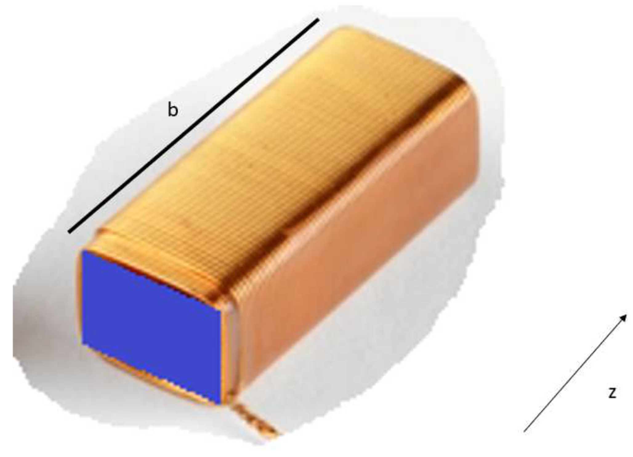
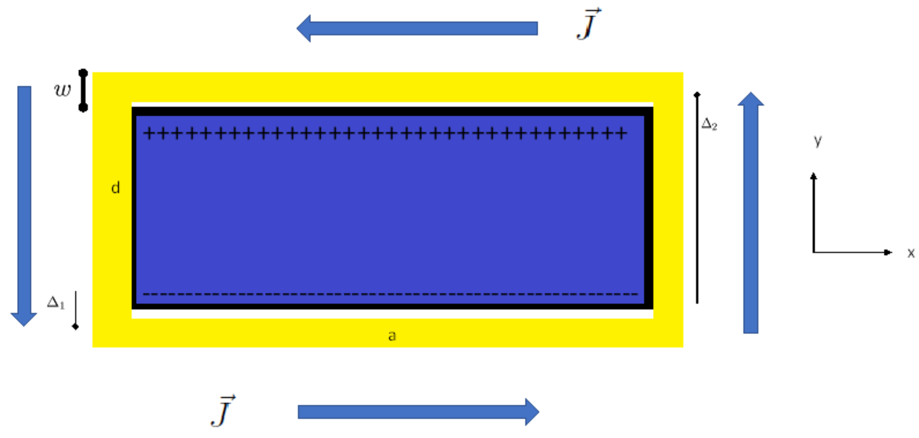
The physical structure of this particular relativistic engine and its geometric parameters are depicted in Figure 3 and Figure 4.
The above limitations suggested to use the high charge densities that are available in the microscopic realm, for example in ionic crystals. We have pursued this idea in a previous paper [15] in which we calculated the high charge densities and current densities in the atomic level. We also deduced a preliminary form for the optimized wave function in terms of relativistic engine performance in two cases a wave packet in a hydrogen atom and a eigen state in a simple molecule which introduces a static electric field of broken spherical symmetry.
To conclude the relativistic motor is well suited for space travel and interplanetary motion as it posses the following attributes:
  • Allows 3-axis motion (including vertical)
  • No moving parts
  • Zero fuel consumption
  • Zero carbon emission
  • Needs only electromagnetic energy (which may be provided by solar panels).
  • Ideal solution for space travel in which currently much of the space vehicle mass is devoted to fuel
  • Highly efficient, in principle kinetic energy can be converted back to electromagnetic energy.
However, to reach a practical relativistic engine that will serve humanity in interplanetary travel one must manipulate matter at subatomic levels, a feat that is quite challenging. In this paper we shall investigate two ways of doing so one that is related to free electrons and the other to confined electrons. While we start with a classical description of the problem we cannot and do not ignore the fact that on the atomic level a quantum description is required. It will be shown that the quantum effects are much more important for confined electrons than for free electrons. We shall not derive the basic equations of the relativistic engine here the interested reader is referred to [14,15], we shall also use the same notations as in the previous papers and will not redefine the symbols.
In the current paper we will show that both free electrons and confined electrons can be put in a configuration supporting a relativistic motor effect which will allow eventually the construction of interplanetary space-craft. However, quantum mechanics (for spin and spin less electrons) is only important in the confined electron case. We thus derive the form of the electromagnetic field needed to maintain the appropriate wave packet that support a relativistic engine effect in the confined case.

2. Relativistic engine in the microscopic scale

2.1. A classical electron

Before introducing quantum considerations we shall first consider a classical system of two point particles each with a charge of absolute value | e | . We shall assume one charge to be stationary while the other moving with velocity v 2 , it thus follows that system 2 has current density of [14]:
J 2 = ρ 2 v 2 = e δ 3 ( x 2 x ( t ) ) v 2
and system 1 has a charge density:
ρ 1 = ± e δ 3 ( x 1 ) ,
in which we assume for convenience that the stationary charge is located at the origin of the coordinates.

2.1.1. Proximity considerations

Plugging equation (6) and equation (7) into Equation (3) of [15]:
P ( t ) = μ 0 4 π d 3 x 1 d 3 x 2 ρ 1 J 2 R 1 = = μ 0 e 2 4 π v 2 | x ( t ) |
Taking the total mass of the two particle system to be m t = m 1 + m 2 we arrive at a center of mass velocity:
v c m ( t ) = P ( t ) m t = μ 0 e 2 4 π m t v 2 | x ( t ) | .
The above equation makes explicit the fundamental conflicting requirements of the concept. To have significant speed in the center of mass the particles must be close to each other thus we would like to have a confined system. On the other hand we would like to have a high v 2 with a constant direction, this is impossible in a confined system as in such a case, v 2 must eventually change direction. Thus for the center of mass to obtain a speed v c m ( t ) at time t the particles must be at the proximity:
| x ( t ) | = μ 0 e 2 4 π m t v 2 v c m ( t ) .
If the particles are an electron and a proton m t m p
| x ( t ) | = μ 0 e 2 4 π m p v 2 v c m ( t ) .
It is not difficult to bring an electron to move very close to the speed of light such that: v 2 c , for example for a 99% of the speed of light with a low energy accelerator:
v 2 = 0.99 c E k = m e c 2 1 ( v 2 c ) 2 3.6 MeV .
thus we shall take v 2 = c and obtain:
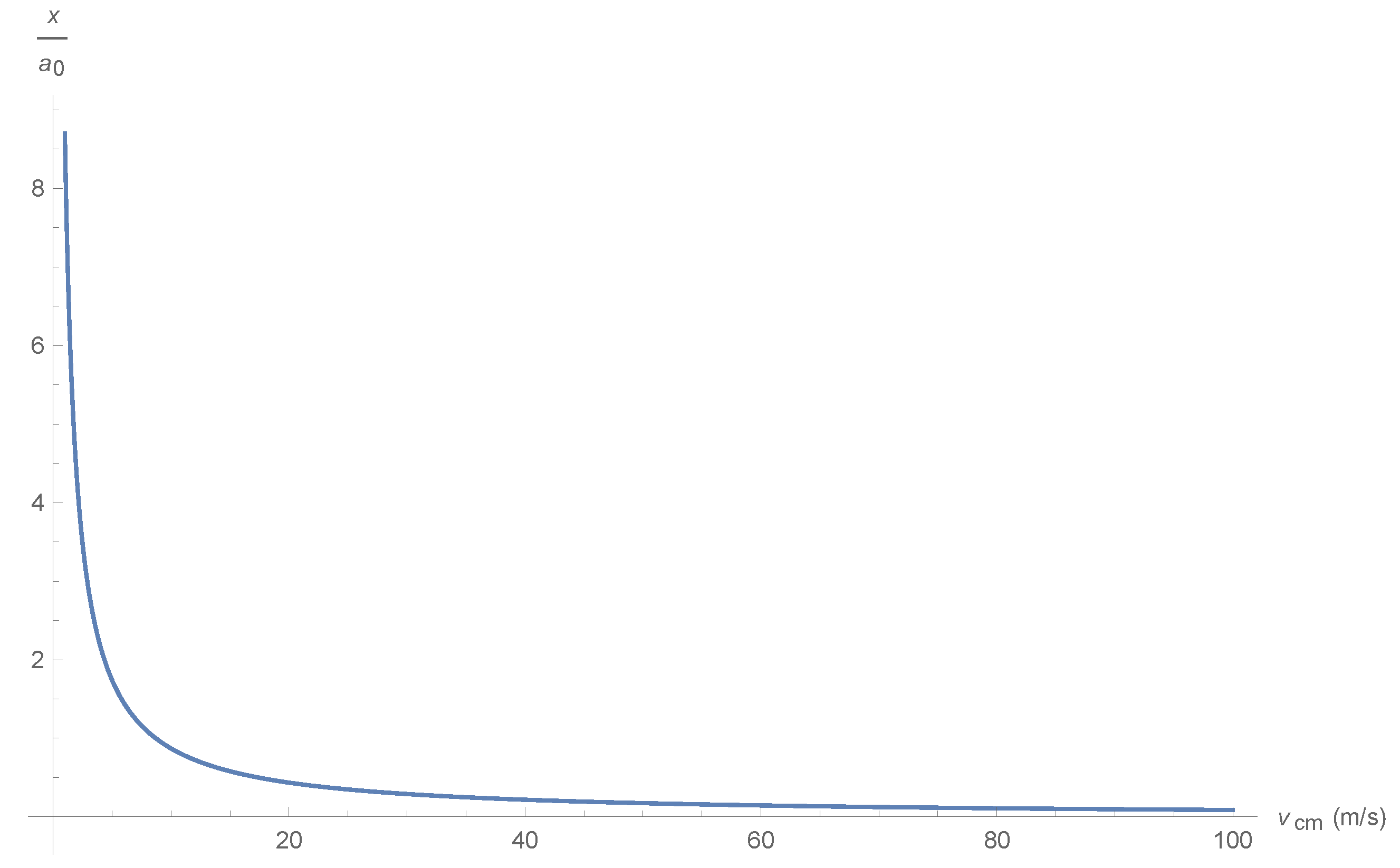
| x ( t ) | = μ 0 e 2 c 4 π m p 1 v c m ( t ) = 4.6 · 10 10 v c m ( t ) = 8.7 a 0 v c m ( t ) .
in which the last expression contains the Bohr radius:
a 0 4 π ϵ 0 2 m e e 2 2 k m e e 2 0.53 10 10 m , m e m e m p m e + m p m e .
The relation between the require distance and the desired velocity for the two particle system is described in Figure 5.
Thus a typical car’s velocity: v c m = 50 m/s = 180 km/h is obtained for:
| x ( t ) | 0.174 a 0 .
If we require the hydrogen relativistic engine to reach the earth’s escape velocity of v c m = 11.2 km/s then we must have a proximity of:
| x ( t ) | 48.8 r p
in which r p = 8.4 10 16 m is the proton charge radius. Thus the distance between electron and proton must be of a nuclear size rather than an atomic size. Finally if we imagine that the relativistic engine will reach relativistic velocities v c m 0.1 c it follows that:
| x ( t ) | 0.018 r p
that is the electron proton system is of sub nuclear dimensions.
An engine suitable for interplanetary travel must include a macroscopic amount of such atoms and it must carry not just itself but also some payload.

2.1.2. An unconfined electron

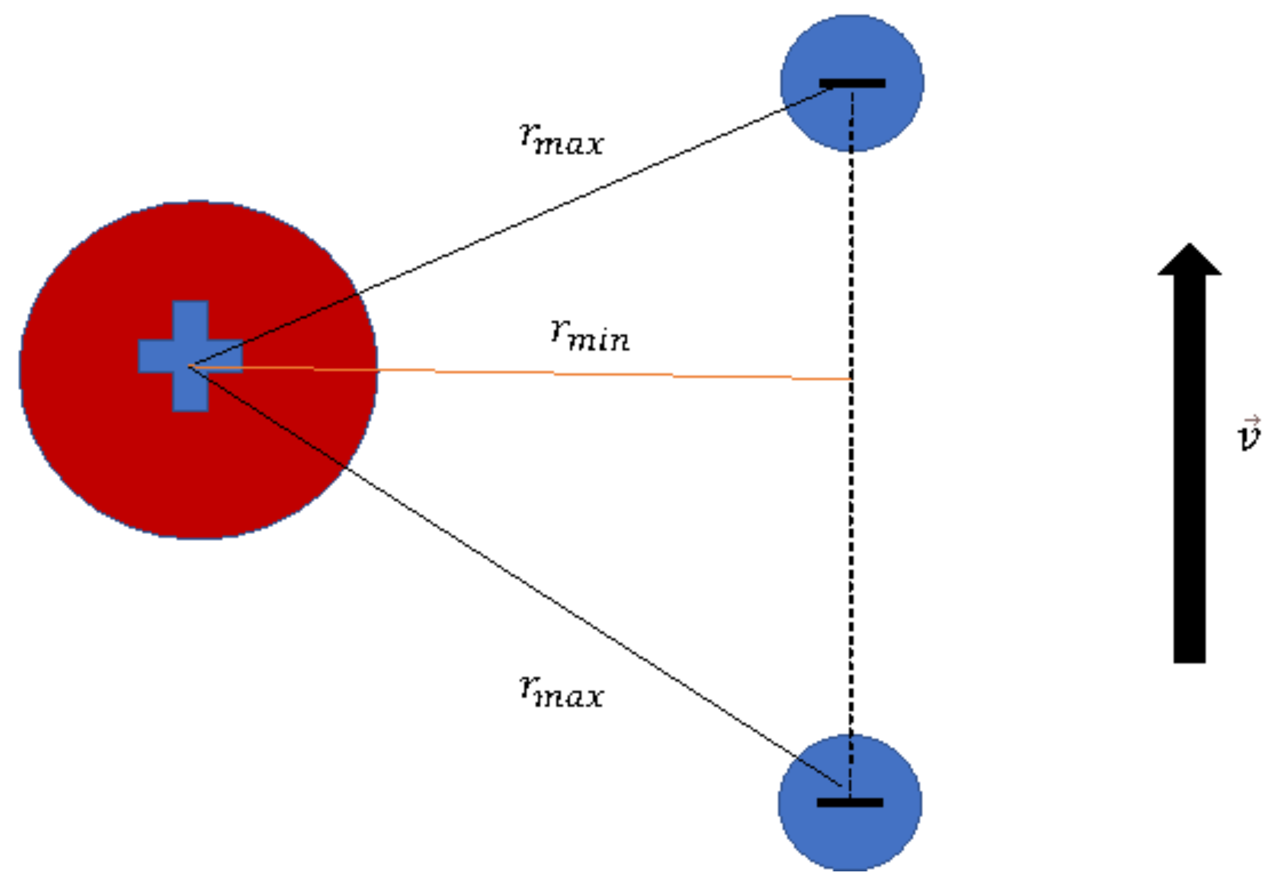
It seems that a way to circumvent this inherent contradiction between proximity and velocity is to use a train of particles in which for each particle leaving the desired range a new one enters as depicted in Figure 6.
Let us assume that we keep at least one electron from the proton at a distance which is not smaller than a distance r m a x and bigger that a distance r m i n , it follow that the duration between successive electrons is:
Δ t = 2 r m a x 2 r m i n 2 c
If we take r m i n to be the distance for a v c m = 50 m/s, that is r m i n = 0.174 a 0 and r m a x = 3 r m i n it follows that:
Δ t 1.7 · 10 19 s I = e Δ t 0.92 A
hence the needed current is not too excessive. The practical problem is how to put high velocity electrons in the vicinity of protons. One may imagine, a high density plasma (see Figure 7).
Made of protons and electrons in which the average density between protons is 2 r m i n the density of such a plasma is:
Δ V = ( 2 r m i n ) 3 6.2 · 10 33 m 3 ρ p l a s m a = m p Δ V 2.7 · 10 5 Kg / m 3
this is much higher than the density of solid hydrogen r h o S H 86 Kg / m 3 in which the typical distance between atoms is about 5 Bohr radii. We notice that a 3.7 Liter of the above plasma will weigh about one metric ton, and could easily move a standard car. We also notice that, solid hydrogen can only be obtained under unusual conditions of low temperature and high pressure. Another alternative is to have sparse protons but high density electrons with typical distance of 2 r m i n . However, this will lead to for the Δ V of equation (20) to a charge density of:
ρ c h a r g e = e Δ V 2.6 · 10 13 C / m 3
Obviously, such a configuration cannot hold. If we take for simplicity the configuration to be spherical of radius r s , then according to Equation (9) of [15] the electric field on its surface would be:
E r = k Q r s 2 = k 4 π 3 ρ c h a r g e r s 3 r s 2 = k 4 π 3 ρ c h a r g e r s 9.7 · 10 23 r s
Thus an electron on the surface of the said sphere will be accelerated outwards with an acceleration of:
r ¨ = e E r m e 1.7 · 10 35 r s m / s 2 .
The typical disintegration time of the above configuration is:
τ d i s i n t e g r a t i o n = r s r ¨ 2.4 · 10 18 s .
regardless of the size of the sphere. We shall make a point regarding the typical charge separation that is empirically available. According to Section 7 the maximal charge density for air is σ m a x 53 μ C / m 2 . In terms of electron number density this is:
σ m a x e l e c t r o n s = σ m a x | e | 3.3 · 10 14 m 2
which translates into a typical spatial separation of:
δ e = 1 σ m a x e l e c t r o n s 5.5 · 10 8 m
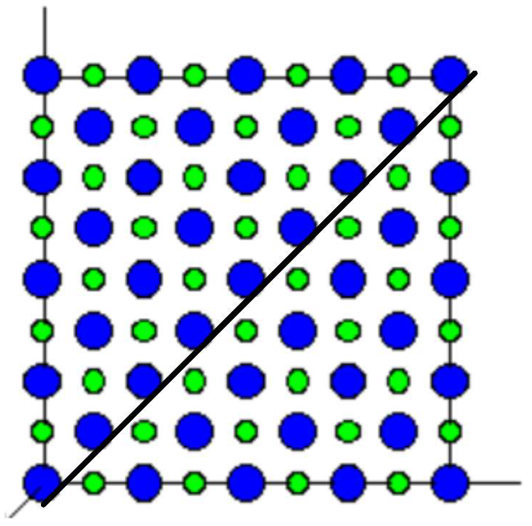
this separation is much too large to obtain a significant relativistic motor effect. On the other hand, looking back at the ionic crystal of Figure 1 of [15] it is easy to draw a trajectory for the said stream of electrons as depicted in Figure 8:
As the electron passes through more positive ions it becomes closer to the positive ion, if fact even an electron at a distance of a lattice constant of l 564 pm will feel a force perpendicular to its trajectory and towards the positive ions line of about:
F k e 2 l 4 · 10 19 Newton .
Thus it will have a perpendicular acceleration towards the positive ionic line of about:
r ¨ = F m e 4.5 · 10 11 m / s 2 ,
for a duration of about Δ t (see equation (19)), in each ion passage. Thus the velocity towards the positive ion line would be at least:
v Δ t r ¨ 7.8 · 10 8 m / s ,
but of course the acceleration and velocity will become larger as the electron reaches closer to the ion line. Thus the electron will reach the ion line in a time shorter than:
τ i o n l i n e v l 0.007 s ,
This time can be shortened by applying an external electric field perpendicular to the ion line and away from the line. Moreover, a slower electron beam will have a more time to converge to the ion line which poses an interesting optimization problem, balancing between the desired proximity to the ion line and the electron beam speed. We notice that a 99 % speed of light will hardly converge to the ion line even if the engine is one meter thick, because it will pass it in about three nano seconds. If convergence to the ion line is indeed achieved we expect an oscillatory motion around the positive ion line in which inverse beta decay will occasionally occur. Of course the most significant relativistic motor effects will occur in the times in which the electron is closer to the positive ion line.

2.1.3. A confined electron

A confined classical electron can be put in an elliptical trajectory that can be occasionally favourable to the relativistic motor effect, see Figure 9.
One can see that the positive relativistic motor effect near the proton at a distance r m i n , is much greater than the negative relativistic motor effect which occurs due to the motion in the opposite direction but at a much larger separation r m a x . We also notice that the orthogonal motions will cancel each other as they occur in opposite directions. Unfortunately such a description is not very useful as quantum effects play a major rule for confined electron, thus we conclude our discussion regarding classical electrons and move to the discussion of quantum electrons.

3. Schrödinger’s electron

Quantum mechanics according to the Copenhagen interpretation has lost faith in our ability to predict precisely the whereabouts of even a single particle. What the theory does predict precisely is the evolution in time of a quantity denoted "the quantum wave function", which is related to a quantum particle whereabouts in a statistical manner. This evolution is described by an equation suggested by Schrödinger [22]:
i ψ ˙ = H ^ S ψ , H ^ S = 1 2 m e i e A 2 e Φ
in the above i = 1 and ψ is the complex wave function. ψ ˙ = ψ t is the partial time derivative of the wave function. = h 2 π is Planck’s constant divided by 2 π . However, this presentation of quantum mechanics is rather abstract and does not give any physical picture regarding the meaning of the quantities involved. Thus we write the quantum wave function using its modulus a and phase ϕ :
ψ = a e i ϕ .
The probability density and flux are defined as:
ρ ˜ = ψ * ψ , J S = 2 m e i [ ψ * ψ ( ψ * ) ψ ] e m e A ρ ˜ = ρ ˜ ( m e ϕ e m e A ) .
We thus define the velocity field using the natural definition:
v S = J S ρ ˜ = m e ϕ e m e A
and the mass density is defined as:
ρ ^ = m e ρ ˜ = m e a 2 .
It is easy to show from equation (31) that the continuity equation is satisfied:
ρ ^ t + · ( ρ ^ v S ) = 0
Hence v S field is the velocity associated with mass conservation. However, it is also the mass associate with probability a 2 (by Born’s interpretational postulate) and charge density ρ = e a 2 . The equation for the phase ϕ derived from equation (31) is as follows:
ϕ t + 1 2 m e ϕ e A 2 e Φ = 2 2 a 2 m e a = Q
In term of the velocity defined in equation (34) one obtains the following equation of motion (see Madelung [23] and Holland [24]):
d v S d t = v S t + ( v S · ) v S = Q m e + e m e ( E + v × B )
The right hand side of the above equation contains the "quantum correction":
Q = 2 2 m e 2 ρ ^ ρ ^ .
For the meaning of this correction in terms of information theory see: [25,26,27]. These results illustrates the advantages of using the two variables, phase and modulus, to obtain equations of motion that have a substantially different form than the familiar Schrödinger equation (although having the same mathematical content) and have straightforward physical interpretations [29].
The quantum correction Q will of course disappear in the classical limit 0 , but even if one intends to consider the quantum equation in its full rigor, one needs to take into account the expansion of an unconfined wave function. As Q is related to the typical gradient of the wave function amplitude it follows that as the function becomes smeared over time and the gradient becomes small the quantum correction becomes negligible. To put in quantitative terms:
F Q = Q 2 2 m e L R 3 , L R R | R |
in which L R is the typical length of the amplitudes gradient. Thus:
| F Q | < < | F L | L R > > L R c = 2 2 m e F L 1 3 .
in which F L = e ( E + v × B ) is the classical Lorentz force [30]. For the current application in which a free electron transverses a macroscopic length this term will certainly be negligible. However, for a confined electron this term cannot be neglected as we show in a following section describing the hydrogen atom.

4. Pauli’s electron

Schrödinger’s quantum mechanics is limited to the description of spin less particles. Indeed the need for spin became necessary as Schrödinger equation could not account for the result of the Stern Gerlach experiments, predicting a single spot instead of the two spots obtained for hydrogen atoms. Thus Pauli introduced his equation for a non-relativistic particle with spin is given by:
i ψ ˙ = H ^ P ψ , H ^ P = 2 2 m e [ i e A ] 2 + μ B · σ + e Φ = H ^ S I + μ B · σ
ψ here is a two dimensional complex column vector (also denoted as spinor), H ^ P is a two dimensional hermitian operator matrix, μ is the magnetic moment of the particle, and I is a two dimensional unit matrix. σ is a vector of two dimensional Pauli matrices which can be represented as follows:
σ 1 = 0 1 1 0 , σ 2 = 0 i i 0 , σ 3 = 1 0 0 1 .
The ad-hoc nature of this equation was later amended as it became clear that this is the non relativistic limit of the relativistic Dirac equation. A spinor ψ satisfying equation (42) must also satisfy a continuity equation of the form:
ρ p t + · j = 0 .
In the above:
ρ p = ψ ψ , j = 2 m e i [ ψ ψ ( ψ ) ψ ] e m e A ρ p .
The symbol ψ represents a row spinor (the transpose) whose components are equal to the complex conjugate of the column spinor ψ . Comparing the standard continuity equation to equation (44) suggests the definition of a velocity field as follows [24]:
v = j ρ p = 2 m e i ρ p [ ψ ψ ( ψ ) ψ ] e m e A .
Holland [24] has suggested the following representation of the spinor:
ψ = R e i χ 2 cos θ 2 e i ϕ 2 i sin θ 2 e i ϕ 2 ψ ψ .
In terms of this representation the density is given as:
R 2 = ψ ψ = ρ p R = ρ p .
The mass density is given as:
ρ ^ = m e ψ ψ = m e R 2 = m e ρ p .
The probability amplitudes for spin up and spin down electrons are given by:
a = ψ = R cos θ 2 , a = ψ = R sin θ 2
Let us now look at the expectation value of the spin:
< 2 σ > = 2 ψ σ ψ d 3 x = 2 ψ σ ψ ρ p ρ p d 3 x
The spin density can be calculated using the representation given in equation (47) as:
s ^ ψ σ ψ ρ p = ( sin θ sin ϕ , sin θ cos ϕ , cos θ ) , | s ^ | = s ^ · s ^ = 1 .
This gives an easy physical interpretation to the variables θ , ϕ as angles which describe the projection of the spin density on the axes. θ is the elevation angle of the spin density vector and ϕ is the azimuthal angle of the same. The velocity field can now be calculated by inserting ψ given in equation (47) into equation (46):
v = 2 m e ( χ + cos θ ϕ ) e m e A .
We are now in a position to calculate the material derivative of the velocity and obtain the equation of motion for a particle with ([24] p. 393 equation (9.3.19)):
d v d t = ( Q m e ) 2 m e 2 1 ρ p k ( ρ p s ^ j k s ^ j ) + e m e ( E + v × B ) μ m e ( B j ) s ^ j .
The Pauli equation of motion differs from the classical equation motion and the Schrödinger’s equation of motion. In addition to the Schrödinger quantum force correction we have an additional spin quantum force correction:
F Q S 2 4 m e 1 ρ p k ( ρ p s ^ j k s ^ j ) = 2 4 m e k ( s ^ j k s ^ j ) + k ρ p ρ p s ^ j k s ^ j
as well as a term characterizing the interaction of the spin with a gradient of the magnetic field, which is the Stern-Gerlach term.
F g r a d B S μ ( B j ) s j
As both the upper and lower spin components of the wave function are expanding in free space the gradients which appear in F Q S will tend to diminish for any macroscopic scale making this force negligible. To estimate the condition quantitatively we introduce the typical spin length:
L s = min i { 1 , 2 , 3 } | s ^ i | 1
Using the above definition we may estimate the spin quantum force:
F Q S 2 4 m [ 1 L s 3 + 1 L s 2 L R ] = 2 4 m L s 2 [ 1 L s + 1 L R ]
this suggested the definition of the hybrid typical length:
L s R = [ 1 L s + 1 L R ] 1 = L s L s L R L R L R L s .
In terms of this typical length we may write:
F Q S 2 4 m e L s 2 L s R
Thus the conditions for a classical trajectory become:
F Q S F L L s 2 L s R 2 4 m e F L L s 2 4 m e F L 1 3 L s L R 2 4 m e F L L R 1 2 L R L s .
Another important equation derived from equation (42) is the equation of motion for the spin orientation vector ([24] p. 392 equation (9.3.16)):
d s ^ d t = 2 μ B e f f × s ^ , B e f f = B 2 4 μ m e R 2 i ( ρ i s ^ )
The quantum correction to the magnetic field explains [24] why a spin picks up the orientation of the field in a Stern-Gerlach experiment instead of precessing around it as a classical magnetic dipole would.
In the free electron scenario the only quantum term that might have a significance is the Stern-Gerlach term given in equation (56), however, it is well known that this term is negligible with respect to the Lorentz classical term, which is why Stern-Gerlach experiments are performed using natural particles. Thus as far as free electrons based relativistic engines are concerned, a classical analysis will suffice, this is not the case for a confined electron as we discuss in the next section.

5. The Hydrogen atom

The Hydrogen atom is one of the simplest quantum mechanical systems and was discussed in [15], we use the same notation as in [15] and will not redefine the notation here.
The associated velocity field of an eigen function is determined from its phase (Equation (44) in [15]) is:
v S = m e ϕ e m e A = m m e r sin θ φ ^ , A = 0 ,
which is azimuthal, thus for every eigenstate the electron is circulating some axis (the z axis which is arbitrarily defined). The speed of the electron in the hydrogen atom is thus:
v S = m m e r | sin θ | .
The speed will vanish for every eigenstate with a magnetic quantum number m = 0 including for the ground state. However, for every other magnetic quantum number the velocity field is singular both in the proton at r = 0 and on the north and south poles θ = 0 , π . Regrading the singularity at r = 0 this is not problem from a physical point of view as one can expect a different potential from the Coulomb potential inside the proton which is not a point particle. However, with regard to the south and north poles infinite velocities, this indicates a difficulty in the Hydrogen atom classical description in which relativistic considerations which enforce speeds smaller than the velocity of light c will be part of the solution. The static electron implies according to equation (38) that the force is zero. This is indeed the case, one can calculate the quantum potential for every state by using equation (39), however, for Hydrogen eigenstates it will be easier to use equation (37) and substitute the phase from Equation (44) of [15], this gives the expression:
Q n m = E n m 2 2 2 m e r 2 sin 2 θ + e Φ = E n m 2 2 2 m e r 2 sin 2 θ + k e 2 r
this can be verified by direct substitution of eigenstates in equation (39). It is easy to see that for m = 0 the total force vanishes:
( Q n m e Φ ) = E n = 0
We are now in a position to calculate the current density given in equation (33)
J = m e ρ ϕ = m e m e | ψ n l m | 2 φ ^ r sin θ
We notice that the current density is linear in the magnetic number m, in particular if m = 0 there is no current density and thus no relativistic motor effect. We conclude that for an isolated hydrogen in the ground state n = 1 , l = 0 , m = 0 there is no relativistic motor effect. But also in excited states in which the current density does not necessarily vanish there will be no relativistic motor effect if the potential acting on the electron is spherically or cylindrically symmetric as is evident from Equation (3) of [15].
How can we use an hydrogen atom as a component in a relativistic motor despite the fact that it is useless either in the ground state or in an excited state? In the following section we will suggest an approach in which the electron is not in an energy eigen state but in a superposition of states.
To understand the order of magnitude of the relativistic motor effect using a hydrogen atom one is referred to [15].

6. A simple wave packet

Let us assume an idealized wave packet of the form:
ψ = A e i k x , A = ρ ˜ c r < R m a x 0 r R m a x
in the above k and ρ ˜ c are constants. As the wave function must be normalized it follows that ρ ˜ c must take the following value:
ρ ˜ c = 3 4 π R m a x 3
hence this wave function has a linear phase and a uniform amplitude which is confined inside a sphere of radius R m a x . It is certainly not an eigen state of the Hydrogen atom Hamiltonian, the preparation of such a state will require a suitable electromagnetic field which will be discussed below. We have analyzed the properties of this wave function in [15] and will not repeat the analysis here.
The purpose of the wave function engineering is to achieve a wave function that will produce a stable linear momentum over macroscopic durations. This implies according to Equation (3) of [15] and equation (33) that we need to achieve a constant wave packet amplitude and constant phase gradient affected by a constant vector potential. A constant phase gradient does not imply a constant phase, in fact we may write the phase in the form:
ϕ = ϕ s ( x ) ϕ t ( t )
for a time independent amplitude it follows from equation (32):
ψ t = i ψ ϕ t t
Defining:
E ( t ) = ϕ t t
which is a time dependent function with units of energy, Schrödinger equation (31) implies that:
H ^ S ψ = E ( t ) ψ
Thus to achieve such a condition ψ must be an eigen function of some Hamiltonian H ^ S with a possibly time dependent eigenvalue E ( t ) . A Hamiltonian can be constructed by introducing suitable electromagnetic fields into the physical system. For example let us consider the somewhat artificial wave packet described in equation (68) which we now augment with a time dependent phase:
ψ = A m e i ( k x ϕ t ( t ) ) , A m = ρ ˜ c r < R m a x 0 r R m a x
We shall now plug the above expression into equation (31) and ignore the nonphysical derivatives connected to the fact that the above oversimplified wave packet is not smooth at r = R m a x , it follows that:
E ( t ) = 2 k 2 2 m e e Φ e k m e A x + e 2 A 2 2 m e ,
in the above we took advantage of the gauge freedom and assumed a Coulomb gauge · A = 0 which is of course not physically restrictive. This allows two types of solutions. In one case we assume A x = 0 , that is we assume that there is no vector potential component in the direction of motion of the wave packet. Denoting the perpendicular vector potential as A = A y y ^ + A z z ^ it follows that:
A = ± 2 m e e E ( t ) + e Φ 2 k 2 2 m e .
If, however, A x 0 it follows that:
A x = 1 e k ± 2 m e E ( t ) e 2 A 2 + 2 m e e Φ .

7. Discussion

The main results of this paper are the possibility of implementing a relativistic motor in the atomic and nano scales. It is shown that two approaches are possible. In one case we consider free propagating electrons which moves nevertheless in proximity to the nucleus but have enough energy not to be captured by the nucleus, we also consider the case of confined electrons.
Free electrons are classical and quantum forces are shown to be negligible due to the phenomena of wave packet spreading, thus a relativistic engine based on free electrons is analyzed classically.
For confined electrons quantum effects are important. Unfortunately it is shown that a Hydrogen atom whether in a ground or excited state does not produce any momentum according to the relativistic motor equation. We study the case in which an electron is put in a wave packet state which is an eigen state of an unspecified Hamiltonian. The Electromagnetic field to generate such a Hamiltonian are calculated.

8. Conclusion

The requirement to construct an engine suitable for interplanetary travel which is based on the rocket effect, entails an enormous supply of fuel to be carried with the vehicle. Basically most of the spacecraft should be fuel. An alternative is thus suggested based on the relativistic motor effect, in which no fuel is needed.
Despite the theoretical possibility to construct a working relativistic motor suitable for space craft which are intended for interplanetary travel, in practice this will not be a trivial task and will involve the generation of a highly localized wave packet or alternatively a very narrow electron beam. Thus in a study which is not a merely preliminary as this one, a more realistic wave packet should be considered and the sources of the electromagnetic field needed to achieve this goal need to be specified.
Additional directions for future studies which are arise from this paper include:
  • The analysis of a relativistic motor of which its components move also at relativistic speeds and not just the electromagnetic signals transmitted between the components. The need for this arises as the electron studied in the current paper may move at relativistic speeds.
  • For the same reason an analysis of the relativistic motor in the frame work of a Dirac theory is required. The Schrödinger equation and even the Pauli equation are not appropriate for the study of an electron at relativistic speeds.

References

  1. K. Tsiolkovsky, Investigation of World Spaces with Reactive Instruments, 1903 (Archived 2011-08-15 at the Wayback Machine in a RARed PDF). Available online: http://epizodsspace.airbase.ru/bibl/dorev-knigi/ciolkovskiy/sm.rar.
  2. Sutton, George P. (1992). Rocket Propulsion Elements: An Introduction to the Engineering of Rockets (6th ed.). Wiley-Interscience.
  3. Miron Tuval & Asher Yahalom "Newton’s Third Law in the Framework of Special Relativity" Eur. Phys. J. Plus 2014, 129, 240. [CrossRef]
  4. R. P. Feynman, R. B. Leighton & M. L. Sands, Feynman Lectures on Physics, Basic Books; revised 50th anniversary edition (2011).
  5. Asher Yahalom "Retardation in Special Relativity and the Design of a Relativistic Motor". Acta Physica Polonica A 2017, 131, 1285-1288. [CrossRef]
  6. Miron Tuval and Asher Yahalom "Momentum Conservation in a Relativistic Engine" Eur. Phys. J. Plus 2016, 131, 374. [CrossRef]
  7. Asher Yahalom "Preliminary Energy Considerations in a Relativistic Engine" Proceedings of the Israeli-Russian Bi-National Workshop "The optimization of composition, structure and properties of metals, oxides, composites, nano - and amorphous materials", page 203-213, 28 - 31 August 2017, Ariel, Israel.
  8. S. Rajput and A. Yahalom, "Material Engineering and Design of a Relativistic Engine: How to Avoid Radiation Losses". Advanced Engineering Forum ISSN: 2234-991X, Vol. 36, pp 126-131. Submitted: 2019-06-16, Accepted: 2020-05-18, Online: 2020-06-17. ©2020 Trans Tech Publications Ltd, Switzerland.
  9. Shailendra Rajput, Asher Yahalom & Hong Qin "Lorentz Symmetry Group, Retardation and Energy Transformations in a Relativistic Engine" Symmetry 2021, 13, 420. [CrossRef]
  10. J. D. Jackson, Classical Electrodynamics, Third Edition. Wiley: New York, (1999).
  11. M. Mansuripur, "Trouble with the Lorentz Law of Force: Incompatibility with Special Relativity and Momentum Conservation" PRL 2012, 108, 193901. [CrossRef]
  12. D. J. Griffiths & M. A. Heald, "Time dependent generalizations of the Biot-Savart and Coulomb laws" American Journal of Physics 1991, 59, 111-117. [CrossRef]
  13. Jefimenko, O.D. Electricity and Magnetism, Appleton-Century Crofts, New York (1966); 2nd edition, Electret Scientific, Star City, WV (1989).
  14. Rajput, Shailendra, and Asher Yahalom. "Newton’s Third Law in the Framework of Special Relativity for Charged Bodies" Symmetry 2021, 13, 1250. [CrossRef]
  15. Yahalom, Asher. "Newton’s Third Law in the Framework of Special Relativity for Charged Bodies Part 2: Preliminary Analysis of a Nano Relativistic Motor" Symmetry 2022, 14, 94. [CrossRef]
  16. Dielectric Strength of Air - the Physics Fact book. Available online: https://hypertextbook.com/facts/2000/AliceHong.shtml.
  17. Stefan Giere, Michael Kurrat & Ulf Schümann, HV Dielectric Strength of Shielding Electrodes in Vacuum Circuit-Breakers, 20th International Symposium on Discharges and Electrical Insulation in Vacuum - Tours, France - June 30 - July 5, 2002.
  18. Markus Gabrysch "Electronic properties of diamond".el.angstrom.uu.se. Retrieved 2013-08-10.
  19. L. Hsi-wen, T. Yu-Chong, Parylene-based electret power generators, J. Micromech. Microeng. 2008, 18, 104006.
  20. Jung, S.-G. et al. Enhanced critical current density in the pressure-induced magnetic state of the high-temperature superconductor FeSe. Sci. Rep. 2015, 5, 16385. [CrossRef]
  21. Peebles, P.Z. Probability, Random Variables and Random Signal Principles, McGraw Hill, New York, NY, USA (2001).
  22. E. Schrödinger, Ann. d. Phys. 81 109 (1926). English translation appears in E. Schrödinger, Collected Papers in Wave Mechanics (Blackie and Sons, London, 1928) p. 102.
  23. E. Madelung. Z. Phys. 1926, 40, 322.
  24. P.R. Holland The Quantum Theory of Motion (Cambridge University Press, Cambridge, 1993).
  25. A. Yahalom "The Fluid Dynamics of Spin". Molecular Physics 2018. [CrossRef]
  26. A. Yahalom "The Fluid Dynamics of Spin - a Fisher Information Perspective" arXiv:1802.09331v2 [cond-mat.] 6 Jul 2018. Proceedings of the Seventeenth Israeli - Russian Bi-National Workshop 2018 "The optimization of composition, structure and properties of metals, oxides, composites, nano and amorphous materials".
  27. Asher Yahalom "The Fluid Dynamics of Spin - a Fisher Information Perspective and Comoving Scalars" Chaotic Modeling and Simulation (CMSIM) 2020, 1, 17-30.
  28. Yahalom, A. Fisher Information Perspective of Pauli’s Electron. Entropy 2022, 24, 1721. [CrossRef]
  29. D. Bohm, Quantum Theory (Prentice Hall, New York, 1966) Section 12.6.
  30. Yahalom, A. Pauli’s Electron in Ehrenfest and Bohm Theories, a Comparative Study. Entropy 2023, 25, 190. [CrossRef]
  31. Humphreys, C.J. "The Sixth Series in the Spectrum of Atomic Hydrogen", Journal of Research of the National Bureau of Standards 1953, 50, 1. [CrossRef]
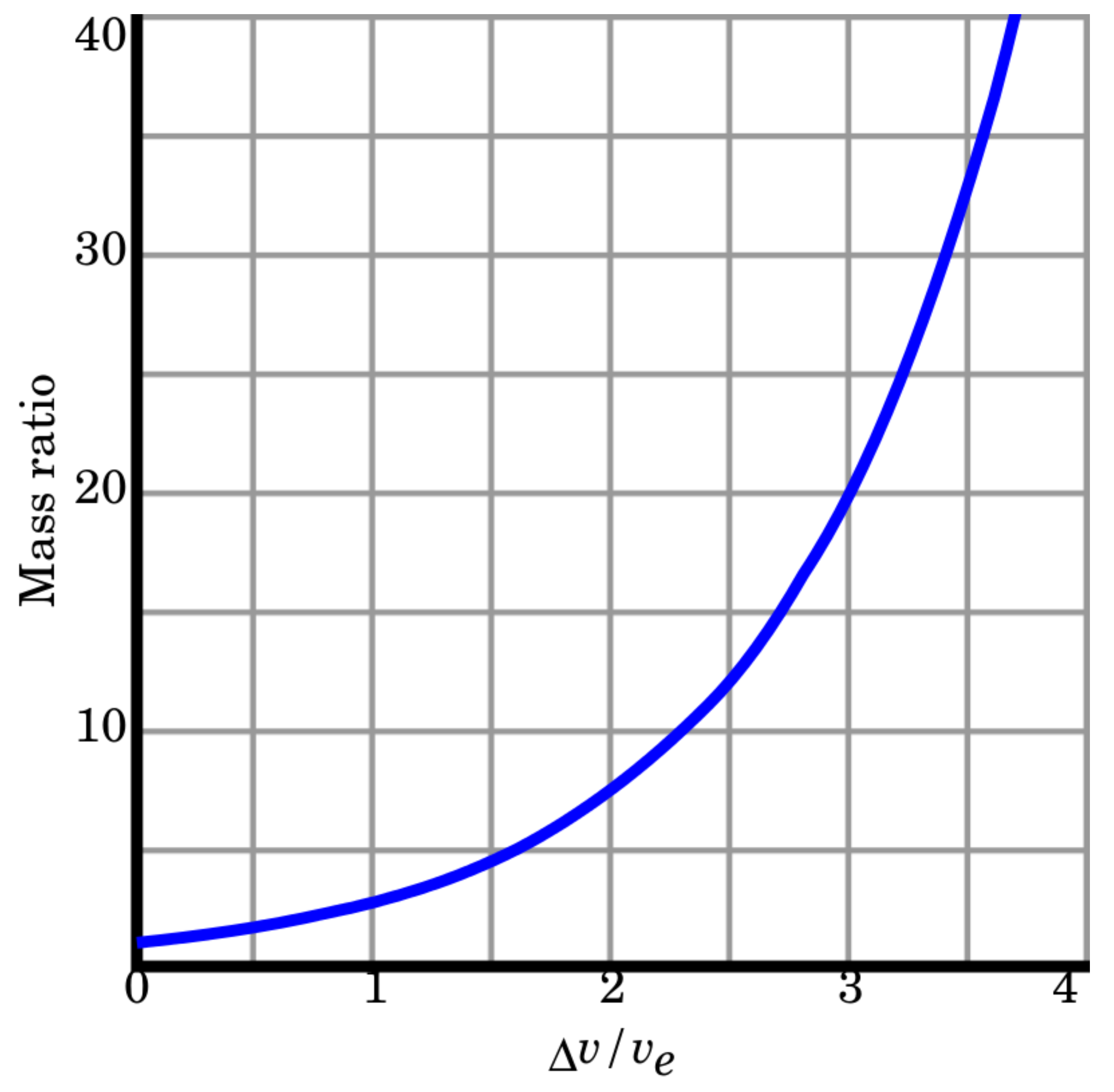
Figure 1. A rocket’s required mass ratio as a function of effective exhaust velocity ratio.
Preprints 79451 g001
Figure 2. Two current loops.
Preprints 79451 g002
Figure 3. A relativistic engine.
Preprints 79451 g003
Figure 4. A cross section of the relativistic engine.
Preprints 79451 g004
Figure 5. The proximity between a classical electron and proton, needed to achieve a desired velocity for an unloaded engine.
Preprints 79451 g005
Figure 6. Two electrons from a train of electrons, moving in the vicinity of a proton.
Preprints 79451 g006
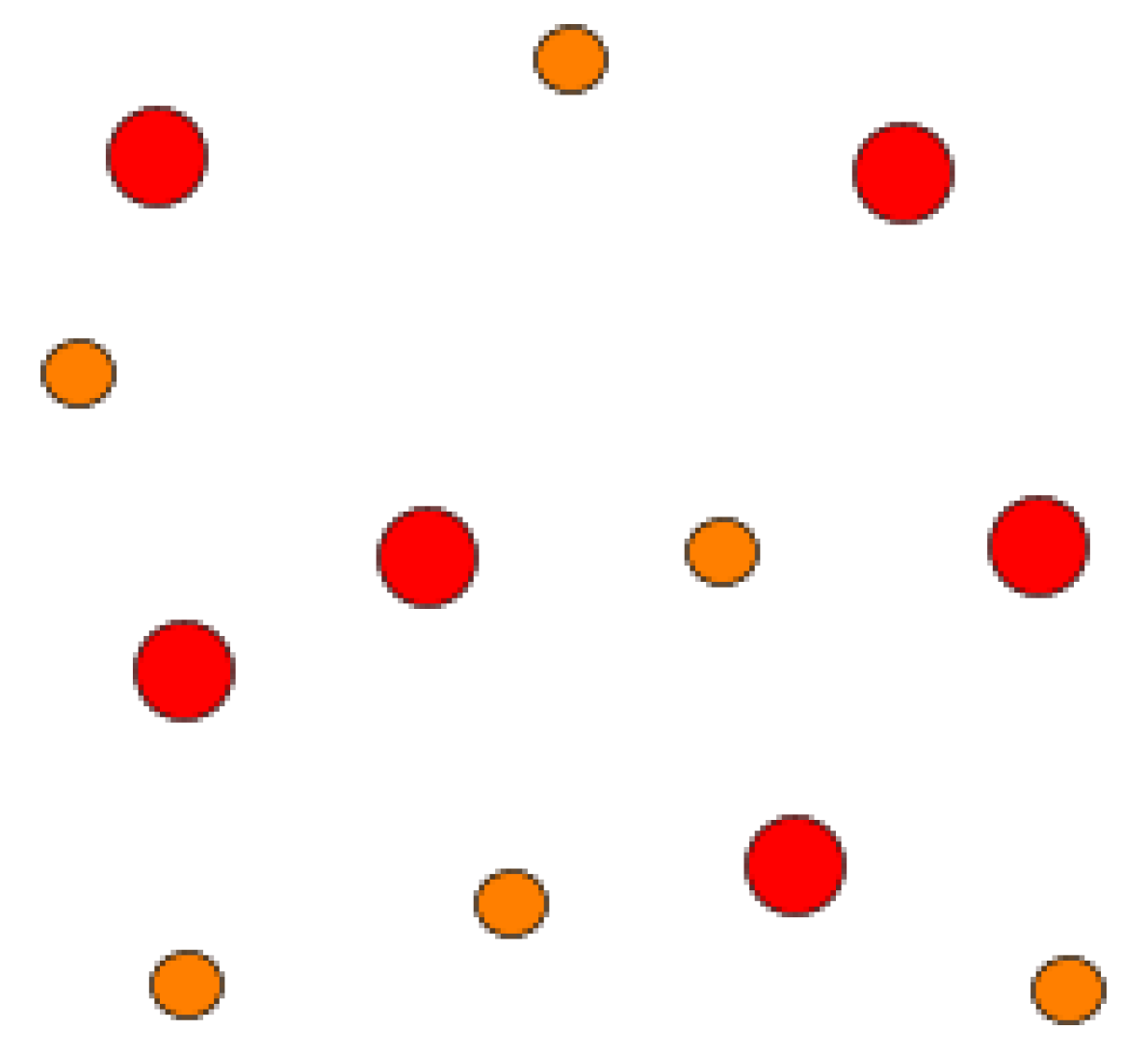
Figure 7. Plasma of protons and electrons, the read circles symbolize protons, while the green circles symbolize electrons.
Preprints 79451 g007
Figure 8. Depicted is the 100 plane of a lattice of table salt N a + C l , blue circles are Sodium positive ions and yellow circles are Chlorine negative ions. The trajectory of relativistic electrons is described in terms of thick black line.
Preprints 79451 g008
Figure 9. A schematic of an elliptical orbit of an electron around a proton.
Preprints 79451 g009
Table 1. Maximal momentum gained by a relativistic motor for three cases of parameters. We assume an extreme case of charge density σ = 3.7 10 3 Coulomb/ m 2 , and current density J 0 = 5 10 7 Ampere/ m 2 .
car rocket size engine giant cube units
a 6 200 1000 m
b 2 10 1000 m
d 1 10 1000 m
w 0.2 0.4 0.4 m
P m e c h 0.3 868 3.1 10 7 kg m/s
Disclaimer/Publisher’s Note: The statements, opinions and data contained in all publications are solely those of the individual author(s) and contributor(s) and not of MDPI and/or the editor(s). MDPI and/or the editor(s) disclaim responsibility for any injury to people or property resulting from any ideas, methods, instructions or products referred to in the content.
Copyright: This open access article is published under a Creative Commons CC BY 4.0 license, which permit the free download, distribution, and reuse, provided that the author and preprint are cited in any reuse.
Prerpints.org logo

Preprints.org is a free preprint server supported by MDPI in Basel, Switzerland.

Subscribe

© 2024 MDPI (Basel, Switzerland) unless otherwise stated