
Submitted:
16 July 2023
Posted:
17 July 2023
You are already at the latest version
Abstract
The extensive utilization of rebar during the construction of the project generates immense rebar waste, leading to increased construction costs and significant greenhouse gas emissions. Various approaches have been explored focusing on the minimization of rebar-cutting waste, such as optimizing cutting patterns, lap splice position, and special-length rebar utilization. Nonetheless, reducing rebar usage by minimizing the number of splices remains uninvestigated. In response to these issues, a two-stage optimization algorithm was developed, prioritizing special-length rebar to achieve near-zero rebar-cutting waste of less than 1% and concurrently reduce rebar usage, thereby promoting sustainable construction practices. The two-stage algorithm presented in this study involves the optimization of the lap splice position for the continuous rebar with a reduction of splices number. Furthermore, it integrates a special-length minimization algorithm for the additional rebars. Applying the algorithm to beam structures in a small-sized factory building project led to a notable reduction of 29.624 tons of rebar, equivalent to 12.31% of the total purchased quantity. Greenhouse gas emissions were reduced by 102.68 tons, and associated costs decreased by USD 30,256. A rebar-cutting waste of 0.99% which is near zero was achieved. These findings highlight the significant potential of the proposed algorithm in reducing rebar waste and facilitating sustainable construction practices. In addition, the application of the proposed algorithm in reinforced concrete construction projects will amplify the associated advantages accordingly.
Keywords:
rebar-cutting waste
; rebar usage
; lap splice
; cutting pattern
; two-stage algorithm
; optimization
1. Introduction
The use of concrete and rebar is responsible for 65% of construction-related greenhouse gas emissions with rebar contributing approximately 60% of the CO2 [1]. Clark and Bradley discovered that rebar generates 872 kg- ECO2/t of embodied CO2, whereas C25/30 concrete emits a comparatively lower amount of 95 kg- ECO2/t [2]. These discoveries emphasize the significant environmental impact posed by rebar worldwide. The Korea Institute of Construction Technology (KICT) [3] defines in their report, the unit CO2 emissions of high-tensile deformed rebar as 3.466-ton-CO2/ton. In response to the massive amount of greenhouse gases that are emitted into the atmosphere, many countries have imposed carbon pricing policies. Following a report issued by the CDP [4], the carbon price for the construction industry is set at USD 35/ton-CO2 whereas the Construction Association of Korea [5] denotes that the price of rebar is $900/ton in their report.
In the construction of reinforced concrete structures, the generation of rebar-cutting waste is an inevitable consequence as the rebars are not manufactured precisely according to the design [6,7]. In the planning stage, the rebar-cutting waste is estimated to be 3-5%; however, construction sites unexpectedly experienced a higher rebar-cutting waste range of 5-8% [6,8,9]. This has resulted in a staggering global rebar-cutting waste estimate of 47 million tons, emitting 16 million tons of greenhouse gases by 2019 [6]. Incorporating the previously mentioned carbon price and rebar price, potential savings in minimizing global rebar-cutting waste could amount to a substantial 43 billion USD. In addition, global rebar consumption has been estimated to reach a record of 947 million tons [6]. Reducing steel material at its source is the most effective strategy for reducing carbon emissions and one of the key objectives of implementing sustainable construction practices [10,11]. Consequently, optimizing rebar-cutting waste and rebar usage which will substantially reduce the carbon footprint is crucial.
Numerous studies on the optimization of rebar-cutting waste have been conducted to this time. Most studies emphasize the utilization of stock length or market length to make a combination that diminishes cutting waste [8,10,12,13,14]. In their study, Porwal and Hewage [15] introduce the concept of special-length combination to optimize rebar-cutting waste and obtain favorable outcomes. In addition to the aforementioned study, several other studies have been conducted to investigate the efficacy of special-length rebar and demonstrate its advantages over market-length rebar [9,15,16,17,18]. However, there is still a lack of studies that attempt to adopt the special length to optimize rebar-cutting waste.
The rebar lap splice position optimization research offers valuable knowledge regarding the minimization of rebar-cutting waste alongside the previously mentioned approaches [8,10,19]. Building design codes suggest that rebars are lapped in the allowable interval area or zones with minimum stress [8]. This research [8,10,19] mostly complies with the lapping zone regulation provided by building codes. The adoption of the lapping zone inhibits the reduction of rebar-cutting waste, resulting in the generation of noticeably high-cutting waste. A recent study conducted by Widjaja et al. [26] reveals that the effectiveness of a rebar lap splice is not dependent on the moment force. Furthermore, the study discovers that lap splicing beyond the designated area is structurally sound. In a separate study, Almeida et al. [20] asserted that the effectiveness of lap splices relies on key factors such as proper concrete cover, adequate confinement by transverse reinforcement, and high tensile strength of the rebar. Hence, the adjustment made to the lap splice position can be considered acceptable.
This study proposes a novel two-stage optimization algorithm to reduce the rebar-cutting waste and rebar usage of beam elements to realize the near-zero waste strategy utilizing the flexibility of lap splice position and implementing sustainable construction. Beams and columns are the most fundamental and commonly used structural element types in a typical structural RC frame, as they support most of the building’s loads [21]. Beam elements are rather more complicated to handle than other structural elements due to the many options regarding reinforcement placement [19]. The study is carried out in the following stage. Initially, the problems and originality are defined. Then, insights and findings from existing studies on the issue of cutting waste are acquired. The heuristic-based two-stage optimization algorithm is then established. Detailed explanations of the market and special length, rebar minimization, lap splice position, building information modeling, the two-stage optimization process, and algorithms are provided. Furthermore, the rebar-cutting waste and rebar usage is investigated further after applying the proposed algorithms to the case study. In addition to rebar-cutting waste, the impacts of rebar-cutting waste minimization on greenhouse gas emissions and rebar cost reduction are analyzed. Finally, the problems, discoveries, results, and potential for future research are discussed.
2. Literature Review
2.1. Rebar Definition in Special and Market Length
Steelworks manufacture and supply special-length rebar at the request of clients or consumers, subject to minimum requirements including minimum quantities and pre-order time [9]. Special-length rebar may include irregular values such as 8.1, 9.4, and 10.6 m. In the context of this study, market-length rebar pertains to specific standard lengths of rebar supplied by the steelworks [7], commonly available in 1 m intervals. An example of the rebar combinations utilizing market length and special length rebar is shown in Figure 1. For example, if the required length of the rebar in cutting pattern 1 is 10.8 m, the cutting waste produced by the 12 m market length is 1.2 m (10%), whereas cutting pattern i produces 0.8 m (6.67%). In contrast, if a special-length rebar of 11.2 m is ordered, cutting pattern 1 generates only 0.4 m (3.6%) of cutting waste while cutting pattern i produces no cutting waste (0%). Thus, this study prioritizes the utilization of special-length rebar to develop the algorithm.
2.2. Rebar Minimization
One of the focuses in the domain of rebar minimization is related to rebar-cutting waste. The issue of cutting waste minimization has been considered a one-dimensional cutting stock problem (1D-CSP). The current practice of identifying cutting patterns in a manner to reduce cutting waste entails a tedious and arduous manual comparison of feasible possibilities observed based on the engineer’s judgment [8,10,19]. Consequently, numerous approaches were proposed to address 1D-CSP problems, with linear programming (LP) and integer programming (IP) being the most prevalent. However, LP might not result in the optimal solution even though it is efficient [19]. Conversely, IP requires a high computational effort to generate a feasible solution [15].
The circumstance led the researchers to establish an approach that addressed the limitations and delivered a better solution. Heuristic algorithms provide faster and more effective solutions than conventional approaches, such as genetic algorithm (GA) and simulated annealing (SA). Khalifa et al. [22] employed a GA to reduce rebar-cutting waste which was validated to provide a better solution than IP. Porwal and Hewage [15] utilized SA, which was verified to generate the optimal rebar combination on a large-scale problem rapidly.
Most of the studies conducted deployed market-length rebar to diminish rebar-cutting waste. In most cases, the required lengths of rebar during the construction of a project are shorter than the standardized market-length rebars. Consequently, the extraction of required rebar lengths from market-length rebars results in inefficient usage, leading to the generation of rebar-cutting waste [7]. Khalifa et al. [22] utilized market-length rebar to reduce the cutting waste in the steelworks, resulting in a 5.15% cutting waste. Khondoker [7] employed the market-length rebar to reduce rebar-cutting waste in RC frames, leading to 2.69% of rebar-cutting waste. Zheng et al. [12] attempt to minimize slab rebar-cutting waste by using market-length rebar, resulting in 14.49% cutting waste. Considering the near-zero cutting waste strategy, the outcomes obtained in these studies remain noticeably high.
In contrast, Porwal and Hewage [15] introduce the concept of the special-length combination to minimize rebar-cutting waste, obtaining a 0.93% cutting waste. Kim et al. [18] employed special-length rebar to minimize cutting waste in the bearing wall, resulting in 0.819% cutting waste. In a study performed by Lee et al. [9], special-length rebar was applied to successfully diminish the cutting waste of RC frames to 0.58%. The mentioned studies confirmed that the utilization of special-length rebar offers a lower rebar-cutting waste rate than market-length.
As cutting waste minimization has been a focus in contributing to sustainable construction practices, there appears to be a lack of attention on minimizing rebar usage as a strategy for fostering sustainability in construction. Considering the enormous global demand for rebar, a reduction in rebar usage would lead to a corresponding reduction of greenhouse gas emissions throughout the project lifecycle. Therefore, this study adopts the heuristic approach to develop a novel approach that aims to significantly reduce rebar-cutting waste and rebar usage in an effort to achieve near-zero cutting waste.
2.3. Lap Splice Position
The provision of rebar lap joints in RC structures is inevitable due to a variety of reasons, including the limited length of the rebar on-site, the need to connect rebars of differing diameters, and transportation problems [24->23]. The most prevalent types of rebar lap joints employed in construction are welded splices, mechanical splices, and lap splices [24]. Lap splicing or conventional lap splice requires the overlap of two parallel bars and has been widely recognized as an efficient and cost-effective method of splicing for decades [25]. Due to the advantages and simplicity offered, this study emphasizes the utilization of conventional lap splices.
Building design codes usually specify a permissible interval instead of a single-point zone for the lap splice position [8]. The design code recommends that the zone be situated in an area with minimal stress and moment. However, the construction sites do not strictly adhere to the lapping zone regulations provided by the building codes, which depend on the moment forces. Widjaja et al. [26] discover that the moment forces do not determine the effectiveness of the rebar lap splice. Gillani et al. [27] inferred that lap splices must have sufficient length to establish an appropriate bond between the concrete and rebar, ensuring the transfer of force from one bar to another. Almedia et al. [20] furthermore asserted that by providing appropriate concrete cover, adequate transverse reinforcement confinement, and high-tensile strength of rebar, the efficacy of lap splicing can be maintained, and lap splice failure can be averted.
In addition, the study conducted by Widjaja et al. [26] provides the following fresh perspectives regarding the lap splice position issue:
- The provision of lap splices beyond the designated area can offer an equal level of structural strength and stability as those within the designated area.
- Adhering to the lapping zone regulations provided by the building codes can pose several challenges on construction sites, such as difficulty in identifying the exact location and tedious labor.
- Several studies that aim for rebar cutting-waste minimization are restricted in their efforts to significantly reduce the cutting waste due to the adherence to the lapping zone regulation.
The adoption of the lapping zone generates noticeably high rebar-cutting waste. Chen and Yang [19] attempted to optimize the lap splice position following the ACI code to reduce the rebar-cutting waste in a continuous beam section and yielded 8.4% of the cutting waste. Employing the lapping zone provided by the code, Nadoushani et al. [8] attempt to optimize the lap splice position in the columns and shear walls. As a result, the effort resulted in 7.2% and 10.6% cutting waste for column and shear walls respectively. Efficient construction practices encourage the placement of lap splices in heavily loaded or high-stressed areas [20,28]. Accordingly, a conventional lap splice could be lapped in the area beyond the designated area subject to the outlined key factors.
2.4. Building Information Modeling (BIM)
Two separate teams, headed by the architects and structural engineers, are involved in the building design phase at the outset of the construction lifecycle of a project. The effectiveness of a sustainable design process is contingent upon the integration of both teams to deliver an optimal and less-waste design. Ineffective cooperation, communication, and integration lead to an inefficient, time-consuming, error-prone, and non-sustainable design [15]. BIM enables stakeholders to collaborate during the building design process to efficiently investigate multiple options [15]. BIM involves defining a design as objects that carry geometry, relationships, and attributes, that can be extracted to generate useful information [29]. In addition, BIM can be utilized in sustainable analysis to reduce waste and consolidate shipments, thereby reducing carbon footprints even further [30]. Several research regarding rebar optimization has integrated the BIM to build a structural model and retrieve rebar information [8,15]. Nadoushani et al. [8] utilized a BIM-based database to identify the optimal cutting pattern that produces the least amount of cutting waste. In the early stages of the project lifecycle, Porwal and Hewage [15] incorporated BIM to optimize the rebar waste. This study employed Autodesk Revit to draw a structural model of the beams and retrieve useful information.
3. Methodology
In summary, by adjusting the lap splice position, a special-length rebar can be generated without cutting. Therefore, this study proposes a heuristic approach-based two-stage optimization algorithm to reduce the rebar-cutting waste and rebar usage, as well as achieve a near-zero cutting waste strategy of beams. Two-stage optimization here refers to lap splice optimization and special-length-priority optimization. Figure 2 depicts the stages of this study, which are described as follows: 1. Model preparation and rebar information collection; 2. Definition of optimization objective and constraints; 3. Reduction in the number of splices prioritizing special-length rebar without cutting; 4. Rebar combination with the cutting pattern. 5. Optimization result analysis considering the rebar-cutting waste, rebar usage, greenhouse gas emissions, and associated cost. If near-zero cutting waste is achieved, the process is terminated after analyzing the rebar cost and greenhouse gas reduction impact. Otherwise, new parameters must be set, reconducting the optimization process.
3.1. Stage 1: Model Preparation and Rebar Information Collection
The structural element analyzed in this study; beams are modeled in BIM-based software. Autodesk Revit will be utilized to model the structures according to the dimensions and rebar arrangements of the beam provided by the shop drawing. The usage of rebar detail at the shop drawing level is not only for dimensional calculation considering anchorage, splice location, and length but also for precise calculation of rebar length taking shape code and bending margin into consideration. The model developed in Revit includes various important information, including the span length of the beam, dimension, position, and reinforcement of structural elements.
British Standard BS8666:2005 [31] rebar shape code is applied to all the rebars in the Revit model, as shown in Figure 3. The British Standard defines the requirements for the dimensioning, scheduling, cutting, and bending of the rebar. In this study, most of the beams comply with the standard shapes built using the Revit family for the automatic calculation of rebar lengths. According to the BS code, rebar shapes that do not adhere to the standard code can be classified as shape code 99, which requires the rebar shape to be drawn with specific dimensions and within the allowed variance. In addition, if there are numerous 99 shape codes, the corresponding rebar sketch must be drawn and alphanumerically appended as 99 (e.g., 99-xxx).
One rebar shape is regarded with shape code 99, prefixed as 99-01. BS8666:2005 provides the equations to calculate the length of the rebar, considering the hook and end projection. Table 1 lists the equation used to calculate the length of rebar in standard shape code and shape code 99s. Autodesk Revit can generate a rebar-cutting list that contains the above-mentioned information for the optimization processes.
3.2. Stage 2: Definition of Optimization Objectives and Constraints
This study seeks to propose a novel two-stage optimization algorithm for optimizing the lap splice position including a reduction in the number of splices in beam elements to realize the near-zero waste strategy, which entails less than 1% of rebar-cutting waste and minimize rebar usage. Therefore, constraints are set for special-length rebar as follows: the minimum length is 6 m and the maximum length is 11.9 m, with 0.1 m increments. In addition, the steelwork defines the minimum quantity of rebar required to purchase special-length rebar and the preorder time. Because each steelwork may define the minimum purchase quantity and preorder time for special-length rebar differently, this study defines the minimum purchase quantity as 50 tons, with a two-month preorder time. The market length available for purchase is 10 m. No minimum order quantity or preorder time is required to purchase market-length rebar, assuming sufficient supply is always maintained.
3.3. Stage 3: Reduction in the Number of Splices Prioritizing the Special-Length Rebar without Cutting
Lap splice position optimization is then carried out following the retrieval of the rebar information. In addition to lap splice optimization, a reduction of the number of splices approach is also integrated into this stage. The rebar information is arranged in descending order for each rebar diameter size. All potential lapping arrangements of main continuous rebars will be identified through optimization. Figure 4 illustrates the typical rebar arrangements in the continuous beams system.
The lapping arrangement in the beam element will be identified using Equations (6) through (13) which are proposed in this study. Equations (1) through (2) are provided by British Standard [32] to determine the tension lap splice length in reinforced concrete structures. It is calculated considering the anchorage (development) length of the rebar .
where is the yield stress of the rebar, is the diameter of the rebar, is the partial safety factor (1.4), is the coefficient dependent on the rebar type (use value of 0.5 for tension rebar and 0.63 for compression rebar), and is the compressive strength of concrete.
As depicted in Figure 5, a continuous beam requires the rebars to be anchored in the column or another beam at both ends. Generally, to anchor, the rebar has to be bent at 90° to create a hook extension height . Equation (3) is used to calculate this type of extension. The total hook anchorage length can be obtained by adding the anchorage length and hook extension, is shown in Equation (4).
The total length of rebar along the continuous beam span is calculated as shown in Equation (5) by adding the length of the continuous beam span with the total hook anchorage length and total rebar lapping length subtracted by the width of the column at both ends of the beam and bending deduction [33]. Equations (6) and (7) are utilized to calculate the total lapping length and bending deduction, respectively.
The total rebar lapping length as presented in Equation (6) can be obtained by adding the result of the number of lap splices () multiplied by the lapping length ().
The required number of special length rebar in Equation (8) is obtained by dividing the total length by the maximum market-length that can be purchased . In addition, the new number of splices can be obtained by subtracting one from the number of special length rebar, as illustrated in Equation (9). Furthermore, the difference between the original splice number and the new number of splices denotes the reduction in number of splices , as shown in Equation (10).
Due to the reduction in the number of splices, the total rebar length should be recalculated. The calculation of the new total rebar length is described in Equation (11).
As demonstrated in Equation (12), the length of special-length rebar can be obtained by dividing the new total rebar length by the number of special-length rebars.
Upon acquiring the length of the special-length rebar, its quantity or weight () then can be calculated through the multiplication of the length of the special-length rebar by the number of special-length rebar and the unit weight of the rebar (), as shown in Equation (13).
The optimization process is conducted in the steps as follows:
- After the rebar information is retrieved, then the lapping length and hook anchorage length of the rebar as described in Equations (1) through (4) is calculated.
- The total length of the rebar then can be obtained utilizing Equations (5) to (7).
- Then, using Equation (8) to (10), calculate the special-length rebar number , special-length rebar number , and special-length rebar number .
- Calculate the new total length of rebar using Equation (11).
- Determine the length of special-length rebar which satisfies Equations (12) and (9).
- After determining the special-length rebar, adjust the rebar lap length if required, then check the adjusted lap splice arrangement.
3.4. Stage 4: Rebar Combination with the Cutting Pattern
- Special -Length-Priority Minimization (SLP)
In this stage, special-length priority optimization is performed utilizing special-length rebar to fulfill the objective function defined in Equation (17) as developed in previous studies [9,18]. This stage focuses on the optimization of additional rebars of the beam to identify the best combination. However, before the optimization process can begin, the precise calculation of the additional rebar’s length should take precedence, as mentioned in Stage 1.
As depicted in Figure 4 above, additional rebars can be divided into two groups, additional top rebars, and additional bottom rebar. Additional top rebars themselves can be distinguished into two, additional top rebars for the end support, and additional top rebars for the mid support. The previous study introduced a precise calculation approach, presented in Equations (14) to (16), for accurately calculating the length of additional rebars [33]. The additional top rebars for both end support can be calculated using Equation (14) considering the hook anchorage length (), beam’s clear span length , additional embedded length , column width at either left or right-support end , and rebar bending deduction ().
The additional top rebars for mid-support length can be obtained considering the beam’s clear span length , additional embedded length , column width at the mid-support end , as shown in Equation (14). If there is a discrepancy in the required number of rebars for the additional top rebar for the mid-support, the smaller number will be prioritized. The remaining rebars will be allocated as additional top rebars for either the left-mid or right-mid position. The length of the relevant rebars can be obtained by using Equation (15) by assigning the and as zero.
The additional bottom rebar for the middle span can be acquired utilizing Equation (16) considering the beam’s clear span length and additional embedded length .
The objective function is fulfilled by minimizing the ratio of cutting waste generated by the special-length rebar . Therefore, the optimization is deployed to search for the most optimum special-length rebar that satisfies the constraints outlined in Equations (18) to (23), hence reducing the rebar-cutting waste.
where is the special-length i, is the length of cutting pattern i acquired by combining multiple demand lengths, is the number of rebar combinations with the same cutting pattern.
The constraints that must be satisfied to fulfill the objective function are described by Equations (18) through (23). First, the length of cutting pattern i is derived by combining multiple demanded rebars which must be equal or less than the special-length rebar , as indicated in Equation (18).
Equation (19) limits the length of special-length rebar to be longer than the minimum length of rebar and cannot exceed the maximum length of rebar to be purchased .
According to Equation (20), the rebar-cutting waste needs to be less than the target rebar-cutting waste .
Then, the total combined special-length rebar quantity must exceed the minimum quantity of special-length rebar to be purchased , as specified in Equation (21).
Finally, Equation (22) addresses the negativity issue, restricting the number of rebar combinations with the same pattern i to an integer value.
- 2.
- Quantity calculation
After the special length and market length with the cutting pattern were identified, the quantity or weight () can be obtained using Equation (23).
where is the identified special-length rebar, is the number of identified special-length rebar, and is the unit weight of rebar.
3.5. Stage 5: Result Analysis
The previous stage generated quantities are further analyzed. If near-zero cutting waste is achieved (<1%), the process is terminated after analyzing the rebar cost and CO2 generated. Otherwise, the constraints should be modified, reconducting the optimization. The cycle is repeated until near-zero cutting waste is achieved.
The required quantity () and purchased quantity of rebars () are obtained. The required quantity refers to the actual used quantity in the construction site, while the purchased quantity refers to the purchased quantity of rebar that the contractor purchased from the steelworks. Then, overall rebar-cutting waste can be obtained by dividing the difference between the required and purchased quantity by the purchased quantity, as described in Equation (24).
Then, the performance of the optimization algorithm is verified by comparing the cutting waste generated by the proposed algorithm to the actual cutting waste acquired by utilizing the market-length rebar. In addition to RCW, the rebar usage is also compared. These cutting wastes are then converted into greenhouse gas emissions (CO2) and associated costs through the unit CO2 emission of rebar and carbon pricing mentioned in the previous section. By reducing rebar-cutting waste and rebar usage, associated rebar cost is reduced. In addition, sustainable construction can be achieved through the reduction of greenhouse gas emissions.
4. Case Study and Verification
4.1. Selection of a Case Project
The beams of a typical RC industrial construction project in Korea are utilized to validate the performance of the proposed algorithm. As summarized in Table 2, the building consists of 2 basement levels and 20 floors above the ground. Furthermore, ultra-high tensile deformed (UHD) rebar grade 600 is used in this project for rebar larger than 16 mm.
The building is 104 m in length and 92 m in width. Each floor is connected with the RC column frames ranging from 3.8 m to 5.6 m up to the 20th floor. The beams of the case building have different dimensions and are reinforced differently. Figure 6 shows a rebar arrangement of the G12 beam as an example. As illustrated in Figure 6, the main bars are divided into a top and a bottom section. Both the top and bottom sections are reinforced with 22 mm diameter rebar. The number of rebars for each beam or girder is summarized in Table 3. More rebar arrangements for the remaining beams can be found in Figure A1 until Figure A7 in Appendix A.
4.2. Application of a Two-Stage Optimization Algorithm
In this study, a two-stage optimization algorithm was applied to beams of the longest continuous beam in the short (X) and long (Y) direction. In addition, the proposed algorithm was applied to F2-F7 floors that have similar beam arrangements. As shown in Figure 7, UHD22 mm diameter rebar was used for the main rebars. The optimization procedure was exclusively performed on the main longitudinal rebar. Due to the transversal reinforcements such as stirrups and ties are generally provided in size than 16 mm, utilization of coiled rebar can significantly reduce the rebar-cutting waste. Thus, stirrups and ties are excluded from this study.
Initially, the lap splice optimization was performed by prioritizing the special length rebar and reducing the number of splices utilizing Equations (6) to (13). Before the optimization, the rebar lapping length was recalculated through Equation (1) to (2), aligned with the BS. A partial safety factor ) of 1.4 and a value of bond coefficient of 0.5 were considered for deformed bars type 2. The concrete compressive strength was 27 MPa and the rebar yield strength was 600 MPa. Hence, the lapping length of the UHD22 rebar was 1300 mm for both the bottom and top sections. It is better to design the beam for both the top and bottom sections in tension to withstand significant lateral forces. In addition, the hook extension height was calculated using Equation (4). Since the regulations provided a range for the extension height, a value commonly used on construction sites was selected, resulting in a hook extension height of , or 230 mm for the UHD22 rebar. Subsequently, the length of anchorage can be calculated using Equation (5). The anchorage length of the UHD22 rebar was 1180 mm. Table 4 and Table 5 summarize the beam and rebar information needed, including more detailed beam information.
Maximum cutting waste has been set at 1%. Lap splice optimization was applied in the following constraints: the minimum length of the special-length rebar is 6 m, and the maximum length is 11.9 m, with 0.1 m increments. The minimum quantity (weight) of the special length was set at 50 tons. The rebar to be optimized was the longitudinal rebar of 22 mm diameter. The lap splice optimization with the reduction of splices number was initially conducted on the continuous rebars. However, the minimum requirement constraint, particularly the minimum quantity limits the reduction rate on the rebar-cutting waste to higher than 1%. Therefore, the minimum quantity was set lower than the initial 50 tons to 30 tons. Table 6 summarizes the results, providing the special-length rebar without a cutting pattern.
According to Table 6, the special lengths without cutting obtained by the proposed algorithm are 11.3 and 11.8 m. The total quantity required and purchased quantity were 146.140 and 146.832 tons, respectively with a waste rate of 0.472%. The generated waste rate refers to the loss rate due to the rounding up function imposed as special length should be purchased in 0.1 m increments. As no cutting process was involved, the rebar lapping length should be adjusted. Figure 7 illustrates the adjustment of rebar lapping length for beams in the long direction.
In the following stage, the optimized rebar combination that generates the least amount of rebar-cutting waste, was obtained by employing Equations (14) to (23). The minimization was conducted on the additional rebars. The constraints set on the special-length rebar in this step were identical to those set in the previous step. The results of the minimization are presented in Table 7.
After minimization, the special length rebars obtained were 6.6 and 11.9 m in length, as shown in Table 7. The total weight and purchased weight are 84.263 and 85.802 tons respectively, resulting in a cutting waste of 1.793%. The rebar-cutting waste was significantly influenced by the diverse lengths and inherent characteristics of additional rebars, resulting in a higher rate of rebar-cutting waste generation. The total quantity of special-length rebar purchased in the third and fourth stages exceeded the minimum quantity requirement of 30 tons.
Table 8 details the overall cutting waste rate generated by the proposed algorithm. The total quantity of rebar required for construction was 208.900 tons, and 210.992 tons of special-length rebar had to be purchased. One diameter of rebar was used, and a total cutting waste of 0.99% was generated. As shown in Table 8, the utilization of special-length rebar has a significant impact on reducing rebar-cutting waste. Special length without cutting accounts for 59.33% of the total rebar, followed by the special length with cutting at 40.67%.
4.3. Verification of the Proposed Algorithm
4.3.1. Rebar-Cutting Waste and Rebar Usage Analysis
A comparative analysis was performed to evaluate the effectiveness of the proposed algorithm by comparing the quantities of rebars in the original and optimized state. The original design of the case building utilized a 10 m of market length to combine all the required rebars. Table 9 summarizes the comparison result regarding the rebar-cutting waste. As shown in Table 9, the original designs and market-length rebar utilization resulted in 27.138 tons of rebar-cutting waste, equal to 11.28% of the purchased quantity, whereas the proposed algorithm only generates 2.092 tons or 0.99% of waste. Consequently, leading to a significant reduction of 25.046 tons or 92.30% of the rebar-cutting waste.
In terms of rebar usage, the original design required the purchase of 240.616 tons of rebar. Conversely, 210.992 tons of rebar should be purchased by the proposed algorithm, resulting in a reduction of 29.624 tons or 12.31% rebar. By utilizing special-length rebar, optimizing lap splice position, and reducing splice numbers, a significant reduction in rebar-cutting waste and rebar usage is achieved.
4.3.2. Constraint Impact
In the previous section, the proposed algorithm was applied with the following constraints in mind: the minimum length of the special length rebar is 6 m, and the maximum length is 11.9 m, with 0.1 m increments. A minimum quantity (weight) of 50 tons was set for the special length. As mentioned earlier, each steelwork may have its requirements for purchasing rebar of a special length. This section applies the proposed algorithm to the same case study under the following constraints: the maximum rebar-cutting waste rate is 1%, the minimum length of the special length rebar is 6 m, and the maximum length is 11.9 m, with increments of 0.1 m. The minimum quantity (weight) of each diameter and length of the special length rebar was set at 50 tons. However, this particular set of constraints did not yield any solutions. Hence, the maximum waste rate was increased to 2%. Table 11 outlines the overall rate of cutting waste generated by the proposed algorithm.
The total quantity of rebars required to construct the building was 208.900 tons, and 212.085 tons of special-length rebar had to be purchased. As noticed in Table 10, all the purchased weight of the special-length rebar exceeds the minimum quantity requirements of 50 tons. The proposed algorithm results in 1.50% rebar-cutting waste. The implication arises from the minimum requirement of 50 tons, indicating that rebar-cutting waste exceeding 1% was still generated, thereby resulting in the inability to attain near-zero cutting waste, as previously mentioned. Compared to the previous section, 1.50% of cutting waste was notably higher. This condition indicates that the current constraints, particularly the minimum quantity requirement, affected the performance of the proposed algorithm significantly.
4.3.3. Greenhouse Gas (CO2) Emission and Cost Reduction Effects
The proposed algorithm was then further analyzed to verify the contribution to sustainable construction. Table 11 provides the greenhouse gas emission and associated cost reduction after applying the proposed algorithm. In a report published by the Korean Institute of Construction Technology (KICT) [3], the unit CO2 emission of high-tensile deformed rebar was defined to be 3.466 ton-CO2/ton. Incorporating 3.446 ton-CO2/ton, the greenhouse gas emissions from the original and proposed quantities were 833.98 tons and 731.30 tons, respectively. Consequently, 102.68 tons of CO2 can be reduced. Thus, the proposed algorithm has a significant impact on sustainable construction.
The associated cost reduction effect was verified by converting the saved rebar quantity and CO2 emission to a monetary value. In terms of the rebar material cost, the rebar unit price of USD 900/ton published by the Construction Association of Korea [5] was considered, reducing the rebar cost by USD 26,662. In terms of the carbon-associated cost, the carbon price of USD 35/ton-CO2 provided by the CDP [4] in their report for the construction industry was considered, resulting in a USD 3,594 reduction in carbon costs. When both cost reductions were tallied, a total savings of USD 30,256 were achieved. Therefore, it is confirmed that the proposed algorithm significantly reduces both greenhouse gas emissions and associated costs, hence contributing to the implementation of sustainable construction. Greater greenhouse gas emissions and cost reductions are expected when the proposed algorithm is applied to entire horizontal structural members of a building.
4. Discussion
The building code’s requirements for the lapping zone often do not consider the conditions and workability of construction sites, resulting in increased use of rebar and, consequently, higher waste. Furthermore, the authors contend that the lapping zone regulation should be lifted. The author’s previous investigation [26] presents a novel perspective suggesting that providing lap splices beyond the designated zone has no impact on structural stability. Hence, the proposed algorithm which does not adhere to the lapping zone regulation was able to minimize the rebar-cutting waste to 0.99%, reaching near zero.
Previous studies have predominantly emphasized rebar-cutting waste minimization to promote sustainable construction practices. However, there has been noticeably limited attention on rebar usage minimization. Chen and Yang [19] underscored that the design of the continuous reinforcement should provide as fewer splices as possible. In this study, the reduction of splice numbers and special-length rebar utilization was proposed to significantly reduce the purchased rebar quantity that will be used in the construction. As a result, a notable reduction of 12.31% in the overall purchased rebar quantity for construction was achieved, highlighting a significant reduction in rebar usage.
This study proves that the utilization of special-length rebar can significantly reduce rebar-cutting waste and rebar usage. Nonetheless, not all construction professionals are aware of this fact. Thus, there is an obstacle to implementing this strategy. Given that just a few researchers attempted to utilize the special length, it is necessary to make greater efforts to encourage its use to achieve sustainable construction faster.
In addition, most steelworks have purchasing requirements for special-length rebars, such as a minimum order of 50 tons and a two-month advance preorder time. Consequently, the use of special-length rebar is limited to large-scale construction projects. Furthermore, the previous section revealed that the performance of the proposed algorithm relied on the special-length rebar requirements. If the steelworks can provide special-length rebar with greater accessibility, for instance by reducing the minimum order quantity and preorder time. Thereby, enabling smaller construction projects to utilize the special-length rebar. Hence, the utilization of special-length rebar is expected to become more prevalent.
5. Conclusions
This study proposed a two-stage optimization algorithm to reduce rebar-cutting waste and rebar usage, achieving a near-zero cutting waste strategy. The heuristic-based algorithm developed on these two stages: (1) optimization of lap splice position for main continuous rebars to acquire special length without cutting pattern and reduction of splices number; and (2) special-length-priority minimization with the cutting pattern for the additional rebars. The proposed algorithm was applied to the beams of a small factory building. The rate of cutting waste for each stage is 0.44%, and 1.79%, resulting in a total cutting waste of 0.99%. Hence, near-zero cutting waste was achieved. In addition, the proposed algorithm reduced 29.624 tons of rebar, equivalent to 12.31% of the total purchased rebar, and reduced 102.68 tons of greenhouse gas emissions and associated costs of USD 30,256. The results emphasize the lap splice position optimization, splices number reduction, and special-length rebar, which were demonstrated to significantly reduce rebar-cutting waste and rebar usage, contributing to sustainable construction practices. Due to the purchasing requirements for special-length rebars by the steelworks, the proposed algorithm is limited to large-scale construction projects. Thus, greater effort is required to encourage the steelworks to ease the purchasing requirements of special-length rebar, which will contribute to the faster adoption of special-length and the implementation of sustainable construction. Furthermore, the application of the proposed algorithm in construction projects that comprise multiple continuous beam structures will augment the corresponding advantages to a greater extent.
Author Contributions
Conceptualization, S.K..; methodology, D.D. and S.K.; validation, S.K.; formal analysis, D.D.; investigation, D.D.; resources, S.K.; data curation, S.K.; writing—original draft preparation, D.D.; writing—review and editing, D.D. and S.K.; supervision, S.K..; project administration, S.K.; funding acquisition, S.K. All authors have read and agreed to the published version of the manuscript.
Funding
This research was supported by the National Research Foundation of Korea (NRF) grant funded by the Republic of Korea government (MOE) (No. 2022R1A2C2005276). .
Data Availability Statement
Data sharing is not applicable to this article.
Conflicts of Interest
The authors declare no conflict of interest. The funders had no role in the design of the research; in the collection, analyses, or interpretation of data; in the writing of the manuscript, or in the decision to publish the results.
Appendix A
Figure A1.
Rebar details and arrangement for the G6A beam.
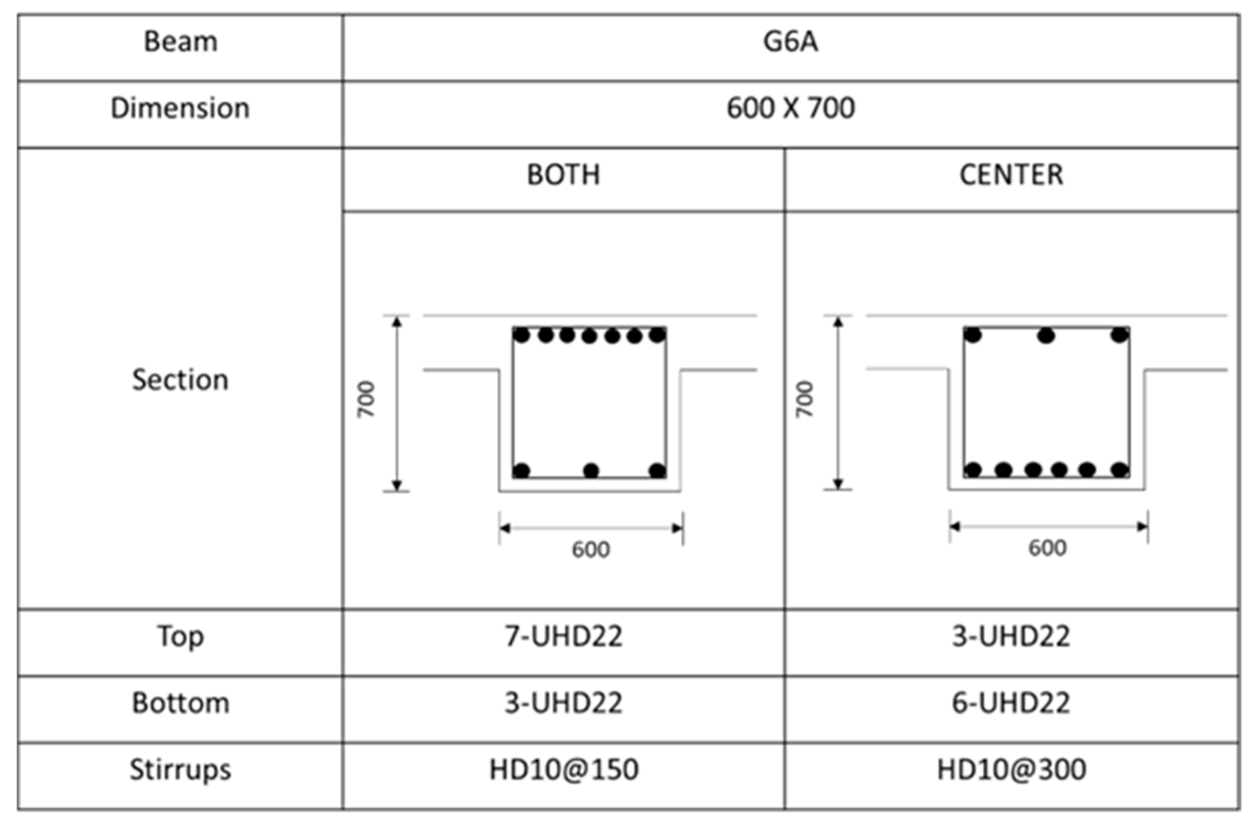
Figure A2.
Rebar details and arrangement for the G6 beam.
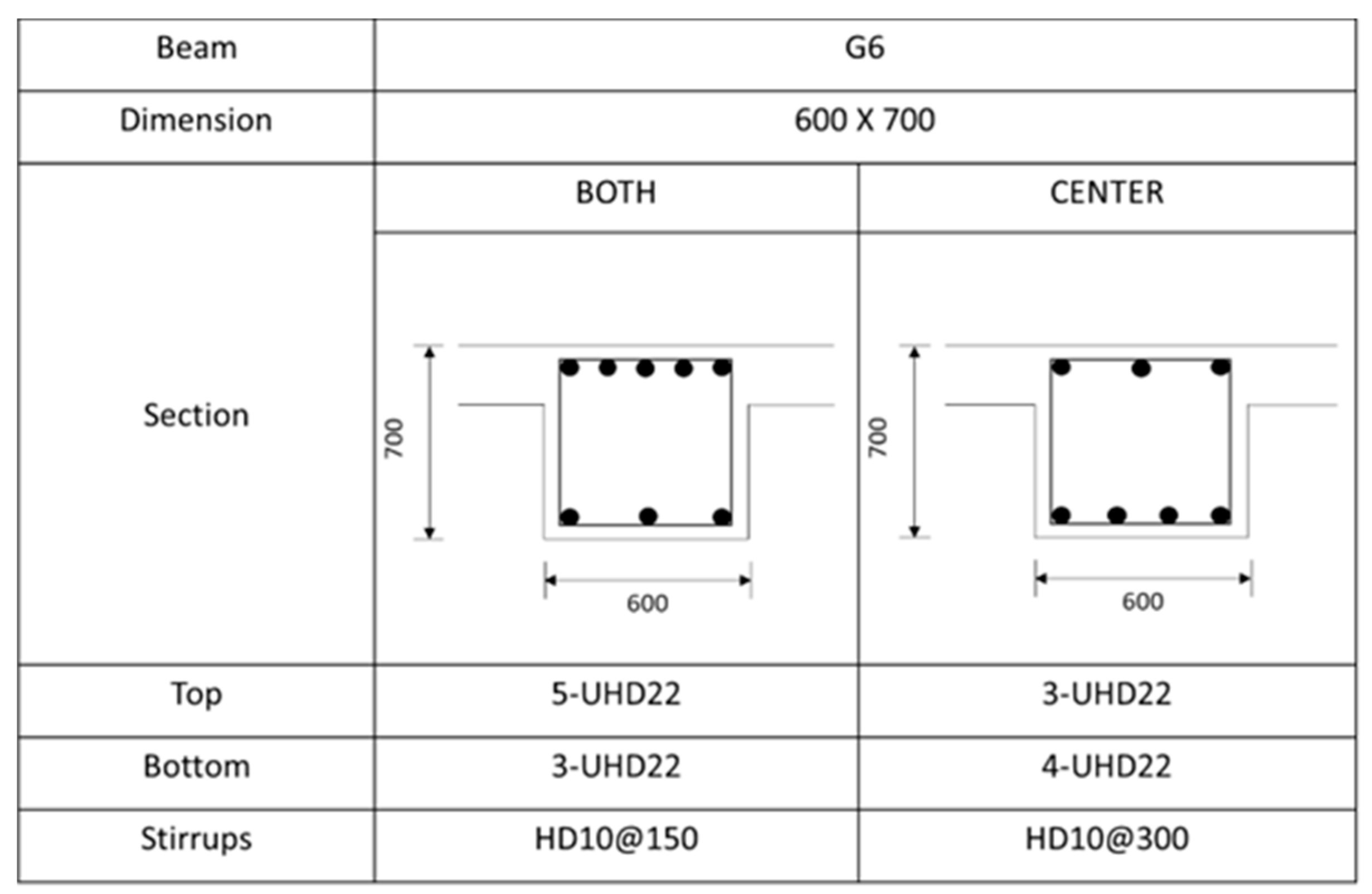
Figure A3.
Rebar details and arrangement for the G11A beam.
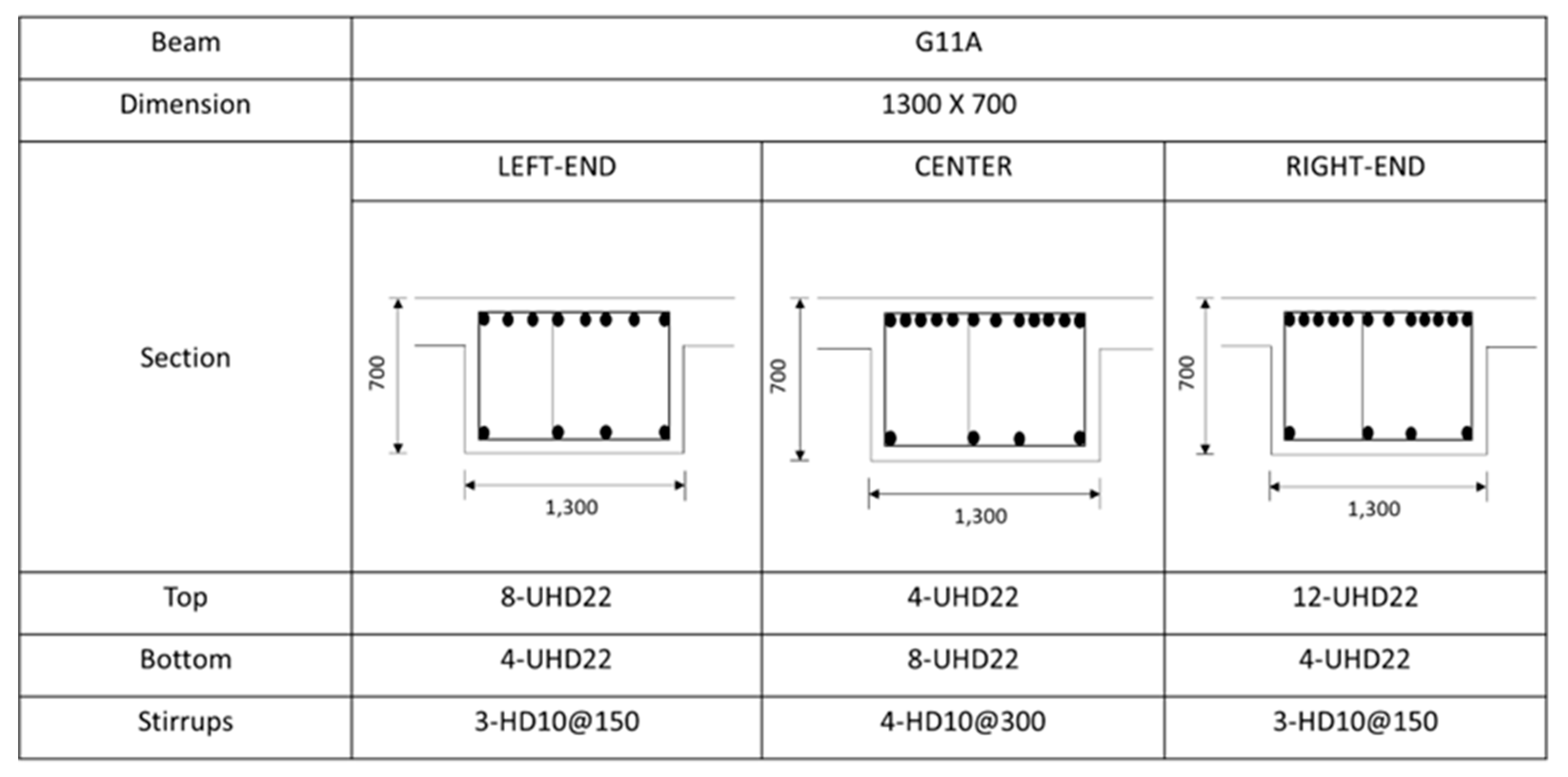
Figure A4.
Rebar details and arrangement for the G11 beam.
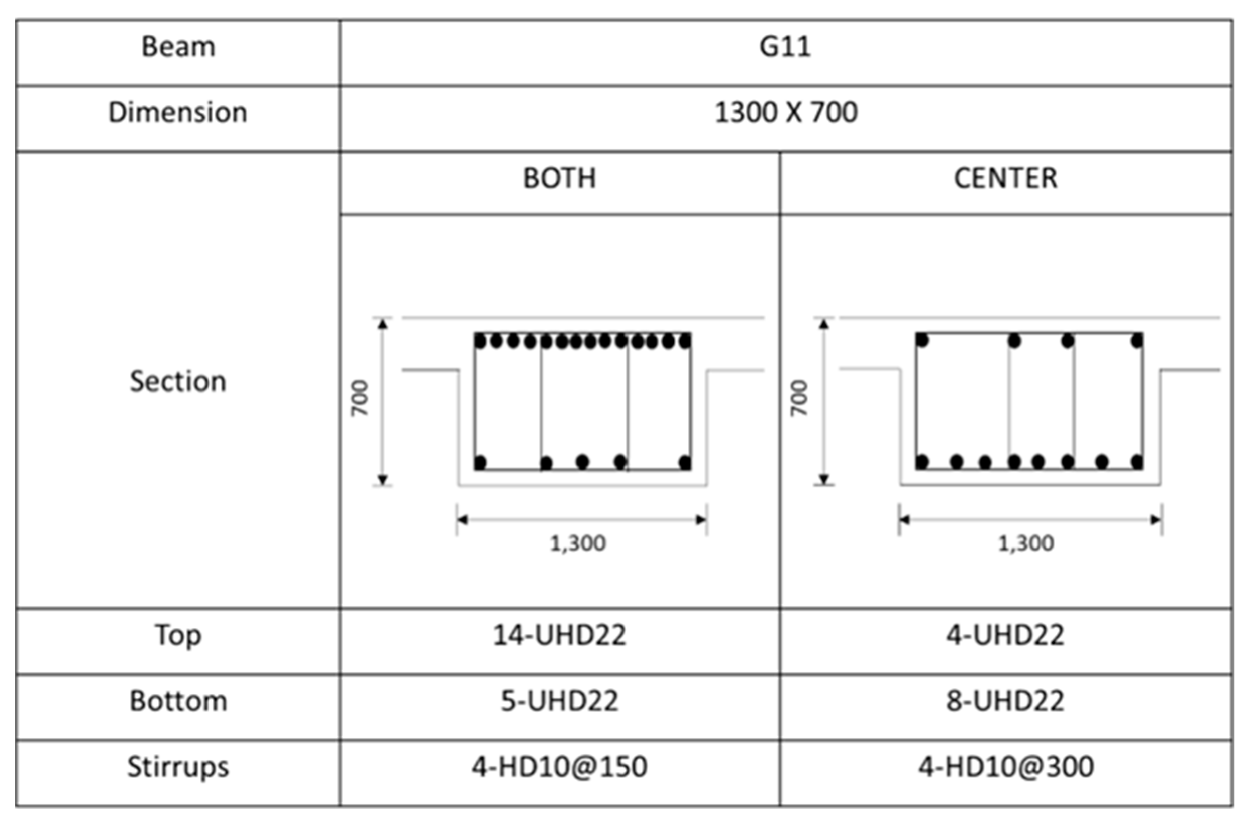
Figure A5.
Rebar details and arrangement for the G12A beam.
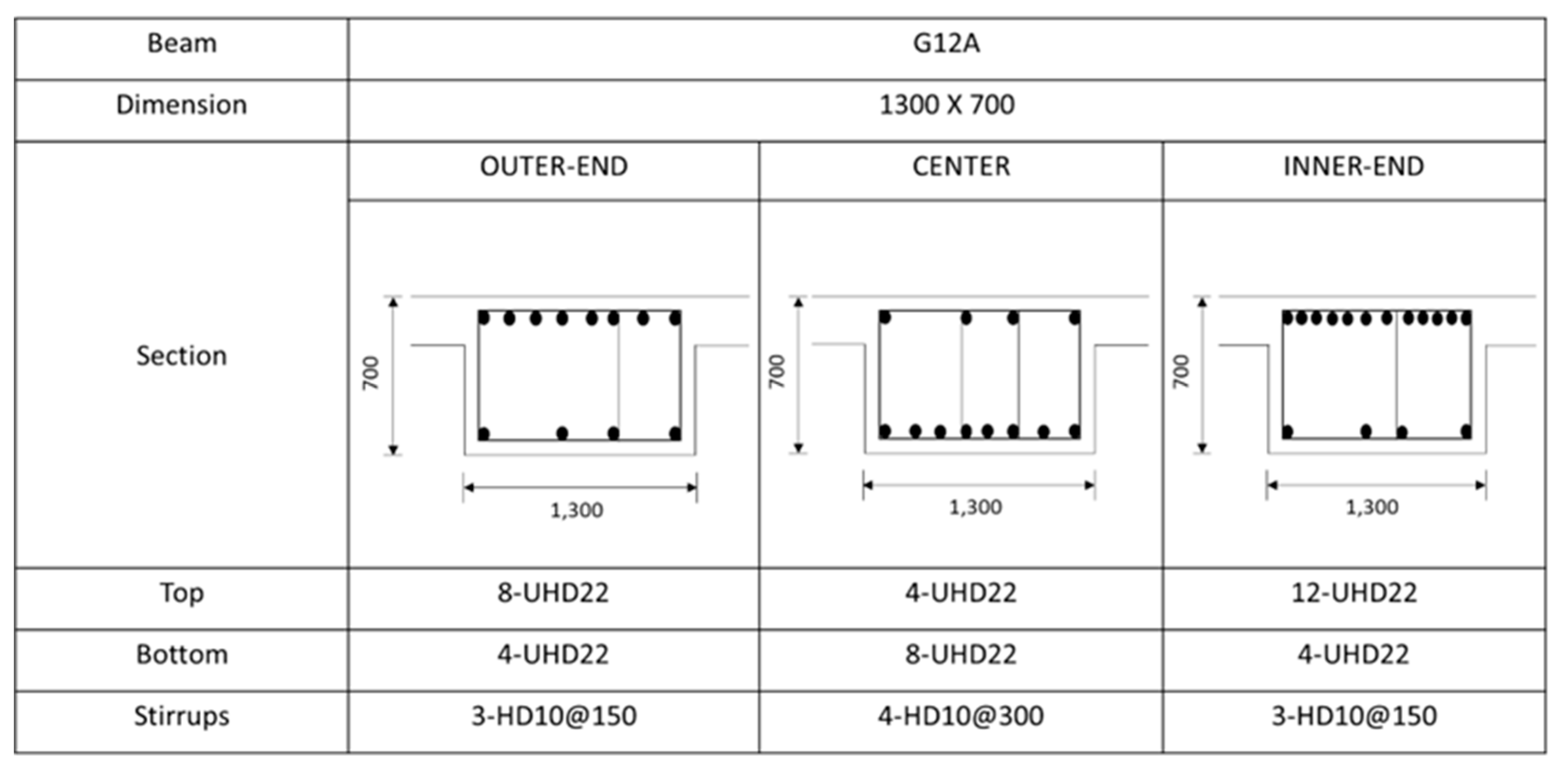
Figure A6.
Rebar details and arrangement for the G13 beam.
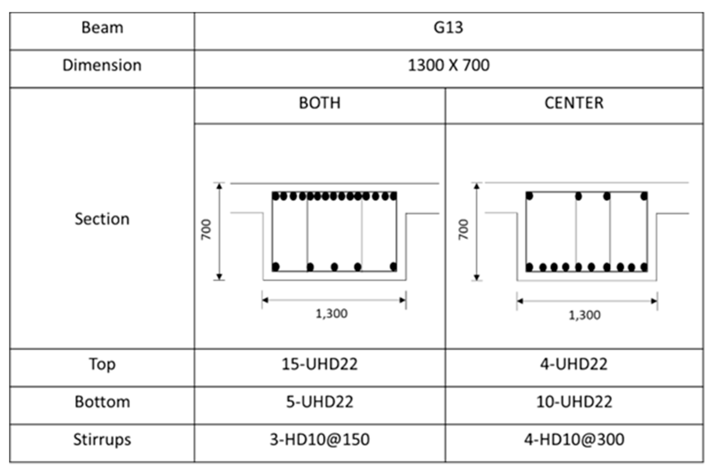
Figure A7.
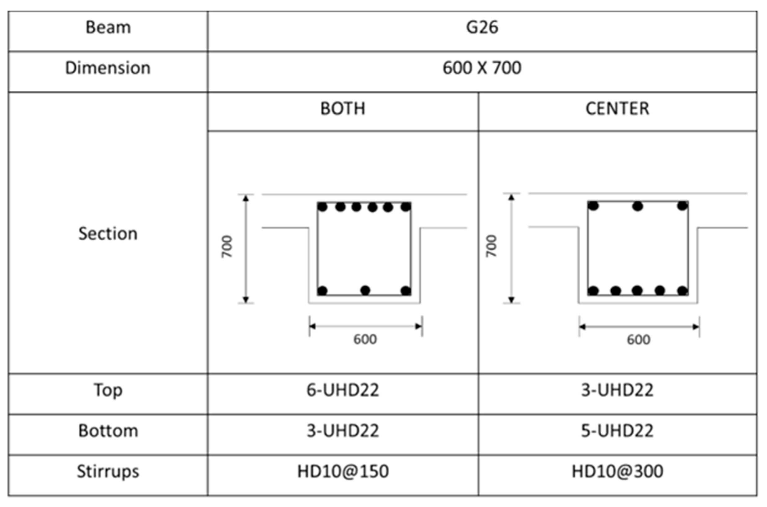
Rebar details and arrangement for the G26 beam.
References
- Kim, K.; Jeon, Y.; Park, Y.J.; Park, S. Sustainable Anti-Tank Obstacle System Applying Civil-Military Cooperation in Highly Urbanized Areas. Sustainability 2022, vol. 14 no. 19, p. 12715. [CrossRef]
- Clark, D.; Bradley, D. Information Paper – 31: Embodied Carbon of Steel Versus Concrete Buildings, Cundall Johnston & Partners LLP: Newcastle, UK, 2013; p.4.
- Korea Institute of Construction Technology (KICT). The Environmental Load Unit Composition and Program Development for LCA of Building: The Second Annual Report of the Construction Technology R&D Program. Korean Institute of Construction Technology, Korea, 2004. Available online: https://scienceon.kisti.re.kr/srch/selectPORSrchReport.do?cn=TRKO201000018952 (accessed on 17 January 2023).
- CDP. Putting a Price on Carbon. The State of Internal Carbon Pricing by Corporates Globally. Available online: https://www.cdp.net/en/research/global-reports/putting-a-price-on-carbon (accessed on 17 January 2023).
- Construction Association of Korea. Construction on Hold As Material Prices Go Through the Roof. 2022. Available online: https://koreajoongangdaily.joins.com/2022/04/22/business/industry/Inflation/20220422165447730.html (accessed on 17 January 2023).
- Kwon, K.; Kim, D.; Kim, S. Cutting Waste Minimization of Rebar for Sustainable Structural Work: A Systematic Literature Review. Sustainability 2020, vol. 13 no. 11, p. 5929. [CrossRef]
- Md. T.H. Khondoker. Automated Reinforcement Trim Waste Optimization in RC Frame Structures using Building Information Modeling and Mixed-Integer Linear Programming. Automation in Construction 2021, vol. 124, p. 103599. [CrossRef]
- Nadoushani, Z.S.M.; Hammad, A.W.; Xiao, J.; Akbarnezhad, A. Minimizing Cutting Wastes of Reinforcing Steel Bars Through Optimizing Lap Splicing within Reinforced Concrete Elements. Construction and Building Materials 2018, vol. 185, p. 600-608. [CrossRef]
- Lee, D.; Son, S.; Kim, D.; Kim, S. Special-Length-Priority Algorithm to Minimize Reinforcing Bar-Cutting Waste for Sustainable Construction. Sustainability 2020, vol. 12, no. 15, p. 5950. [CrossRef]
- Nadoushani, Z.S.M.; Hammad, A.W.; Akbarnezhad, A. A Framework for Optimizing Lap Splice Positions within Concrete Elements to Minimize Cutting Waste of Steel Bars. In Proceedings of the 33rd International Symposium on Automation and Robotics in Construction (ISARC 2016), Auburn, AL, USA, 21 July 2016. [Google Scholar] [CrossRef]
- Ma, Z.; Zhao, Q.; Cang, T.; Li, Z.; Zhu, Y.; Hei, X. An Intelligent Optimization Method of Reinforcing Bar Cutting for Construction Site. Computer Modeling in Engineering & Sciences 2023, vol. 134, no. 1, pp. 637-655. [CrossRef]
- Zheng, C.; Lu, M. Optimized Reinforcement Detailing Design for Sustainable Construction: Slab Case Study. Procedia Engineering 2016, vol. 145, pp. 1478-1485. [CrossRef]
- Zheng, C.; Yi, C.; Lu, M. Integrated Optimization of Rebar Detailing Design and Installation Planning for Waste Reduction and Productivity Improvement. Automation in Construction 2019, vol. 101, pp.32-47. [CrossRef]
- Zubaidy, S.; Dawood, S.Q.; Khalaf, I.D. Optimal Utilization of Rebar Stock for Cutting Processes in Housing Project. Int. Adv. Res. J. Sci 2016, vol. 3, pp. 189–193. [CrossRef]
- Porwal, A.; Hewage, K.N. Building Information Modeling–Based Analysis to Minimize Waste Rate of Structural Reinforcement. J. Constr. Eng. Manage 2012., vol. 138, no. 8, pp. 943–954. [CrossRef]
- Kim, D.; Lim, C.; Liu, Y.; Kim, S. Automatic Estimation System of Building Frames with Integrated Structural Design Information (AutoES). Iran J Sci Technol Trans Civ Eng 2020, vol. 44, no. 4, pp. 1145–1157. [CrossRef]
- Kim, S.K.; Kim, M.H. A Study on the Development of the Optimization Algorithm to Minimize the Loss of Reinforcement Bars. J. Archit. Inst. Korea 1991, vol. 7, pp. 385–390.
- Kim, S.K.; Hong, W.K.; Joo, J.K. Algorithms for Reducing the Waste Rate of Reinforcement Bars. Journal of Asian Architecture and Building Engineering 2004, vol. 3, no. 1, pp. 17–23. [CrossRef]
- Chen, Y.H.; Yang, T.K. Lapping Pattern, Stock Length, and Shop Drawing of Beam Reinforcements of an RC Building. J. Comput. Civ. Eng. 2015, vol. 29, no. 1, p. 04014028. [CrossRef]
- Almedia, J.P.; Prodan, O.; Tarquini, D.; Beyer, K. Influence of Lap Splices on the Deformation Capacity of RC Walls. I: Database Assembly, Recent Experimental Data, and Findings for Model Development. J. Struct. Eng. 2017, vol. 143, no. 12, p. 04017156. [CrossRef]
- Mangal, M.; Cheng, J.C.P. Automated Optimization of Steel Reinforcement in RC Building Frames Using Building Information Modeling and Hybrid Genetic Algorithm. Automation in Construction 2018, vol. 90, pp. 39–57. [CrossRef]
- Khalifa, Y; Salem, O.; Shahin, A. Cutting Stock Waste Reduction Using Genetic Algorithms. In Proceedings of the 8th Annual Conference on Genetic and Evolutionary Computation, Seattle, WA, USA; 2006; pp. 1675-1680. [CrossRef]
- Dabiri, H.; Kheyroddin, A.; Dall’Asta, A. Splice Methods Used for Reinforcement Steel Bars: A State-of-the-Art Review. Construction and Building Materials 2022, vol. 320, p. 126198. [CrossRef]
- Najafgholipour, M.A.; Dehghan, S.M.; Khani, M.; Heidari, A. The Performance of Lap Splices in RC Beams Under Inelastic Reversed Cyclic Loading. Structures 2018, vol. 15, pp. 279–291. [CrossRef]
- Swami, P.S.; Javheri, S.B.; Mittapalli, D.L.; Kore, P.N. Use of Mechanical Splices for Reinforcing Steel. In Proceedings of the National Conference on Innovative Trends in Engineering and Technology, Solapur, Maharashtra, India, 2016; pp. 1–6. Available online: https://www.neliti.com/publications/426567/use-of-mechanical-splices-for-reinforcing-steel#cite (accessed on 17 January 2023).
- Widjaja, D.D.; Rachmawati, T.S.N.; Kwon, K. ; Kim. S. Investigating Structural Stability and Constructability of Buildings Relative to the Lap Splice Position of Reinforcing Bars. J. Korea Inst. Build. Constr. 2023, vol. 23, no. 3, pp. 315-326. [CrossRef]
- Gillani, A.S.M.; Lee, S.G.; Lee, S.H.; Lee, H. , Hong, K.J. Local Behavior of Lap-Spliced Deformed Rebars in Reinforced Concrete Beams. Materials 2021, vol. 14, no. 23, p. 7186. [CrossRef]
- Haefliger, S.; Kaufmann, W.; Thoma, K. Modelling the Load-Deformation Behaviour of Lap Splices with the Tension Chord Model. Engineering Structures 2022, vol. 252, p. 113606. [CrossRef]
- Rajendran, P.; Gomez, C.P. Implementing BIM for Waste Minimisation in the Construction Industry: A Literature Review. In Proceedings of the 2nd International Conference of Management (ICM), Langkawi, Kedah, Malaysia, 2012; pp. 557–570. Available online: https://www.academia.edu/download/34243119/043_191_2ndICM2012_Proceeding_PG0557_0570.pdf (accessed on 17 January 2023).
- Azhar, S.; Brown, J. BIM for Sustainability Analyses. International Journal of Construction Education and Research 2009, vol. 5, no. 4, pp. 276–292. [CrossRef]
- British Standard Institute. Scheduling, Dimensioning, Bending, and Cutting of Steel Reinforcement for Concrete-Specification, 1st ed.; British Standard Institute: London, UK, 2020; pp. 1–32. [Google Scholar]
- British Standard Institute. Structural Use of Concrete: Code of Practice for Design and Construction-Part 1, 2nd ed.; British Standard Institute: London, UK, 1997; pp. 1–150. [Google Scholar]
- Widjaja, D.D. ; Kim. D.; Kim. S. Development of an Automatic Quantity Estimation for Beam Rebar. J. Korea Inst. Build. Constr. 2023, vol. xx, no. xx, pp. xxx.
Figure 1.
Rebar combination using market and special-length rebar: (a) Combination cases of market lengths rebar; (b) Combination cases of special-length rebars (Source: Lee et al. [9]).
Figure 1.
Rebar combination using market and special-length rebar: (a) Combination cases of market lengths rebar; (b) Combination cases of special-length rebars (Source: Lee et al. [9]).
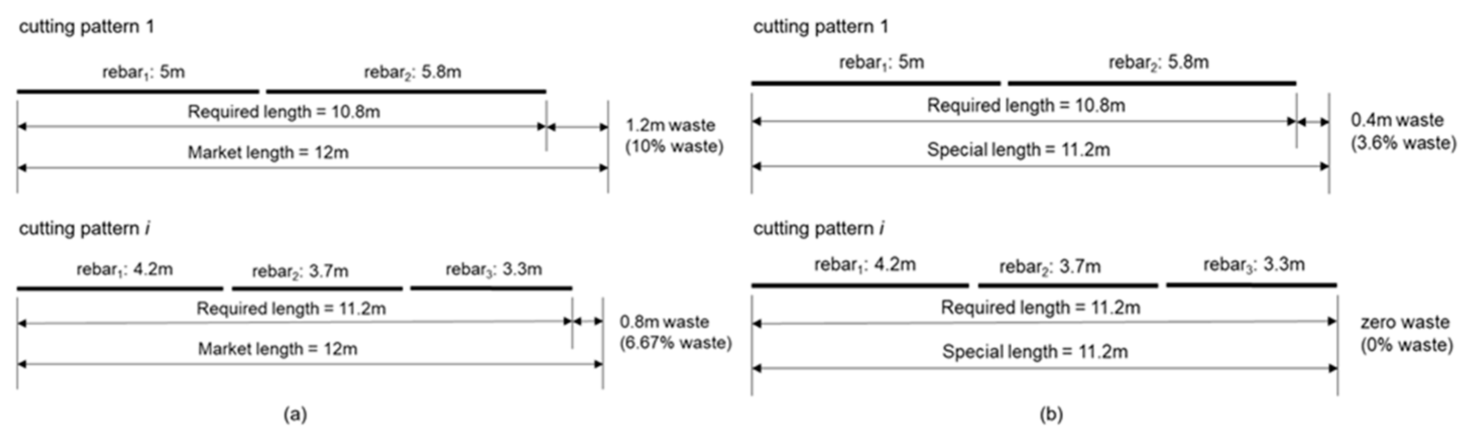
Figure 2.
Two-stage optimization algorithm framework.
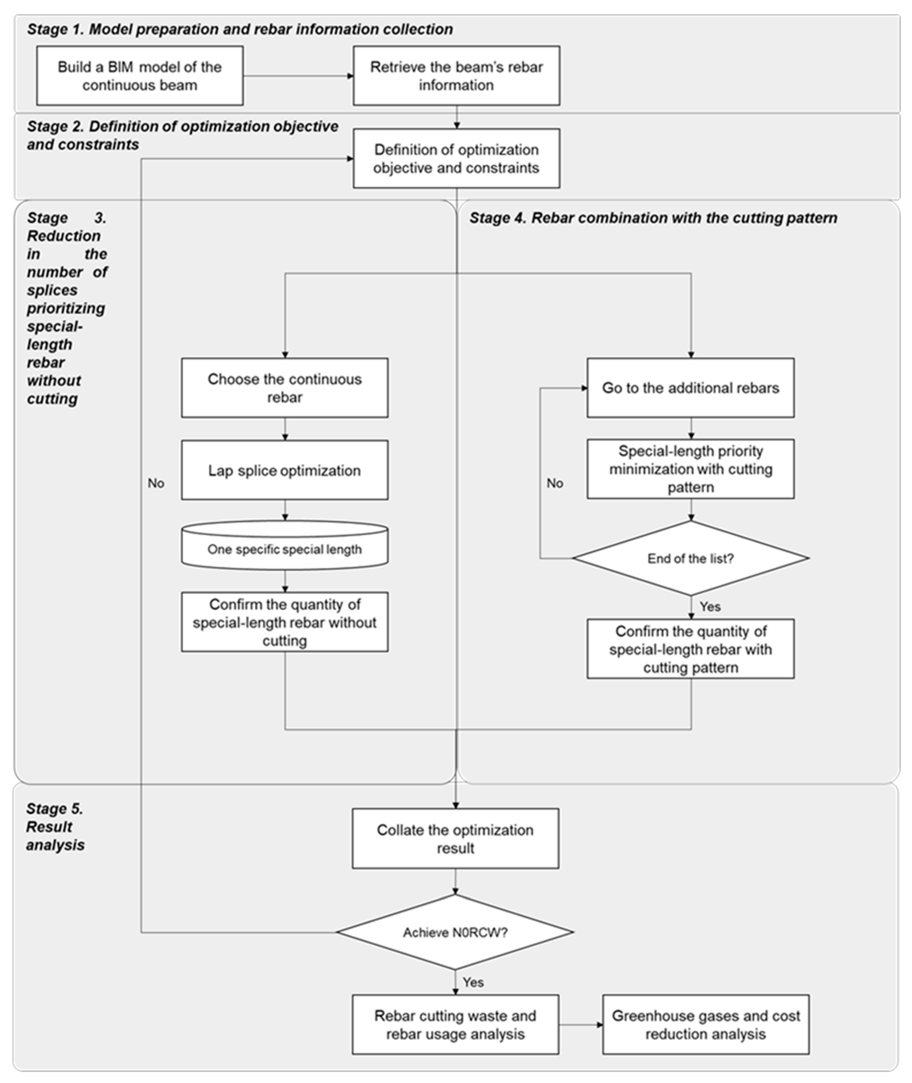
Figure 3.
BS standard shape code for rebar.
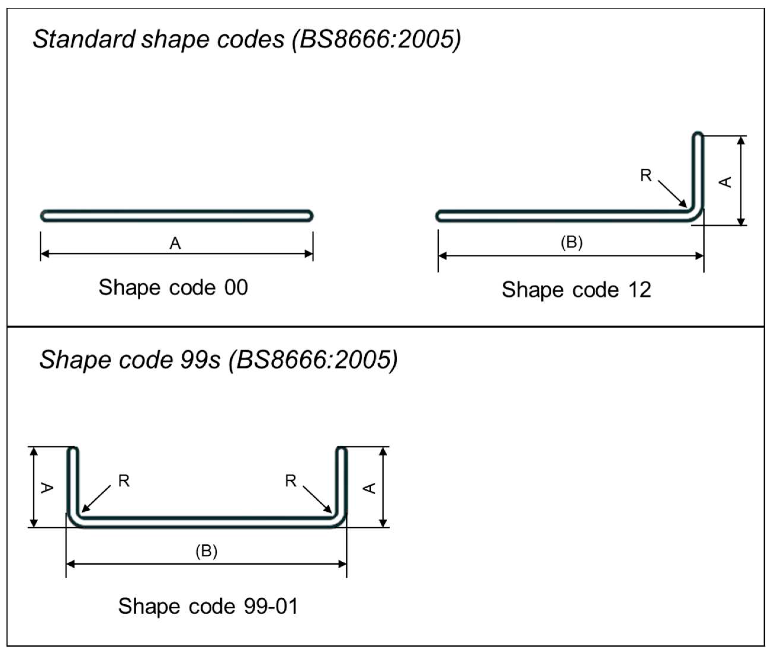
Figure 4.
Typical beam rebar arrangement.
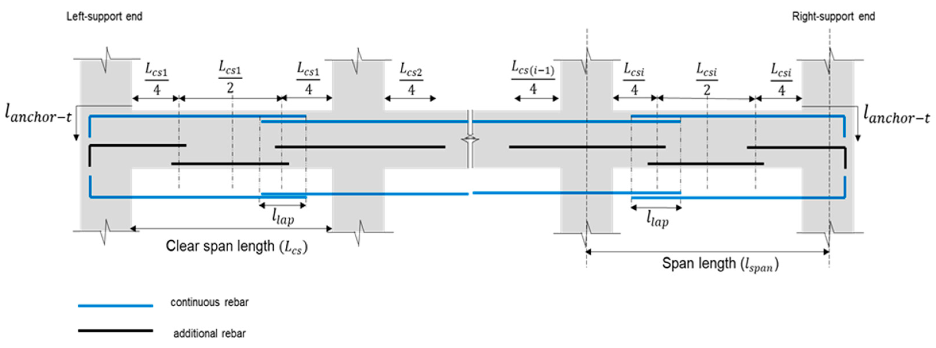
Figure 5.
Standard hook anchorage.
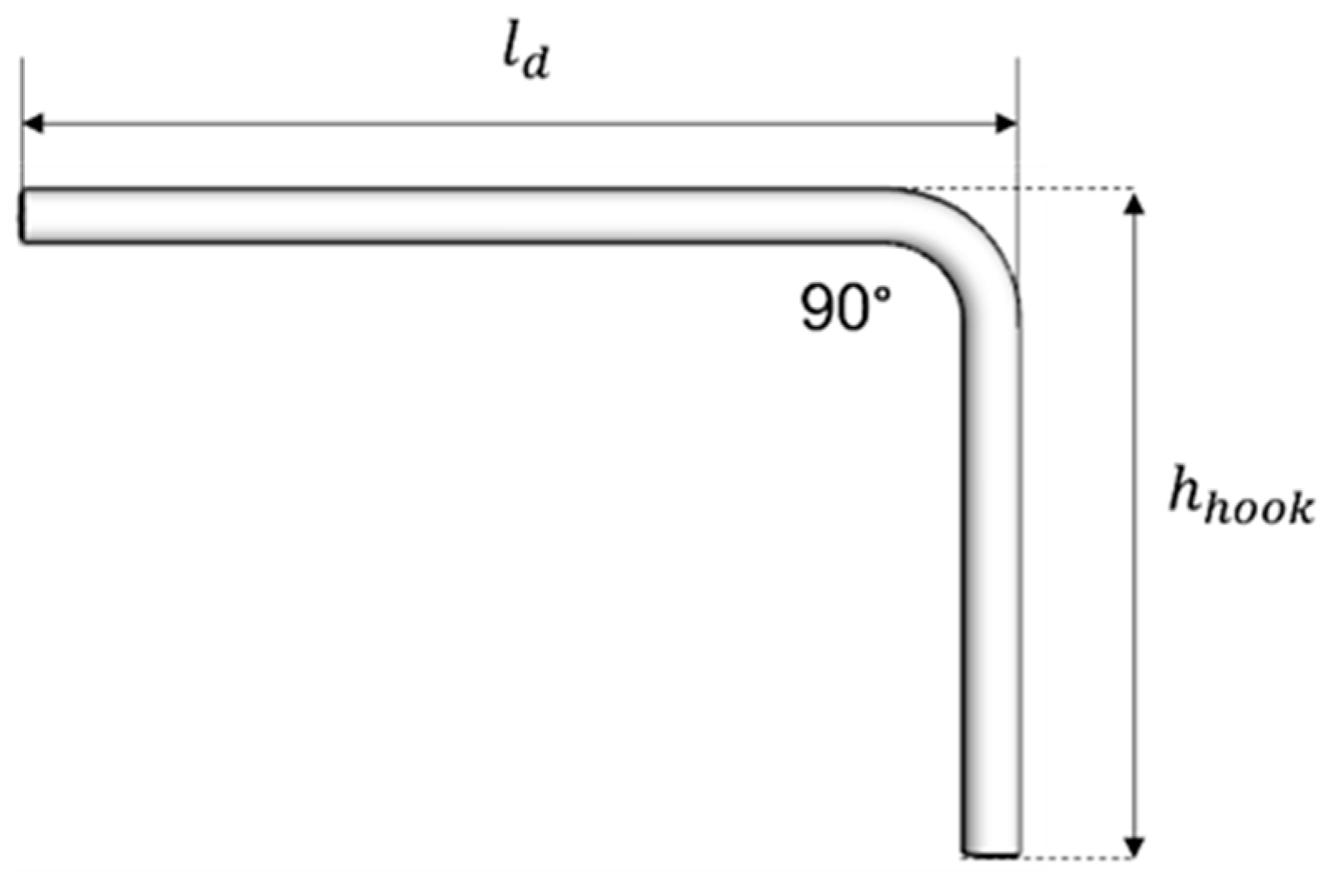
Figure 6.
Rebar details and arrangement of the G12 beam.
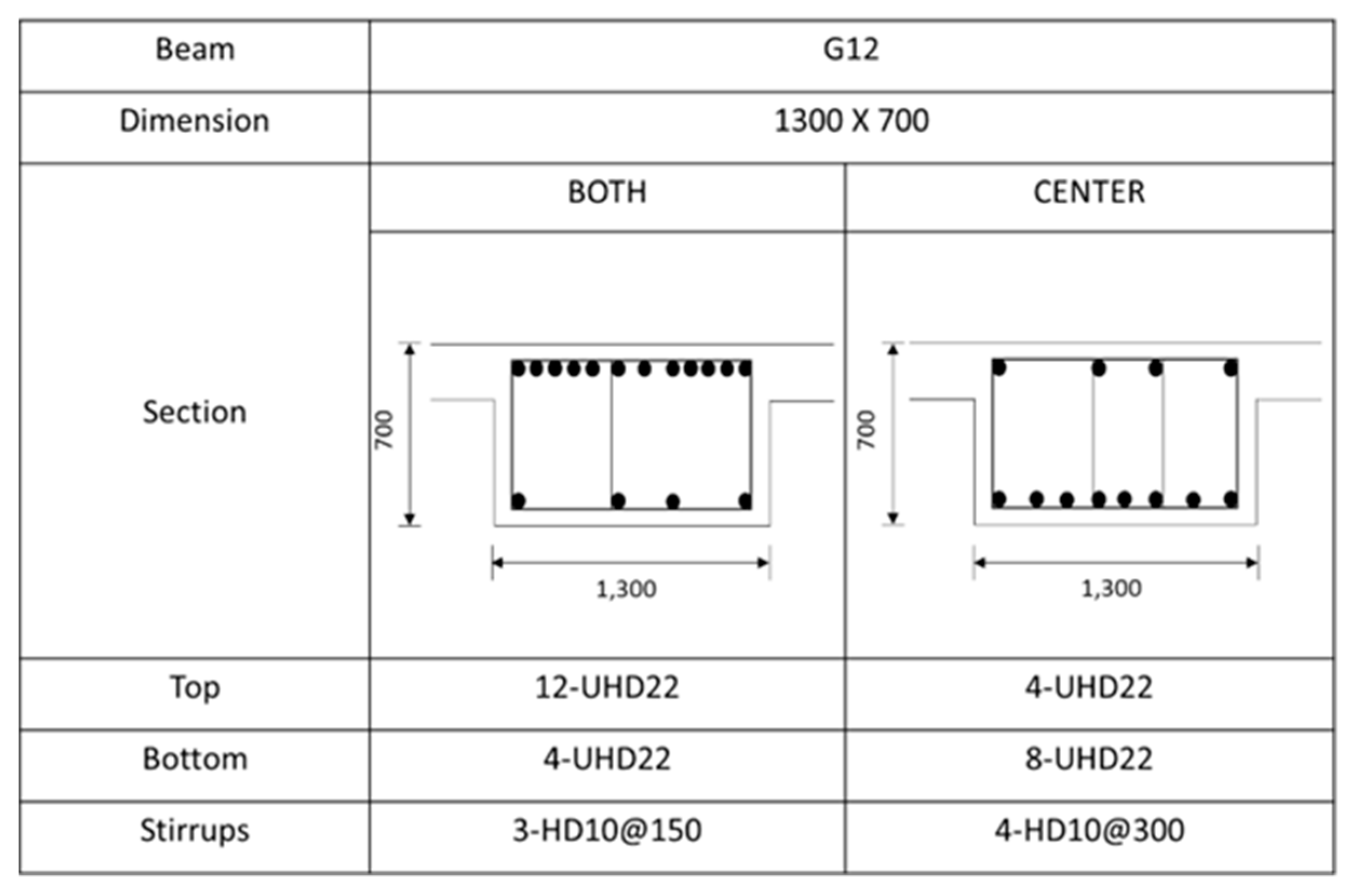
Figure 7.
Rebar-lapping arrangement: (a) Original rebar-lapping arrangement; (b) Optimized rebar-lapping arrangement.
Figure 7.
Rebar-lapping arrangement: (a) Original rebar-lapping arrangement; (b) Optimized rebar-lapping arrangement.
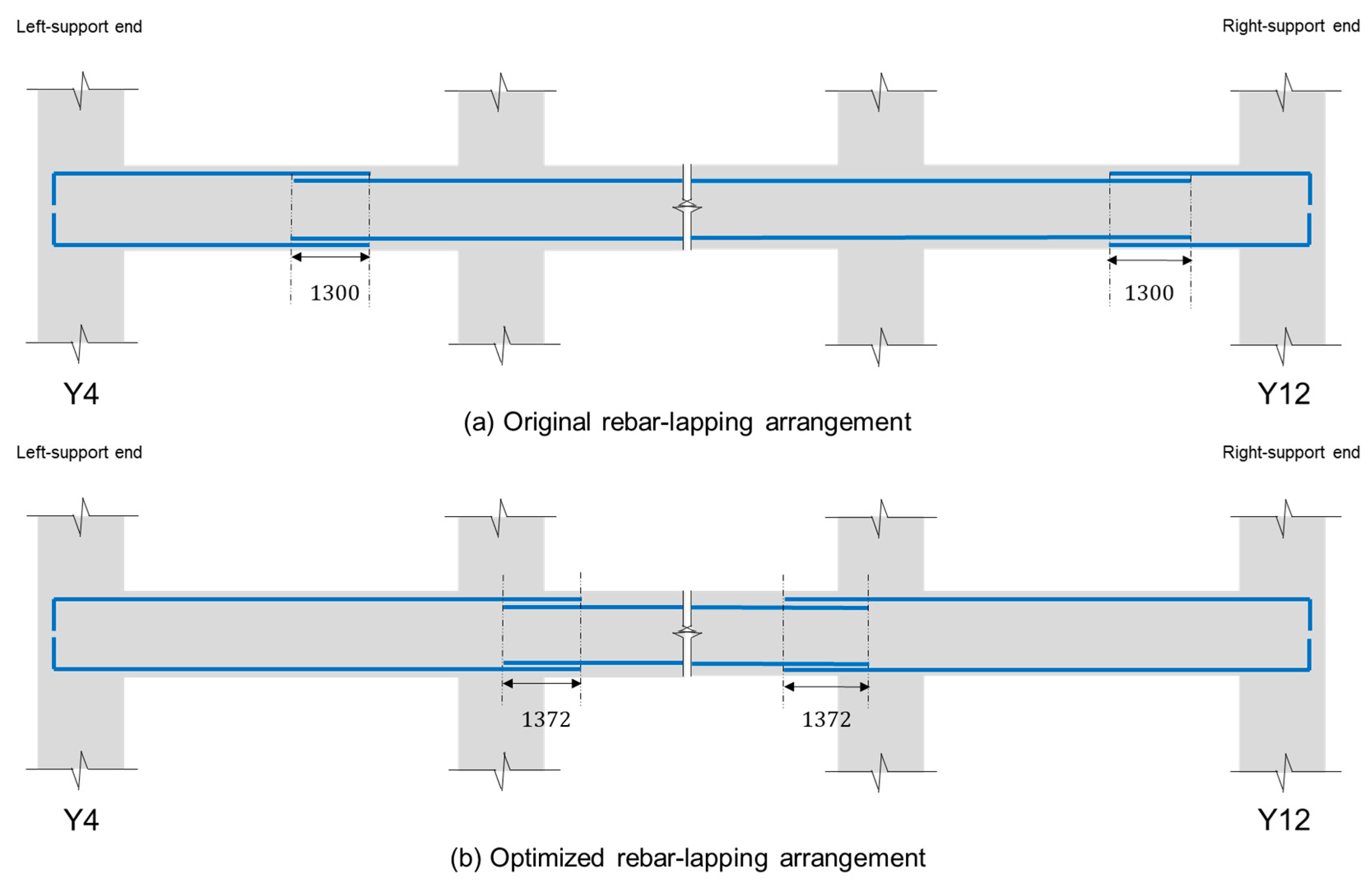

Table 1.
Equations of the used standard and 99s rebar shape codes.
| Standard Shape Code | Equation | Shape Code 99s | Equation |
|---|---|---|---|
| 00 | A | 99-01 | 2A + B – 0.86R – 2.4db |
| 12 | A + (B) – 0.43R – 1.2db | - | - |
Table 2.
Description of the case study project.
| Description | Contents |
|---|---|
| Location | Korea |
| Building type | Highrise buildings for small-sized factories |
| Site area | 10,720 m2 |
| Building area | 6,317 m2 |
| Total floor area | 72,916 m2 |
| Number of floors | B2-F20 |
| Structure | Reinforced Concrete (RC) |
| Concrete strength (fcu) | 27 MPa |
| Rebar yield strength (fy) | >D16, fy = 600 MPa |
Table 3.
Number of rebars in each beam arrangement.
| Beam | Top | Bottom | ||||||
|---|---|---|---|---|---|---|---|---|
| Left End | Center | Right End | Continuous | Left End | Center | Right End | Continuous | |
| G11A | 8 | 4 | 12 | 4 | 4 | 8 | 4 | 4 |
| G11 | 14 | 4 | 14 | 4 | 5 | 8 | 5 | 4 |
| G12 | 12 | 4 | 12 | 4 | 4 | 8 | 4 | 4 |
| G13 | 15 | 4 | 15 | 4 | 5 | 10 | 5 | 4 |
| G12A | 8 | 4 | 12 | 4 | 4 | 8 | 4 | 4 |
| G6A | 7 | 3 | 7 | 3 | 3 | 6 | 3 | 3 |
| G6 | 5 | 3 | 5 | 3 | 3 | 4 | 3 | 3 |
| G26 | 6 | 3 | 6 | 3 | 3 | 5 | 3 | 3 |
Table 4.
Beam and rebar information.
| Description | X Direction Beam | Y Direction Beam |
|---|---|---|
| Numbers of span in relevant direction | 7 spans | 8 spans |
| Total length of span (∑lspan) | 62,700 mm | 69,600 mm |
| Column width at the left-support end (Wl) | 800 mm | 1100 mm |
| Column width at the right-support end (Wr) | 1000 mm | 1000 mm |
| Beam depth (D) | 700 mm | 700 mm |
| Concrete cover (c) | 50 mm | 50 mm |
| Beam effective depth (d) | 639 mm | 639 mm |
| Rebar diameter (db) | 22 mm | 22 mm |
| Lapping/splicing length (lap) | 1300 mm | 1300 mm |
| Tension hook anchorage length (lanchor_t) | 1180 mm | 1180 mm |
| Rebar unit weight (wrebar) | 2.984 kg/m | 2.984 kg/m |
| Rebar bending deduction (bmargin) | 59.51 mm | 59.51 mm |
Table 5.
Detailed beam information.
| Grid | Beam | Span Length (lspan) | Clear Span Length (Lcs) | Column Width at the Left-Support of a Beam (Wi) | Column Width at the Right-Support of a Beam (Wi+1) |
|---|---|---|---|---|---|
| X3-X4 | G11A | 9300 | 8500 | 800 | 800 |
| X4-X5 | G11 | 9300 | 8400 | 800 | 1000 |
| X5-X6 | G12 | 8400 | 7400 | 1000 | 1000 |
| X6-X7 | G12 | 8400 | 7400 | 1000 | 1000 |
| X7-X8-1 | G13 | 10200 | 9200 | 1000 | 1000 |
| X8-1-X9-1 | G12 | 8700 | 7700 | 1000 | 1000 |
| X9-1-X11 | G12A | 8400 | 7500 | 1000 | 800 |
| Y4-Y5 | G6A | 10200 | 9100 | 1100 | 1100 |
| Y5-Y6 | G6 | 8400 | 7700 | 1100 | 600 |
| Y6-Y7 | G6 | 8400 | 7800 | 600 | 600 |
| Y7-Y8 | G6 | 8400 | 7800 | 600 | 600 |
| Y8-Y9 | G6 | 8400 | 7800 | 600 | 600 |
| Y9-Y10 | G6A | 10200 | 9400 | 600 | 1000 |
| Y10-Y11 | G26 | 7800 | 6900 | 1000 | 800 |
| Y11-Y12 | G26 | 7800 | 6900 | 800 | 1000 |
Table 6.
Special-length rebar without a cutting pattern.
| Diameter (mm) | Special Length (m) | Number of Rebars | Total Quantity (ton) | Purchased Quantity (ton) | Waste Rate (%) |
|---|---|---|---|---|---|
| UHD22 | 11.3 | 1680 | 60.130 | 60.265 | 0.225- |
| 11.8 | 2520 | 86.010 | 86.567 | 0.644 | |
| Total | 146.140 | 146.832 | 0.472 |
Table 7.
Special-length rebar with cutting patterns.
| Diameter (mm) | Special Length (m) | Number of Rebars | Total Quantity (ton) | Purchased Quantity (ton) | Waste Rate (%) |
|---|---|---|---|---|---|
| UHD22 | 6.6 | 1575 | 30.686 | 31.601 | 2.90% |
| 11.6 | 1537 | 53.577 | 54.201 | 1.15 | |
| Total | 84.263 | 85.802 | 1.79% |
Table 8.
Summary of the total rebar-cutting waste.
| Description | Waste Rate (%) | Total Quantity (ton) | Purchased Quantity (ton) | Coverage (%) | Cutting Waste (ton) |
|---|---|---|---|---|---|
| Special length without cutting | 0.44% | 124.637 | 125.190 | 59.33% | 0.553 |
| Special length with cutting | 1.79% | 84.263 | 85.802 | 40.67% | 1.539 |
| Total | 0.99% | 208.900 | 210.992 | 100% | 2.092 |
Table 9.
Comparison of original and optimized rebar quantities.
| Description | Total Quantity (ton) | Purchased Quantity (ton) | Cutting Waste (ton) | Cutting Waste (%) |
|---|---|---|---|---|
| Original (O) | 213.478 | 240.616 | 27.138 | 11.28 |
| Proposed (P) | 208.900 | 210.992 | 2.092 | 0.99 |
| Reduction (O-P) | 4.578 | 29.624 | 25.046 | 10.29 |
| Reduction rate (O-P)/P | 2.15% | 12.31% | 92.30% | 91.23% |
Table 10.
Constraint impact on the overall rebar-cutting waste.
| Diameter (mm) | Special Length (m) | Number of Rebars | Total Quantity (ton) | Purchased Quantity (ton) | Waste Rate (%) |
|---|---|---|---|---|---|
| Special length without the cutting pattern | |||||
| UHD22 | 11.3 | 1680 | 60.130 | 60.265 | 0.23% |
| 11.8 | 1890 | 64.507 | 64.925 | 0.64% | |
| Total | 124.637 | 125.190 | 0.44% | ||
| Special length with cutting pattern | |||||
| UHD22 | 11.9 | 2402 | 84.263 | 86.895 | 3.03% |
| Total | 84.263 | 86.895 | 3.03% | ||
| Overall | 208.900 | 212.085 | 1.50% | ||
Table 11.
Greenhouse gas emission and associated cost reduction effect.
| Description | Quantity (ton) | CO2 Quantity (ton) | Rebar Cost (USD) | Carbon Cost (USD) | Total Cost (USD) |
|---|---|---|---|---|---|
| Original (O) | 240.616 | 833.98 | 216,555 | 29,190 | 245,745 |
| Proposed (P) | 210.992 | 731.30 | 189,893 | 25,596 | 215,489 |
| Reduction (O-P) | 29.624 | 102.68 | 26,662 | 3,594 | 30,256 |
Disclaimer/Publisher’s Note: The statements, opinions and data contained in all publications are solely those of the individual author(s) and contributor(s) and not of MDPI and/or the editor(s). MDPI and/or the editor(s) disclaim responsibility for any injury to people or property resulting from any ideas, methods, instructions or products referred to in the content. |
© 2023 by the authors. Licensee MDPI, Basel, Switzerland. This article is an open access article distributed under the terms and conditions of the Creative Commons Attribution (CC BY) license (http://creativecommons.org/licenses/by/4.0/).
Copyright: This open access article is published under a Creative Commons CC BY 4.0 license, which permit the free download, distribution, and reuse, provided that the author and preprint are cited in any reuse.


