Preprint
Article

Intelligent IoT-enabled Ankle Brace: Enhancing Mobility and Safety

Altmetrics

Downloads

193

Views

92

Comments

0

Submitted:

14 July 2023

Posted:

17 July 2023

You are already at the latest version

Alerts
Abstract
This research focuses on the development of a foot-worn device to assist individuals with limited mobility in walking. The device aims to reduce the risk of accidents by closely moni-toring the wearer's movements and detecting potential hazards. It incorporates sensors, in-cluding the MPU6050 gyro sensor and KY-031 vibration sensor, to track the wearer's walking behavior. In case of abnormalities, such as falls, the device triggers an auditory alert and noti-fies the caregiver via LINE Notify. The system is controlled by the Node MCU ESP8266, enabling seamless integration with the Internet of Things (IoT). The objective of this study is to design an IoT system for medical assistance. The researchers created a prototype of a smart ankle device capable of detecting falls and sending notifications to the user's smartphone. The effectiveness of the notification system was evaluated using the Line Notify application. Re-sults demonstrated a successful detection of falls in 48 out of 50 trials, with two instances of false alarms during normal walking. The overall efficiency of the smart ankle device was 98%. In summary, the proposed smart ankle device demonstrates promising potential for var-ious applications in fall detection and safety alert systems. Further improvements and collab-orations with healthcare experts are recommended to enhance its performance and make it commercially viable. The device's connectivity and responsiveness to IoT systems are vital aspects to be considered. Future research should aim to develop additional features in collab-oration with physiotherapists and healthcare professionals to meet user requirements. The de-vice holds significant benefits in terms of fall detection and safety alerts, and efforts should be made to enhance its durability, robustness, and commercialization prospects.
Keywords: 
Subject: Engineering  -   Other

1. Introduction

Physical therapy is recognized as a professional discipline within the realm of health sciences, contributing significantly to the maintenance of individuals' health and well-being. Its scope encompasses a comprehensive spectrum of activi-ties aimed at promoting, preventing, treating, and rehabilitating aberrant move-ment patterns that adversely impact physical functionality. This specialized field of physical therapy is further delineated into distinct branches, namely: 1) Cardio-vascular and Pulmonary Physical Therapy, 2) Sports Physical Therapy, 3) Pediat-ric Physical Therapy, 4) Orthopedic Physical Therapy (referred to as "Orthopae-dics"), 5) Neurological Physical Therapy, and 6) Geriatric Physical Therapy. Pres-ently, Thailand is confronting a notable scarcity of adequately qualified physical therapists within its healthcare system. This deficiency manifests in both quantita-tive and qualitative dimensions, thereby falling short of meeting the demands dictated by the social context prevalent in Thailand. The projected Thai population for the year 2025 is estimated to reach approximately 72 million individuals, of which the elderly demographic is anticipated to constitute 20%, amounting to roughly 14 million people. The expanding elderly population exerts a substantial impact on the structure of the country's healthcare delivery system. This impact arises due to the heightened susceptibility of this demographic to various chronic ailments, as well as their attendant challenges concerning mobility impairments and self-care deficits. Moreover, the repercussions of advancements in technology, which have brought about substantial changes in health-related behaviors, further exacerbate the health challenges faced by other age groups, particularly the work-ing-age population, who are increasingly burdened by non-communicable diseas-es. The aforementioned challenges necessitate the implementation of preventative, management, treatment, and rehabilitative measures through the medium of physi-cal therapy interventions. While the Physical Therapy Association reports approx-imately 8,000 registered physical therapists in Thailand, it is estimated that a mere 5,000 practitioners actively engage in the provision of physical therapy services across both public and private healthcare sectors. Regrettably, this dearth of practi-tioners is distributed unevenly, encompassing various sectors encompassing edu-cational and healthcare realms. Alas, at the primary healthcare level, merely 300 community hospitals are equipped with physical therapy services out of a total of 735 such establishments nationwide. The average ratio of physical therapists to community hospitals is disconcertingly low, averaging a mere 1.5 practitioners per hospital (data sourced from the Ministry of Public Health). The existing dearth of physical therapists poses an acute predicament for the implementation of commu-nity-based physical therapy interventions, which are characterized by proactive outreach efforts that involve home visits to patients and individuals with disabili-ties. Moreover, hospitals are compelled to ensure a minimum staffing of 2-4 phys-ical therapists per community hospital, contingent upon the population size within each hospital's purview. To address the aforementioned challenges, a novel smart prosthetic prototype has been developed. This state-of-the-art system utilizes mo-bile application technology, specifically the Line application, to relay user status notifications and facilitate requests for assistance via voice commands.
The phenomenon of human locomotion serves as a fundamental pillar within the field of kinesiology [1], and its intricate nature occasionally renders it a pivotal parameter that can be effectively quantified. Specifically, ambulation represents a salient constituent of human movement, and presently, the velocity of walking has garnered substantial recognition as a vital physiological sign within diverse popu-lation cohorts [2,3,4,5,6]. Illustrative examples encompass aberrant gait patterns, gait asymmetry, and diminished gait velocity [7]. Empirical evidence substantiates the utility of gait analysis in elucidating the intricacies underlying neurophysiological constraints that manifest in elderly individuals (≥70 years) afflicted with cognitive impairment [8], or in discerning the attainable capabilities in this domain. Indeed, gait analysis epitomizes the culminating frontier in spectrums encompassing kine-siology and the economic dynamics of human locomotion. Moreover, in the con-text of young adults' running gait (≈21 years), modifiable foot strike adjustments have been identified as conduits for enhancements, particularly with regards to curtailing ground contact time [9]. In recent years, there has been a burgeoning interest among researchers in exploring methodologies to facilitate fall detection. Among the various approaches investigated, the utilization of video cameras for image capture and subsequent analysis has gained considerable attention. These methods encompass both single-camera setups and multi-camera configurations.
One inherent drawback associated with camera-based fall detection systems is the constrained visual field they offer. Consequently, if an elderly individual experiences a fall event beyond the camera's encompassed area[10,11,12,13,14,15,16,17,18,19], the system would fail to promptly detect and notify the relevant caregivers or emergency services. To address this limitation, an alternative avenue of research has emerged, focusing on the development of portable devices or wearable sensors that enable the analysis of motion patterns derived from acquired signals. Such devices typically incorporate a repertoire of diverse sensor types, prominently including accelerometers and gyroscopes. For instance, a prototypical fall detection apparatus may feature dual sets of tri-axial accelerometers (capturing motion along the X, Y, and Z axes) and dual sets of tri-axial gyroscopes (measuring angular velocity along the X, Y, and Z axes). These sensor components are strategically positioned, one set affixed to the chest area and the other to one of the lower limbs, to capture acceleration and angular velocity values during an individual's various activities.[20,21,22,23,24,25,26,27,28,29,30,31,32,33,34,35,36,37,38,39,40,41,42] Empirical investigations have indicated that the majority of research endeavors have concentrated on devising sensor-based devices that rely primarily on accelerometers and gyroscopes. While some studies have adopted a unimodal approach, exclusively employing a single type of sensor, others have embraced a multimodal framework, harnessing the synergistic potential of multiple sensor modalities. Typically, each device incorporates multiple sensor units, and the acquired signals are subjected to a rigorous comparison against predefined thresholds to ensure accurate and reliable fall detection outcomes. Nevertheless, it is pertinent to note that the analysis and identification of fall postures often necessitate substantial computational time, and the resultant devices tend to exhibit relatively large form factors. Furthermore, in certain instances, users may be required to meticulously adhere to specific sensor attachment orientations and placements to optimize the detection efficacy, thereby potentially introducing inconveniences or discomfort. Thus, the predominant thrust of research efforts in the realm of fall detection has revolved around the design and implementation of sensor-based devices, predominantly capitalizing on the utilization of accelerometers and gyroscopes. These devices are engineered to capture pertinent motion data and subsequently analyze it to facilitate fall detection. Nevertheless, the field encounters notable challenges, such as the limited field of view exhibited by camera systems and the inherent inconvenience associated with donning and situating sensor-based devices.
The system's functionality is enabled through the implementation of the Node MCU, which effectively manages control commands and visual display mecha-nisms. Rigorous testing and integration of individual circuit components have been performed to ascertain seamless operation and optimal data transmission capabilities via the LINE application, thereby culminating in the successful achievement of the predefined project objectives.

2. Background and Notation

2.1. Related Works

The systematic collection of daily walking data has proven to be highly beneficial, particularly for vulnerable populations across different age groups. By identifying clinically relevant biomarkers, such as fall risk prediction [43], it can offer valua-ble assistance. However, the assessment of non-clinical movement presents vari-ous challenges. For instance, wearable IMUs often rely on accurate positioning and calibration [44]. Moreover, the installation and removal of wearable IMUs for data acquisition typically require trained researchers or users. In natural environ-ments, this approach is less feasible, as unfamiliarity with remote or unfamiliar settings often leads to inefficient data processing and limited insights into gait patterns. Beyond laboratory settings, an essential aid in utilizing IMUs for long-distance gait assessments is the Internet of Things (IoT). IoT represents the inter-connectedness of devices, which commonly communicate with each other and cloud systems. The widespread adoption of IoT has introduced novel opportuni-ties for remote healthcare monitoring, particularly concerning gait evaluations through IMUs [45,46]. By leveraging IoT, long-distance medical monitoring can be significantly enhanced, offering continuous notifications regarding falls or intrusions in the home environment. IoT implementation also reduces burdens such as travel and enhances data transmission efficiency to cloud platforms capa-ble of processing and storing data [47]. In terms of blood glucose level monitor-ing, there are readily available technologies for mobile connectivity through wear-able devices and IoT connections, facilitating remote clinical consultations [48]. Therefore, the assessment of long-distance gait can be improved by employing IoT, reducing reliance on inefficient and challenging manual processes within this domain.

2.2. Care and Rehabilitation of Patients with Mobility Impairments and Risk of Falls

The phenomenon of falling, commonly referred to as falls, encompasses situations where elderly individuals experience an unintentional descent to the ground, find themselves lying on the floor, or collide with objects or furniture within their vi-cinity, such as chairs or tables, followed by an attempt to regain an upright pos-ture. In instances of falls or loss of balance, it signifies an inadvertent displace-ment or movement of the body's center of mass, known as the center of pressure, away from the supporting base, resulting in an unintended detachment from the body's weight-bearing foundation.

2.2.1. Falls Risk Factors Can Be Divided into Internal and External Factors

Internal factors include age, decreased muscle strength, particularly in the hip and leg muscles, reduced flexibility, as well as changes in joint mobility in the hips, knees, and ankles. These factors affect walking ability and balance, leading to altered posture due to physical changes. For example, an increased stooped posture resulting from osteoporosis, which shifts the body weight forward, making falls more likely. This is often managed by using assistive devices such as walking aids and modifying postures to reduce sudden drops in blood pressure, which can cause dizziness or fainting. Other internal factors include reduced visual acuity, blurred vision, or cataracts, impaired cognitive function and memory, alcohol consump-tion, decreased reaction time, and difficulty adapting to sudden environmental changes, which can result in stumbling and falling. Various medical conditions such as arthritis, diabetes, osteoporosis, low blood pressure, and cognitive im-pairment also contribute to falls risk.
External factors include environmental conditions and surrounding circumstances. These may include slippery surfaces, objects or equipment in the area that can be tripped over or used for support, such as chairs and tables, cold and wet weather conditions, and inappropriate home or living environment for the elderly in terms of stability and mobility. Social factors, such as the level of social support, com-munication, and guidance regarding falls risk, also play a role in preventing falls.

2.2.2 Strategies for Mitigating the Risk of Falling Incidents:

(1) Optimize the Indoor Environment: Ensuring a conducive indoor environment plays a crucial role in preventing slips and falls. It is imperative to maintain clean-liness and remove any clutter that could pose hazards. Specifically, diligent clean-ing of bathroom floors to eliminate residual substances like soap suds that could contribute to slippery surfaces is paramount. Additionally, walkways should be structurally sound and well-maintained, while adequate illumination throughout the premises is essential. The installation of handrails in areas necessitating sup-port should be considered.
(2) Promote Muscular Management: Regularly engaging in targeted exercises to bolster muscular strength in the upper and lower extremities, as well as the core, is indispensable. Emphasis should be placed on muscle elongation and enhancing overall muscle tone through appropriately designed and consistent exercise regi-mens. Such measures aim to cultivate optimal body posture, counteracting muscu-lar weakness, and averting rapid muscular deterioration.
(3) Focused Gait and Assistive Devices: Meticulous attention should be given to gait patterns during ambulation, and the utilization of appropriate assistive devices should be encouraged. Devices such as canes or back supports contribute to aug-mented stability, fortifying balance and equilibrium. Moreover, they serve as pre-ventive measures against potential fractures or bone fractures. However, it is cru-cial to exercise caution regarding prolonged reliance on such devices, as protracted use may engender diminished muscular strength in the back and abdominal re-gions. Consequently, a judicious approach to their utilization, coupled with regu-lar physical exercise, is recommended to foster robust muscular integrity.
(4) Ensuring Constant Accessibility: Having immediate access to a telephone or the presence of a caregiver at all times is imperative to promptly seek assistance in the event of an emergency or unforeseen circumstance. This facilitates rapid re-sponse and the provision of necessary aid when required.

3. Methods

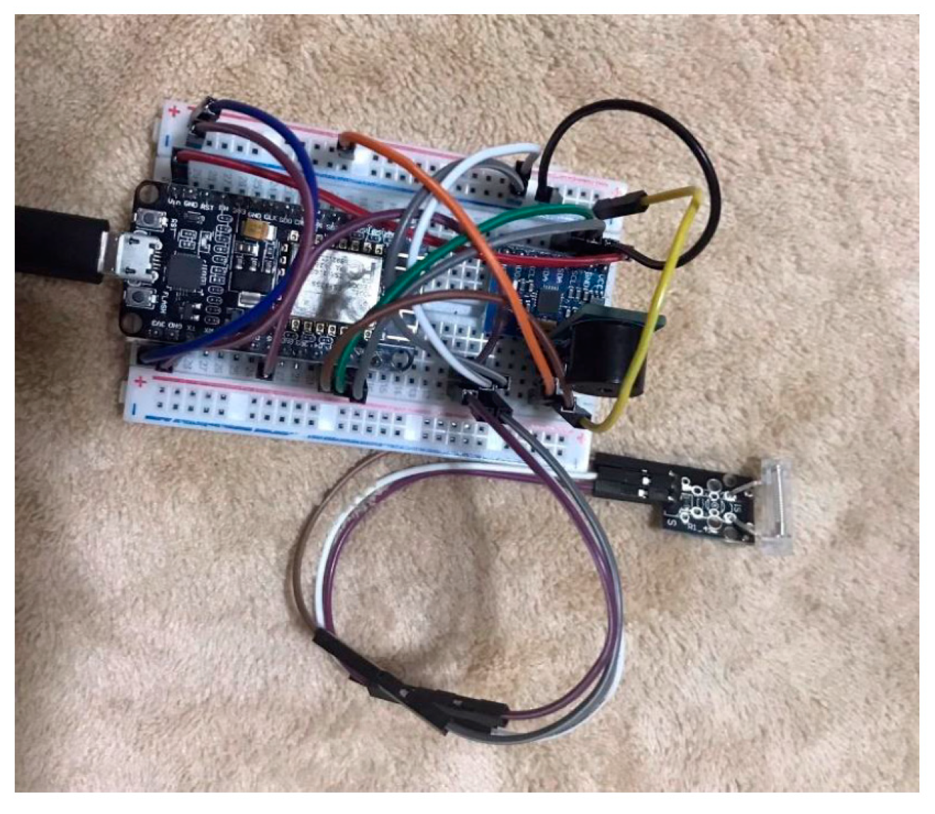
From Figure 1, it can be concluded that this research focuses on designing a device to assist patients with limited mobility in walking. This necessitates special vigilance to reduce the risk of close-proximity accidents. The proposed device is a foot-worn apparatus equipped with sensors to detect movement and inclination of objects, specifically the MPU6050 gyro sensor and KY-031 vibration sensor. These sensors are utilized to monitor the walking behavior of the wearer. In the event of abnormalities, the device activates a buzzer for auditory assistance and sends notifications to the caregiver via LINE Notify. The entire system is controlled and processed using the Node MCU ESP8266.
The research project at hand encompasses a comprehensive set of methodologies and procedural steps. These endeavors are outlined as follows:

3.1. Data Exploration and System Requirements

3.1.1. Software

  • Conduct a thorough examination of the Arduino Integrated Development Environment (IDE) software, which serves as the programming platform for Arduino. Delve into the essential command syntax relevant to variable declaration, sensor integration, and function invocation to enable seamless sensor operation. Additionally, explore the utilization of libraries to leverage pre-existing functions and variables.
  • Investigate the intricacies of transmitting messages via Line Notify using the NodeMCU ESP8266. This entails understanding the API-driven HTTP POST method to facilitate the delivery of textual content, stickers, or images to smartphones through the Line messaging application.

3.1.2. Hardware

  • Scrutinize the underlying principles governing the control board's functionality and the intricate workings of each individual sensor. This includes comprehending the interconnections between various pins, the permissible voltage ranges for both the board and sensors, and the configuration settings necessary for optimal sensor performance.
3.1.3. System Design (1) Employ vibration sensors to detect anomalies in the wearer's gait, enabling the identification of irregular walking patterns. (2) Employ inclination sensors to discern deviations in body posture and orientation during ambulation, thus capturing abnormal movements. (3) Incorporate an audible alert mechanism, such as a buzzer, to emit sound signals upon the detection of aberrant walking patterns. (4) Initialize the system by establishing a primordial connection to Wi-Fi signals, ensuring seamless internet connectivity. (5) Employ Line Notify to promptly notify caregivers or relevant personnel of any detected anomalies in the wearer's walking patterns.
This research proposes a fall detection method utilizing decision tree principles. The system starts by establishing a connection between the WiFi signal and the receiving system, with the initial acceleration serving as the input parameter. The system then initiates the fall detection process based on pre-defined program logic. The program is designed to examine the differences between lying down in various positions and falling in different orientations. If the detected activity corresponds to a normal lying down position, no alert will be triggered, as determined by a comparison of conditions based on predefined equations.
Falln= M /\ X /\ Y /\Z
When   n represents the pattern of falling,
/\ represents the logical conjunction "and," M represents the motion value from the Bluetooth accelerometer sensor, where
M = 1 indicates motion and M = 0 indicates no motion,
X represents the acceleration value along the x-axis from the WiFi accelerometer sensor,
Y represents the acceleration value along the y-axis from the WiFi accelerometer sensor,
Z represents the acceleration value along the z-axis from the WiFi accelerometer sensor.
If Falln is true according to Equation (1), such as falling forward, FallF represents falling to the front, FallR represents falling to the right, FallL represents falling to the left, and FallB represents falling to the back. Other possibilities may also exist. FallF to the left, FallF to the right, FallB to the left, and FallB to the right will store the falling data, trigger an alarm sound, and send a notification message indicating the falling event and the location of the fall to the emergency contact. After the occurrence of the fall event, if the person still feels movement three times, another notification will be sent indicating the ability to sense movement, whether in a lying (L) position or able to sit or stand (U). If no notification is sent after the fall event, it indicates that the fallen person is either unconscious or unable to sense their surroundings.
  • The structure and functioning of the system can be described as follows:
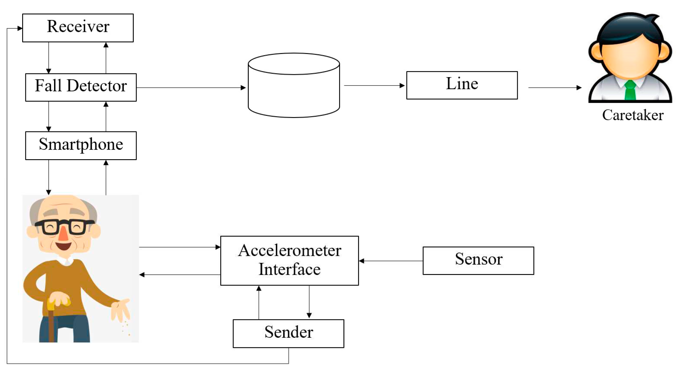
The researchers have designed the system structure as depicted in the diagram, which can be divided into two main parts:
Smartphone System (Android Operating System):
Receiver: The smartphone acts as a receiver and collects data from the Wi-Fi accelerometer sensor.
Fall Detector Process: The received data is processed by the fall detection algorithm to determine the type of fall. Once the fall type is identified, the system stores the fall data in an SQLite database, including the fall characteristics, date, time, and location coordinates.
Emergency Contact Notification: The system sends the fall characteristics and location information to the designated emergency contact. It also generates an alarm sound and displays the fall characteristics on the smartphone interface.
Wi-Fi Accelerometer Sensor:
Sensor Components: The Wi-Fi accelerometer sensor consists of sensors that measure acceleration along the X, Y, and Z axes.
Wi-Fi Accelerometer Interface: The sensor data is transmitted wirelessly via Wi-Fi to the smartphone using the Wi-Fi Accelerometer Interface.
The system works by collecting data from the Wi-Fi accelerometer sensor through the smartphone, processing it to detect fall events, and storing relevant information in a database. In case of a fall, the system notifies emergency contacts, provides an alarm, and displays the fall characteristics on the smartphone interface. The Wi-Fi accelerometer sensor component measures acceleration along different axes and communicates the data wirelessly to the smartphone via the Wi-Fi Accelerometer Interface.
Figure 2. Shows the structure of the system.
Preprints 79547 g002
The principle of decision trees, as applied in the context of a program aimed at capturing fall data and issuing assistance notifications through auditory and textual alerts on a smartphone, can be expounded upon with scholarly sophistication:
  • Initialization of the Decision Tree:
  • The program initiates the decision-making process by scrutinizing the occurrence of falls via data derived from the accelerometer sensor.
2.
Branching:
  • Crucial conditions or attributes, such as the tri-axial acceleration values (X, Y, and Z) obtained from the accelerometer sensor, are employed by the program to partition the data into distinct clusters based on fall characteristics.
3.
Decision-Making:
  • Each tier of the decision tree embodies a decision node predicated on the identified fall characteristics, encompassing forward, backward, leftward, or rightward falls.
4.
Termination of Decision-Making:
  • Upon reaching a juncture where further decisions are infeasible, the program proceeds to store the fall data, encompassing temporal, spatial, and contextual details regarding the fall incident.
  • Subsequently, the program disseminates a notification message, comprising comprehensive fall characteristics, geographical information, and auditory prompts, to the designated emergency contact via the smartphone interface.
The employment of the decision tree principle enables the program to effectively detect, analyze, and promptly respond to fall incidents, culminating in the provision of timely assistance through auditory and textual alerts on the smartphone platform.
3.1.4 Testing and System Refinement Conduct comprehensive testing to validate the system's functionality and ascertain its adherence to predefined requirements. Any detected anomalies or deviations from expected behavior should be promptly addressed through system refinements and iterative testing.

3.2. HARDWARE Development

3.2.1 The circuit configuration for the interconnection of the inclination sensor module (GY-521 MPU6050) with the NodeMCU board involves the establishment of specific electrical connections. The wiring arrangement is as follows:
  • The ground (GND) pin of the NodeMCU board is meticulously linked to the corresponding ground pin of the GY-521 module, ensuring a robust grounding connection.
  • The power supply voltage (VCC) pin of the NodeMCU board is judiciously connected to the designated voltage input pin of the GY-521 module, thereby providing a reliable power source.
  • Pin D1 of the NodeMCU board, which serves as the data transmission line for the serial clock (SCL) signal, is methodically linked to the corresponding SCL pin of the GY-521 module, facilitating synchronized data communication.
  • Likewise, pin D2 of the NodeMCU board, serving as the data transmission line for the serial data (SDA) signal, is meticulously connected to the respective SDA pin of the GY-521 module, enabling the exchange of data packets.
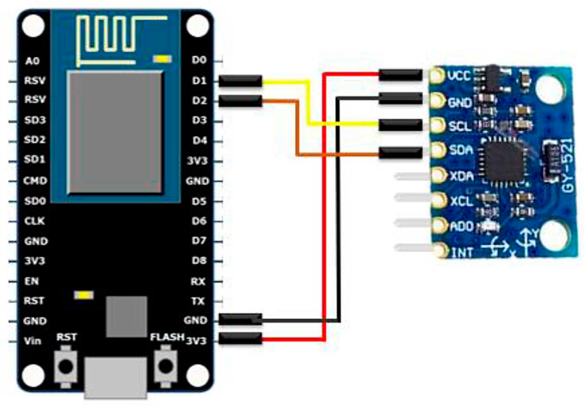
The careful establishment of these electrical connections allows for the seamless interaction between the NodeMCU board and the GY-521 MPU6050 inclination sensor module, enabling the acquisition of precise inclination measurements for various objects.
Figure 3. Connecting the sensor to measure the inclination of an object.
Preprints 79547 g003
The process of measuring the inclination of an object using an inclination sensor, such as the GY-521 MPU6050, can be elucidated as follows:
The GY-521 MPU6050 sensor facilitates the measurement of object inclination along the X-axis (Roll), Y-axis (Pitch), and Z-axis (Yaw). This pertains to quantifying the tilt or rotational movement of the object in different spatial axes within the three-dimensional coordinate system. The sensor, integrated within the MPU6050, comprises an accelerometer and a gyroscope, which operate in accordance with the following mathematical expressions:
  • Equations for determining the acceleration in the X, Y, and Z axes:
  • Acceleration_X = ax
  • Acceleration_Y = ay
  • Acceleration_Z = az
2.
Equation for calculating the overall acceleration:
  • Total_Acceleration = √(ax² + ay² + az²)
3.
Equations for assessing the inclination along the Roll (X) and Pitch (Y) axes:
  • Roll = atan2(ay, az)
  • Pitch = atan2(-ax, √(ay² + az²))
4.
Equations for evaluating the angular rates of rotation around the Roll (X), Pitch (Y), and Yaw (Z) axes:
  • Gyro_Rate_X = gx
  • Gyro_Rate_Y = gy
  • Gyro_Rate_Z = gz
These equations facilitate the computation of acceleration and angular rates of rotation in each specific axis. They serve the purpose of detecting object tilt or rotational motion and can be further utilized for control and system optimization endeavors.
3.2.2 The vibration sensor KY-031, also known as a shake switch or a shock sensor, is designed to detect and respond to physical vibrations or shocks. It consists of a spring-mounted contact switch that closes when subjected to a sufficient level of vibration or impact. When the sensor detects a vibration or shock, the spring inside it compresses or deforms, causing the contact switch to close momentarily. This closure of the switch creates an electrical connection between the two terminals of the sensor, indicating the presence of a vibration event. The operation of the KY-031 vibration sensor can be described using a simple threshold-based model. Let's assume that the sensor outputs a logical high voltage (1) when no vibration is present and a logical low voltage (0) when a vibration or shock is detected. The sensor can be connected to a microcontroller or any other digital input device. By monitoring the voltage level at the sensor's output pin, the microcontroller can determine whether a vibration event has occurred. The detection threshold of the KY-031 sensor can be adjusted using a potentiometer or a sensitivity control provided on the sensor. This allows users to customize the sensitivity of the sensor based on their specific requirements, the KY-031 vibration sensor detects vibrations or shocks by utilizing a spring-mounted contact switch. Its output signal can be used by a microcontroller or other digital devices to trigger appropriate actions or responses based on the detected vibrations. The wiring arrangement is as follows:
  • Connect the GND (Ground) pin of the NodeMCU to the GND pin of the KY-031 sensor. This establishes a common ground reference between the NodeMCU and the sensor.
  • Connect the VCC (Power) pin of the NodeMCU to the VCC pin of the KY-031 sensor. This supplies power to the sensor, ensuring proper functionality.
  • Connect pin D5 of the NodeMCU to the OUTPUT pin of the KY-031 sensor. This allows the NodeMCU to receive the output signal from the vibration sensor.
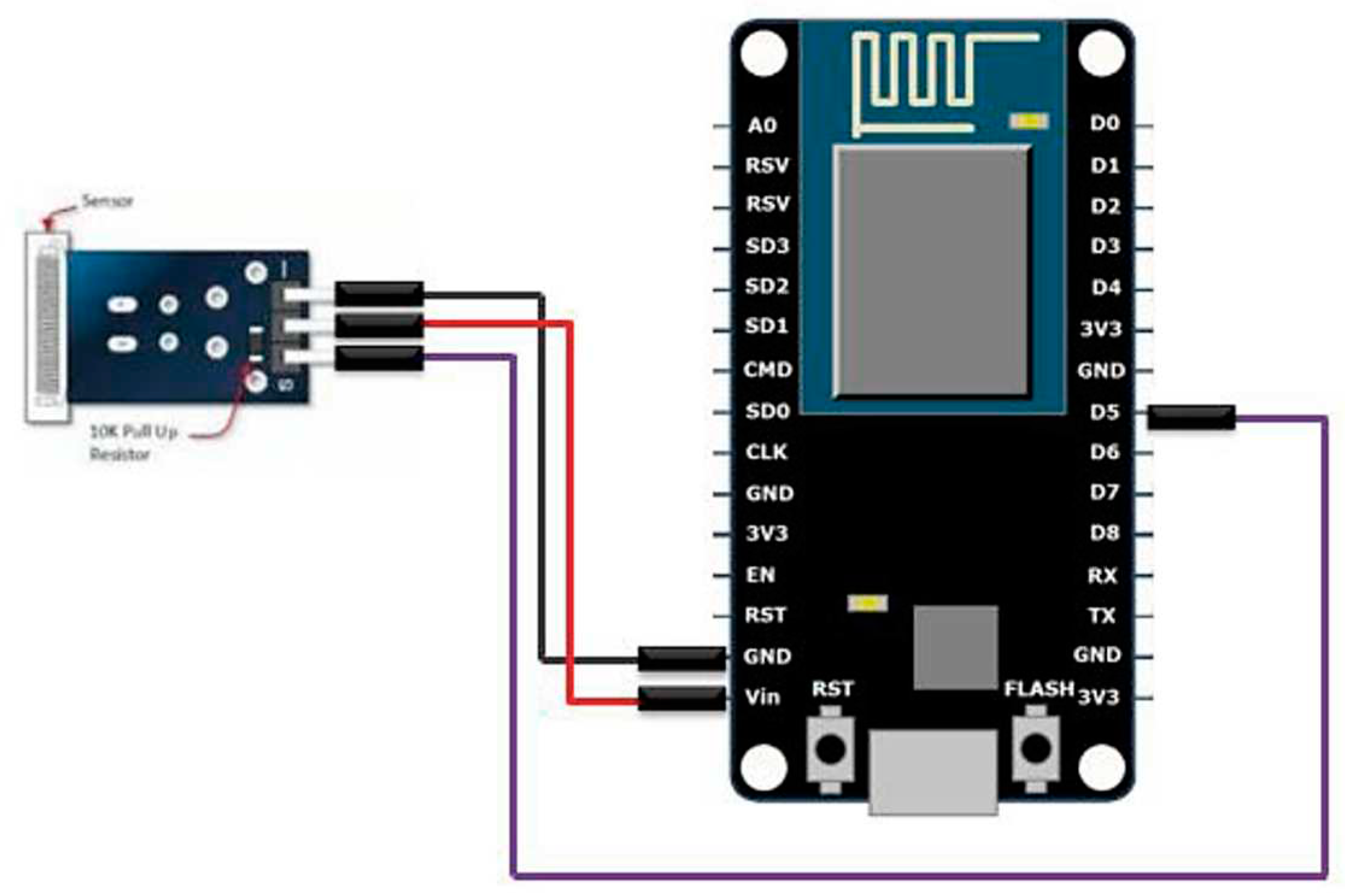
Figure 4. Connecting the vibration sensor.
Preprints 79547 g004
3.2.3 To connect the circuit for a sound alert sensor (buzzer sensor), you can follow these steps:
  • Connect the GND (Ground) pin of the NodeMCU to the GND pin of the buzzer sensor.
  • Connect the VCC (Voltage) pin of the NodeMCU to the VCC pin of the buzzer sensor.
  • Connect pin D3 of the NodeMCU to the OUTPUT pin of the buzzer sensor.
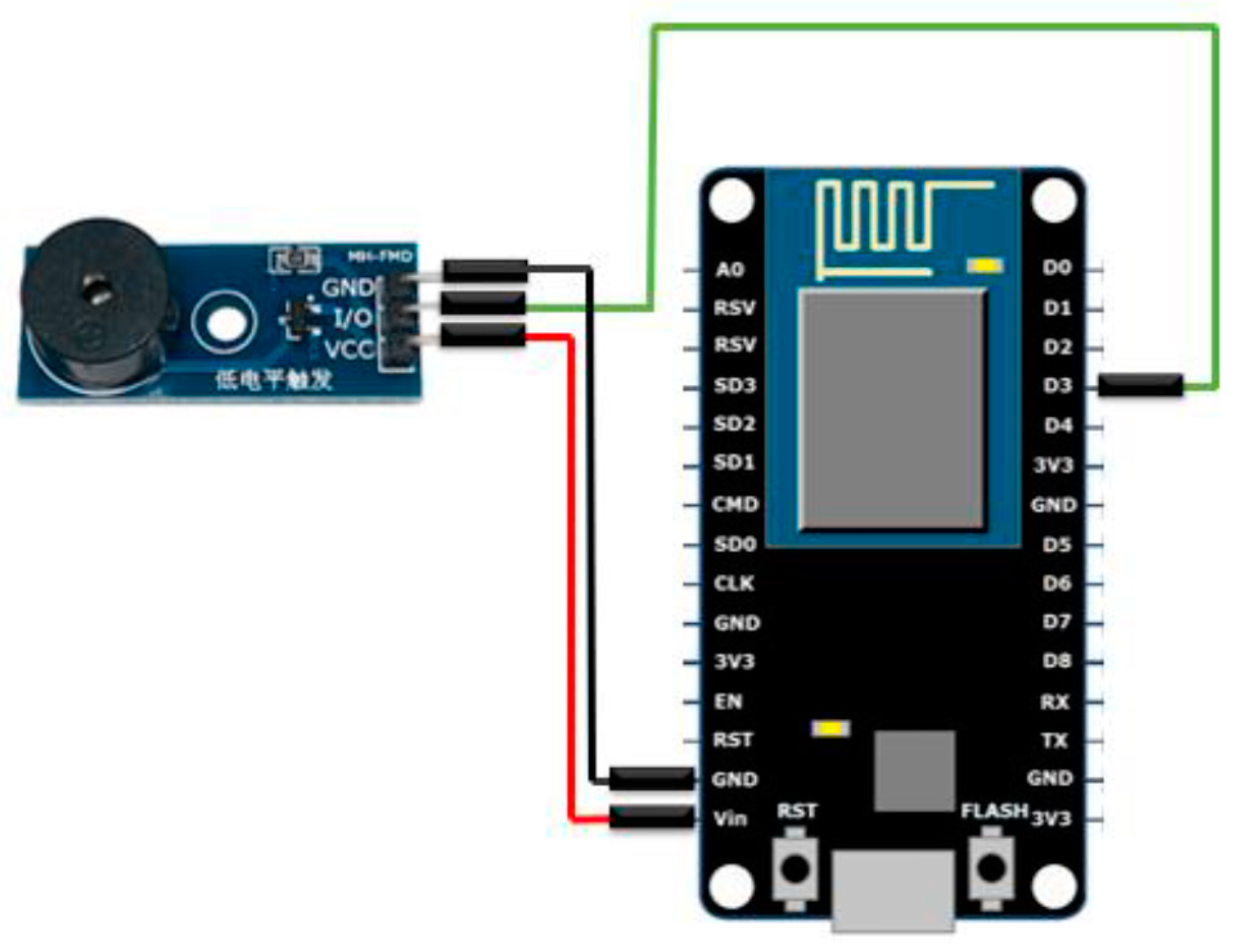
This configuration allows the NodeMCU to control the buzzer sensor. The GND and VCC connections provide power to the sensor, while pin D3 is used as an output to send signals to the buzzer sensor to produce sound alerts.
Figure 5. Sound Alert Sensor Connection.
Preprints 79547 g005
3.2.4 The devised system encompasses the following design elements:
  • The integration of a NodeMCU ESP8266 module enables seamless connectivity to a Wi-Fi network, thereby facilitating internet access for the device.
  • The system incorporates Line Notify, a robust messaging service, which is configured using a unique LINE TOKEN to establish a reliable communication channel.
  • Data acquisition is facilitated through the utilization of two sensors: the GY-521 MPU6050 sensor, responsible for capturing the inclination angle of the object under observation, and the KY-031 sensor, employed to detect and monitor vibrational patterns.
  • In the event of an abrupt impact occurrence, the system promptly captures relevant data from the GY-521 MPU6050 sensor to assess the situational parameters.
  • In the absence of any such impact, the system periodically retrieves data from the GY-521 MPU6050 sensor at regular intervals of 2 seconds to maintain a comprehensive monitoring approach.
  • A perceptible auditory alert is triggered by the system upon the detection of an object tilt, signifying a potential fall or hazardous event.
  • Furthermore, in instances where an object tilt is detected, the system consistently transmits notification messages via Line Notify at 10-second intervals, conveying critical information denoted by the phrase "The patient has encountered an accident."
  • Subsequent to the object regaining an upright position, indicative of the individual's ability to self-recover, the system ceases the auditory alert mechanism while simultaneously dispatching a notification message via Line Notify, elaborating on the individual's restored autonomy through the phrase "The patient is capable of self-assistance."
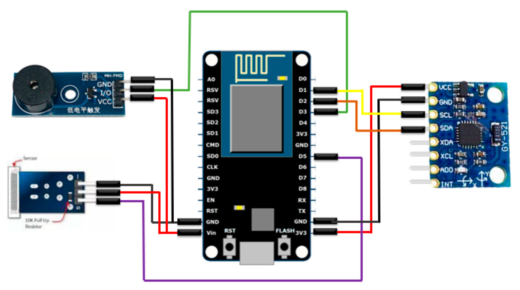
This carefully crafted design framework endeavors to provide an effective surveillance system, effectively identifying incidents such as falls or accidents, and promptly disseminating pertinent alerts through both audible cues and Line Notify messages. By prioritizing the safety and well-being of individuals, particularly patients necessitating support, this system contributes significantly to ensuring their enhanced security and overall welfare.
Figure 6. Shows the circuit connection of the fall alarm system.
Preprints 79547 g006
Figure 7. Shows the circuit connection of the fall alarm system.
Preprints 79547 g007

4. Results and Discussion

4.1.*Development of an Intelligent Ankle Device for Physiotherapy Patients. The objective of this study is to develop an intelligent ankle device that can effectively monitor and assess the movements, inclination, and vibrations experienced by patients during their physical rehabilitation sessions. The device, as depicted in Figure 8, is specifically designed to be worn by patients throughout their therapy sessions, enabling continuous monitoring of their physical condition. It incorporates state-of-the-art sensors, namely the GY-521 MPU6050 sensor for motion and inclination detection, as well as the KY-031 sensor for vibration detection. These sensors provide valuable data that is utilized to evaluate the patient's overall well-being and response to therapy. In the event of a fall, the intelligent ankle device is programmed to employ a multi-faceted alert system. Firstly, it leverages the LINE messaging application to send real-time notifications to designated healthcare providers or caregivers, enabling them to promptly attend to the patient's needs. This instantaneous communication channel ensures timely response and appropriate actions. Secondly, the device is equipped with an audible alert mechanism that emits a distinct sound upon detecting a fall. This auditory prompt serves as an additional means of drawing attention to the patient's condition, both for the patient themselves and those in close proximity. Furthermore, the intelligent ankle device continuously monitors the patient's movements, ensuring ongoing assessment and proactive measures. If a fall is detected, an immediate notification is transmitted via LINE, accompanied by a concise and informative message stating "The patient has experienced an accidental fall." This concise message aims to efficiently convey the urgency of the situation to the relevant individuals involved in the patient's care. In parallel, the audible alert system remains active, providing a continuous reminder to the patient that attention is required. This audible cue prompts the patient to assess their condition and seek assistance if necessary. Once the patient has successfully regained stability and can stand up unaided, the intelligent ankle device deactivates the audible alert and subsequently sends a notification through the LINE app, delivering the reassuring message "The patient has regained self-assistance capability." This notification serves as an acknowledgment that the patient has achieved a favorable state of self-sufficiency.

4.2. Evaluation of Intelligent Ankle Device Performance
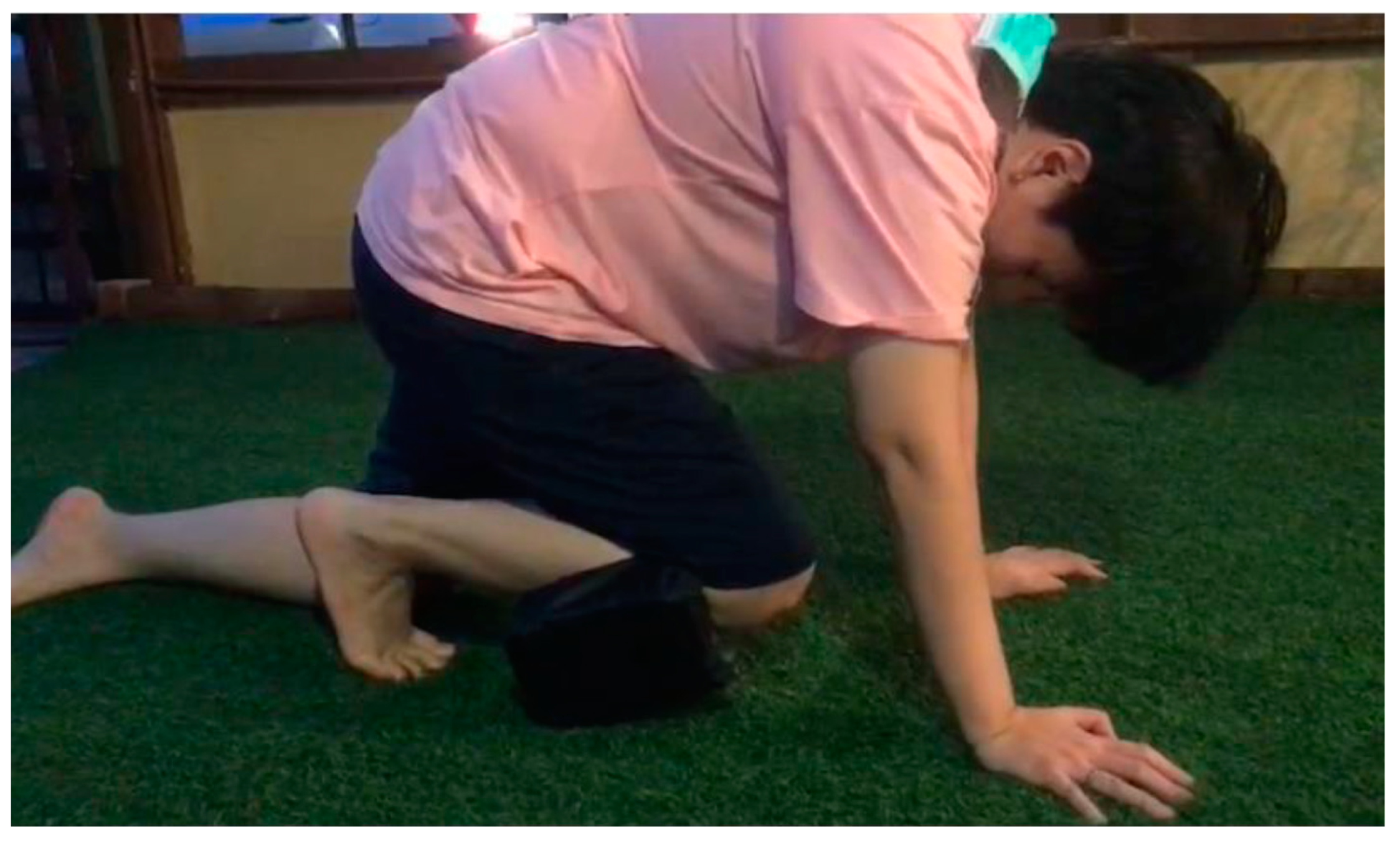
4.2.1 Motion and Vibration Detection Assessment The functionality of the motion and vibration detection component of the intelligent ankle device was subjected to thorough testing to ascertain its efficacy in accurately capturing user movements and detecting vibrations. The device's operational sequence is initiated upon the user's application of the device, thereby activating the motion detection functionality. Within the context of physical rehabilitation interventions, the potential for accidental falls necessitates a robust fall detection system. Consequently, during the testing phase, the device was programmed to promptly emit an audible alert within a specified timeframe of 2 seconds upon the detection of a fall event. However, once the user successfully regains an upright standing position unassisted, the device promptly ceases the alert mechanism.
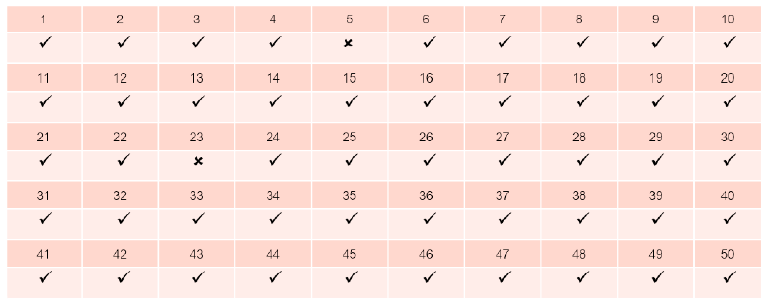
A comprehensive evaluation protocol encompassing a total of 50 fall simulation scenarios was meticulously executed to appraise the performance of the intelligent ankle device. Within this extensive dataset, two isolated instances exhibited unexpected behaviors, occurring specifically during walking activities. Rigorous scrutiny and subsequent investigation were conducted to identify and comprehend the root causes underpinning these infrequent anomalies.
Figure 9. In case the patient has an accident during physical therapy.
Preprints 79547 g009

4.2.2. Alert System Functionality

In the context of physical rehabilitation, it is crucial to incorporate an effective alert system within the intelligent ankle device to promptly notify relevant parties in case of unforeseen incidents. The alert system comprises two primary components: an audible alert mechanism and Line Notify messaging service for instant notifications. These components work in tandem to ensure timely dissemination of critical information to the appropriate stakeholders. When an accident occurs during the rehabilitation process, the intelligent ankle device triggers the alert mechanism, which initiates an audible sound to attract immediate attention. Simultaneously, the system activates the Line Notify messaging service to send an instant notification containing relevant details of the incident. The transmission of the Line Notify message occurs within a predetermined timeframe of 10 seconds, as illustrated in Figure 10. Furthermore, even if the patient manages to regain an independent standing position after a fall during the rehabilitation session, the system still initiates a Line Notify message within the same timeframe of 10 seconds. This notification serves as a confirmation to the caregivers that the patient has successfully self-recovered. The notification process is visually depicted in Figure 11. The integration of both audible alerts and Line Notify notifications within the intelligent ankle device facilitates seamless communication and prompt response between the device and the responsible healthcare providers. This enables swift interventions and appropriate support in the event of emergencies or accidents encountered during the rehabilitation process.
Figure 10. The performance test results of the prototype device can be alerted when there are 50 accidents.
Preprints 79547 g010
Figure 11. Notification in case the patient falls through the line.
Preprints 79547 g011
Figure 11. Notification in case the patient stands up.
Preprints 79547 g012
Upon the culmination of rigorous testing procedures conducted on the devised apparatus, it has manifested an exemplary level of efficacy, surpassing the threshold of 95% accuracy in its frontal obstruction detection capabilities. However, it is imperative to acknowledge the potential intricacies entailed in the identification of swiftly moving or diminutive entities, such as insects, which may impede the unimpeded functioning of the sensor system. Furthermore, it is crucial to underscore that intermittent discrepancies have been observed in the outcomes of distress signal transmissions, attributable to intermittent internet connectivity and suboptimal reception conditions encountered within select architectural frameworks. Nonetheless, it is noteworthy that the overall results remain within the acceptable parameters, thereby conferring upon the apparatus the successful completion of the rigorous testing phase and the fulfillment of its premeditated objectives.

5. Conclusions

The present research endeavors to devise a novel device aimed at assisting individuals with restricted mobility in their ambulation. A particular emphasis is placed on mitigating the perils associated with close-proximity mishaps. The proposed apparatus takes the form of a wearable contrivance affixed to the foot, equipped with a suite of sensors, notably the MPU6050 gyro sensor and KY-031 vibration sensor. These sensors serve the purpose of monitoring the gait patterns and angular displacements of the user. In the event of any aberrations, the device promptly activates an auditory alert system via a buzzer and simultaneously dispatches notifications to the designated caregiver through the employment of LINE Notify. The holistic operational control and data processing of the entire system is entrusted to the Node MCU ESP8266. The principal objective of this study is to engineer and architect an Internet of Things (IoT) system tailored to cater to the exigencies of the medical domain. The researchers have successfully devised a prototype exemplifying a sophisticated ankle device that aptly discerns incidents of falls and instantaneously relays informative messages to the user's smartphone. To gauge the efficacy of the notification system, rigorous evaluations were conducted employing the Line Notify application. The findings manifest a commendable success rate of 48 out of 50 instances in detecting falls, albeit accompanied by two instances of false alarms occurring during routine ambulation. As an aggregate measure, the smart ankle device showcases a commendable operational efficiency of 98%. However, it is imperative to underscore that this research is still at the prototypical stage, necessitating further scholarly investigations and developments, including synergistic collaborations with physiotherapists and healthcare professionals. These endeavors are indispensable to ensure optimal performance benchmarks and cater to the divergent requirements of end-users. This research endeavors to develop and evaluate a sophisticated ankle device boasting fall detection capabilities, underpinned by IoT technology. While the outcomes underscore the effectiveness of the fall detection mechanism, the occurrence of sporadic false alarms necessitates further refinements and cooperative engagements with domain experts to enhance the device's functionality and ascertain its commercial viability. Notably, the research significantly underscores the salience of Internet connectivity, warranting comprehensive deliberations on fortifying the underlying infrastructure. The envisioned smart ankle device holds promising potential for multifarious applications encompassing fall alert systems, amelioration of durability factors, and commercialization prospects. In light of this, responsive IoT systems emerge as a sine qua non and assume paramount significance in this research undertaking. Thus, future investigations should be geared towards comprehensively exploring and developing supplementary features in close collaboration with physiotherapists and healthcare professionals, thereby maximizing the attainable outcomes and aligning with the specific needs of the target user base. The proposed system encapsulates manifold benefits with respect to fall detection and safety alert applications, mandating concerted efforts to augment its longevity, robustness, and resilience for enduring usage scenarios. Moreover, a rigorous exploration of its commercialization prospects is warranted to facilitate its tangible deployment in real-world contexts.

References

  1. Friedl, K.E.; Looney, D.P. With life there is motion. Activity biomarkers signal important health and performance outcomes. J. Sci. Med. Sport 2023, in press.
  2. Fritz, S.; Lusardi, M. White paper: “Walking speed: The sixth vital sign”. J. Geriatr. Phys. Ther. 2009, 32, 2–5. [Google Scholar] [CrossRef]
  3. Atrsaei, A.; Corrà, M.F.; Dadashi, F.; Vila-Chã, N.; Maia, L.; Mariani, B.; Maetzler, W.; Aminian, K. Gait speed in clinical and daily living assessments in Parkinson’s disease patients: Performance versus capacity. NPJ Park. Dis. 2021, 7, 24. [Google Scholar] [CrossRef]
  4. Merchant, R.A.; Goh, J.; Chan, Y.; Lim, J.; Vellas, B. Slow gait, subjective cognitive decline and motoric cognitive RISK syndrome: Prevalence and associated factors in community dwelling older adults. J. Nutr. Health Aging 2021, 25, 48–56. [Google Scholar] [CrossRef]
  5. Ozsoy, I.; Kodak, M.I.; Zerman, N.; Karartı, C.; Ozsoy, G.; Erturk, A. Gait speed predictors and gait-speed cut-off score to discriminate asthma control status and physical activity in patients with asthma. Adv. Respir. Med. 2022, 90, 164–170. [Google Scholar] [CrossRef] [PubMed]
  6. Montero-Odasso, M.; Pieruccini-Faria, F.; Bartha, R.; Black, S.E.; Finger, E.; Freedman, M.; Greenberg, B.; Grimes, D.A.; Hegele, R.A.; Hudson, C. Motor phenotype in neurodegenerative disorders: Gait and balance platform study design protocol for the Ontario neurodegenerative research initiative (ONDRI). J. Alzheimer’s Dis. 2017, 59, 707–721. [Google Scholar] [CrossRef] [PubMed]
  7. Ezzati, A.; Katz, M.J.; Lipton, M.L.; Lipton, R.B.; Verghese, J. The association of brain structure with gait velocity in older adults: A quantitative volumetric analysis of brain MRI. Neuroradiology 2015, 57, 851–861. [Google Scholar] [CrossRef]
  8. Braak, H.; Braak, E. Staging of Alzheimer’s disease-related neurofibrillary changes. Neurobiol. Aging 1995, 16, 271–278. [Google Scholar] [CrossRef] [PubMed]
  9. Jia Luen Chua, Yoong Choon Chang, and Wee Keong Lim, “Intelligent Visual Based Fall Detection Technique for Home Surveillance”, Computer, Consumer and Control (IS3C) 2012, pp. 183 – 187.
  10. Miao Yu, Adel Rhuma, Syed Mohsen Naqvi, Liang Wang and Jonathon Chambers, “Posture Recognition Based Fall Detection System For Monitoring An Elderly Person In A Smart Home Environment”, Information Technology in Biomedicine, IEEE Transactions on Issue: 99, 2012, pp. 1– 11.
  11. Damien Brulin, Yannick Benezeth, and Estelle Courtial, “Posture Recognition Based on Fuzzy Logic for Home Monitoring of the Elderly”, Information Technology in Biomedicine, IEEE Transactions Volume: 16, Issue: 5, 2012, pp. 974 – 982.
  12. Caroline Rougier, Edouard Auvinet, Jacqueline Rousseau, Max Mignotte and Jean Meunier, “Fall Detection from Depth Map Video Sequences”, 9th International Conference on Smart Homes and Health Telematics (ICOST), 2011, pp. 121 – 128.
  13. Shaou-Gang Miaou, Pei-Hsu Sung, and Chia-Yuan Huang, “A Customized Human Fall Detection System Using Omni-Camera Images and Personal Information”,IEEE International Conference on Distributed Diagnosis and Home Healthcare (D2H2) Conference, 2006, pp.103-107.
  14. Peng Shen Ong, et al, “An FPGA-Based Hardware Implementation of Visual based Fall Detection,” IEEE International Conference on Region 10 Symposium, 2014, pp. 397-402.
  15. Behçet Uğur Töreyin, Yiğithan Dedeoğlu and A. Enis Çetin, “HMM based falling person detection using both audio and video”, IEEE International Workshop on Human–Computer Interaction,Vol. 3766, 2005, pp. 211–220.
  16. Alex Edgcomb and Frank Vahid, “Automated Fall Detection on PrivacyEnhanced Video”, IEEE International Conference on Engineering in Medicine and Biology Society (EMBC), 2012, pp. 252-255.
  17. Ji Tao, et al, “Fall Incidents Detection for Intelligent Video Surveillance,” IEEE International Conference on Information, Communications and Signal Processing, 2005, pp. 1590 - 1594.
  18. Georgios Mastorakis and Dimitrios Makris, “Fall detection system using Kinect’s infrared sensor”, Journal of Real-Time Image Processing, Vol. 9, Issue 4, 2012, pp. 635-646.
  19. Vitoantonio Bevilacqua, et al, “Fall Detection in indoor environment with Kinect sensor,” IEEE International Symposium on Innovations in Intelligent Systems and Applications (INISTA), 2014, pp. 319-324.
  20. Y.S. Delahoz and M.A. Labrador, “Survey on fall detection and fall prevention using wearable and external sensors,” Sensors, vol. 14, no. 10, pp. 19806–19842, 2014.
  21. S. Eamsamai, R. Mhuansit and C. Thongmag, “An elderly care model among caregiving volunteers at Phukrang municipality, Amphur Praputthabat, Saraburi province,” (In Thai). Nursing Journal of the Ministry of Public Health, vol. 22, no. 3, pp. 77-87, 2012.
  22. T. Yu, A. Stamm and R. Hartanto, “Design and implementation of a Bluetooth low energy-based local area network for fall detection,” in Proc. 12th Conference of the International Sports Engineering Association, Queensland, Australia, March 26-29, 2018.
  23. Y. Lee, H. Yeh, K. Kim and O. Choi, “A real-time fall detection system based on the acceleration sensor of smartphone,” International Journal of Engineering Business Management, vol. 10, pp. 1–8, 2018.
  24. C. Ko, F. Leu and I. Lin, “A wandering path tracking and fall detection system for people with dementia,” in Proc. 9th International Conference on Broadband and Wireless Computing, Communication and Applications, Guangdong, China, November 8-10, 2014.
  25. Y. Xiang, Y. Tang, B. Ma, H. Yan, J. Jiang and X. Tia, “Remote safety monitoring for elderly persons based on omni-vision analysis,” PLoS ONE, vol. 10, no. 5, e0124068, 2015.
  26. L.H. Juang and M.N. Wu, “Fall down detection under smart home system,” Journal of Medical Systems, vol. 39, no. 10, pp. 1–12, 2015.
  27. W. Zhuang, X. Sun, Y Zhi, Y. Han and H. Mao. “A novel wearable smart button system for fall detection,” in Proc. the 1st International Conference on Materials Science, Energy Technology, Power Engineering (MEP 2017), Hangzhou, China, April 15-16, 2017, pp. 020075-1 - 020075-6.
  28. V. Muenruekam, V. Sudkratok, S. Surarochprajak and T. Thongkrau, “Automatic accident alert system using multi-layer perceptron,” (In Thai). TNI Journal of Engineering and Technology, vol. 5, no. 2, pp. 49 – 53, 2017.
  29. Caya, M. V. C., Magwili, G. V., Agulto, D. L., Laranang, R. J., & Palomo, L. K. G. (2019). Supervised machine learning-based fall detection. 2018 IEEE 10th International Conference on Humanoid, Nanotechnology, Information Technology, Communication and Control, Environment and Management, HNICEM 2018, 1–6. [CrossRef]
  30. He, J., Zhou, M., Wang, X., & Han, Y. (2016). A wearable method for autonomous fall detection based on Kalman filter and k-NN algorithm. Proceedings - 2016 IEEE Biomedical Circuits and Systems Conference, BioCAS2016, 420–423. [CrossRef]
  31. Hsu, Y. W., Chen, K. H., Yang, J. J., & Jaw, F. S. (2017). Smartphone-based fall detection algorithm using feature extraction. Proceedings - 2016 9th International Congress on Image and Signal Processing, BioMedical Engineering and Informatics, CISP-BMEI 2016, 1535–1540. [CrossRef]
  32. Ning, Y., Hu, S., Nie, X., Liang, S., Li, H., & Zhao, G. (2018). Real-time Action Recognition and Fall Detection Based on Smartphone. Proceedings of the Annual International Conference of the IEEE Engineering in Medicine and Biology Society, EMBS, 2018, 4418–4422. [CrossRef]
  33. ShahzadShahzad, A., & Kim, K. (2019). FallDroid: An Automated Smart-Phone-Based Fall Detection System Using Multiple Kernel Learning. IEEE Transactions on Industrial Informatics, 15(1), 35–44. [CrossRef]
  34. Sucerquia, A., López, J. D., & Vargas-Bonilla, J. F. (2017). SisFall: A fall and movement dataset. Sensors (Switzerland), 17(1). [CrossRef]
  35. Tsinganos, P. & Skodras, A. (2018). On the comparison of wearable sensor data fusion to a single sensor machine learning technique in fall detection. Sensors, 18(2), 59-67. [CrossRef]
  36. Ricardo Goncalves1,2,Joao Reis1, Emanuel Santana1, Nuno B. Carvalho1,2,Pedro Pinho1,3 and Luca Roselli4, “Smart Floor: Indoor navigation based on RFID”, In Proc. IEEE JOURNAL 2013,103- 106.
  37. Lih-Jen Kau, et al., “A Smart Phone-Based Pocket Fall Accident Detection, Positioning, and Rescue System”, In Proc. IEEE JOURNAL OF BIOMEDICAL AND HEALTH INFORMATICS, JANUARY 2015.
  38. Ludovic Minvielle, et al., “Fall Detection Using Smart Floor Sensor and Supervised Learning*”, In Proc. International Conference of the IEEE 2017, 3445-3448.
  39. Ben Heller, Terry Senior and Jon Wheat. “Smart Floor with Integrated Triboelectric Nanogenerator As Energy Harvester and Motion Sensor”, In Proc. American Chemical Society United Kingdom, 2017, 26126-26133. [CrossRef]
  40. Amman, Jordan Leicester, “Indoor Human Detection and Tracking Using Advanced Smart floor”, In Proc. International Conference on Information and Communication Systems (ICICS),2017,34- 39.
  41. Angel Ramos และ Antonio Lazaro, “Time-domain UWB RFID tags for smart floor applications” In Proc. IEEE journal of RFID Technology and applications Conference, 2014,165-169.
  42. Apkan, V., Agbogun J., Omotehinwa, O., & Omotehinwa, O. T. (2019). Development of an Automatic Body Mass Index Machines. P. 42-51. In: Proceedings of the 1st Ibadan Conference on Biomedical Engineering ICBME 1, 5-8 February, Ibadan, Nigeria.
  43. Godfrey, A. Wearables for independent living in older adults: Gait and falls. Maturitas 2017, 100, 16–26. [Google Scholar] [CrossRef] [PubMed]
  44. Strozzi, N.; Parisi, F.; Ferrari, G. Impact of on-body IMU placement on inertial navigation. IET Wirel. Sens. Syst. 2017, 8, 3–9. [Google Scholar] [CrossRef]
  45. Garai, Á.; Péntek, I.; Adamkó, A. Revolutionizing healthcare with IoT and cognitive, cloud-based telemedicine. Acta Polytech. Hung 2019, 16, 163–181. [Google Scholar]
  46. Abdellatif, M.M.; Mohamed, W. Telemedicine: An IoT Based Remote Healthcare System. Int. J. Online Biomed. Eng. 2020, 16.
  47. Nguyen, H.H.; Mirza, F.; Naeem, M.A.; Nguyen, M. A review on IoT healthcare monitoring applications and a vision for transforming sensor data into real-time clinical feedback. In Proceedings of the 2017 IEEE 21st International Conference on Computer Supported Cooperative Work in Design (CSCWD), Wellington, New Zealand, 26–28 April 2017; pp. 257–262. [Google Scholar]
  48. Barata, J.J.R.; Munoz, R.; Silva, R.D.D.C.; Rodrigues, J.J.; De Albuquerque, V.H.C. Internet of Things based on electronic and mobile health systems for blood glucose continuous monitoring and management. IEEE Access 2019, 7, 175116–175125. [Google Scholar] [CrossRef]
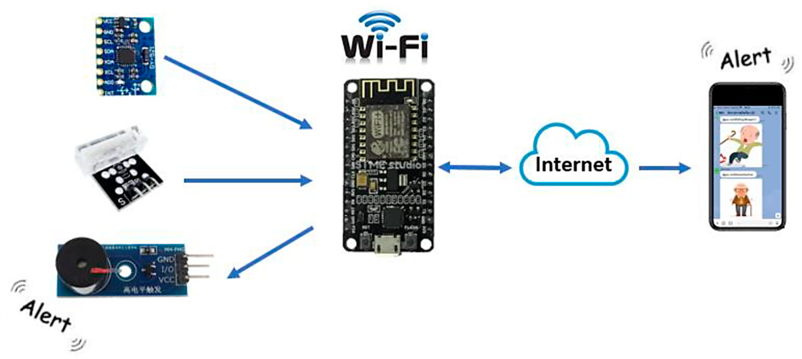
Figure 1. Conceptual Framework.
Preprints 79547 g001
Figure 8. Inserting the smart ankle device during physical exercise.
Preprints 79547 g008
Disclaimer/Publisher’s Note: The statements, opinions and data contained in all publications are solely those of the individual author(s) and contributor(s) and not of MDPI and/or the editor(s). MDPI and/or the editor(s) disclaim responsibility for any injury to people or property resulting from any ideas, methods, instructions or products referred to in the content.
Copyright: This open access article is published under a Creative Commons CC BY 4.0 license, which permit the free download, distribution, and reuse, provided that the author and preprint are cited in any reuse.
Prerpints.org logo

Preprints.org is a free preprint server supported by MDPI in Basel, Switzerland.

Subscribe

© 2024 MDPI (Basel, Switzerland) unless otherwise stated