1. Introduction
This work is a feature that was added to an existing education robotics software tool. The tool is presented in [
1,
2,
3,
4]. The work presented only adds the integration of a physical arm to motivate the students to complete their assignments. The tool simulates a virtual arm that can be set up to model an arm’s dynamics that the students can use to develop and test their programs. This virtual arm allows the students to move the arm by programming the movements of each of its joint motors. In this activity, called Joint Programming and described in [
3], the students move the arm along a specified trajectory by directly controlling the instantaneous velocity of each or the arm’s joint motors. Differential movements, described in [
4], is a type of joint programming where the arm is moved with a specified constant velocity along a specified path. It is used in painting, welding and application requiring precise velocities. Both of these types of movements require the consideration of the arm’s dynamic behaviors. For example, a heavier arm must take more time to accelerate and must begin to reduce its velocity earlier in the path to avoid overshooting the target.
The educational software tool has been designed to allow users to input the specifications of the robotic arm, including its dynamic properties. The user can provide the Denavit and Hartenberg (DH) parameters for each link to specify the arm's kinematic characteristics. The same input interface allows the user to input the maximum acceleration for each joint motor in both increasing and decreasing velocity scenarios, as well as the maximum speed. These values define the quickest rate at which a joint motor can alter its velocity and its highest attainable speed.
Currently, the virtual arm is represented using a stick figure format because it must adapt to various kinematic configurations, as defined by the user-provided DH parameters. However, the graphical representation of the virtual arm could stand to benefit from enhancements.
Joint programming is a technique used to maneuver a robotic arm along a predetermined path, with the goal of positioning its end-effector to a specific location and orientation while avoiding obstacles. This programming task entails calculating velocity polynomials for each joint motor such that the collective set of polynomials governs the arm's trajectory. If a joint motor is unable to adhere to its prescribed velocity schedule, the end-effector's velocity and trajectory will be altered, potentially putting the arm at risk of colliding with obstacles. Thus, it is essential that the velocity schedule for each joint motor is achievable. Failing to consider, or inadequately accounting for, the robotic arm's dynamics can lead to unattainable velocity schedules. For instance, a joint of the arm might not be able to accelerate as rapidly as the schedule demands.
Each velocity polynomial is computed by solving a set of simultaneous equations to determine all the polynomial's unknowns. These equations are formulated based on constraints such as the initial and final angle and velocity the joint should have, along with a maximum acceleration limit. The number of constraints determines the order of the polynomial. A common approach involves using blended polynomials that have an acceleration period, a cruising period, and a deceleration period, much akin to driving a car. Each blend is a separate polynomial that needs to be computed. If the arm's dynamics are not considered, the blends may be overlooked, simplifying the problem to a trivial state. For example, consider driving a car a distance of 2 miles in exactly 2 minutes. One cannot simply travel at one mile per minute (60 MPH) because the time taken by the car to accelerate to cruising speed and the time needed to decelerate to a stop must be factored in. Therefore, the car must actually cruise at a higher speed to compensate. However, if one disregards dynamics and assumes the car can instantaneously accelerate from 0 to 60 MPH, the problem becomes trivial: just cruise at 60 MPH.
Small toy robotic arms, while cost-effective and generally work well, are lightweight and thus exhibit minimal dynamic behaviors. Their rapid acceleration capabilities mean that their dynamics can often be overlooked while still achieving a satisfactory trajectory. However, this can present a problem if a student, trained in joint programming using a small toy arm, then attempts to program an industrial arm; their methods might not be applicable. The ideal solution is to make the small toy arm emulate the behavior of a large, heavy industrial arm, thereby necessitating proper consideration of dynamics to successfully maneuver the arm.
This paper presents a solution involving the integration of a small physical arm, namely the DOBOT, with an educational tool, to provide the experience of programming a heavy industrial arm. The tool was also integrated with an arm that utilizes Hitec servo motors, [
5], commonly used in small educational arms or robotic kits.
1.1. Literature Review
The work presented in this paper presents the integration of a physical but small robotic arm to our existing robotics educational tool that uses a virtual robotic arm. The existing tool is designed to support teaching and learning concepts that are typically found in introductory robotics courses. The textbook titled “Introduction to Robotics,” [
6] was used as a guide in the development of this tool. The tool supports topics including the DH parameter and frame placement convention, forward and inverse kinematics, trajectory planning and differential movements, both part of a general topic of joint programming, and robotic vision. The tool offers the flexibility to model any robotic arm that can be specified by its DH parameters. The virtual arm is created by entering its DH parameters, its range of movement, the types of joints either prismatic or revolute and the limits on acceleration. The limits on acceleration is used to model the dynamics of the arm.
The purpose of this tool is to offer a way for students to learn the course material without the need for a large and expensive physical robotic arm, see [
1,
2,
7]. It gives the student a learning support platform that relies on modeling and simulating a virtual robotic arm or a small toy arm with the addition presented in this paper.
Introduction to Robotics is a course designed to give the student the fundamental knowledge of robotics. This knowledge is needed to advance robotics education further and includes low level control of the joint motors of the arm. There are many robotic simulators such as [
8,
9,
10,
11,
12] that are both commercial and free. These can be used for educational purposes however their arms are controlled through higher level commands that do not lend themselves to joint programming. Our tool is specifically designed for this introductory robotics course and the activities that it can support are aligned with the course’s textbook.
There are software tools that support the integration of physical arms however they are generally focused on K-12 and do not support learning advanced concepts. In [
13] they present the IRobotQ3D robot simulator where student use the Lego Mindstorms kits to build the robot first then program the steps that will make it move. In [
14] they present a tool that uses a physical and virtual robot combination. However, the design of the arm is not by its DH parameters but rather by adding wheels and other physical parts and the programming is not at the joint motor level but higher. Their tool is aimed at the K-12 group. In [
15,
16] they use small inexpensive educational robots but their implementation is also aimed at K-12 and does not allow for joint level programming. In [
17] they present a small robotic arm that can be controlled remotely via a web server however it also does not allow for joint level programming. In addition, a reliable and high-speed internet connection must be available to the students.
There are also tools aimed at higher education but they are generally not considered to be a full integrated development environment (IDE) as is the tool describes in this paper. In [
18] they focus on the DH parameters and robot kinematics. It allows the student to specify the DH parameters and the web-based application draws the corresponding arm. This tool does not support joint programming. In [
19] they developed a MATLAB Tool box for Robotics made freely available. This library is popular but is not an IDE. It requires the student to write programs in MATLAB. The library supports the implementation of a virtual arm but the students need to link the virtual arm into their program. While this tool is well suited for students pursuing an education in a robotics discipline, it is not well suited for a student taking a simple intro to robotics course as an elective. The learning curve to learn MATLAB and implement their virtual arm is much higher than what is needed for the presented tool. This tool like others also perform much of the work that the students should be implementing instead. For example, Corke’s tool has functions to compute a trajectory whereas in the presented tool the student must implement a program to compute the trajectory.
Small light weight arms are also commonly used although they tend to be used in K-12 settings. In [
20] they present one such implementation that uses standard LEGO Mindstorm Kits.
Large physical arms are not designed for educational purposes and generally come with a controller that performs all of the joint programming. They generally do not allow the student to bypass the controller to gain direct access to the joint motors due to liability and safety reasons. However, one industrial arm does allow for joint programming, the Franka Emika robot [
21] the controller does not perform the joint programming but does supervise the movements to assure safety. While this may seam like the perfect solution, being a large industrial arm, it comes with a high initial and maintenance cost, requires dedicated lab space, and poses dangers to humans who get in the way of the arm. Furthermore, while they support trajectory planning, they do not support differential movements which is also part of joint programming. To be useful in education, differential movements must leave evidence of correct movement that cannot be observed by simply looking at the movement. For example, the presented tool can paint on a virtual canvas and leave evidence of correct movement by looking at the resulting painted canvas. This can be performed while a physical arm is tracking the movements of the virtual arm. The canvas will still be virtual.
2. Materials and Methods
We choose the DOBOT robotic arm, [
22], for this application since its small and inexpensive yet it’s of high quality having good accuracy, repeatability, durability, and reliability. Our educational software tool however can integrate with many small robotic arms. Some customization may require some new code to be added to the software tool as was the case using the DOBOT.
The solution is to simply have the physical arm track the movements of the virtual arm. The simulation engine that models the virtual arm runs in a cycle. In each cycle the virtual arm sends messages to the physical arm updating its current location. Depending on the arm and its controller, the location update may consist of a set of updated joint angles or an updated location for the end-effector.
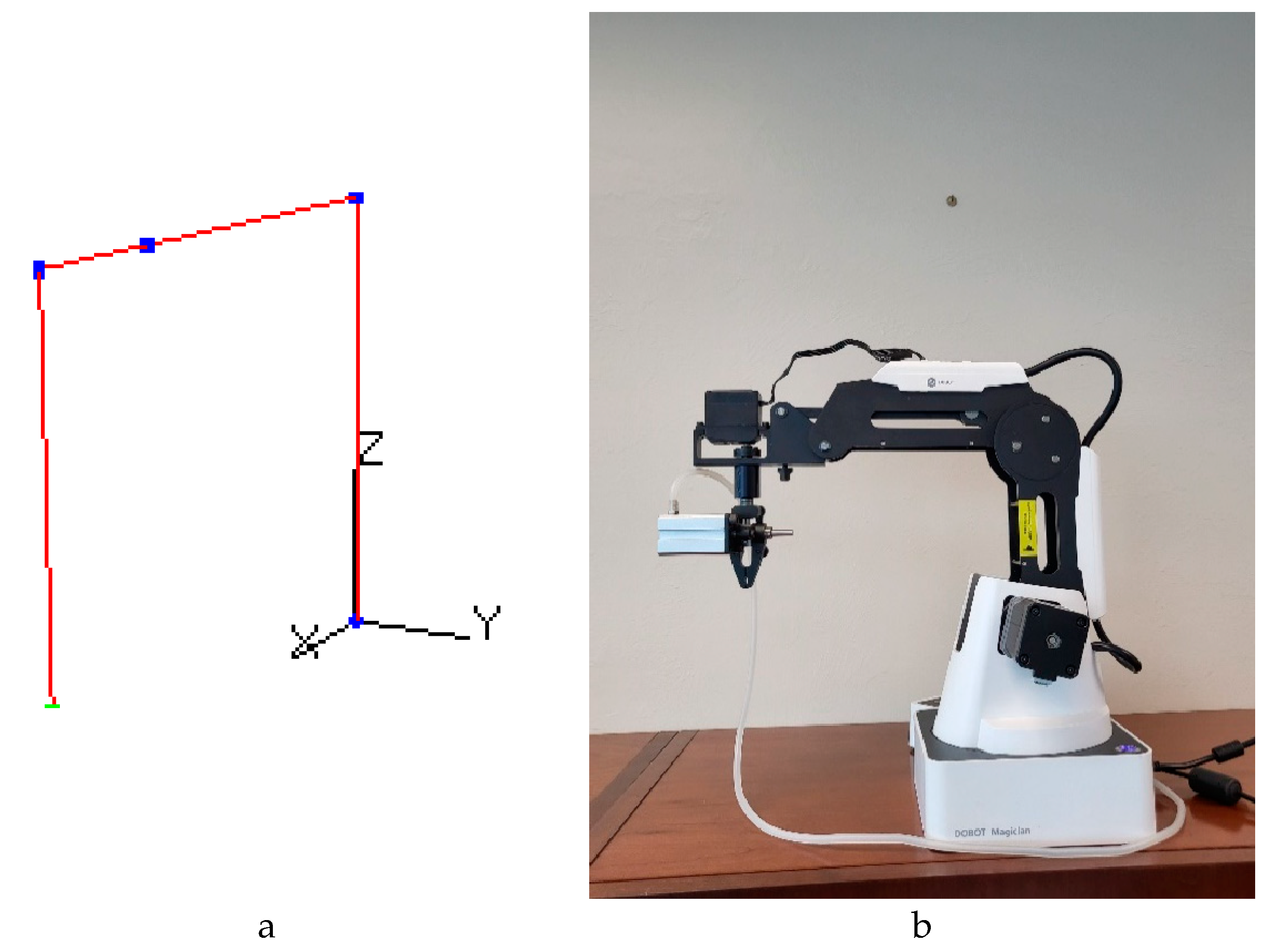
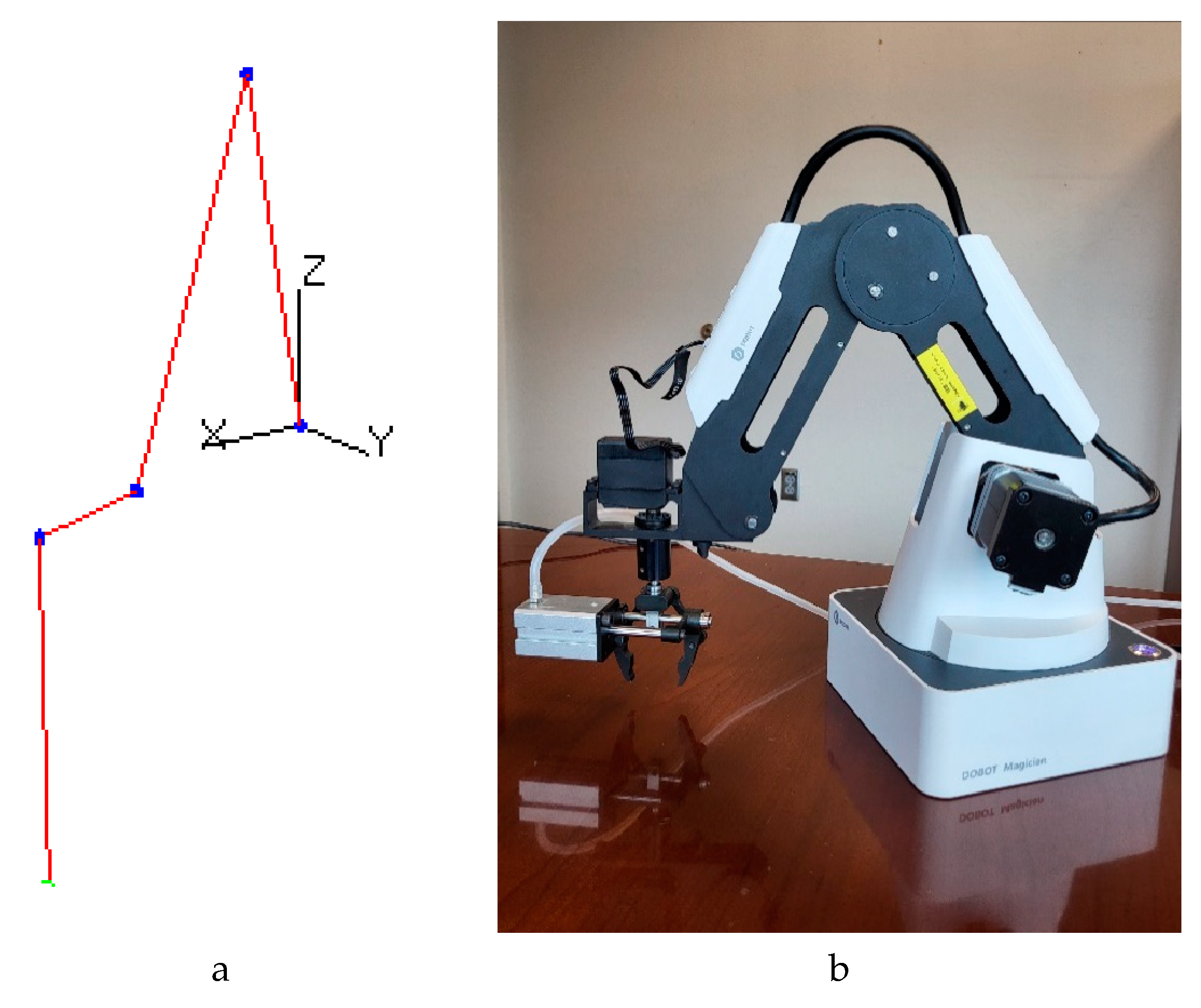
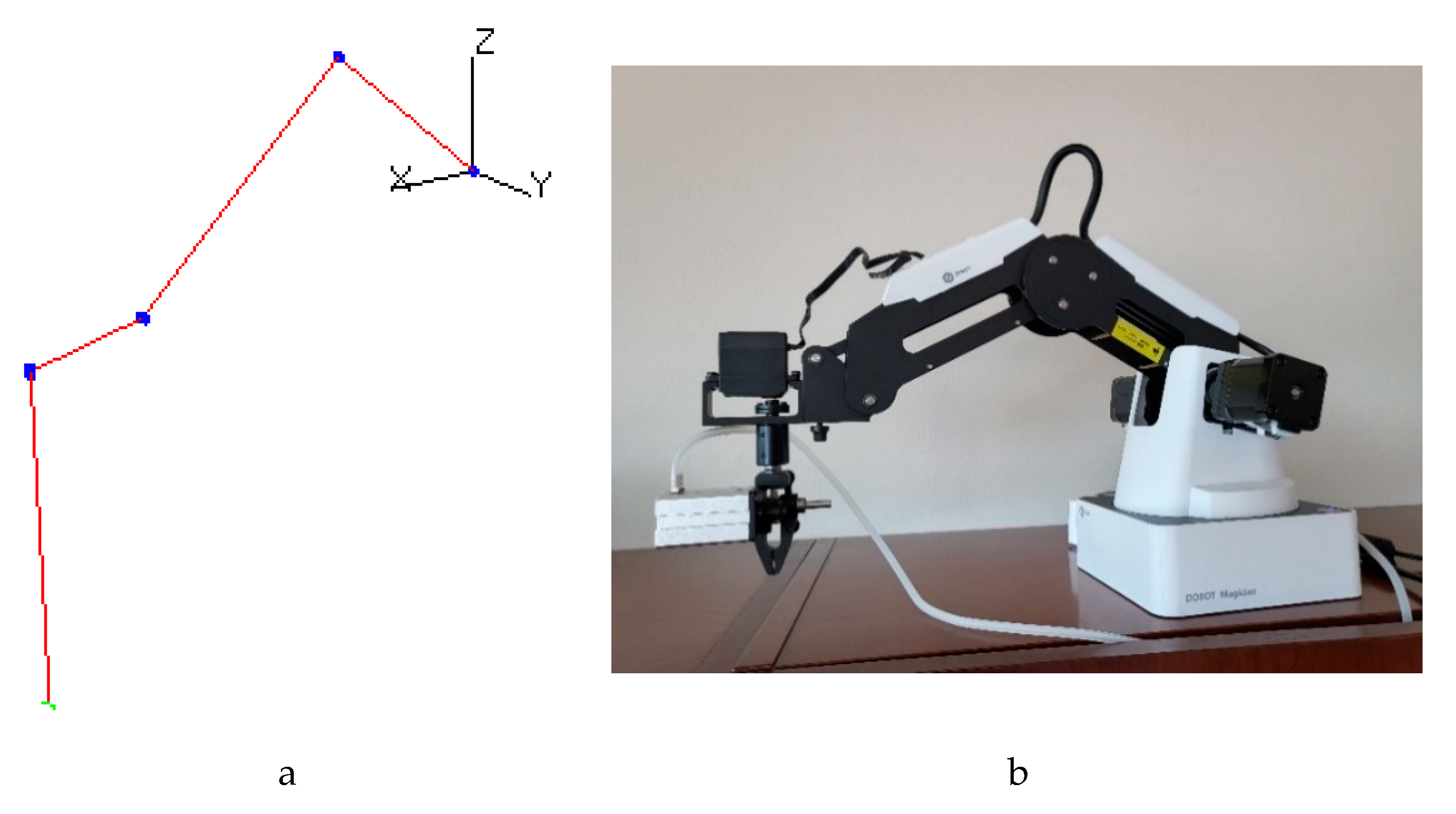
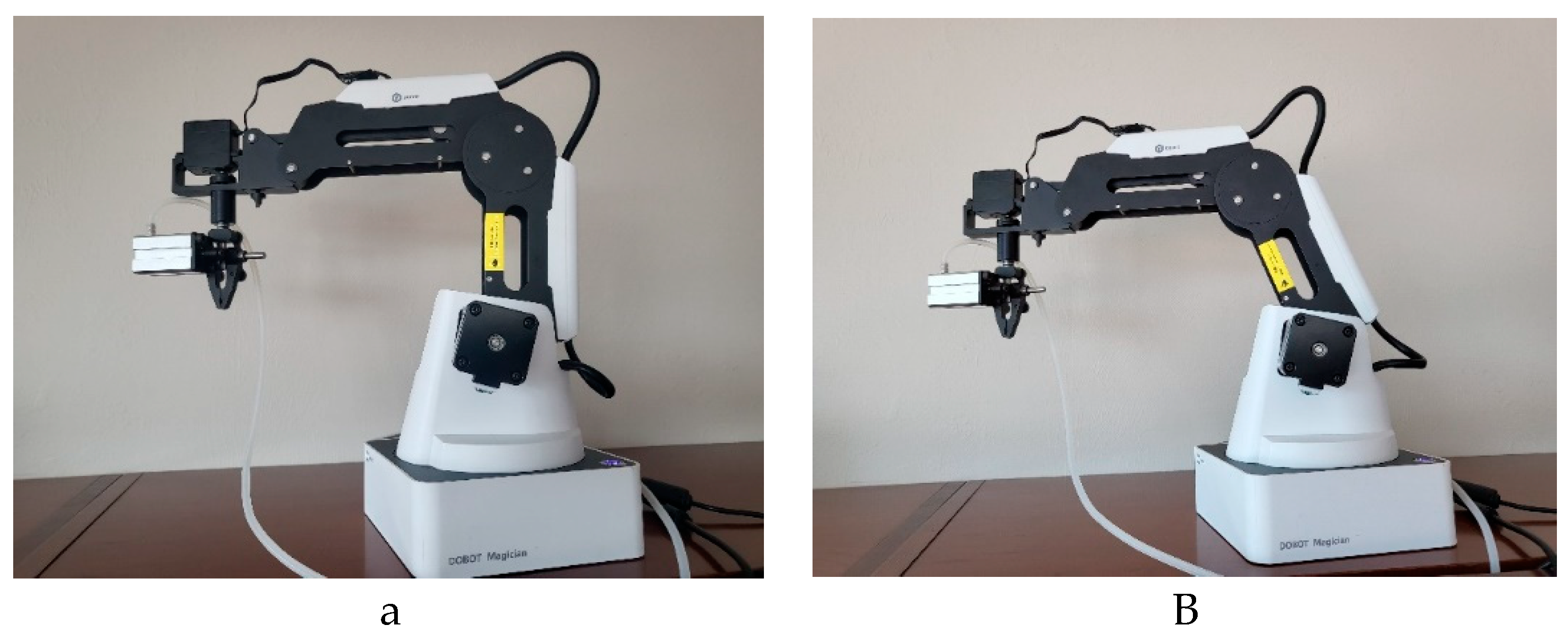
Figure 1,
Figure 2, and
Figure 3 show examples of the DOBOT arm tracking the virtual arm for different angles.
The simulation engine determines the location of the virtual arm at every cycle. The cycle executes 10 times per second. In each cycle the simulation engine determines the new location of each joint in the arm and renders the arm in its new location. It then communicates with the physical arm and provides the updated arm location.
Figure 4 shows the algorithm that is executed in every simulation cycle and
Figure 5 shows the computation of the velocity and position considering the modeled dynamics of the arm.
If the physical arm can be controlled at the joint level, the simulation engine will send it the set of newly computed joint angles. The physical arm can then move its joint motors using these angles. However, if the physical arm has a controller that does not allow direct access to its joint motors, then the location of the end-effector is given to the controller. The controller then computes all of its joint angles using its inverse kinematic equations and moves the arm accordingly. This works behind the scenes and is transparent to student’s view. The student programs each joint individually using joint programming and the physical as well as the virtual arm moves according to their program.
2.1. The DOBOT Arm
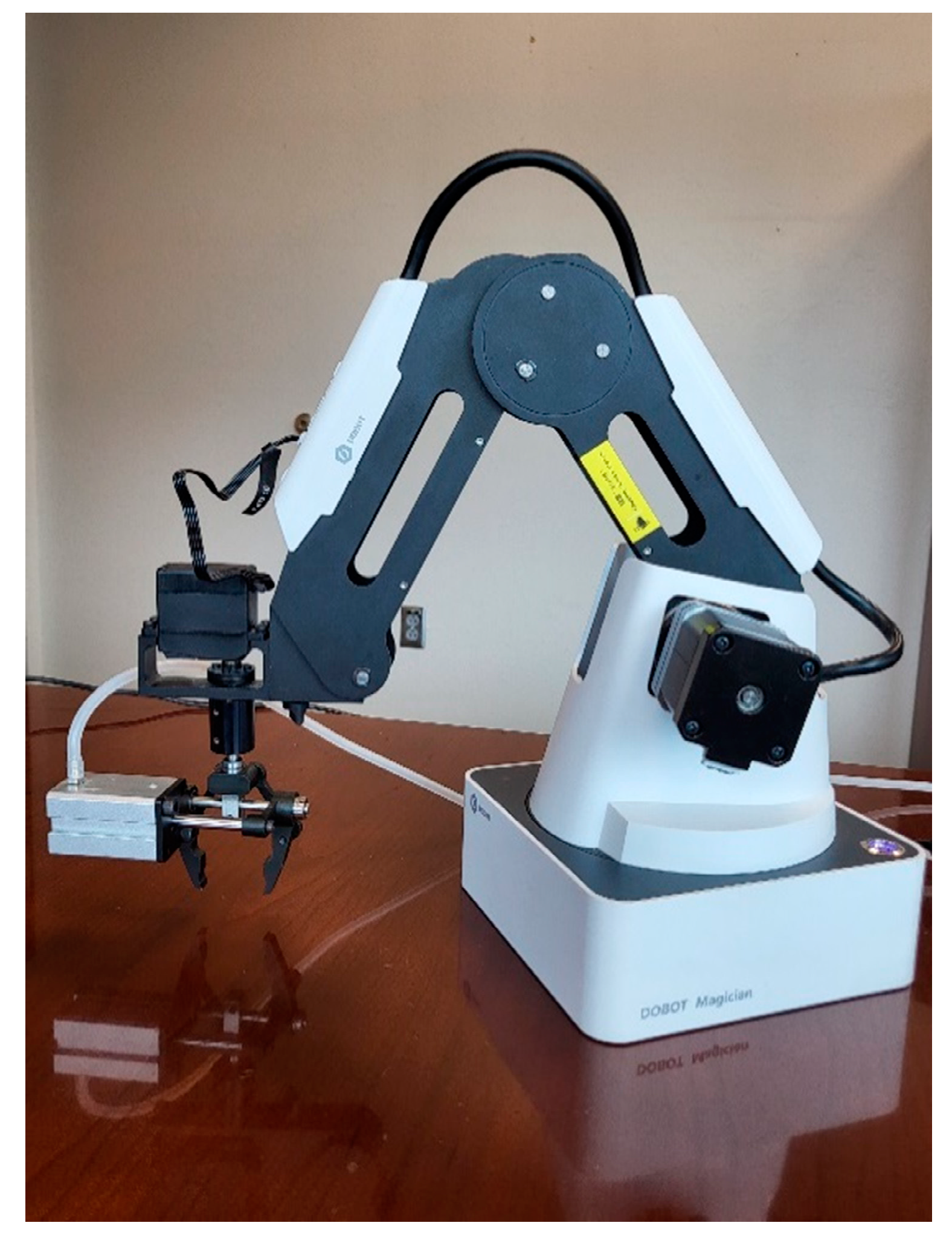
In our application we used the DOBOT Magician robotic arm, see
Figure 6, because it is small and inexpensive yet relatively strong and precise. The arm is made of steel and its joint motors are implemented using relatively large stepper motors. It appears to be of high quality will endure the use in the lab. It is designed mostly for educational purposes.
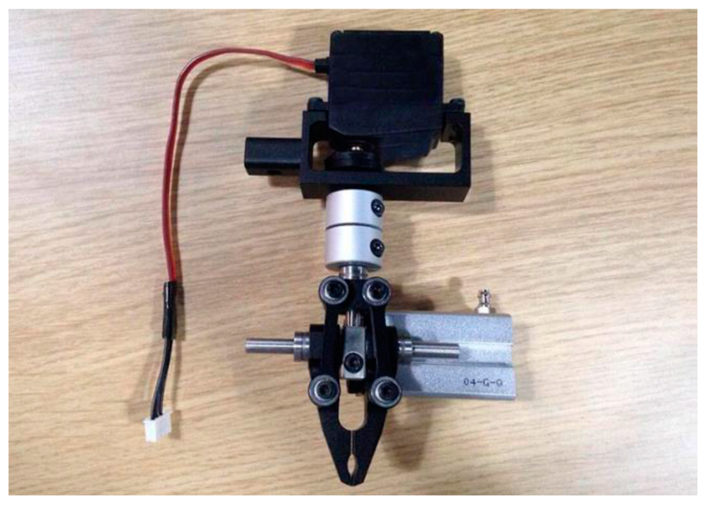
The kit includes a gripper and a suction cup for its end-effector. In our application the gripper was chosen since it can open and close as well as rotate see
Figure 7. The basic arm has 3 degrees of freedom (DOF), a rotating base, a rear arm and a fore arm. The rotating gripper is considered a 4
th DOF if its installed and since it opens and closes that adds half more resulting in a 4.5 DOF in the configuration used in our application.
The DOBOT comes with a controller that is implemented using an Arduino microcontroller that can get connected to a personal computer (PC) via a USB cable. It includes an Application Programming Interface (API) that runs on the PC and contains function calls to pass commands to the controller. The commands are generally used to move the arm.
The process of integrating the DOBOT arm is first to model the arm. That is, determine its DH parameters, the direction of rotation for each joint, and any characteristic that does not follow the DH convention. Then in the second step the communications between the virtual and the DOBOT arm is established.
2.1.1. The first step; modeling the DOBOT
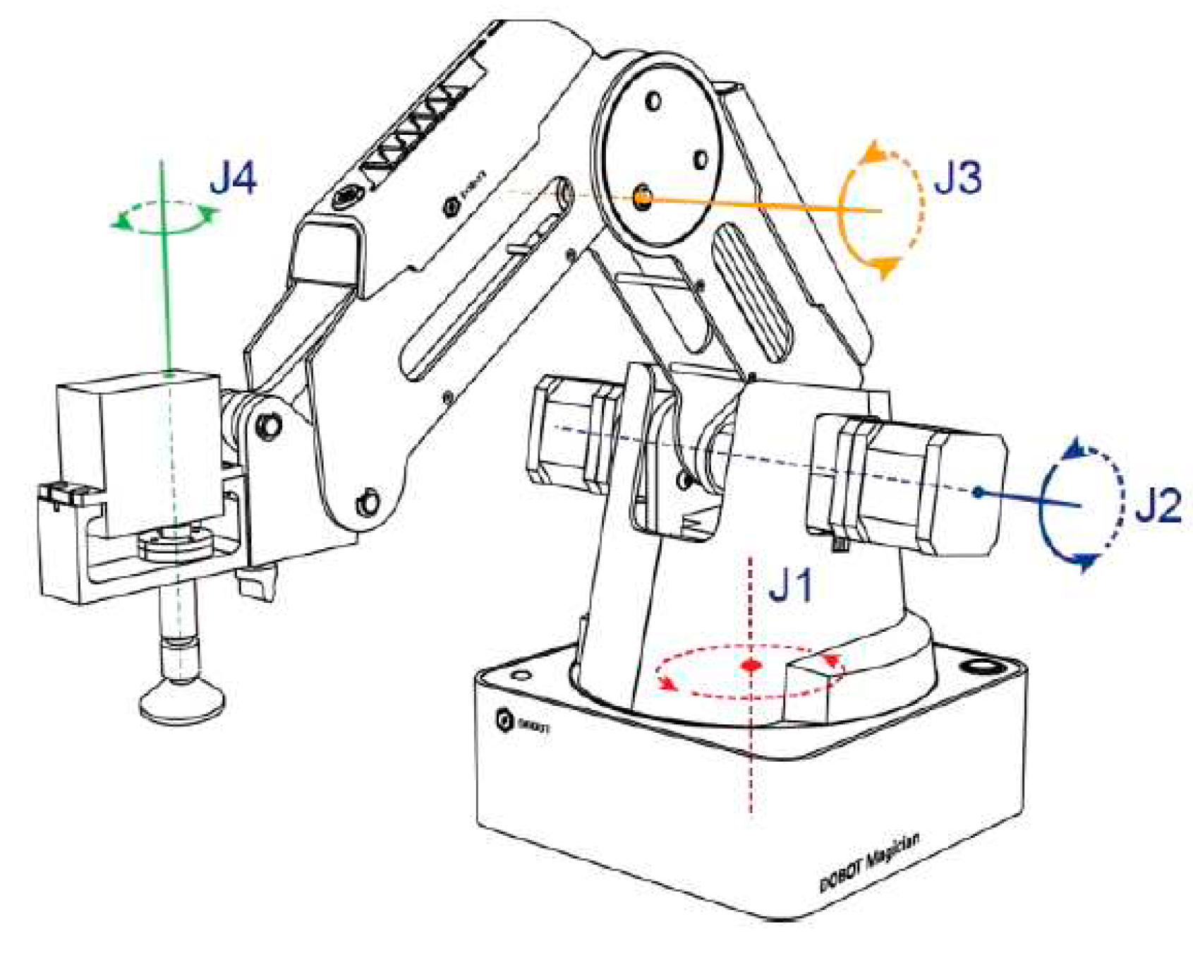
The first step in integrating the DOBOT arm to the software tool is to determine its DH parameters so we can create the virtual model. The three joints of the DOBOT are shown in
Figure 8. The direction of rotation is shown in
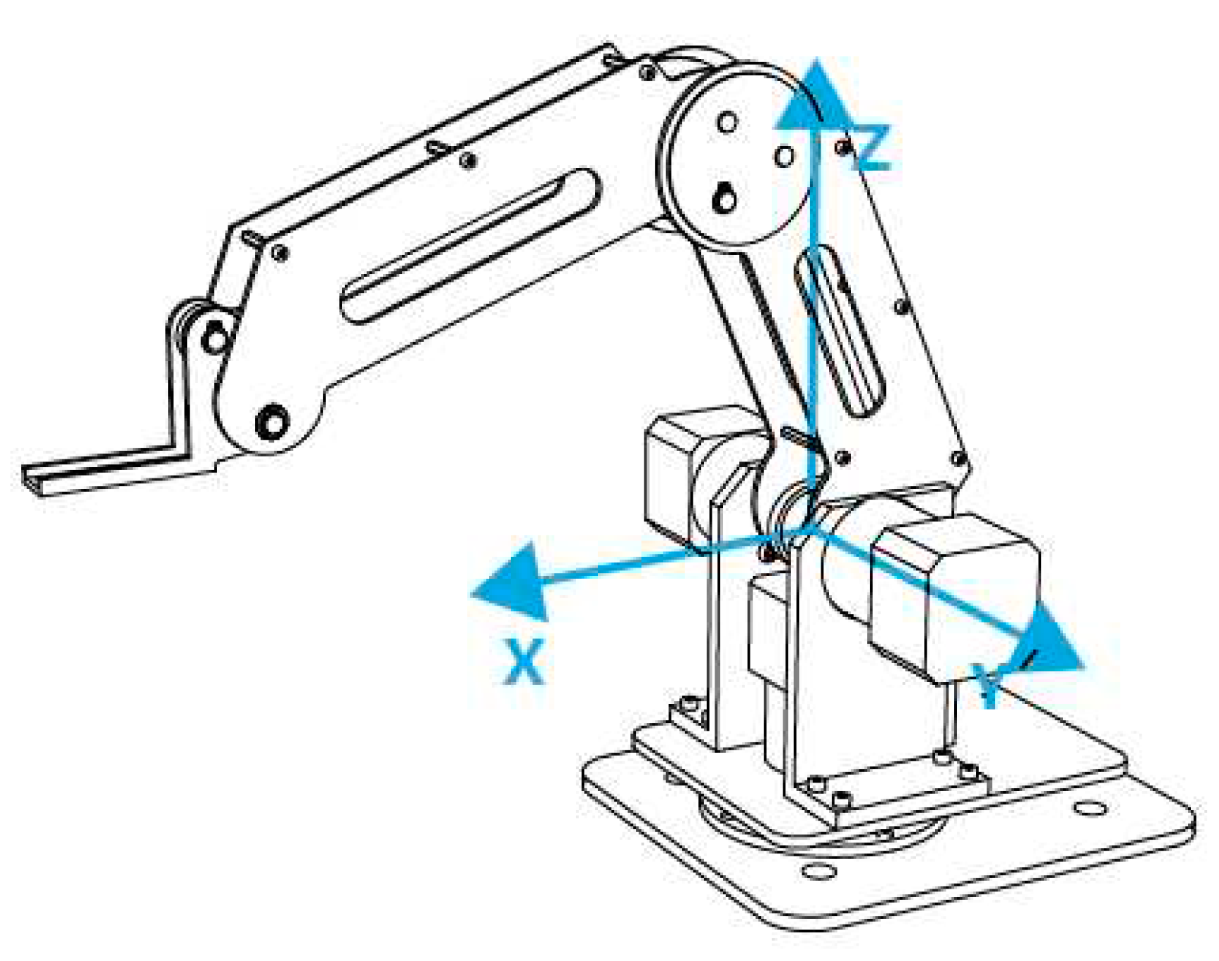
Figure 9 and the origin of its coordinate system is shown in
Figure 10. Note the origin is not at the base of the arm but rather at the intersection of the axis or rotation of joints one and two. The floor the arm is resting on is at a negative Z position.
The DOBOT arm has two mechanically moving joints. The rear arm rotates the fore arm in such a way that rotations of the rear arm does not change the orientation the fore arm has with respect to the world frame. The fore arm also has its own joint motor and can rotate independently. The resulting orientation of the fore arm is a function of its own joint angle and that of the rear arm. The wrist is also mechanically linked to the fore arm in such a way that the wrist is always horizontal. It does not have a separate joint like the fore arm so rotating it to change its pitch is not possible.
Figure 11 shows how the fore arm rotates with rotations of the rear arm such as to stay horizontal. Without considering the mechanically linked joint, the DH convention will place the fore arm rotating by the same angle as the rear arm since its orientation with respect to the rear arm will stay the same.
To accommodate the mechanical links to conform to the DH parameter convention, the fore arm joint is represented by two joints, one controllable and the other uncontrollable. Imagine that the fore arm’s joint motor is not mounted to the rear arm directly but rather to a plate. This plate is mechanically linked to the rear arm and rotates with rotations of the rear arm. The wrist is modeled as a joint that is not controllable but rather rotates with rotations of the fore arm. The DH parameters determined are represented in
Table 1 below.
The
added to theta 2 is to make the home position,
Figure 11 left, the position with all thetas equal to zero, point up as opposed to straight out horizontal. The
added to Theta 3 is to position the fore arm horizontal as opposed to straight up in the home position. The DH convention using the DH parameters shown in
Table 1 will have the rear arm and fore arm rotating in the opposite direction as the DOBOT so their angles must be negated. The software tool allows the user to enter the following information to model an arm, see
Figure 12:
The joint name
The joint type either revolute or prismatic
The direction or movement
Whether its controllable or uncontrollable
The four DH parameters
The range of motion for the joint
The maximum acceleration the joint can have and
The home position of the arm.
The DOBOT arm was added to the list of predefined arms so students only need to select the proper arm. Note the DOBOT is modeled as having 6 degrees of freedom as opposed to 4 since two uncontrollable mechanical joints were added to represent the mechanical linkages between some joints.
The only software enhancement required to model the DOBOT was the inclusion of a function to manage the uncontrollable joints. This function, executed in each simulation cycle, calculates the values of the uncontrollable joints based on the values of all the controllable joints. In the case of the DOBOT, it simply assigns the value of the controllable rear arm to the uncontrollable rear arm, and the value of the controllable fore arm to the uncontrollable fore arm.
2.1.2. The second step, establishing the communication protocol with the physical arm
The next stage of integrating the robotic arm into the software tool involved researching the various methods the controller can use to manipulate the arm. The arm comes with a built-in controller and an Application Programming Interface (API) that can be linked into the software tool. Control of the arm is achieved through API function calls. Three API functions were utilized for this purpose: Jog, Point-to-Point (PTP), and Continuous Path (CP). The API has a command queue, which ensures that existing commands are completed before new ones are initiated. Function calls are available to clear this queue. Three types of movement function calls were explored, each one implemented into the tool and made to track the virtual arm.
Jog: This function allows direct control of each joint, even allowing the user to input the desired velocity for the joint. However, only one joint can be controlled at a time by the user. Given that the real-world movement of an arm involves several joints moving at once, this method isn't effective as it stands. An attempt was made to make the joints move in sequence, albeit one at a time, with each clock cycle instructing a different joint motor to move. However, this resulted in a very jerky movement, accompanied by loud noise and significant vibrations. This is not how actual industrial arms operate, and such movement could cause damage to the arm over time. This method was therefore ruled out.
Point-to-Point (PTP): This method allows all joints to move concurrently and lets the user specify movements at the joint level. This method enables selection between the Cartesian space and joint space, with the latter being more suitable for this application. The input here is the desired new location, rather than the desired velocity. Every time a PTP movement is requested, the DOBOT’s controller creates a 2-1-2 type blend path, starting and ending with a velocity of zero and cruising at the specified velocity. However, the jerkiness issue persisted with the PTP method due to the requirement for each path to start and end with zero velocity and our tool operating in a cycle executed 10 times per second. Various remedies were tried, such as flushing the queue with every new PTP movement, and providing new movement commands before the completion of the last one. However, these fixes only resulted in intermittent improvements and the arm still had periods of sudden stops and starts.
Continuous Path (CP): Similar to the PTP method, this is designed for longer continuous movements. The API doesn't stop the arm when a movement is completed unless the command queue is empty. This resolves many issues the PTP method had, but it required movements to be specified in Cartesian space rather than joint space. Using the forward kinematic equations, the desired location of the end-effector in Cartesian space is computed and given to the API. This was the method used in our tool. For smooth arm movement, the velocity had to be greater than 100 degrees per second. Movement at a lower speed resulted in jerky motion, and movement at a higher speed made it hard for the API to keep up and the DOBOT would lag in movement. The main limitation was the USB communication that had to occur 10 times per second. However, in the comfortable range of 100 to 200 degrees per second, the DOBOT arm moved with smooth trajectories and was able to track the virtual arm effectively.
2.2. The Hitec servomotors
In [
1] we used a robotic kit from Pitsco, [
23], called the Tetrix Prime [
24] in a similar fashion. The students in this summer camp were of middle school age and they programmed the arm using a higher-level robotic language that does not involve joint programming. However joint programming can be used with these arms. In this application the students design and built their own arm. They measured the DH parameters and created the virtual arm that corresponds. Then they programmed the virtual arm using a dedicated robot language and their physical arm moved tracking the movements of the virtual arm.
In order for this integration to function effectively, a dedicated microcontroller was required. This microcontroller received information regarding the desired position of each joint and generated electrical signals to the Hitec servomotors. For this task, we employed an XPlained board by Atmel, which utilizes the Atmel XMEGA-A3BU microcontroller. However, microcontrollers used in Arduino or Raspberry Pi could be more suitable choices. The Arduino, for instance, also employs an Atmel microcontroller, albeit a smaller one, and is complemented by an operating system and programming environment that is generally easier for users to learn.
Many small robotic arms used for educational purpose and toys use the Hitec servomotors. They are cheap and can be easily controlled. The Hitec servomotor has three wires, a positive input voltage of 5V, a ground and the control signal. The control wire takes a pulse width modulated (PWM) wave as input where the duty cycle tells the angle the motor is to turn to. The PWM signal must be between 3 to 5 volts and cycle at 50 Hz. The motors we used has a
range, (
to
). The duty cycle range is from 4.5% to
to 10.5% for
.
Figure 13 shows an example of the input PWM wave needed to move the servomotor to
. The duty cycle must be 8.67% in this case or 1.73 ms high and 18.27 ms low. Note a frequency of 50 Hz corresponds to a period of 20 ms,
.
3. Results
The primary objective of this project is not merely to provide a platform for students to execute their joint programming projects, but rather to motivate them to complete these assignments. The educational software tool's virtual arm already serves as an adequate platform for students to develop and test their programs, effectively simulating a real arm, including large ones where dynamics must be considered. The integration with the DOBOT physical arm serves primarily to encourage students to complete their assignments - a goal it successfully fulfilled.
The course, CAP 4662 Introduction to Robotics, was offered in the Fall semesters of 2021 and 2022. In Fall 2021, the added feature of the DOBOT arm was not yet implemented, so students could only utilize the virtual arm. However, in Fall 2022, the new feature was added, integrating the DOBOT robotic arm into the tool. This allowed students to use the DOBOT arm in conjunction with this tool for their assignments. Homework 4 focused on joint programming, and homework 5 dealt with differential movements, both of which required the use of the DOBOT robotic arm. The remaining assignments did not involve programming or the use of the DOBOT arm. As shown in
Table 2, the completion rates for both Homework 4 and 5 increased by about 21% after the integration.
Some noteworthy points:
The grading for Homework 4 and 5 is based on participation. If a student makes a reasonable effort, they will receive the full grade. Consequently, the grades indicated for Homework 4 and 5 in
Table 2 represent the percentage of students who completed the assignments
The average completion rate for Homework 4 and 5 increased from 57.02% to 78.13%. This signifies an improvement of over 21%.
The average completion rate for the other assignments, excluding Homework 4 and 5, remained relatively unchanged from Fall 2021 to Fall 2022. This consistency suggests that the student cohort, environment, and other variables were similar across these two semesters. Therefore, the increased participation in Homework 4 and 5 can likely be attributed to the incorporation of the DOBOT.
Five DOBOT arms were made accessible to students in a supervised, open lab. Students were required to bring their own laptops equipped with the installed software tool and connect the DOBOT via a USB cable. The software's connection to the DOBOT is straightforward and reliable. To establish a connection, the student simply needs to switch on the DOBOT and click the 'Connect' button on the connection screen. Upon initiating the simulation of the virtual arm, it synchronizes with the DOBOT, which subsequently mirrors the movements of the virtual arm.
4. Discussion
The application of a robotic arm simulator that manifests a virtual arm possesses numerous benefits. These include providing a learning platform without the expenses and complications associated with operating a large industrial arm. The employment of industrial arms is often not feasible, as they typically prohibit direct manipulation of their joint motors, thus rendering joint programming infeasible. Small, cost-effective arms, while accessible, do not capture the dynamics of an industrial arm. Their lack of significant dynamics renders them ill-suited for joint programming exercises. However, using a physical arm, whether industrial or smaller educational models, delivers an authentic experience that can engage students, motivating them to complete assignments and enriching their overall course experience.
This paper introduces a hybrid solution where a small, inexpensive educational robotic arm is incorporated into our simulation-based educational tool, replicating the behavior of a heavy industrial arm. This offers the tangible experience of programming a real physical arm, bypassing the difficulties tied to utilizing a heavier industrial counterpart. This feat was achieved by synchronizing the small arm with the virtual arm, creating an illusion of the student programming the physical arm directly. The virtual arm simulates the dynamics and thereby imposes those hefty arm characteristics onto the smaller physical counterpart.
The Introduction to Robotics class was conducted in Fall 2021 using only the virtual arm, and later in Fall 2022 with the integrated physical arm. We noted that the class using the physical arm showed a completion rate of 78.13% on two joint programming assignments, which is a significant 21% increase from the 57.02% completion rate observed in the class that used only the virtual arm. No other assignment registered an increased completion rate, suggesting a comparable cohort of students.
Our future objectives include adapting the DOBOT's controller to support direct joint programming, which is anticipated to enhance the tracking process. Furthermore, we intend to improve the visualization of the virtual arm. The ultimate aim is to enable the virtual arm to emulate the physical arm with high fidelity, moving beyond its current simplistic representation
Funding
This research received no external funding.
Data Availability Statement
We are in the process of creating a release version of the educational software tool and will make it available when complete.
Conflicts of Interest
The authors declare no conflict of interest.
References
- Gonzalez, F.; Zalewski, J. An Educational Tool to Support Learning Robot Vision. Trans. Tech. STEM Educ. 2016, 1, 60–82. [Google Scholar]
- Gonzalez, F.; Zalewski, J. A New Robotics Educational System for Teaching Advanced Engineering Concepts to K-12 students. Computers in Education Journal 2016, 26, 61–73. [Google Scholar]
- Gonzalez, F.; Zalewski, J. Teaching Joint-Level Robot Programming with a New Robotics Software Tool. Robotics 2017, 6, 41. [Google Scholar] [CrossRef]
- Gonzalez, F. Learning Robot Differential Movements Using a New Educational Robotics Software Tool. In Education and Information Technologies; Springer Nature, 2022. [Google Scholar]
- Hitec Servos. Available online: https://www.hitecservos.com/ (accessed on 12 July 2023).
- Niku, S. Introduction to Robotics: Analysis, Control, Applications, 2nd ed.; Wiley: New York, NY, USA, 2011; ISBN 978-0-470-60446-5. [Google Scholar]
- Gonzalez, F.; Zalewski, J.; Pinzon, G. An Educational Tool to Support Introductory Robotics Courses. In Proceedings of the 122nd ASEE Annual Conference, Paper No. 13128. Seattle WA, USA; 14–17 2015.
- GAZEBO Robot Simulation Software. Available online: https://gazebosim.org/home (accessed on 14 July 2023).
- Robologix Logic Design Inc. Available online: http://www.robologix.com (accessed on 14 July 2023).
- Webots 7 Professional Mobile Robot Simulator. Available online: http://www.cyberbotics.com (accessed on 14 July 2023).
- Robotics Developer Studio. Available online: http://msdn.microsoft.com/en-us/library/bb648760.aspx (accessed on 14 July 2023).
- Schluse, M.; Priggemeyer, M.; Rossmann, J. The Virtual Robotics Lab in education: Hands-on experiments with virtual robotic systems in the Industry 4.0 era. 52th International Symposium on Robotics, 2020, pp. 1–8.
- Zhan, Z.; Zhong, B.; Shi, X.; Si, Q.; Zheng, J. The Design and Application of IRobotQ3D for Simulating Robotics Experiments in K-12 Education. Computer applications in engineering education. 2021, 30.2, 532–549. [Google Scholar] [CrossRef]
- Zhong, B.; Zheng, J.; Zhan, Z. An Exploration of Combining Virtual and Physical Robots in Robotics Education. Interactive learning environments ahead-of-print.
- Tijani, F.; Callaghan, R.; de Villers, R. An Investigation into Pre-Service Teachers’ Experiences While Transitioning from Scratch Programming to Procedural Programming. African journal of research in mathematics, science and technology education 2020, 24, 266–278. [Google Scholar] [CrossRef]
- Cheluszka, P. The Use of Low-Budget Self-Assembly Sets for Research and Robotics Education. Management systems in production engineering 2019, 27, 55–62. [Google Scholar] [CrossRef]
- Nutakki, C.; Vijayan, A.; Sasidharakurup, H.; Nair, B.; Achuthan, K.; Diwaka, S. Diwakar Low-Cost Robotic Articulator as an Online Education Tool: Design, Deployment and Usage. 2016 International Conference on Robotics and Automation for Humanitarian Applications (RAHA); IEEE, 2016; pp. 1–5. [Google Scholar] [CrossRef]
- Robinette, M.F.; Manseur, R. . ROBOT-DRAW, an Internet-Based Visualization Tool for Robotics Education. IEEE Trans. Educ. 2001, 44, 29–34. [Google Scholar] [CrossRef]
- Corke, P. MATLAB toolboxes: robotics and vision for students and teachers. IEEE Robotic and Automation Magazine 2007, 14. [Google Scholar] [CrossRef]
- Indri, M.; Lazzero, I.; Bona, B. Robotics education: Proposals for laboratory practices about manipulators. IEEE 18th Conference on Emerging Technologies & Factory Automation (ETFA), Cagliari, Italy, 2013; pp. 1–8. [Google Scholar] [CrossRef]
- Haddadin, S.; et al. The Franka Emika Robot: A Reference Platform for Robotics Research and Education. IEEE robotics & automation magazine 2022, 29, 2–20. [Google Scholar]
- DOBOT Magician. Available online: https://www.DOBOT.us/ (accessed on 12 July 2023).
- Pitsco Education. Available online: https://www.pitsco.com/ (accessed on 12 July 2023).
- Tetrix Prime. Available online: https://www.pitsco.com/Shop/Robotics (accessed on 12 July 2023).
Figure 1.
Example of the DOBOT tracking the virtual arm. (a) the virtual arm. (b) the DOBOT arm. The current positions for both arms are , , .
Figure 1.
Example of the DOBOT tracking the virtual arm. (a) the virtual arm. (b) the DOBOT arm. The current positions for both arms are , , .
Figure 2.
Example of the DOBOT tracking the virtual arm. (a) the virtual arm. (b) the DOBOT arm. The current positions for both arms are , , .
Figure 2.
Example of the DOBOT tracking the virtual arm. (a) the virtual arm. (b) the DOBOT arm. The current positions for both arms are , , .
Figure 3.
Example of the DOBOT tracking the virtual arm. (a) the virtual arm. (b) the DOBOT arm. The current positions for both arms are , , .
Figure 3.
Example of the DOBOT tracking the virtual arm. (a) the virtual arm. (b) the DOBOT arm. The current positions for both arms are , , .
Figure 4.
Algorithm to update the location of the end-effector. Its executed every 10th of a second.
Figure 4.
Algorithm to update the location of the end-effector. Its executed every 10th of a second.
Figure 5.
Algorithm to compute the position of a joint considering its maximum acceleration. DeltaTime is 0.01 seconds since the algorithm executes 10 times per second.
Figure 5.
Algorithm to compute the position of a joint considering its maximum acceleration. DeltaTime is 0.01 seconds since the algorithm executes 10 times per second.
Figure 6.
The DOBOT Magician robotic arm.
Figure 6.
The DOBOT Magician robotic arm.
Figure 7.
The gripper. The top black box is a Hitec servomotor that rotates the gripper and the bottom silver box is the air cylinder that opens and closes the gripper.
Figure 7.
The gripper. The top black box is a Hitec servomotor that rotates the gripper and the bottom silver box is the air cylinder that opens and closes the gripper.
Figure 8.
The joint coordinate system of the DOBOT.
Figure 8.
The joint coordinate system of the DOBOT.
Figure 9.
The direction of the joints.
Figure 9.
The direction of the joints.
Figure 10.
The origin of the coordinate system.
Figure 10.
The origin of the coordinate system.
Figure 11.
(a), the fore arm is horizontal. (b), the rear arm is rotated and the fore arm rotates to maintain its horizontal orientation with the horizon.
Figure 11.
(a), the fore arm is horizontal. (b), the rear arm is rotated and the fore arm rotates to maintain its horizontal orientation with the horizon.
Figure 12.
The user input screen used to specify the kinematics and dynamics of the arm.
Figure 12.
The user input screen used to specify the kinematics and dynamics of the arm.
Figure 13.
(a) the PWM signal used to move the servomotor's position to 35 degrees, (b) the calculation for computing the required duty cycle for a 35-degree angle.
Figure 13.
(a) the PWM signal used to move the servomotor's position to 35 degrees, (b) the calculation for computing the required duty cycle for a 35-degree angle.
Table 1.
DH parameters for the DOBOT Magician arm. Units are in mm and degrees.
Table 1.
DH parameters for the DOBOT Magician arm. Units are in mm and degrees.
| Link name |
Theta |
d |
a |
Alpha |
| Base |
Theta 1 |
0 |
0 |
90 |
| Rear arm |
90 + Theta 2 |
0 |
135 |
0 |
| Fore Arm Mech |
|
0 |
0 |
0 |
| Fore arm |
-90 + Theta 3 |
0 |
147 |
0 |
| Wrist Mech |
|
0 |
59 |
90 |
| Gripper |
Theta 4 |
110 |
0 |
0 |
Table 2.
The homework grades for the Fall 2021 and the Fall 2022 in Introduction to Robotics.
Table 2.
The homework grades for the Fall 2021 and the Fall 2022 in Introduction to Robotics.
| Semester |
HW 1 |
HW 2 |
HW 3 |
HW 4 |
HW 5 |
HW 6 |
HW 7 |
Average All other HW |
Average
HW 4 & 5 |
| Fall 2021 |
92.59 |
88.46 |
80.77 |
55.77 |
58.27 |
79.81 |
65.38 |
81.40 |
57.02 |
| Fall 2022 |
81.25 |
81.25 |
81.25 |
75.00 |
81.25 |
81.25 |
81.25 |
81.25 |
78.13 |
|
Disclaimer/Publisher’s Note: The statements, opinions and data contained in all publications are solely those of the individual author(s) and contributor(s) and not of MDPI and/or the editor(s). MDPI and/or the editor(s) disclaim responsibility for any injury to people or property resulting from any ideas, methods, instructions or products referred to in the content. |
© 2023 by the authors. Licensee MDPI, Basel, Switzerland. This article is an open access article distributed under the terms and conditions of the Creative Commons Attribution (CC BY) license (http://creativecommons.org/licenses/by/4.0/).
