1. Introduction
Tracking a moving ground target is one of the important capabilities of UAVs [
1]. Making the tracking process automatic and free of human intervention is essential for reliving the burden on UAV operators and improving the efficiency and safety of UAV missions. The goal of this paper is to develop a control scheme that allows multiple fixed-wing UAVs to cooperatively track a moving ground target in unknown windy conditions.
Target tracking using multiple fixed-wing UAVs remains a challenge. On one hand, the motion of fixed-wing UAVs is subject to various input constrains. To prevent stalling, a fixed-wing aircraft cannot hover and must maintain a positive forward airspeed. Accordingly, the UAVs must fly in a circle around the ground moving target [
2]. On the other hand, to avoid collisions and to ensure that the sensors can cover the target, the UAVs need to be evenly distributed around the target and maintain a certain phase interval [
3]. The standoff tracking is a possible solution for target tracking using a team of fixed-wing UAVs. In this pattern, the UAVs keep a certain distance (called standoff radius) from the target and moves in a circular motion (termed standoff circle) at a proper altitude relative to the target.
In cooperative target tracking missions with unknown wind, three main technical issues should be considered: (1) Relative distance regulation, which focuses on how to enable the UAVs to converge to a circular orbit with prescribed standoff radius around the target by controlling their headings [
4]. (2) Intervehicle phase separation, which focuses on the distributing the loitering UAVs uniformly over a standoff circle with certain angular phase difference by controlling their airspeeds [
5]. (3) Background wind resistance, which focuses on how to achieve robust stability for UAVs performing standoff tracking in the presence of wind and target motion [
6].
Relative distance regulation, which aims to steer the UAV to a circular orbit around the target, is the key to achieve standoff tracking of a moving target by a single UAV. Typically, a guidance law is proposed to regulate the position of the UAV on a predefined circular path. The path usually guides the UAV to circle around a ground moving target at a constant distance. Consequently, the UAV trajectory can be expressed as a circle with predefined standoff radius in the target’s frame. There are various types of the guidance law, including reference point guidance (RPG) [
7,
8,
9], Lyapunov guidance vector field (LGVF) [
10,
11,
12,
13,
14] and so on. Based on a predefined target tracking path, the standoff tracking problem of a ground moving target can be converted into a path following problem [
7]. For example, in [
8] and [
9], a nonlinear guidance law is proposed to achieve path following for curved path. In this approach, each point on the curved path is designated as a reference point, and a lateral acceleration command is generated to drive the UAV to the reference point. However, due to the ground target moving speed is usually much slower than that of the UAV, the RPG method cannot be directly applied to the standoff target tracking problem. As a new form of potential filed, the LGVF is introduced to guide the UAVs to achieve standoff target tracking. In [
10], a LGVF is proposed for loiter maneuver around a stationary target. This approach also enables moving target tracking, but it may lead to slow convergence due to constant curvature in the LGVF. To shorten the convergence time, literature [
11] combines the tangent with the LGVF, while literature [
12,
13] add the circulation parameter
c into the original LGVF. The shape of LGVF can be adaptively adjusted by changing the circulation parameter. In this way, a faster convergence to the standoff circle can be achieved due to a higher contraction component. Based on the works of [
12,
13], an offline optimal parameter searching method is presented for selecting the optimal guidance function to shorten the convergence time in [
14]. However, this approach has such heavy computational load that it cannot be extended to real-time application scenarios. Although these above methods have been verified to be feasible for the single UAV standoff tracking problem, they only focus on the optimization of LGVF without considering the input constraints of fixed-wing UAV, such as heading rate limitation. If the curvature of the LGVF is too large, the actual trajectory of UAV cannot converge to a standoff circle due to the saturated rudders. Therefore, it is still necessary to design a control law for regulating the relative distance while satisfying the turning rate limitation.
The performance of target localization algorithm is significantly impacted by the relative sensor-target geometry. Observation configurations, or different sensor-target geometries, produce varying estimation error ellipses of target location algorithm. It is worth considering which observation configuration can yield the best target localization results. By minimizing the Cramer-Rao lower bound (CRLB), which provides a lower bound on estimator performance, the uncertainty in estimation process can be reduced. Therefore, literature [
15] utilizes the determinant of CRLB to determine the observation configuration that results in a minimal measure of the uncertainty ellipse. According to the conclusions in [
15], if only two UAVs perform standoff tracing mission, the intersection angle subtended at the target (called phase separation angle) by two UAV will be
; if the number of UAVs is
N ≥ 3, the phase separation angle between adjoining UAVs will be
. An optimal configuration should position UAVs at equal angular intervals around the perimeter of the standoff circle. This requires the phase separation in the coordinated standoff tracking problem. Various phase separation methods have been proposed, including model predictive control (MPC) [
16,
17], sliding mode control (SMC) [
18,
19], conical pendulum motion [
20], consensus algorithm [
21,
22,
23,
24] and so on. In [
16,
17], a nonlinear MPC framework for coordinated standoff tracking by two UAVs is proposed The optimal control outputs for speed and turning rate are generated by minimizing the sum of weighted cost functions that include standoff-distance regulation error and phase separation error in a receding horizon. However, as the number of the UAVs increases, the computational complexity and iterative time required for searching optimal results also increase. In [
18], a loitering algorithm based on sliding mode control is presented to control the virtual leader’s position on a standoff circle centered at the ground moving target. However, the SMC method suffers from chattering due to the discontinuity of the signum function in the control law. To eliminate chattering, the signum function is replaced by a saturation function in literature [
19]. However, both literature [
18,
19] ignore the vehicle airspeed constraint. The airspeed of the fixed-wing UAV is restricted within lower and the upper bounds. In order to satisfy the airspeed boundary constraint, literature [
20] proposes that the UAV reduces its speed by decreasing the standoff radius when flying on the right-hand side of the target and its airspeed reaches the upper bound. Conversely, the UAV increases the standoff radius to increase its airspeed when its airspeed reaches the lower bound. However, this approach causes the distance between the UAV and the target to oscillate, leading to failure in achieve the control objectives of the cooperative standoff target tracking problem. Different from the integrated controller in [
20], the heading control channel and velocity control channel are decoupled in [
21,
22,
23,
24]. The space phase angle is chosen as the coordination variable of the consensus algorithm, allowing for the design of cooperative airspeed controllers for the UAVs. The phase separation angles among the UAVs can asymptotically convergence to the same one, reflecting equal space separation. However, the airspeed constraint is not taken into account in the space phase separation method. Furthermore, the phase separation angles wrapped in
are discontinuous, and will lead to oscillating airspeed control input. It is not beneficial for reducing the space phase separation error. Therefore, it is critical to design a phase separation controller that provides a smooth signal output and meets the airspeed constraint of UAVs in the coordinated standoff tracking problem.
Most of the research mentioned above assumes an ideal non-wind environment or a known constant background wind. However, in practice, background wind is usually present and it affects the performance of the UAVs, especially when the background wind is unknown. In [
25], a robust term is added to the standoff tracking control law to obtain disturbance rejection for wind-gust. However, the response time of the robust controller is too long and unsuitable for highly maneuvering target tracking. To quantitatively describe wind dynamics, a simple conservative model (e.g. sine function as in [
26] or linear model as in [
27]) or a more sophisticated one (e.g. stochastic as in [
28]) can be used. In [
28], Dryden model [
29] and Davenport model [
30] are used to describe the dynamics of wind in high altitude or near the ground, respectively. The unscented Kalman Filter (UKF) is introduced to estimate the velocity of background wind. However, the accuracy of the wind speed estimation largely depends on the accuracy of the constructed wind dynamic model. In reality, wind is stochastic and time-varying, which makes it difficult to be modeled. In literature [
31], an adaptive estimator is utilized to estimate the wind velocity. In the case of a stationary target without wind, the vehicle trajectory converges to a circle orbit (called perfect trajectory or orbit) by implementing a designed standoff tracking control law. However, for a moving target with wind, the actual trajectory cannot converge to the perfect one due to the disturbance caused by the wind and target motion. The wind velocity estimation can be obtained by reducing the offset between the actual vehicle trajectory and the perfect trajectory. However, the convergence rate of the estimator is slow because it only uses the radial distance of the offset. Therefore, designing a wind velocity estimator that has high accuracy and fast convergence rate remains challenging.
This paper addressed the challenges of cooperative standoff target tracking using multiple fixed-wing UAVs with input constraints and the considerations of unknown background wind and target motion. The controllers satisfying the input constraints, such as heading rate and airspeed limitation, are designed to guarantee a team of fixed-wing UAVs to perform efficiently during coordinated standoff tracking missions. The major contributions of the paper are as follows: (1) A heading rate control law based on LGVF is proposed. We prove that this proposed heading rate controller can guarantee that the UAV can asymptotically converge to a standoff circle loitering the target under arbitrary initial conditions of the position and heading. To satisfy the limitation of heading rate, the minimum allowable standoff radius is formulated; (2) In order to avoid the discontinuity of space phase angle, a new term called temporal phase is proposed to represent the phase separation. An airspeed control law is introduced to steer a team of UAVs maintaining an optimal observation configuration, which requires distribution around the standoff circle with equal phase separation. Rigorous proofs for global convergence and satisfying airspeed limitation using the proposed speed controller are provided. (3) The target motion and background wind are regarded as external disturbance. The offset vector caused by external disturbance between the actual trajectory and the perfect/desired orbit is utilized to estimate the composition velocity of background wind and target motion. We prove that the estimation result of the proposed estimator asymptotically converges to the true value of the composition velocity.
The remainder of this paper is structured as follows. Sec. 2 presents problem formulation, including assumptions made in this study, a UAV kinematic model with control input constraints, and control objectives. Sec. 3 discusses the problem of standoff tracking using a single UAV. Based on the LGVF, a lateral controller with heading rate input constraint is proposed to regulate the position of a UAV on a circle around the target under the condition of arbitrary initial position and heading. In Sec. 4, we introduce a term called temporal phase to represent the spatial distribution of the UAVs on the standoff circle, and propose cooperative controllers with airspeed input constraint to achieve desired temporal phase separation. In Sec. 5, an online estimator is developed to adapt the proposed heading rate and airspeed controllers to the case of a moving target in the presence of wind. Simulation and experimental results are demonstrated in Sec. 5, followed by summary and conclusions in Sec. 6.
4. Cooperative Standoff Tracking Using Multiple UAVs
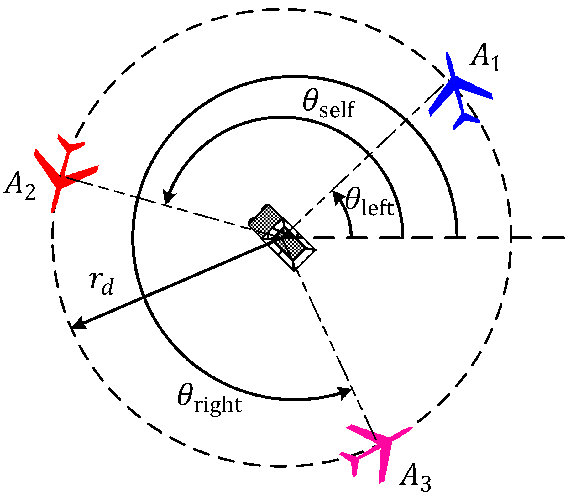
When a team of UAVs is used to track a ground moving target, coordination between aircraft is necessary to avoid collisions and to maximize sensor coverage of target. A possible solution to this coordination problem is the so-called “phase separation” approach whereby the UAVs fly along the standoff circle with equal intervehicle phase separation angle with respect to its neighbors. Literature [
25] proposes a space phase separation algorithm (SPSA) to achieve desired angular spacing as illustrated in
Figure 3.
As shown in
Figure 3, three UAVs are distributed counterclockwise in the standoff circle according to the ascending sequence of their unique identity numbers
. Each UAV
independently calculates its airspeed control input
, based on its own phase angle
, the phase angle
of its left neighbor
, and the phase angle
of its right neighbor
. For
, its left neighbor is
and its right neighbor is
. For
, its left neighbor is
and its right neighbor is
.
In [
25], the space phase separation angle of
,
, is defined as
. Similarly, the phase separation angle of the right neighbor
is defined as
. The space phase separation error of
,
, is defined as
. Similarly, the space phase separation error of the right neighbor
is defined as
. Thus, the airspeed control input of
can be designed as
. Where
,
represents the relative distance between
and the target.
represents the desired airspeed when the team of UAVs loiter around the target with along a standoff circle synchronously. In this paper,
is called standoff speed for short.
However, the SPSA method proposed in [
25] has two disadvantages. (i) The airspeed limitation as shown in Equation (2) is not considered in SPSA; (ii) The space phase separation
and corresponding error
are wrapped in
, and thus they are discontinuous. This discontinuity will lead to the oscillation of airspeed control input, and then result in a poor tracking performance of the UAVs. This shortcoming has been confirmed in simulation results of Figure 9 in [
25]. In order to avoid the discontinuity of space phase angle, the space phase is replaced by a new notion called temporal phase, which can be also used to represent the distribution of the UAVs on the standoff circle. Based on the temporal phase, a new temporal phase separation algorithm (TPSA) is proposed to achieve desired temporal phase separation in cooperative standoff target tracking mission.
4.1. Airspeed Controller Design for Temporal Phase Separation
In SPSA method, the angle
is utilized to represent the space phase of the UAV
. The space phase describes the distribution of the UAVs which keep a circle around the target. Similarly, we can also introduce temporal phase to equivalently describe the distribution of the UAVs. The temporal phase of
is defined as follows
where
represents temporal phase of
.
is the desired relative speed of
with respect to the target, and can be expressed as follows.
where
represents the desired heading when
flies along the standoff circle.
In Equation (44), represents the time required for the UAV to complete a circle of flight along the standoff circle with the desired airspeed . is used to normalized the flight time of the UAV, and is defined as . It can be observed from (44) that, the temporal phase represents the normalized time required for the UAV to fly from space phase angle 0 to the current space phase angle along the standoff circle.
Therefore, the temporal phase separation between
and its neighbor is defined by the difference of their temporal phase.
Suppose there are
UAVs, a leader-follower formation strategy is used in this paper. Without loss of generality, it assumes that
is the leader and its airspeed is the desired one, e.g.,
, and is held constant. Then,
follows
, and adjusts its airspeed to achieve the desired temporal separation with its leader
. Similarly,
follows its leader
, and achieves the desired temporal separation by varying its airspeed. The temporal separation error is defined as follows
where
represents the desired separation. The airspeed input is designed as follows
where
represents the airspeed increment of the UAV in one time step, and it reflects the performance of the onboard autopilot.
Before verifying that the proposed controller (49) always satisfy the min and max airspeed constraint (2), Assumption 5 is introduced as follows:
Assumption 5.
There exists appropriate values of and, so that the following constraints are satisfied, and.
Remark 7.
Generally speaking, the airspeed of the UAV is always faster than the target speed and the wind speed, thus theconstraint, , could be satisfied. In addition, the is depended on the performance of the autopilot, which definitely satisfies the requirement of . Therefore, Assumption 5 is reasonable. Based on Assumption 5, the following Theorem 4 is proposed.
Theorem 4.
If the standoff speed and the speed increment are satisfy the inequality conditions presented in Assumption 5, then the proposed controller given by (49) always satisfy the min and max airspeed constraint given by (2).
Proof. According to (49), let
, where
and
. Due to
, then
and
. If
, then
, i.e.,
.
Considering
, it yields that
Substituting Equation (50) into Equation (51), it yields that
According to Assumption 5, it is obtained that, , which implied that . Therefore, it can be concluded that the proposed airspeed control law given by Equation (49) always satisfy the min and max airspeed constraint given by Equation (2). Thus, the proof for Theorem 3 is completed. □
4.2. Stability Analysis of Airspeed Control Law
Stability analysis of airspeed control law is provided in the following Theorem 5.
Theorem 5.
For the relative motion model of UAV described in (9) if the heading rate control law given by Equation (24) and the cooperative airspeed control laws given by Equation (49) are applied to a team of UAVs, then each aircraft can achieve equal temporal separation and fly along the standoff circle, i.e. as , , .
Proof. Differentiating Equation (48) with respect to time
, it yields that
According to the relative motion model given by Equation (9), one obtains
Suppose that the aircraft
(
) implementing the proposed heading rate control law given by (24) has been converged on the standoff circle, i.e.,
. Therefore,
Let
, we obtain
According to the cooperative airspeed control laws given by (49), one has
Substituting Equation (57) into Equation (56), it yields that
where
. Substituting (58) into (55) and setting
, it yields that
Let
and
, one derives
It is easy to prove that the cascade connected system shown in (60) is asymptotically stable, i.e., as . Thus, the proof for Theorem 5 is completed. □
7. Conclusions
This paper investigates the standoff tracking of a ground moving target using multiple fixed-wing UAVs in unknown background wind. The main contribution of this paper is to develop a cooperative standoff target tracking algorithm (CSTTA), which considers the control input constraints of the fixed-wing UAV, target motion, and unknown wind. Following conclusions can be obtained.
(i)A fundamental cooperative standoff target tracking problem include three control objectives: relative distance regulation, relative course convergence and intervehicle phase separation. In addition, in the case of unknown background wind, it is essential to enhance the wind resistance capacity of the UAV.
(ii)A heading rate control law based on LGVF is introduced to regulate the position of a UAV on a circle around the target with a constant standoff distance. It is proved that the proposed heading rate controller can achieve standoff target tracking for a single UAV in the condition of arbitrary initial position and heading. Due to the heading rate input is constrained, the predefined standoff distance between UAV and target has allowable lower bound. The minimum allowable standoff distance is formulated in this paper.
(iii)A new temporal phase separation algorithm (TPSA) is proposed to achieve desired temporal phase separation in cooperative standoff target tracking mission. The TPSA approach takes into account the min and max airspeed constraint, and can avoid the discontinuity of wrapped space phase angle. The results of comparison simulations show that, the TPSA has smaller convergence error and faster convergence rate than the previous space phase separation method.
(iv)The offset between the actual vehicle trajectory and the desired LGVF orbit can be utilized to estimate the composition velocity of target motion and background wind. The results of comparison simulations show that, the proposed composition velocity estimation algorithm (CVEA) can effectively estimate the composition velocity, and thus enhance the tracking performance of the UAVs in the presence of background wind and target motion.
There are many potential directions for future consideration. First, the current models and algorithms will be extended to the three-dimensional coordinates. Second, the proposed algorithms will be implemented on real UAVs in the future works. Third, the more complex mission environment will be considered, and the methods of terrain obstacle and intervehicle collision avoidance will be introduced to enhance aircraft safety. Finally, the communication constraints, such as limited communication range and communication delays, will be considered.
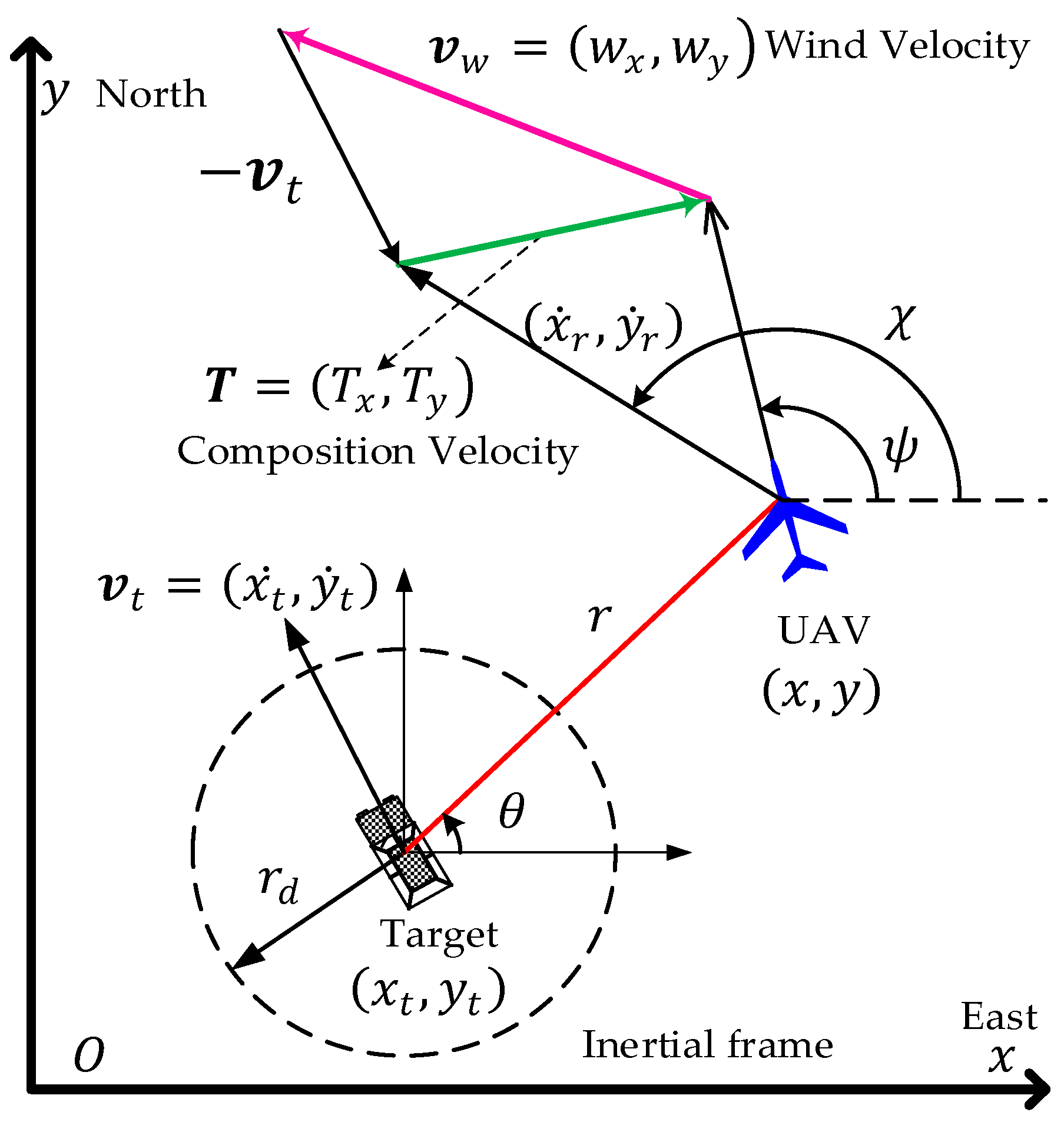
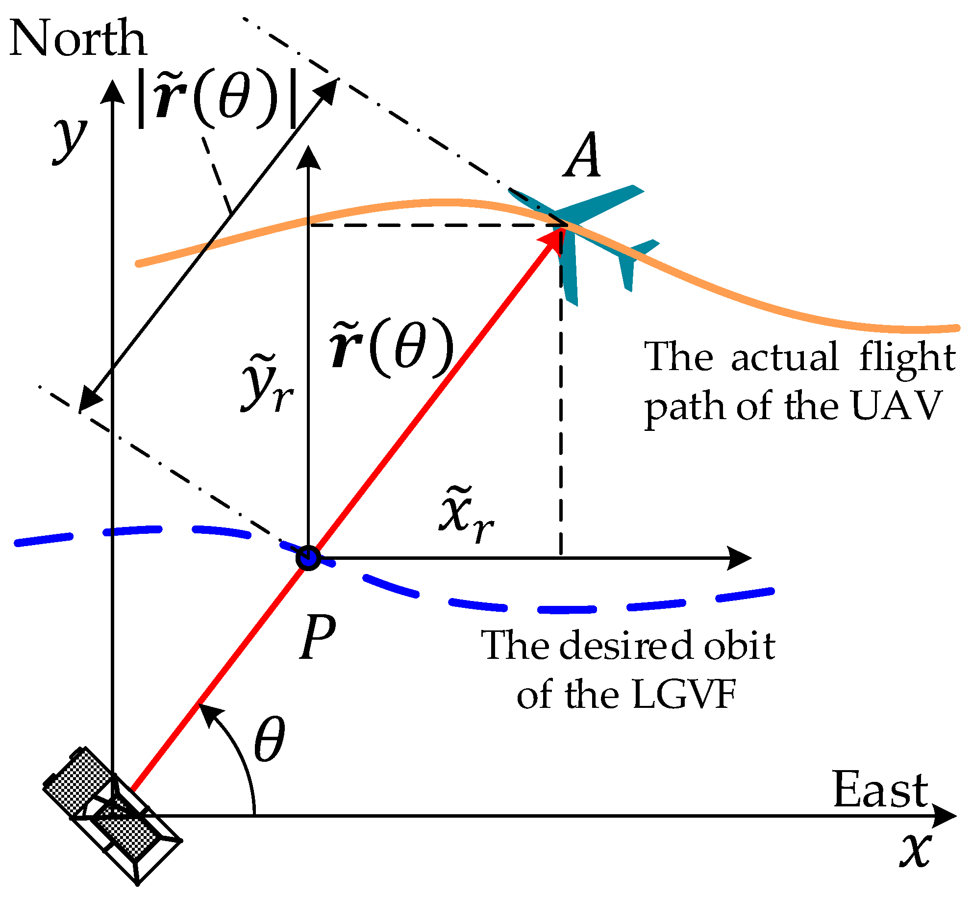
Figure 1.
Geometry of ground target tracking in wind.
Figure 1.
Geometry of ground target tracking in wind.
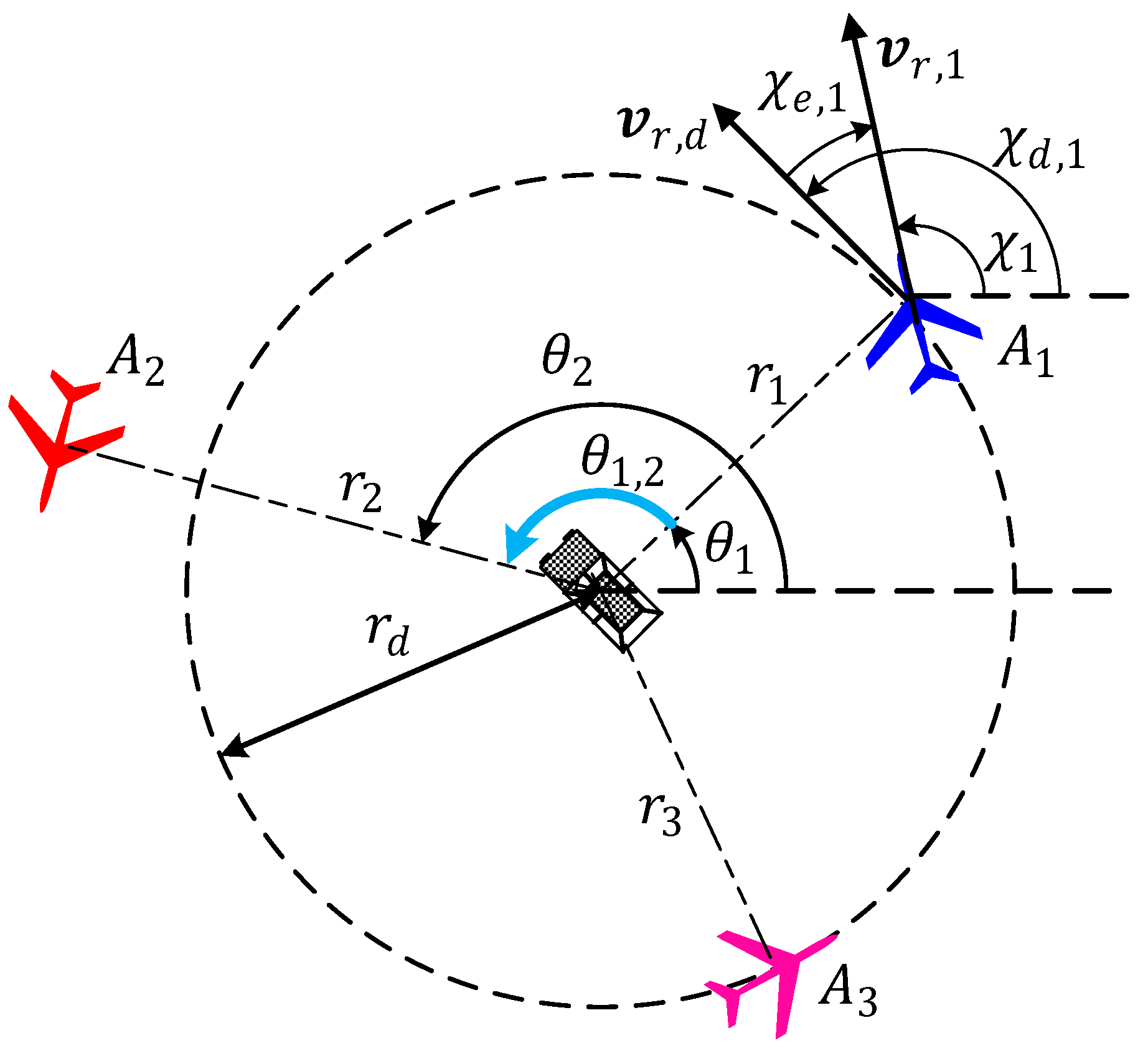
Figure 2.
Illustration of cooperative standoff target tracking.
Figure 2.
Illustration of cooperative standoff target tracking.
Figure 3.
Illustration of phase separation control for UAVs.
Figure 3.
Illustration of phase separation control for UAVs.
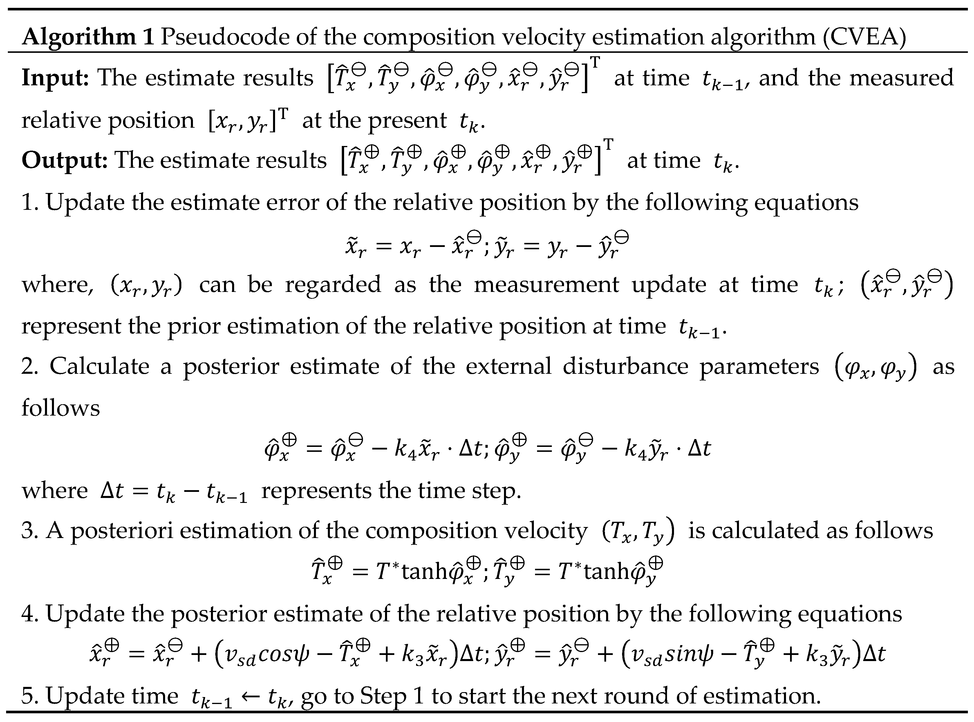
Figure 4.
Pseudocode of the composition velocity estimation algorithm (CVEA).
Figure 4.
Pseudocode of the composition velocity estimation algorithm (CVEA).
Figure 5.
Principle of CVEA.
Figure 5.
Principle of CVEA.
Figure 6.
Trajectories of UAVs and target in inertial coordinates (scenario 1).
Figure 6.
Trajectories of UAVs and target in inertial coordinates (scenario 1).
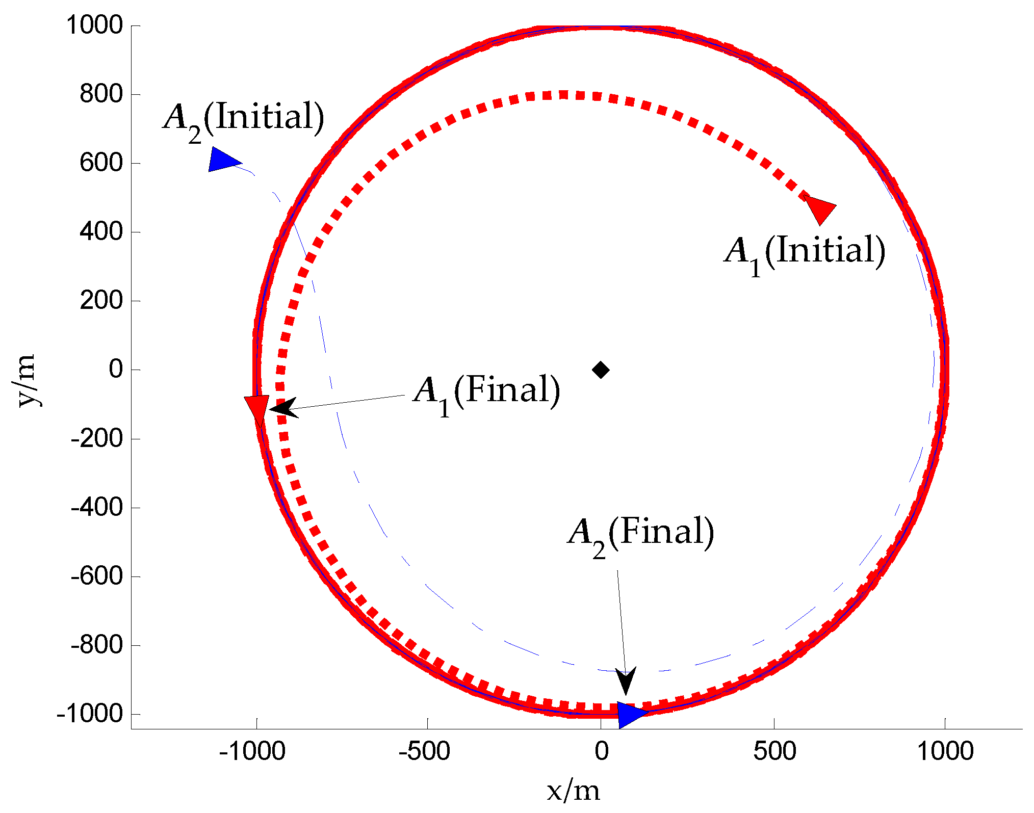
Figure 7.
Trajectories of UAVs in local target frame coordinates (scenario 1).
Figure 7.
Trajectories of UAVs in local target frame coordinates (scenario 1).
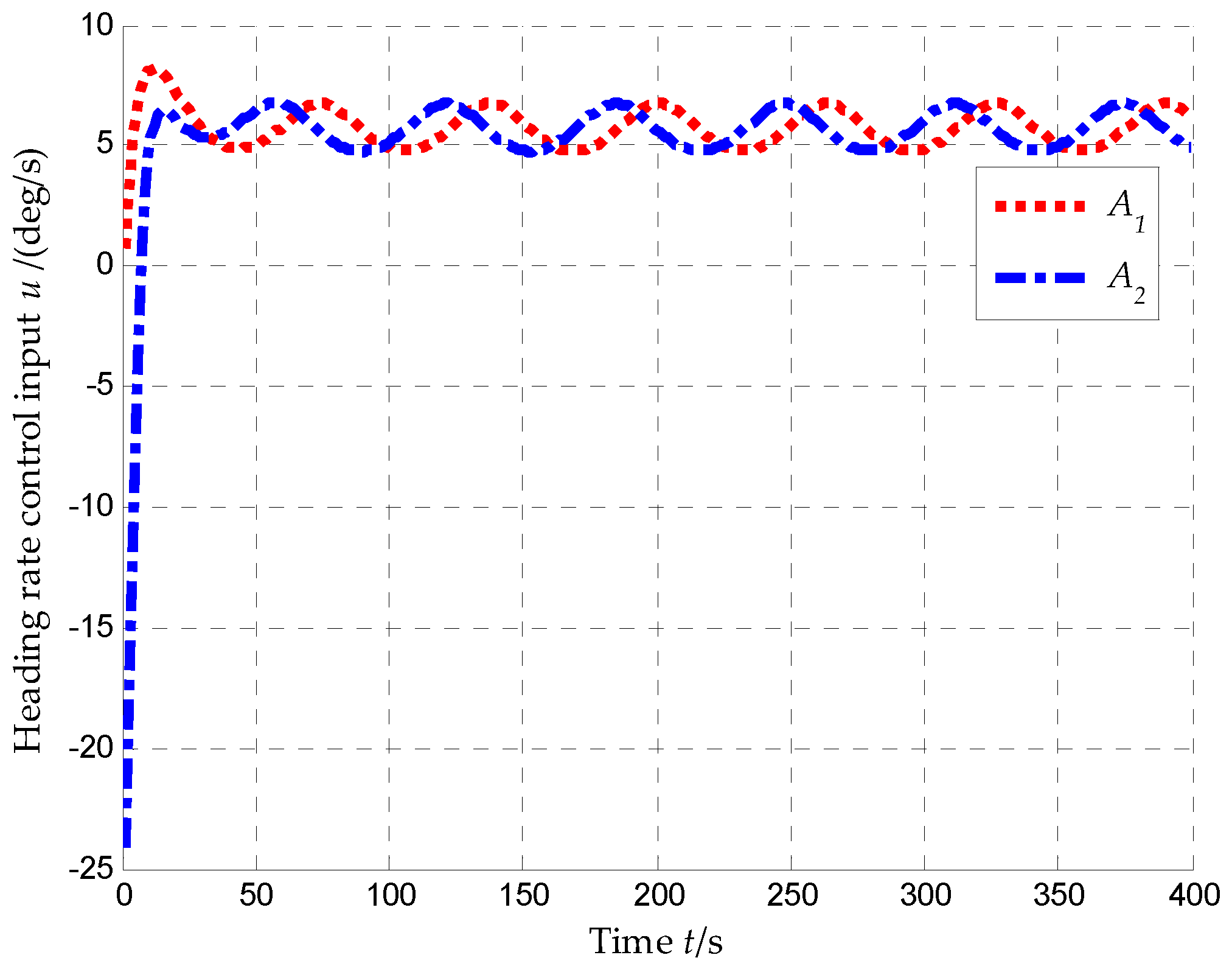
Figure 8.
Heading rate control inputs of UAVs, , (scenario 1).
Figure 8.
Heading rate control inputs of UAVs, , (scenario 1).
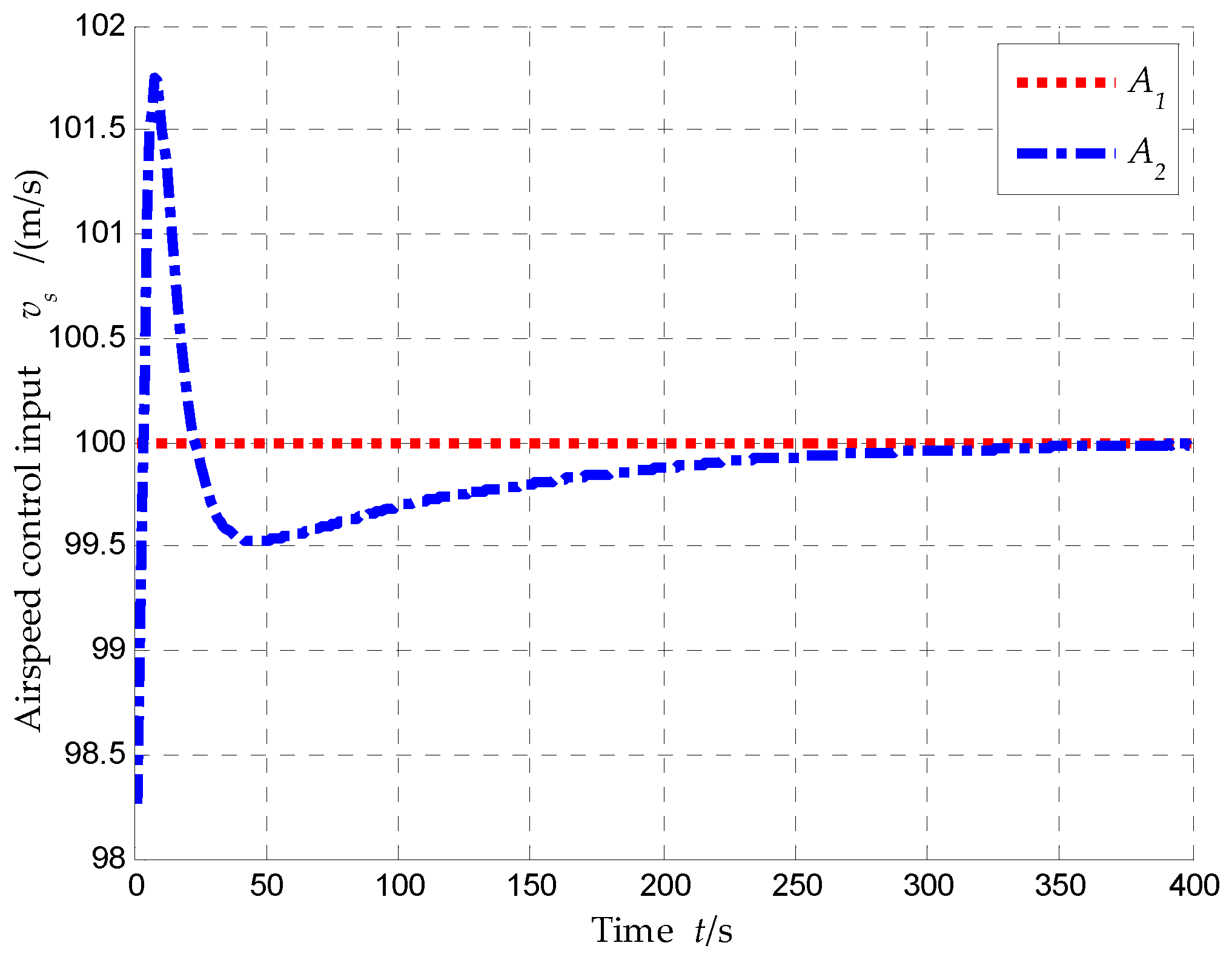
Figure 9.
Airspeed control inputs of UAVs, , (scenario 1).
Figure 9.
Airspeed control inputs of UAVs, , (scenario 1).
Figure 10.
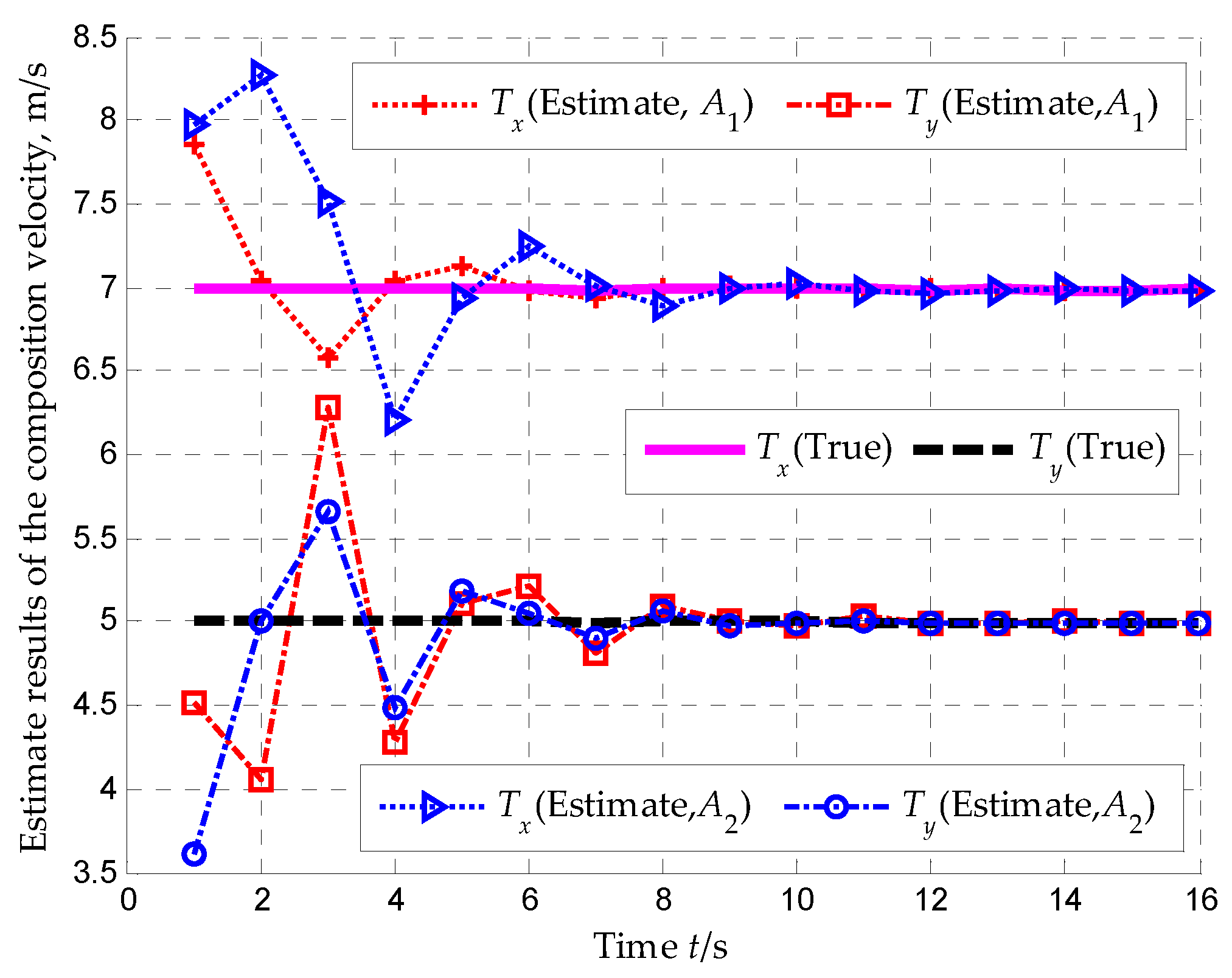
Estimate results of the composition velocity, , (scenario 1).
Figure 10.
Estimate results of the composition velocity, , (scenario 1).
Figure 11.
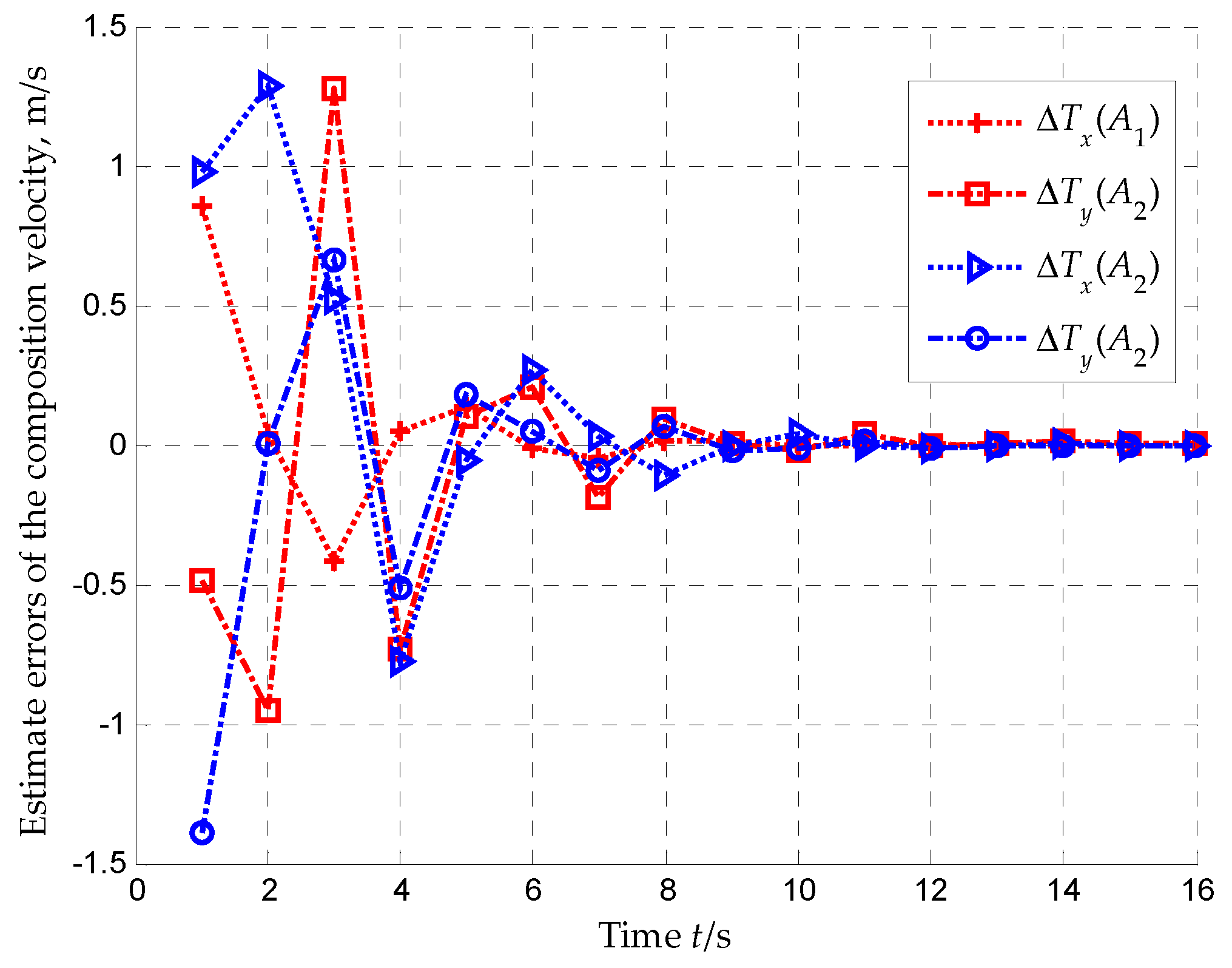
Estimate errors of the composition velocity, , (scenario 1).
Figure 11.
Estimate errors of the composition velocity, , (scenario 1).
Figure 12.
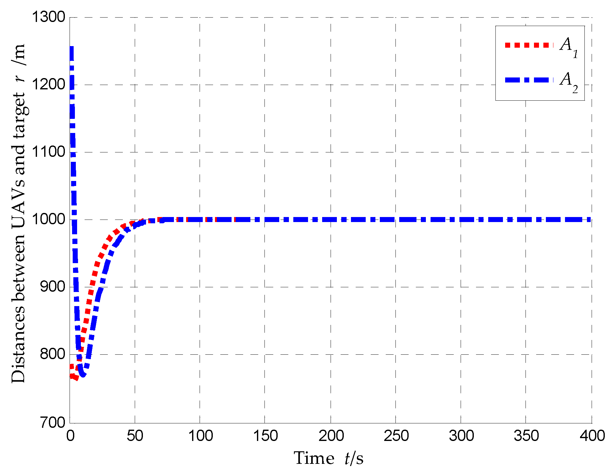
Distances between UAVs and target, , (scenario 1).
Figure 12.
Distances between UAVs and target, , (scenario 1).
Figure 13.
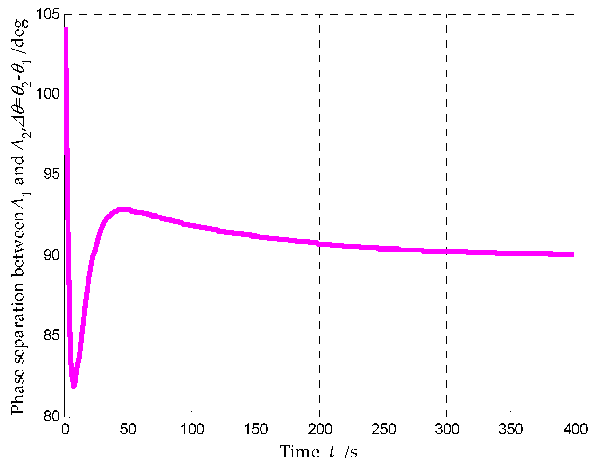
Phase separation between and , , (scenario 1).
Figure 13.
Phase separation between and , , (scenario 1).
Figure 14.
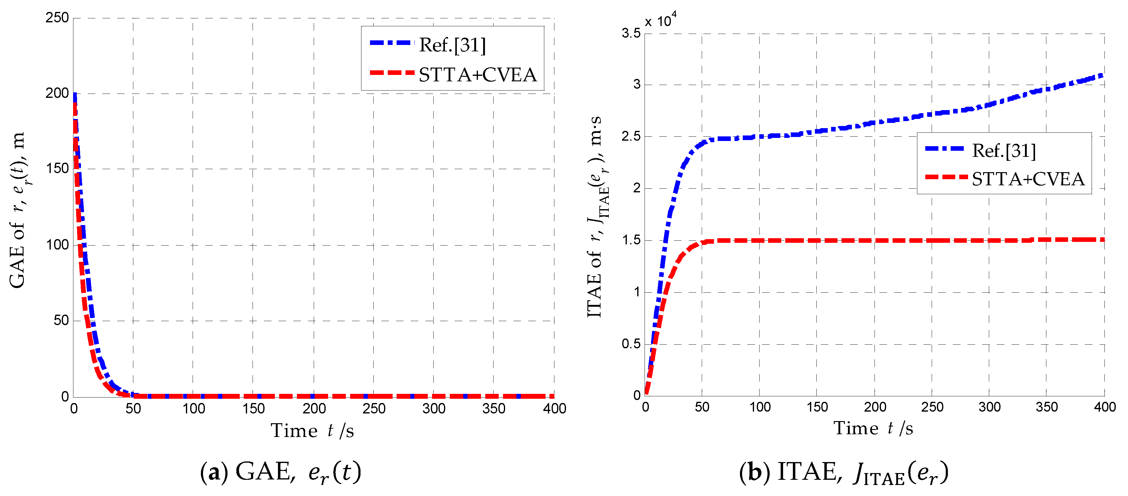
Performance of relative distance regulation (scenario 2). (a) Global average error of relative distance. (b) Integrated time absolute error of relative distance.
Figure 14.
Performance of relative distance regulation (scenario 2). (a) Global average error of relative distance. (b) Integrated time absolute error of relative distance.
Figure 15.
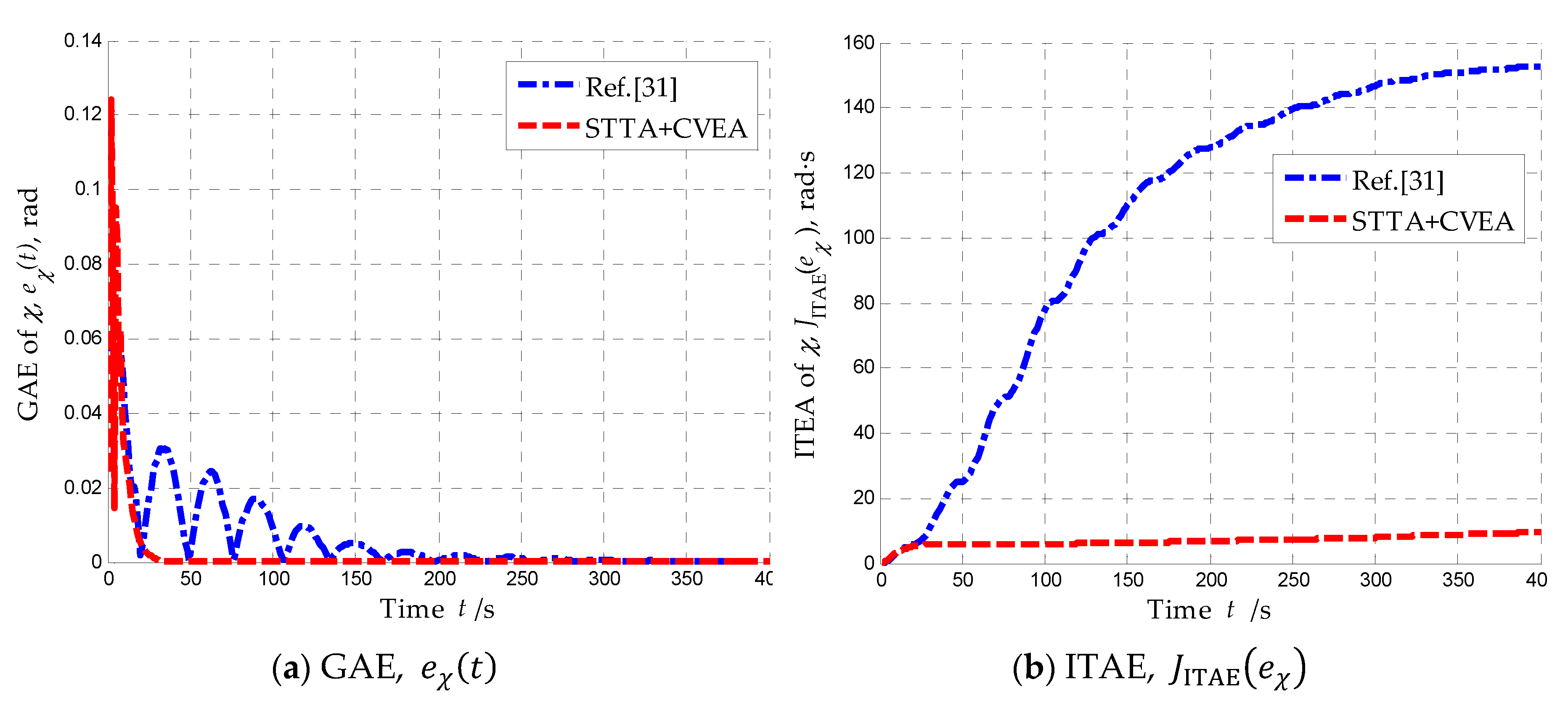
Performance of relative course tracking (scenario 2). (a) Global average error of relative course. (b) Integrated time absolute error of relative course.
Figure 15.
Performance of relative course tracking (scenario 2). (a) Global average error of relative course. (b) Integrated time absolute error of relative course.
Figure 16.
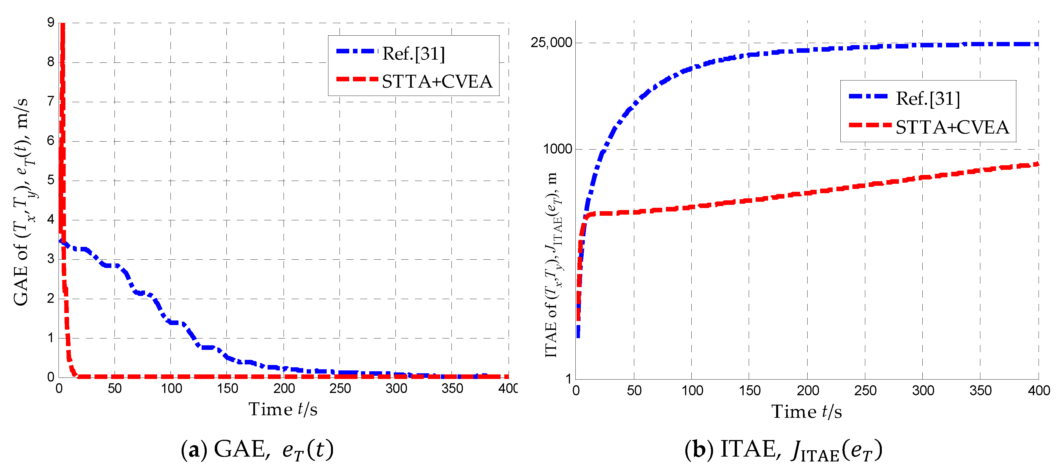
Performance of composition velocity estimation (scenario 2). (a) Global average error of composition velocity estimation. (b) Integrated time absolute error of composition velocity estimation.
Figure 16.
Performance of composition velocity estimation (scenario 2). (a) Global average error of composition velocity estimation. (b) Integrated time absolute error of composition velocity estimation.
Figure 17.
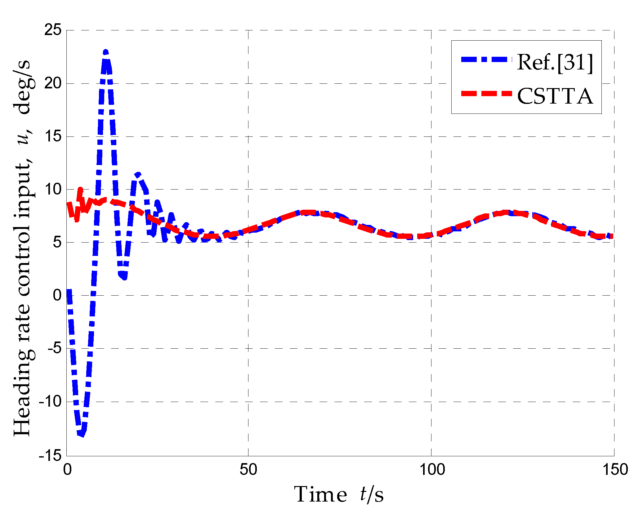
Heading rate control input of UAV, , (scenario 2).
Figure 17.
Heading rate control input of UAV, , (scenario 2).
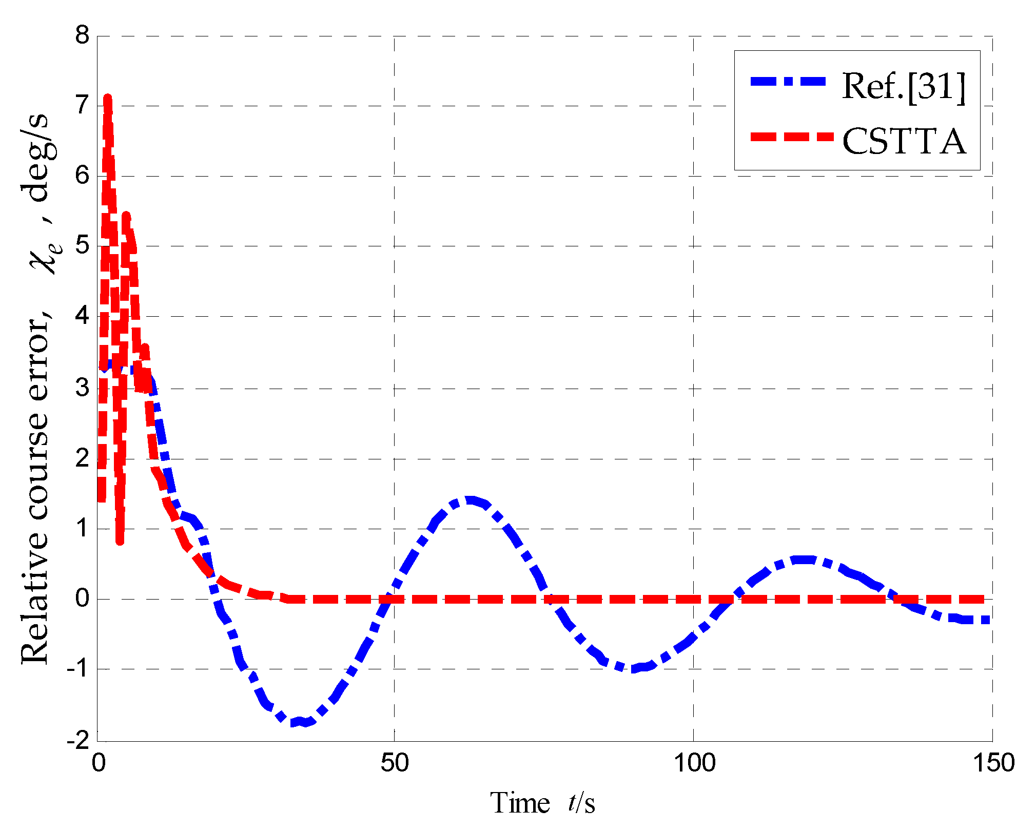
Figure 18.
Relative course error of UAV, , (scenario 2).
Figure 18.
Relative course error of UAV, , (scenario 2).
Figure 19.
Performance of intervehicle phase separation (scenario 3). (a) Global average error of phase separation. (b) Integrated time absolute error of phase separation.
Figure 19.
Performance of intervehicle phase separation (scenario 3). (a) Global average error of phase separation. (b) Integrated time absolute error of phase separation.
Table 1.
Simulation conditions (scenario 1).
Table 1.
Simulation conditions (scenario 1).
| Parameter |
Description |
Value |
|
Initial time of simulation |
0s |
|
Sampling time |
1.0s |
|
Final time of simulation |
400s |
|
Wind velocity |
(-5, -2) m/s |
|
Upper bound |
10m/s |
|
Desired standoff airspeed |
100m/s |
|
Desired standoff radius |
1000m |
Table 2.
Kinematic constraints of the UAV (scenario 1).
Table 2.
Kinematic constraints of the UAV (scenario 1).
| Parameter |
Description |
Value |
|
Allowable minimum airspeed |
60m/s |
|
Allowable maximum airspeed |
160m/s |
|
Unit increment of airspeed |
30m/s |
|
Maximum heading rate |
30deg/s |
Table 3.
The initial settings of target (scenario 1).
Table 3.
The initial settings of target (scenario 1).
| Parameter |
Description |
Value |
|
Initial position of target |
(-10, 0) m |
|
Initial velocity of target |
(2, 3) m/s |
|
Process noise covariance of target |
(0.1, 0.1) m/s2
|
Table 4.
The initial settings of UAVs (scenario 1).
Table 4.
The initial settings of UAVs (scenario 1).
|
/m |
/(m/s) |
/(deg) |
|
(700, 400) |
100 |
135 |
|
(-1200, 600) |
100 |
20 |
Table 5.
The initial settings of UAVs (scenario 2).
Table 5.
The initial settings of UAVs (scenario 2).
|
/m |
/(m/s) |
/(deg) |
|
(600, 200) |
100 |
90 |
Table 6.
Performance comparison of “STTA+CVEA” and Ref. [
31] (scenario 2).
Table 6.
Performance comparison of “STTA+CVEA” and Ref. [
31] (scenario 2).
| Control Objective |
Performance Index |
STTA+CVEA |
Ref.[31] |
Percentage/(%) |
| Relative distance regulation |
|
4.2229 |
5.9846 |
29.44 |
|
1.4436e+004 |
2.5706e+004 |
43.84 |
| Relative course tracking |
|
0.0020 |
0.0062 |
67.74 |
|
6.9507 |
106.9023 |
93.50 |
| Composition velocity estimation |
|
0.0954 |
0.8598 |
88.90 |
|
313.6534 |
1.6874e+004 |
98.14 |
Table 7.
The initial settings of UAVs (scenario 3).
Table 7.
The initial settings of UAVs (scenario 3).
|
/m |
/(m/s) |
/(deg) |
|
(600, 200) |
100 |
90 |
|
(-600, 300) |
100 |
120 |
|
(0, 800) |
100 |
-170 |
Table 8.
Performance comparison of CSTTA and Ref. [
25] (scenario 3).
Table 8.
Performance comparison of CSTTA and Ref. [
25] (scenario 3).
| Control Objective |
Performance Index |
CSTTA |
Ref. [25] |
Percentage/(%) |
| Relative distance regulation |
|
6.5996 |
10.7001 |
38.32 |
|
2.5579e+004 |
5.7246e+004 |
55.32 |
| Relative course tracking |
|
0.0090 |
0.0135 |
33.33 |
|
21.3996 |
117.3008 |
81.76 |
| Intervehicle phase separation |
|
0.3311 |
0.4273 |
22.51 |
|
8.0284e+003 |
8.4378e+003 |
4.85 |
| Composition velocity estimation |
|
0.0190 |
0.5658 |
96.64 |
|
173.0739 |
2.4136e+004 |
99.28 |
