1. Introduction
In the last few decades, the spherical mobile robot has been researched widely because it has more points of excellence from its body mechanism such as no body extremities (fully enclosed design), a statically stable structure, less friction, easy recovery from collisions and so on. These advantages, especially the stable structure and easy recovery from collision make the spherical robot land and work in the unmanned and uncertain environment as an exploration rover. [
1,
2,
3,
4,
5]
Although almost all spherical mobile robots have the same external structure, they have different types of the internal structure for driving. Cai et al. introduced a single pendulum structure, which has two operating units; one performs driving and the other controls the pendulum, [
6] and Zhao et al. proposed two pendulum mechanism. It has three operating units consisting of one driving unit and two control units for each pendulum. [
7] DeJong et al. studied the four-pendulum mechanism without a driving unit [
8] In addition, the cart-type spherical mobile robot is driven by inserting a cart inside the spherical mobile robot. The cart-type spherical mobile robot has been modified in various ways depending on the type of cart. [
9,
10,
11,
12]
Among the various types of spherical mobile robots, the single pendulum spherical mobile robot is easy to implement due to its simple structure. Therefore, many studies have been conducted on these single pendulum spherical mobile robots; Qiang et al. dealt with the dynamic trajectory tracking problem of a spherical mobile robot using a backstepping controller. [
13] Yue et al. dealt with the problem of overcoming rolling resistance using sliding mode control after deriving a dynamic model of a spherical mobile robot. [
14] Kayacan et al. proposed a study on a dynamic modeling using Euler-Lagrange and a feedback linearization control technique based on a fuzzy controller. [
15] Andani et al. estimated the angle of the pendulum through a neural network observer and proposed tracking control of the spherical mobile robot after removing the model uncertainty by a sliding mode controller. [
16]
Most of the previous studies mentioned above have dealt with the rolling motion control of spherical mobile robots. However, the important control object of spherical mobile robots is to solve the underactuation problem, which causes the degradation of the control performance and the deterioration of the stability. [
17] Studies have been conducted on hierarchical sliding mode controllers to address these under-actuated problems. [
18] The hierarchical sliding mode control method can solve the under-actuated problem by setting up a hierarchical structure using sliding surfaces and maintain robustness against uncertainty. However, there is a problem that the sliding surface for each subsystem may not converge to zero even if the sliding surface of the total system converges to zero. As a result, the anti-disturbance ability of sliding mode control might be lost. [
19,
20] Therefore, we present an alternative method to solve the under-actuated problem.
In this paper, we propose a virtual control input based nonlinear control method for the path following of an under-actuated spherical mobile robot. In order to control the uncontrollable state without an input terminal, a virtual reference input is substituted for the conventional reference input. The virtual reference input is designed at will by a designer. Therefore, if the virtual reference input is applied identically to the design of the control input, it operates as another control input for controlling the uncontrollable state. Not only the parallel motion of the X-Y plane but also the yaw of the spherical mobile robot are controlled by the proposed method. The proposed method does not require any additional control technique.
The rest of this paper is organized as follows. In section 2, A brief introduction to feedback linearization is provided. In section 3, modeling of the kinematics of a spherical mobile robot is presented. In section 4 introduces the proposed method solving the under-actuated problem of the spherical mobile robot. In section 5, simulation is performed to verify the performance of the designed controller. Finally, conclusions are drawn in section 6.
2. Preliminaries
This section describes the feedback linearization introduced in [
21]. Feedback linearization is a common approach used to control nonlinear systems. The main idea of this approach is to algebraically transform the nonlinear system dynamics into a fully or partially linearized system so that the feedback control techniques could be applied. It is different from linear approximation using Taylor series or Jacobian matrix for linear control because the stability of the whole system is guaranteed by accurate state transformation and feedback.
The idea of feedback linearization, i.e., of canceling the nonlinearities and imposing a desired linear dynamics, can be simply applied to a class of nonlinear systems described by the so-called companion form, or controllability canonical form. A system is said to be in companion form if its dynamics is represented by
where
u is the scalar control input,
x is the scalar output of interest,
is the state vector, and
and
are nonlinear functions of the states. This form is unique in the fact that, although derivatives of
x appear in this equation, no derivative of the input
u.
Note that, in state-space representation, (
1) can be written as
Using the control input (assuming
b to be non-zero)
We can cancel the nonlinearities and obtain the simple input-output relation (multiple integrator form)
Thus, the control law
with the
chosen so that the polynomial
has all its roots strictly in the left-half complex plane, leads to the exponentially stable dynamics
which implies that
. For tasks involving the tracking of a desired output
, the control law
(where is the tracking error) leads to exponential convergence of tracking errors. Note that similar results would be obtained if the scalar x was replaced by a vector and the scalar b by an invertible square matrix.
3. Description of spherical mobile robot
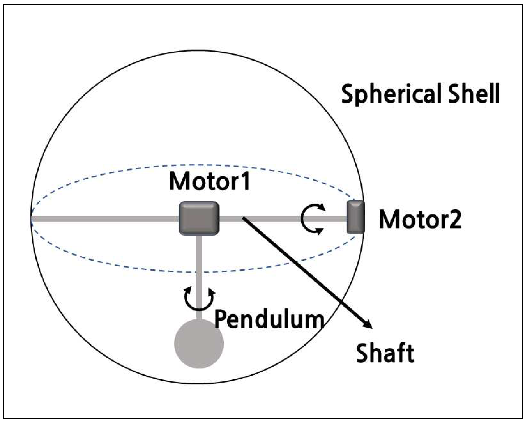
A single pendulum spherical mobile robot with two degrees of freedom pendulum is introduced as
Figure 1 shows. A shaft is placed in a straight line at the center of the spherical shell and a pendulum is installed at the center of the shaft. Motor 1 rotates the pendulum along the horizontal axis of the shaft and controls the steering of the spherical mobile robot by its rotation. Motor 2 rotates the shaft around the vertical axis and controls the driving of the spherical mobile robot.
3.1. Kinematic model
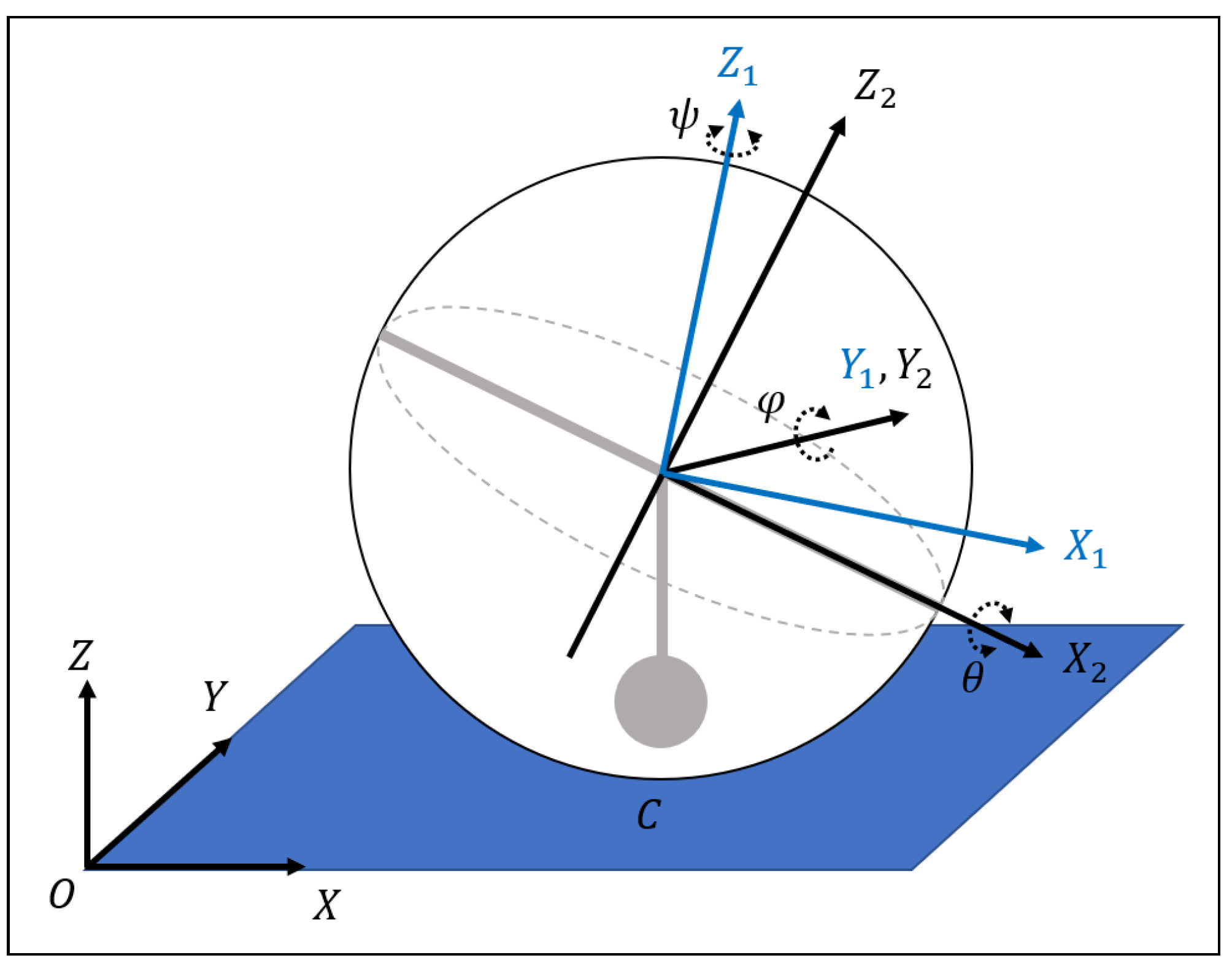
The
Figure 2 shows the rotation of spherical, where
,
and
indicate roll-pitch-yaw angles of the spherical mobile robot.
represents the reference frame {
A} and
is a body frame {
B} which can rotate by angle
about Z axis. As
rotates,
, a frame {
C} is generated. In order to derive the kinematic model, two rotation matrices should be obtained; between a frame {
A} and a frame {
B}, and between a frame {
B} and a frame {
C}. The rotation matrix between a frame {
A} and a frame {
B} is represented as follows:
The rotation matrix between a frame {
A} and a frame {
B} is described as
The angular velocity of the spherical mobile robot is written as follows:
According to the relative velocity formula, the following equation is given
where
is the velocity of the spherical mobile robot,
represents its contact point velocity with the ground surface and
shows the relative velocity of flexible links.
represents the position of the spherical center with respect to ground.
where
R is the radius of the sphere.
We assume that the spherical robot rotates without slipping. Therefore,
and the equation (
9) can be written in the following form:
Through the coordinate transformation, the velocity of the spherical mobile robot in frame {
A} is as follows:
where
because there is not any actuator around the vertical axis and as it is mentioned the robot rotates without slip so the angular velocity can be derived by the following equation.
Based on equations (
13), (
14), the kinematic model of the spherical mobile robot is derived as
Define
and
. Then equation (
15) can be rewritten as
As equation (
16) represents, the spherical mobile robot is an under actuated system. In the next section, the control technique is introduced to solve the under-actuated problem.
4. The design of controller
4.1. Controller Design
To solve the under-actuated problem, we propose the controller design method using virtual reference input.
As
Figure 3 shows, the block diagram of proposed closed-loop control system. There is no direct way to control the heading direction angle,
in the given system. In tracking control problem, a reference input is provided in general. With this point of view, we generate reference inputs especially for
and using the error dynamics derive a virtual control input for
.
The error is defined as follows:
where
,
,
are the reference input values for each state.
Remark 1. Remark The definition (17) provides decoupled inputs for each state in error dynamics. In general, an error varibles are directly defined with the state variables of systems. However, it occurs the input coupling problem in the kinematic model of spherical mobile robot. In order to solve the problem, some refine technique is required such as the coordinate transformation in (17). Through (17), input controls state X and input controls state Y as a result.
Differentiating the equation (
17) yields
where virtual reference input is defined as
.
X and
Y can be directly controlled through the two inputs of equations (
18) and (19) but
in equation (20) can‘t be controlled so it is solved through a virtual reference
Remark 2. In order to achieve path tracking of the under-actuated spherical mobile robot, an alternative input that can work as a controller is required because it must be controlled down to ψ without an input. Therefore, the virtual reference input can be arbitrarily designed like the reference input of a typical system, so it works as a control input. since it can work as another controller, it can be designed according to the Lyapunov stability theory like the conventional controller design. As a result, it can fulfill the path tracking purpose of an under-actuated spherical mobile robot.
The following theorem is proposed for path tracking of a spherical mobile robot. The proposed theorem is verified through lyapunov stability analysis.
Theorem 1. If control gain is properly designed for control input equation (21), (22) and virtual reference input equation (23) and applied to equations (18), (19), (20) it can be and ensure the tracking performance of the proposed spherical mobile robot.
where is positive real.
Proof. Consider the following Lyapunov function for stability analysis.
The equation (
24) is differentiated as follows
Substituting equations (
21), (22), (23) into equation (
25) it is presented as follows
It satisfies to ensure asymptotic stable, since is positive real □
5. Simulation
In this section, in order to verify the performance of the proposed method, a path tracking of the spherical mobile robot is considered and its simulation result is provided.
The reference path is and the initial condition of the spherical mobile robot is .
For the simulation, the parameters of the spherical mobile robots are given in
Table 1.
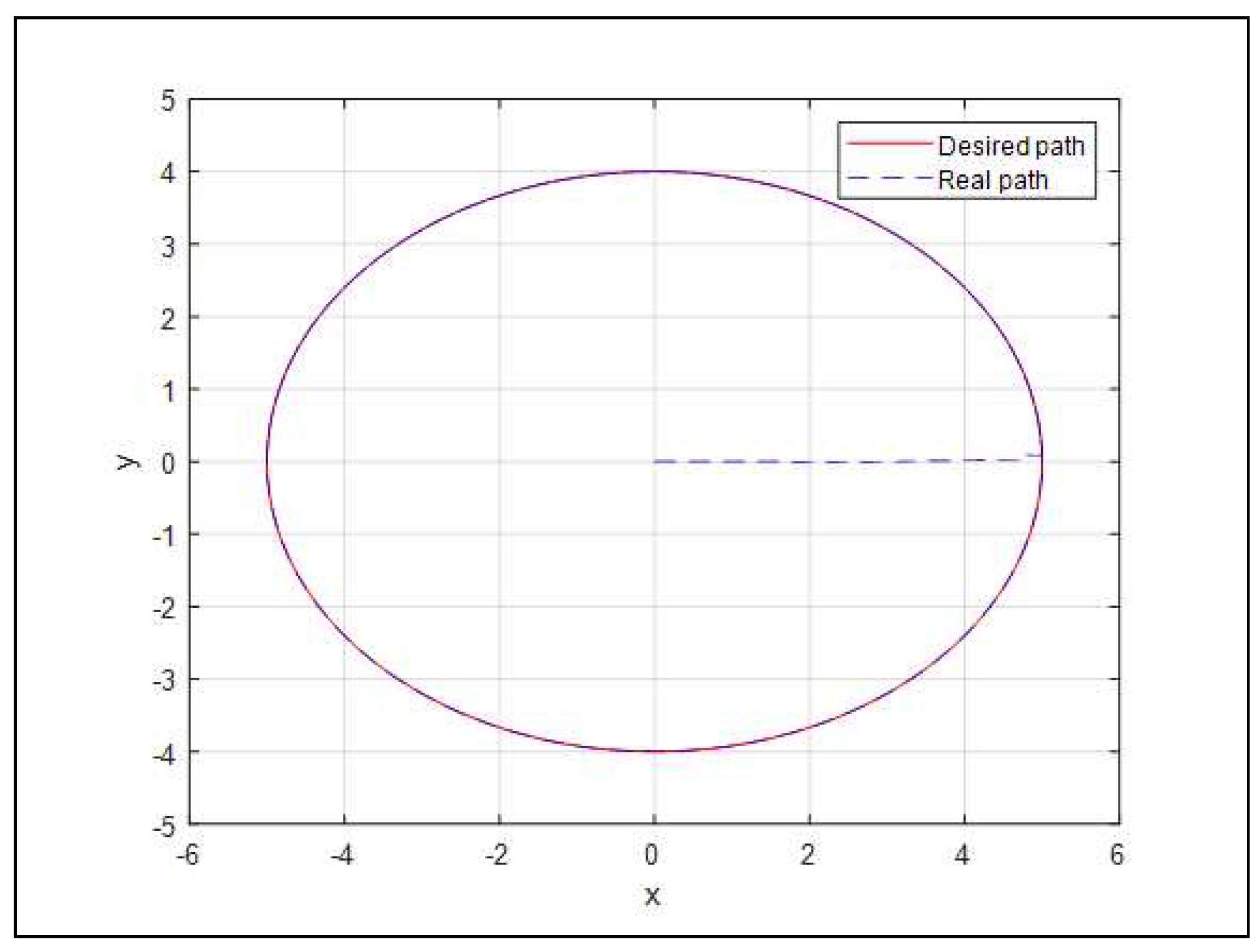
Figure 4 shows the path tracking control result in the
plane, As times goes, the spherical mobile robot departs the initial position and follows to the reference path within 0.5 seconds.
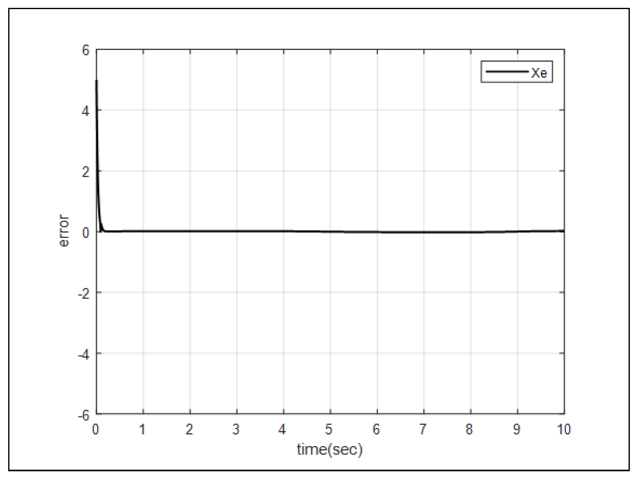
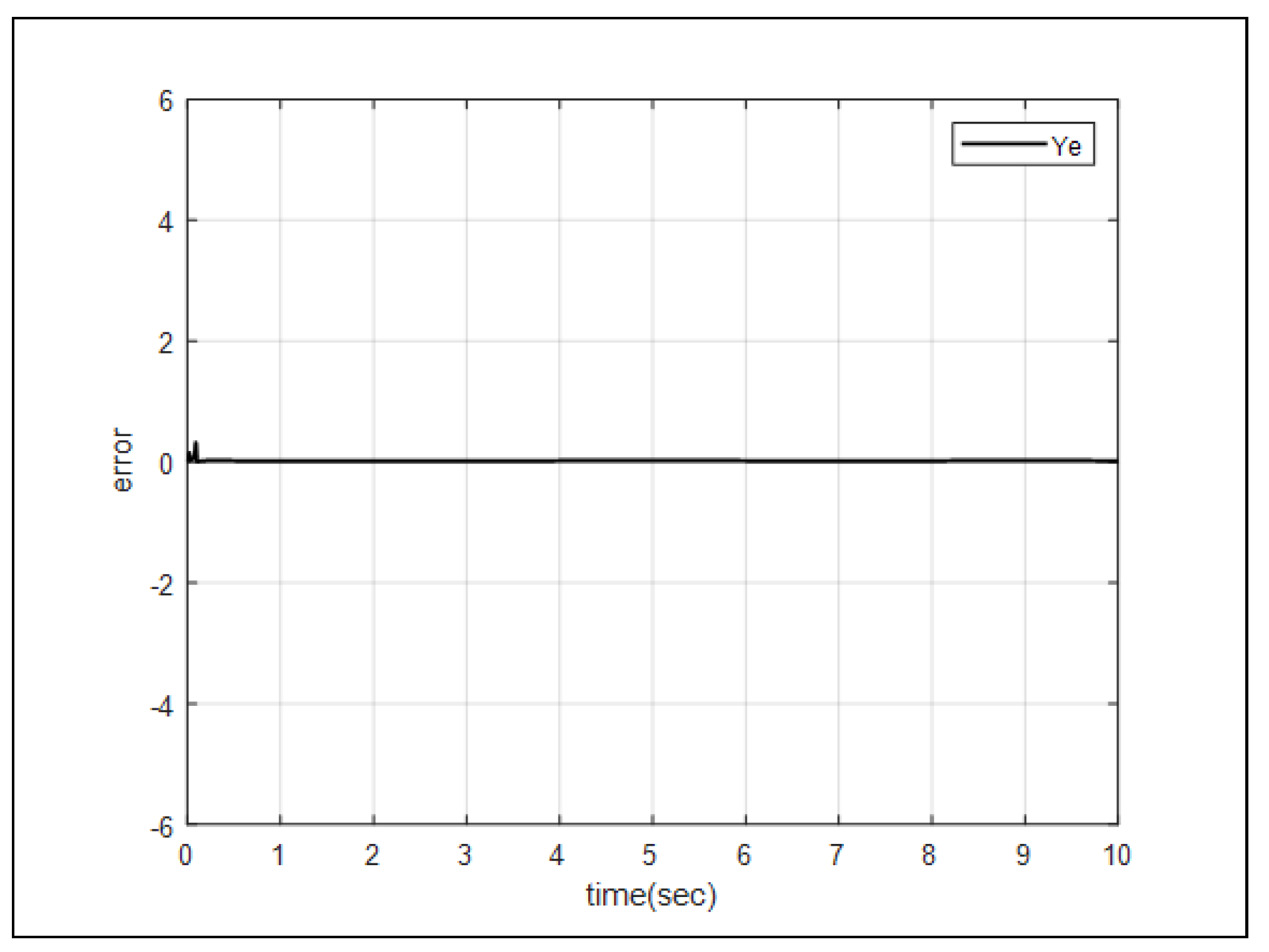
Figure 5 and
Figure 6 describe the error between the reference input
and the state
X, and the error between the reference input
and the state
Y. As figures indicate, errors converge to zero.
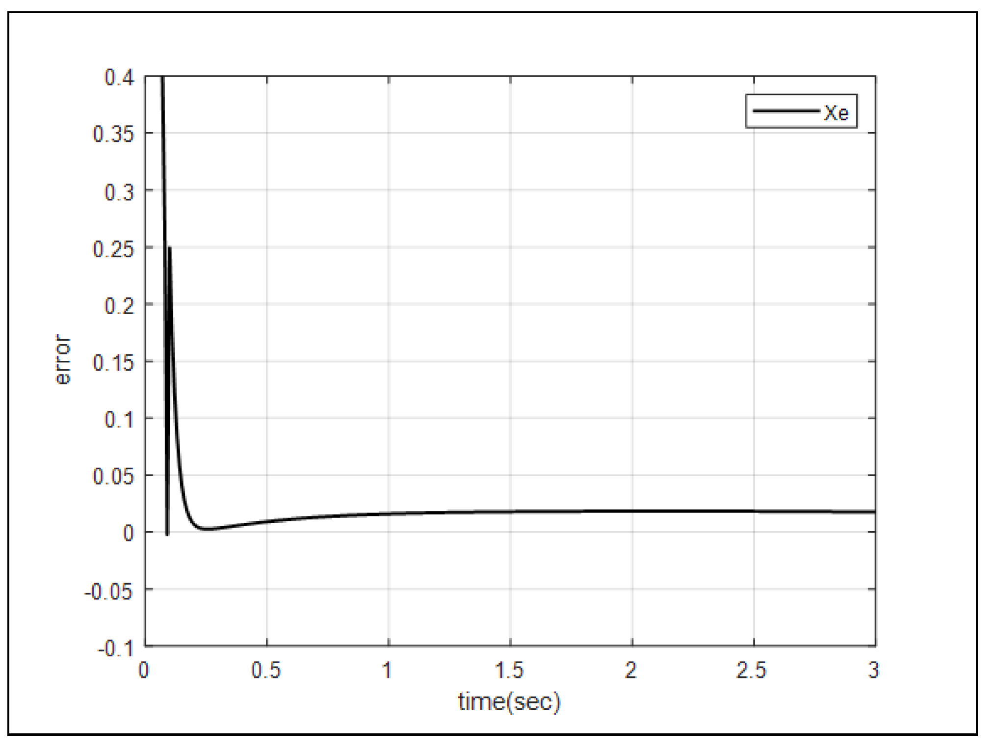
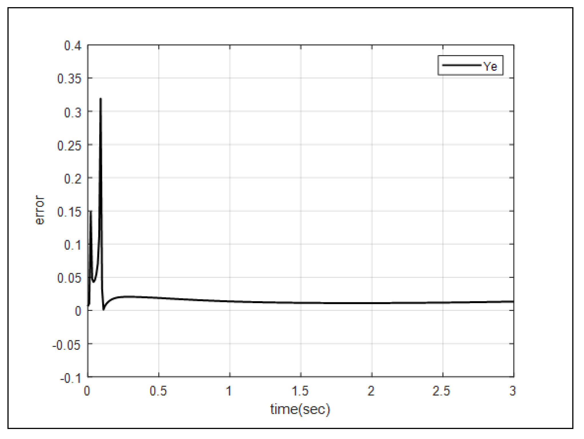
Figure 7 and
Figure 8 describe the settling time of the error between the reference input
and the state
X, and the error between the reference input
and the state
Y. The performance of the proposed control system can be verified by quickly converging the settling time of the two errors to within 0.5 seconds.
6. Conclusion
In this paer, the virtual reference input based single loop controller is proposed for the spherical mobile robot to solve its under actuated problem in the kinematic model. The virtual reference input works as a control input since it can be arbitrarily designed just like the reference input of a conventional system. It is derived by Lyapunov Stability Theory, it guaranteed the stability of the closed loop system. The proposed scheme achieved the stabilization and path following control of the under actuated spherical mobile robot without any additional control technique and the simulation results validated its performance.
References
- Michaud, F.; Caron, S. Roball, the rolling robot. Autonomous robots. 2002, 12(2), 211–222. [Google Scholar] [CrossRef]
- Bicchi, A.; Balluchi, A.; Prattichizzo, D.; Gorelli, A. Introducing the "sphericle": an experimental tested for research and teaching in nonholonomy. Proceedings of International Conference on Robotics and Automation. 1997, 3, 2620–2625. [Google Scholar]
- Armour, R. H.; Vincent, J. F. Roball, Rolling in nature and robotics: A review. Journal of Bionic Engineering. 2006, 3(4), 195–208. [Google Scholar] [CrossRef]
- Li, Z.; Canny, J. Motion of two rigid bodies with rolling constraint. IEEE Transactions on Robotics and Automation 1990, 6(1), 195–208. [Google Scholar] [CrossRef]
- Crossley, V. A. A literature review on the design of spherical rolling robots. Pittsburgh, Pa. 2006; 1–6. [Google Scholar]
- Cai, Y. , Zhan, Q.; Xi, X. Path tracking control of a spherical mobile robot. Mechanism and Machine Theory. 2012, 51, 58–73. [Google Scholar] [CrossRef]
- Zhao, B.; Li, M.; Yu, H.; Hu, H.; Sun, L. Dynamics and motion control of a two pendulums driven spherical robot. In 2010 IEEE/RSJ International Conference on Intelligent Robots and Systems, 2010; 147–153. [Google Scholar]
- DeJong, B. P.; Karadogan, E.; Yelamarthi, K.; Hasbany, J. Design and analysis of a four-pendulum omnidirectional spherical robot. Journal of Intelligent & Robotic Systems. 2017, 86, 3–15. [Google Scholar]
- Zhan, Q.; Cai, Y.; Yan, C. Design, analysis and experiments of an omni-directional spherical robot. In 2011 IEEE International Conference on Robotics and Automation. 2011, 4921–4926. [Google Scholar]
- Firlej, S. Roball, Design, construction and control of a spherical rolling robot with internal two-wheel cart. Automatyka/Automatics. 2015, 19(2), 63. [Google Scholar] [CrossRef]
- Mojabi, P. Introducing August: a novel strategy for an omnidirectional spherical rolling robot. In Proceedings 2002 IEEE International Conference on Robotics and Automation. 2002, 4, 3527–3533. [Google Scholar]
- Karavaev, Y. L.; Kilin, A. A. The dynamics and control of a spherical robot with an internal omniwheel platform. Regular and Chaotic Dynamics. 2015, 20, 134–152. [Google Scholar] [CrossRef]
- Qiang, Z.; Zengbo, L.; Yao, C. A back-stepping based trajectory tracking controller for a non-chained nonholonomic spherical robot. Chinese Journal of Aeronautics. 2008, 21(5), 472–480. [Google Scholar] [CrossRef]
- Yue, M.; Liu, B.; Wei, X.; Hu, P. Adaptive sliding-mode control of spherical robot with estimated rolling resistance. Cybernetics and Systems. 2014, 45(5), 407–417. [Google Scholar] [CrossRef]
- Kayacan, E.; Bayraktaroglu, Z. Y.; Saeys, W. Modeling and control of a spherical rolling robot: a decoupled dynamics approach. Robotica. 2015, 30(4), 671–680. [Google Scholar] [CrossRef]
- Taheri Andani, M.; Ramezani, Z.; Moazami, S.; Cao, J.; Arefi, M. M.; Zargarzadeh, H. Observer-Based sliding mode control for path tracking of a spherical robot. Complexity. 2018. [Google Scholar] [CrossRef]
- Reyhanoglu, M.; van der Schaft, A.; McClamroch, N. H.; Kolmanovsky, I. Dynamics and control of a class of underactuated mechanical systems. IEEE Transactions on automatic control. 1999, 44(9), 1663–1671. [Google Scholar] [CrossRef]
- Qian, D.; Yi, J.; Zhao, D. Hierarchical sliding mode control for a class of SIMO under-actuated systems. Control and cybernetics 2008, 37(1), 159–175. [Google Scholar]
- Bao-Li, M. Comments on" Structure design of two types of sliding-mode controllers for a class of under-actuated mechanical systems". arXiv preprint arXiv:1208.6144. 2012.
- Park, K. B. Comments on’design of a stable sliding-mode controller for a class of second-order underactuated systems’. IET control theory & applications. 2012, 8(6), 1153. [Google Scholar]
- Slotine, J. J. E.; Li, W. Applied nonlinear control. Prentice Hall 1991. [Google Scholar]
|
Disclaimer/Publisher’s Note: The statements, opinions and data contained in all publications are solely those of the individual author(s) and contributor(s) and not of MDPI and/or the editor(s). MDPI and/or the editor(s) disclaim responsibility for any injury to people or property resulting from any ideas, methods, instructions or products referred to in the content. |
© 2023 by the authors. Licensee MDPI, Basel, Switzerland. This article is an open access article distributed under the terms and conditions of the Creative Commons Attribution (CC BY) license (http://creativecommons.org/licenses/by/4.0/).
