
Submitted:
20 July 2023
Posted:
21 July 2023
You are already at the latest version
Abstract
In view of the limitations of the existing optimization method of suspender cable force, in order to improve the stress of suspender under completion state and avoid frequent adjustment of cable force and grid beam elevation during construction, a new method of cable force optimization is proposed. The article takes the longest large span arch bridge in the world, Pingnan Third Bridge, a Concrete-filled steel tube (CFST) arch bridge with a span of 575m as the engineering background combined with the finite element analysis and multi-objective optimization method. One cable force optimization method that suspender “Real-time correction during construction, in the process variable optimal and results reliable” during panel girder lifting of long span CFST arch bridges is clarified. Taking the panel girder weight and displacement during the construction as parameter variables, the displacement and unevenness of the panel girder under completion state as constraint conditions, the displacement and cable force during the hoisting construction as the objective equation, through the optimization of the objective equation, the suspender cable force and dis-placement of each hoisting section are calculated. The results show that it is feasible to introduce the optimization theory into the cable force optimization when lifting the panel girder. the segment displacement variation is minimized to meet the destination. The cable force distributed evenly under completion state of the bridge that further making sure the completion state satisfies the requirements. No repeating iteration is needed, thus avoiding cumberso me calculation, getting cable force once. With higher optimization efficiency and better effects, the method provides high value for the cable force calculation of same type bridge suspender construction and for guiding construction.
Keywords:
concrete-filled steel tube (CFST) arch bridge
; suspender cable force
; multi-objective optimization
; real-time correction
; process variables optimal
; reliable results at completion state
1. Introduction
Long span CFST arch bridges are becoming more and more preferred for its low cost, fast construction, inexpensive to maintain, reasonable force and durability(Zheng, 2020, Jielian Zheng 2018, Chen, 2007). China ranks first in constructing CFST arch bridges as around 500 bridges have been built within less than 30 years since this technology is born and 70 among the bridges are more than 200m(Zheng, 2017, Jielian Zheng 2014, Baochun Chen, 2017). The CFST bridge has a large step forward when the advanced technologies, are applied in bridge construction(Jielian Zheng 2018, Zheng, 2018). After the completion of Chongqing Wushan Yangtze River Bridge of a 460m span and that of 530-meter Sichuan Hejiang Yangtze River Bridge, both located in South-west Chin, the Pingnan Third Bridge, whose span is 575m, is under construction and set a new world record again. New requirements of construction technologies, techniques, control theories and calculation methods are needed each time when the span of large span CFST arch bridges increases.
The way to determine the initial tension of the suspender is similar to that of cable stayed bridges. In china, forward iteration method(Donghuang Yan 1999, Qing Li, 2015, Jun Yang, 2006), backward analysis method(Kegui Xin 2004), minimum bending energy method(Yue Xu, 2016, Yu Chi Sung, 2006, Liu, 2009, Wei Zhao 2016), influence matrix method(Jianmin Zhang 2005, Rucheng Xiao 1998), rigid suspender method(Xiaolin Che, 2018, Jinlong Fu 2014), as well as difference iteration method(Xuan Yang 2008) are commonly adopted. While forward iteration method needs cumbersome calculations, constrained by convergence conditions, partially non-convergent. Geometric nonlinearity, shrinkage and creep, constraints are not considered in the backward analysis method and structural internal force does not close. As for the minimum bending energy method, which takes effects to the finished bridge state, does not take the construction process into consideration, thus can only be applied into dead load cable force optimization. Influence matrix method is widely used, while it has lower accuracy and the short suspender cable force has high heterogeneity. Difference iteration method is based on the forward iteration method, merely reducing the number of convergences. By combining the difference iteration method with influence matrix, Yang Xuan(Xuan Yang 2008) achieves that the equation convergence speeds up, then decreases the calculation. Nakayama(Hirotaka Nakayama and Watada, 1995) applies the multi target optimization into the cable-stayed bridge construction control. Before the arch rib closure, Zhang Zhicheng et al.(Zhicheng Zhang 2004) think that the minimum sum of the squares of the deviation from the control point can be established as the cable force optimization objective. However, none of the methods mentioned above consider the state variable during construction. During the cable stay buckling and arch rib lifting, Hang Yu(Yu Han, 2018) and Du Hailong(Hailong Du 2019) put up with the idea of process optimal, and results controllable for calculating the cable force and arch rib deformation when assembling the arch ribs. Jie Dai (Jie Dai, 2019) suggests that the main direction of development in this field is the coupled optimization problem of reasonable bridge construction status and reasonable construction status, along with the embedded fusion of optimization algorithms and finite element programs. Yulin Zhan (Yulin Zhan, 2022) has proposed an optimization method for cable forces in irregular cable-stayed bridges based on response surface methodology and particle swarm optimization algorithm. This method enhances the rationality of the main beam's stress distribution and improves the overall linearity, thereby simplifying the cable force optimization process for irregular cable-stayed bridges. Moreover, the genetic algorithm, unit force method and B-type bar difference curve method and so on are studied for their application in cable stayed bridge cable force optimization by international scholars(A Kasuga, 1995, A M B Martins, 2015, A Baldomir 2010, Hassan, 2013, Hirotaka Nakayama and Watada, 1995, J H O Negrão, 1997, Junjun Guo, 2019, D Janjic 2003). M.A. Latif (M.A. Latif, 2019) introduced the enhanced Artificial Bee Colony algorithm (eABC) with the design variable selection being the cross-sectional dimensions of the steel plate. This approach aims to minimize the weight of the bridge. Alberto M.B. Martins (Alberto M.B. Martins, 2020) highlights the increasing application of metaheuristic algorithms, artificial neural networks (ANN), and surrogate models in the field of optimization. Wang, Z. (Wang, Z., 2021) presents a comprehensive optimization estimation method for cable forces and counterweights. By combining the minimum weighted total bending energy with counterweights, a multi-objective problem is formulated. The optimization problem for cable-stayed bridges considering counterweights is solved using the dynamic weighting coefficient method. Guo, J. (Guo, J., 2019) has obtained the optimal cable forces for curved cable-stayed bridges using a combination of simulated annealing and cubic B-spline interpolation curve method. Additionally, the differential evolution algorithm (Guo, J., 2023) has been employed to further enhance the optimization process. Wang, Z. (Wang, Z., 2023) proposes a Pareto weighting coefficient method to efficiently and cost-effectively solve a multi-objective model with the objectives of minimizing bending energy and counterweight. However, In the mentioned literature, a plethora of cable force optimization methods have been employed, aiming to obtain optimal cable forces through the establishment of various objective functions using mathematical approaches. However, there is still a lack of a unified optimization algorithm specifically applicable to large-span steel-concrete arch bridges. This leads to difficulties in comparing different optimization results and a lack of validation in practical engineering scenarios.
In this paper novel optimization is put forward on the basis of traditional arch bridge suspender cable force calculation method, Pingnan Third Bridge as the engineering objective. This paper proposes an optimization method for one-time tensioning of the suspender, which has the best process state variables and reliable results. The goal is to take the smallest increase in the cable force of the suspender and the smallest change in the displacement of the lattice beam as the objective function. The closest reasonable bridge formation condition is used as a constraint. This method is applicable to arch bridges with different construction sequences and spans, and provides a basis for linear control and cable force control during the lifting process of lattice beams.
2. Theory for New Optimization Method of Suspender Cable Force
The weight and displacement of beams during construction are taken as parameter variables, and the displacement of deck and its non-uniformity after the completion of bridge are regarded as constraint conditions. The target equation includes the displacement of deck beam and cable force increment during hoisting construction. Then the suspender cable force and displacement values of each hoisting section could be calculated through the optimization of the target equation. The specific calculation process of this optimization method of suspender cable force is presented as follows:
- Step 1: A finite element model is firstly established, of which the material properties, geometric properties, boundary conditions and external loading information should be consistent with the corresponding data in the design drawing.
- Step 2: The initial tension forces (X0) for a group of suspenders are then determined, and this group of initial tension (X0) is substituted into the finite element model in Step 1 for the process forward analysis and calculation. After obtaining the initial value vectors (dis0 and dis01), the corresponding influence matrices (A01, Am0 and Am1) could be obtained by adding ΔX0.
- Step 3: An optimization system is established, which should have objective equations, constraints and parameter variables at the same time. The optimization system includes as follows:
The objective equation is given by:
The constraint condition is then defined by:
The parameter variables are as follows:
where dis0 represents the displacement vector of control points on the bridge deck in the completed state under the action of initial tension value X0 for suspenders; dis01 represents the displacement vector of control points in the current tensioning segment under the action of initial tension value X0 for suspenders. X is the optimized cable force increment vector, and m is the real-time corrected weight of grid beam. dest is the target displacement vector of control points on the bridge deck in the bridge completion stage. A0 represents the influence matrix of suspender unit force on the displacement of control points of grid beam in the bridge completed sections; A01 represents the influence matrix of suspender unit force on the displacement of control points of grid beam in the tension sections. Am0 and Am01 represent the influence matrix of weight correction value on the displacement in the bridge completed section. delta is the allowable value of optimization convergence, that is, the difference vector between the optimization value and the target value. δij refers to the influence value of the tension unit force of the j-th suspender on the displacement of control points of grid beam in the i-th section. a and b are the weighting coefficients, satisfying the relationship a2 + b2 = 1, and the corresponding values can be adjusted according to the obtained influence matrix of bridges with different spans.
- Step 4: The target displacement vector of control point (dest) is set, generally dest = 0, which can be taken according to different bridge spans.
- Step 5: The determined parameters are substituted into the optimization equation to calculate the displacement and cable force of each control point for the current tensioning section and the final bridge completion stage.
The optimization process is shown in Figure 1.
3. Engineering Example Description
3.1. Third Pingnan Bridge
In this study, the Third Pingnan Bridge under construction with structural form of 575 m span half through concrete-filled steel tubular arch bridge is taken as the research object to explore the application of this proposed suspender cable force optimization method for this engineering project. The calculated rise-span ratio of Third Pingnan Bridge is 1/4, and the arch axis coefficient is 1.50. The radial height of the arch crown section is 8.5 m and the radial height of arch foot section is 17.0 m. The rib width is 4.2 m, and each rib has two upper and two lower ribs of Φ 1400 mm concrete filled steel tube chord, in which C70 concrete is used in the tube. The main beam is a grid steel-concrete composite structure with suspender spacing of 15.5 m. In the bridge deck system, the main bridge deck pavement adopts the high elastic and high viscosity SMA13 asphalt concrete with thick of 5 cm, the thickness of concrete pavement on the beam is 24 cm, and the thickness between beams is 15 cm. The cable suspender adopts 37 Φ 15.2 mm suspender cables with grade 1960 MPa, which are covered with polyethene (PE) sheath and epoxy sprayed steel strand with PE wrapped and extruded. There are 16 pairs of suspenders on the north and south riverbanks, and a total of 64 suspenders for the whole bridge. The layout of bridge deck is shown in Figure 2. Table 1 lists the material properties.
The assemble sequence of grid beams is as follows: (i) grid beam section between 1# suspender and 2# suspender is firstly assembled; (ii) grid beams among rib beam, column beam and beam end section are then installed; and (iii) after the first system conversion, 3# suspender tension and corresponding grid beam installation are carried out. In this way, the grid beams are installed symmetrically from the north and south riverbanks to the middle of the span, and the suspenders are tensioned correspondingly until the closure. Finally, bridge deck, sidewalk slab and the second phase pavement shall be constructed.
3.2. Modeling Simulation of Third Pingnan Bridge
In this study, Midas Civil 2019 is used for modeling to simulate the real construction process of Third Pingnan Bridge, which include arch rib hoisting, concrete filled steel tubular pouring, bridge deck grid beam hoisting, bridge deck construction, the second phase pavement and 10-year shrinkage and creep. The arch foot is hinge joint before the installation of No. 6 cross brace, and then converted as consolidation form after the installation of No. 6 arch rib cross brace and sealant. The beam end should be hinged during the hoisting of bridge deck grid beam, in which the arch rib and bridge deck beam are simulated by beam element, suspender and carriageway slab are simulated by truss element and slab element, respectively. It should be noted that in order to ensure that the bending moments at the grid beam and suspender joints are small, the corner constraint at the element joints can be released first, and then converted to the consolidation state. Considering the influence of structural dead weight, suspender cable force and the second phase load, since the carriageway slab is cast-in-situ concrete, the surface load shall be added to the bridge deck beam element firstly, and then the bridge deck element would be activated to simulate the process of stiffness formation. Other parameters in this construction process model adopt the design values, such as elastic modulus, bulk density, section size and other so on. The model diagram after the completion of bridge is shown in Figure 3.
4. Optimization Analysis of Suspender Cable Force
4.1. Analysis of Allowable Value (Delta) and Optimization Dispersion (Favor) of Optimization Convergence
Based on the above equation (7), the influence matrix A0 could be obtained through finite element analysis, in which the unit force is 10 kN and the unit is mm, as follows:
A01 is the lower triangular matrix of A0, which is not listed here. Theoretically, the proposed optimization method of suspender cable force can achieve the process optimization of real-time deviation and correction according to different actual hoisting weights. In this engineering example, the value m = [1,1,1…1]T, that is, the design weight is taken in each hoisting stage.
Before the optimization of suspender cable force, it is found that there is no inflection point in the curves of allowable value (delta) and optimization dispersion (favor) by analyzing the relationship curve between the delta value and the favor value. However, the slope of the delta - favor curve in the range of 0 ~ 10 mm is larger. Therefore, samples at the delta value of 0 mm, 5 mm and 10 mm are selected for further comparative analysis to determine the delta value of the optimization. Through comparison, it can be realized that the optimization effects are good when delta = 5 mm and delta = 10 mm. The relationship curve between the delta value and the favor value is shown in Figure 4.
Figure 5, Figure 6 and Figure 7 plot the relationship curves of optimized initial tension value for suspenders, suspender cable force, displacement of control points of grid beam in the tension sections and delta values. From Figure 5, Figure 6 and Figure 7, it can be seen that with the decrease of the allowable value (delta) of optimization convergence, the initial tension of 3# suspender, 15# suspender and 16# suspender deviate greatly from the average value, and the cable force of 2# suspender, 14# suspender and 16# suspender after the completion of the bridge also deviate greatly from the average value. When delta = 0 mm, the initial tension value of 3# suspender is 418 kN, which is 60 kN less than the initial tension value when delta = 5 mm. The main reason lies that the target displacement of bridge deck beam after the completion of bridge is limited by constraints, which determines the displacement of grid beams in the current hoisting section within a certain range. When the installed beam section is in place, the displacement difference between the i-th and j-th nodes will lead to the inclination of the beam body. At the same time, the next beam section is tangent assembly, that is, the preload of the front section will affect the positioning elevation of the rear section. The greater the inclination angle of the beam body in the front section, the greater the displacement of the beam body in the rear section. However, this displacement of the beam body would be limited by constraints. Thus, the suspender cable force in the rear section will become smaller, and the suspender in the front section will also share more beam weight, leading to a larger cable force. This also explains why the cable force of 3# suspender and 16# suspender in the tensioning section will be smaller when delta = 0, and in the meantime, the cable force of 2# suspender and 15# suspender is larger. The displacement curves of grid beams in the current hoisting section corresponding to different delta values have little difference. Considering that the uniformity difference of the suspender cable force and the delta value should be not too large for 1#~16# suspenders in the sections of hoisting and the completion of bridge, the convergence condition for this optimization is that delta = 5 mm.
4.2. Optimization Effects of Suspender Cable Force
Based on the theory for new optimization method of suspender cable force in the second section, a set of suspender cable forces could be obtained through optimization, and the displacement of control points of grid beam can be also obtained through the forward analysis. The calculation results of suspender cable force are shown in Table 2 and Figure 8, the displacement results of grid beam at the hoisting points are shown in Table 3 and Figure 9, and the arch rib displacement results at the hoisting points are shown in Table 4 and Figure 10.
From Table 2, Table 3 and Table 4 and Figure 8, Figure 9 and Figure 10, it can be seen that the final optimization target (delta = 5 mm) is feasible. During the period from hoisting to closure, the differences between the maximum and minimum for cable forces of 3# suspender ~15# suspender are within the range of (258 ± 2) kN, which occurs at the moments of grid beam hoisting in the rear section. The standard deviations of displacement values of 1# suspender ~ 10# suspender are (15 ± 2) mm, and those of 11# suspender ~ 16# suspender are (35 ± 9) mm. The optimized suspender cable force changes smoothly in the whole construction process, and the subsequent construction stage has the least impact on the displacement of the completed construction section, which achieves a very good optimization effect.
4.3. Verification of Optimization Method of Suspender Cable Force
In order to verify the feasibility of the proposed optimization method of suspender cable force, the minimum bending energy method was adopted to calculate the suspender cable force after the completion of bridge, and the suspender cable force results obtained by the proposed method and minimum bending energy method were compared and analyzed. The minimum bending energy method takes the structural bending residual energy as the objective function to optimize the suspender cable force after the completion of bridge, which is one of the commonly used calculation methods for the suspender cable force after the completion of bridge. However, the minimum bending energy method is only suitable for cable force adjustment under dead load. The comparison results suspender cable forces after the completion of bridge by the proposed method and minimum bending energy method are shown in Figure 11, and the comparison results of bearing reaction are listed in Table 5.
According to the above comparison results, it can be seen that the calculation results by the proposed method and minimum bending energy method are very close, but the suspender cable force optimized by the proposed method is more uniform. The proposed optimization method takes the construction process into account, and could obtain the suspender cable force and displacement of grid beam in the current tensioning section, which can be used to guide construction. This proposed optimization method can ensure that the displacement of grid beam changes little during the construction process, and the bridge alignment after the completion of bridge meets the control requirements. It can be seen from Table 5 that there is a slight deviation in the external force distribution of the bridge deck system calculated by these two methods. The support reaction force calculated by the proposed optimization method is too large, while the suspender cable force is too small, and the resultant force remains unchanged. This is mainly because the construction sequence, shrinkage and creep effects are considered in this method, and some loads are transferred from the suspender to the column and cross beam between ribs during the construction process are considered in the proposed optimization method, some loads are caused by the transfer of suspenders to columns and cross beams between ribs during the construction process. The above calculations are based on the design weight. When the weight of the grid beam is 1.05 times of the design value, the difference of the pre lift value of the grid beam in the hoisting section calculated by the proposed optimization method would be within 5 mm, the initial tension force for suspenders increases by 5%. And the increase of the grid beam weight has little impact on its displacement, and the suspender cable force will change accordingly. When the actual weight of the grid beam deviates from the theory values, the m values can be corrected in the optimization system to reanalyze the displacement and suspender cable force in the next hoisting section, so as to realize dynamic deviation correction. The optimization of suspender cable force in the construction of bridge deck system of concrete-filled steel tubular arch bridge is feasible, and the optimization effect is good. The results can be optimized at one time without repeated iterative calculations, so that the cable would not be adjusted in the process. At the same time, it ensures that the minimum displacement change of grid beam and cable force during the construction process. According to the measured values, the parameters can be also corrected and reoptimized in time to ensure that the completed bridge state could meet the design requirements.
5. Conclusions
Zheng dulian [1] mentioned that the ratio of concrete-filled steel tubular arch bridge to steel arch bridge has good mechanical performance; Compared with the cable supported bridge, stiffness is larger; It has low temperature sensitivity and good seismic performance; Its advantages are obvious. As a branch of arch bridge, the rapid increase of the number and span in China and even the world is a miracle in the bridge industry. In the future, steel tube arch bridge must develop towards larger span, more design innovation and new construction technology. As an important part of its structure, suspenders need more and better cable force optimization methods to guide the construction. Taking Pingnan third bridge as the engineering background, an efficient, accurate and real-time deviation correction method for suspender cable force optimization is explored. The following conclusions are drawn:
(1) In this paper, a new method of optimizing suspender cable force is proposed, which can minimize the increment of lattice beam displacement and target value difference in the construction process; The subsequent tensioning section has the least impact on the displacement of the constructed section, the standard deviation of the displacement of 1# suspender ~ 10# suspender is 15mm ± 2mm, and the standard deviation of the displacement of 11# suspender ~ 16# suspender is 35mm ± 9mm; The cable force of the completed bridge is uniform, the standard deviation of the suspender cable force is only 43kN, and the difference between the maximum cable force and the minimum cable force is 203kN; The alignment of the completed bridge converges to the target value, and the displacement is within 5mm, and the calculation result is reliable.
(2) The bridge deck system construction of concrete-filled steel tubular arch bridge with different span and construction sequence is calculated quickly, which has strong practicability and wide application range.
(3) Avoid the problems of concrete shrinkage, creep and structural geometric nonlinearity that cannot be considered by the traditional reverse demolition method, which is simple and practical in practical implementation; Compared with the forward iteration method, it does not need to calculate repeatedly after knowing the cable force after completion of the bridge; Compared with the minimum bending energy method, it considers the construction process, the calculation condition is closer to the actual situation, and can more truly simulate the load distribution of bridge deck system.
(4) In the actual bridge hoisting construction, through the real-time correction of design parameters and system re optimization, the process deviation correction can be realized, so as to ensure that the completed bridge state meets the requirements.
The strategy of internal force matrix method is a commonly used structural optimization technique. However, for complex structures, the process of solving using the method involves extensive matrix operations, requiring high computational power and time. In this study, we have taken into account the characteristics of actual engineering and selected a few key points to reduce the order of the influencing matrix, thereby further reducing computational costs and achieving a multi-objective tension optimization program. On the other hand, the strategy of internal force matrix method can only optimize static structures, and further research is needed regarding its applicability to dynamic structures and material performance.
Author Contributions
Conceptu-alization, M.Y. and X.Y.; methodology, M.Y.; formal analysis, N.D., T.H., L.W. and H.W.; investigation, N.D. and T.H.; data curation, X.Y.; writing—original draft preparation, M.Y.; writing—review and editing, X.Y.; funding acquisition, M.Y. All authors have read and agreed to the published version of the manuscript.
Funding
This study was partly sponsored by following Fund Programs: (1)Nanning City "Yongjiang Project" funded project (2018-01-04)
Data Availability Statement
The testing and analysis data used to support the findings of this study are included within the article.
Conflicts of Interest
We declare that there is no conflict of interest regarding the publication of this paper.
References
- Zheng, J. Innovative Technology for 500-Meter Scale CFST Arch Bridge Construction; Shanghai Science and Technology Press: Shanghai, China, 2020. [Google Scholar]
- Zheng, J. Quality and Risk: Concrete Filled Steel Tubular Arch Bridge. China Highw. 2018, 22, 40. [Google Scholar]
- Chen, B. CFST Arch Bridge; People’s Communications Press: Beijing, China, 2007. [Google Scholar]
- Zheng, J. Development and prospect of long-span arch bridge. China Highw. 2017, 13, 40–42. [Google Scholar]
- Zheng, J.; Wang, J.; Mou, T.; Fenh, Z.; Han, Y.; Qin, D. Feasibility Research on Design and Construction of 700 m CFST Arch Bridge. China Eng. Sci. 2014, 16, 5. [Google Scholar]
- Chen, B.; Zheng, J.; Zhou, J. pplication status and Prospect of CFST arch bridge in China. J. Civ. Eng. 2017, 50, 12. [Google Scholar]
- Zheng, J.; Wang, J. Concrete-Filled Steel Tube Arch Bridge in China. Engineering 2018, 4, 13. [Google Scholar] [CrossRef]
- Yan, D. Iterative method for determining the reasonable construction state of cable-stayed bridges. China J. Highw. Transp. 1999, 12, 6. [Google Scholar]
- Li, Q.; Zhao, Z.; Jie, L. Application of iterative method in construction control of suspender of tie-down tied arch bridge. China Foreign Highw. 2015, 35, 4. [Google Scholar]
- Yang, J.; Shen, C.; Sheng, J. Summarizing the Methods of Determination of Rational Completion Status of Cable-Stayed Bridges. Eng. Sci. 2006, 4, 9. [Google Scholar]
- Xin, K. Nonlinear backward analysis of large span cable-stayed bridge construction. Eng. Mech. 2004, 5, 31–35. [Google Scholar]
- Xu, Y.; Zhan, B.; Li, Y. An Optimum Calculation Method of Cable Force of CFST Arch Bridge in Inclined Cable Hoisting Construction. Highw. Transp. Sci. Technol. 2016, 33, 7. [Google Scholar]
- Sung, Y.-C.; Chang, D.-W.; Teo, E.-H. Optimum post-tensioning cable forces of Mau-Lo Hsi cable-stayed bridge. Eng. Struct. 2006, 28, 1407–1417. [Google Scholar] [CrossRef]
- Liu, Z. Determination of the optimal hanger for tied-arch bridges based on energy methods. Eng. Mech. 2009, 26, 6. [Google Scholar]
- Zhao, W.; Zhen, J.; Lu, S. Optimization Analysis of suspender tension in super long-span tied steel arch bridge at completion state. J. China Foreign Highw. 2016, 36, 6. [Google Scholar]
- Zhang, J.; Zheng, Y.; Xiao, R. Calculation method for optimizing the installation process of concrete-filled steel tube arch bridge. J. China Highw. 2005, 18, 40–44. [Google Scholar]
- Xiao, R.; Xiang, H. Influence matrix method of tension optimization for cable-stayed bridges. J. Tongji Univ. (Nat. Sci. Ed.) 1998, 26, 6. [Google Scholar]
- Che, X.; Du, B.; Zhang, X. Comparative Analysis of Methods for Determining the Suspension Cable Force of the Reinforced Concrete Tied Arch Bridge. Constr. Technol. 2018, 47, 4. [Google Scholar]
- Fu, J.; Huang, T. Applicability analysis of Optimum Methods for hanger forces of rigid tied-arch bridges at completion stage. J. Railw. Sci. Eng. 2014, 11, 8. [Google Scholar]
- Yang, X.; Zhou, S. Method to determine construction cable tension force of cable-stayed bridge. J. Chongqing Jiaotong Univ. (Nat. Sci.) 2008, 27, 5. [Google Scholar]
- Nakayama, H.; Kaneshige, K.; Takemoto, S.; Watada, Y. An application of a multi-objective programming technique to construction accuracy control of cable-stayed bridges. Eur. J. Oper. Res. 1995, 87, 731–738. [Google Scholar] [CrossRef]
- Zhang, Z.; Wang, Y. Optimization of stayed-buckle cable forces during adjustment of alignment on long span arch bridges. Eng. Mech. 2004, 21, 6. [Google Scholar]
- Han, Y.; Qin, D.; Zheng, J. Optimal calculation method for CFST arch bridge during cable-stayed buckle construction. Highway 2018, 63, 5. [Google Scholar]
- Du, H.; Qin, D.; Luo, X. Construction control of super-long-span arch bridges. Highway 2019, 6, 103–107. [Google Scholar]
- Jie, D.; Feng, J.; Qin, F.; Jin, D.; Cheng, Y. Review on Cable Force Optimization Method for Cable-stayed Bridge in Completed Bridge State. China J. Highw. Transp. 2019, 32, 5. [Google Scholar]
- Zhan, Y.; Hou, Z.; Shao, J. Cable Force Optimization of Irregular Cable-Stayed Bridge Based on Response Surface Method and ParticleS warm Optimization Algorithm. Bridge Constr. 2022, 52, 3. [Google Scholar]
- Kasuga, A.; Arai, H.; Breen, J.E.; Furukawa, K. Optimum cable-force adjustments in concrete cable-stayed bridges. J. Struct. Eng. 1995, 121, 685–694. [Google Scholar] [CrossRef]
- Martins, A.; Simões, L.; Negrão, J. Optimization of cable forces on concrete cable-stayed bridges including geometrical nonlinearities. Comput. Struct. 2015, 155, 18–27. [Google Scholar] [CrossRef]
- Baldomir, A.; Hernandez, S.; Nieto, F.; Jurado, J.A. Cable optimization of a long span cable stayed bridge in La Coruña (Spain). Adv. Eng. Softw. 2010, 41, 8. [Google Scholar] [CrossRef]
- Hassan, M. Optimization of stay cables in cable-stayed bridges using finite element, genetic algorithm, and B-spline combined technique. Eng. Struct. 2013, 49, 643–654. [Google Scholar] [CrossRef]
- Negrão, J.H.O.; Simões, L.M.C. Optimization of cable-stayed bridges with three-dimensional modelling. Comput. Struct. 1997, 28, 18. [Google Scholar] [CrossRef]
- Guo, J.; Yuan, W.; Dang, X.; Alam, M.S. Cable force optimization of a curved cable-stayed bridge with combined simulated annealing method and cubic B-Spline interpolation curves. Eng. Struct. 2019, 201, 109813. [Google Scholar] [CrossRef]
- Janjic, D.; Pircher, M.; Pircher, H. Optimization of Cable Tensioning in Cable-Stayed Bridges. J. Bridg. Eng. ASCE 2003, 8, 131–137. [Google Scholar] [CrossRef]
- Latif, M.; Saka, M. Optimum design of tied-arch bridges under code requirements using enhanced artificial bee colony algorithm. Adv. Eng. Softw. 2019, 135, 102685. [Google Scholar] [CrossRef]
- Martins, A.M.; Simões, L.M.; Negrão, J.H. Optimization of cable-stayed bridges: A literature survey. Adv. Eng. Softw. 2020, 149, 102829. [Google Scholar] [CrossRef]
- Wang, Z.; Zhang, N.; Du, X.; Wang, S.; Sun, Q. Multiobjective Optimization of Cable Forces and Counterweights for Universal Cable-Stayed Bridges. J. Adv. Transp. 2021, 2021, 6615746. [Google Scholar] [CrossRef]
- Guo, J., Yuan, W., Dang, X., et al. Cable force optimization of a curved cable-stayed bridge with combined simulated annealing method and cubic B-Spline interpolation curves. Eng Struct 2019, 201, 109813. [CrossRef]
- Guo, J.; Guan, Z. Optimization of the cable forces of completed cable-stayed bridges with differential evolution method. Structures 2023, 47, 1416–1427. [Google Scholar] [CrossRef]
- Wang, Z., Zhang, N., Cheng, Q. Multi-objective optimization-based reasonable finished state in long-span cable-stayed bridge considering counterweights. Structures 2023, 51, 1497–1506. [CrossRef]
Figure 1.
The optimization process of suspender cable force in this study.
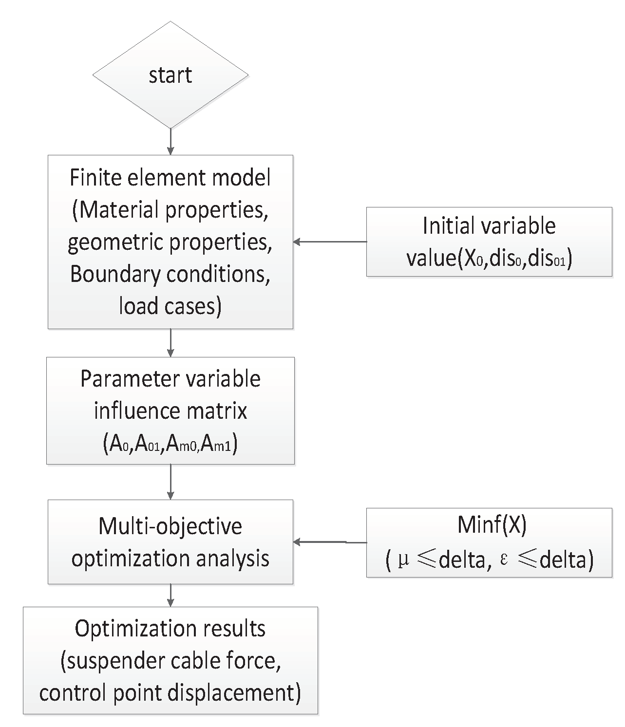
Figure 2.
General layout of CFST arch bridge-The Third Pingnan Bridge (unit: cm): (a) Description of what is contained in the first panel; (b) Description of what is contained in the second panel.
Figure 2.
General layout of CFST arch bridge-The Third Pingnan Bridge (unit: cm): (a) Description of what is contained in the first panel; (b) Description of what is contained in the second panel.
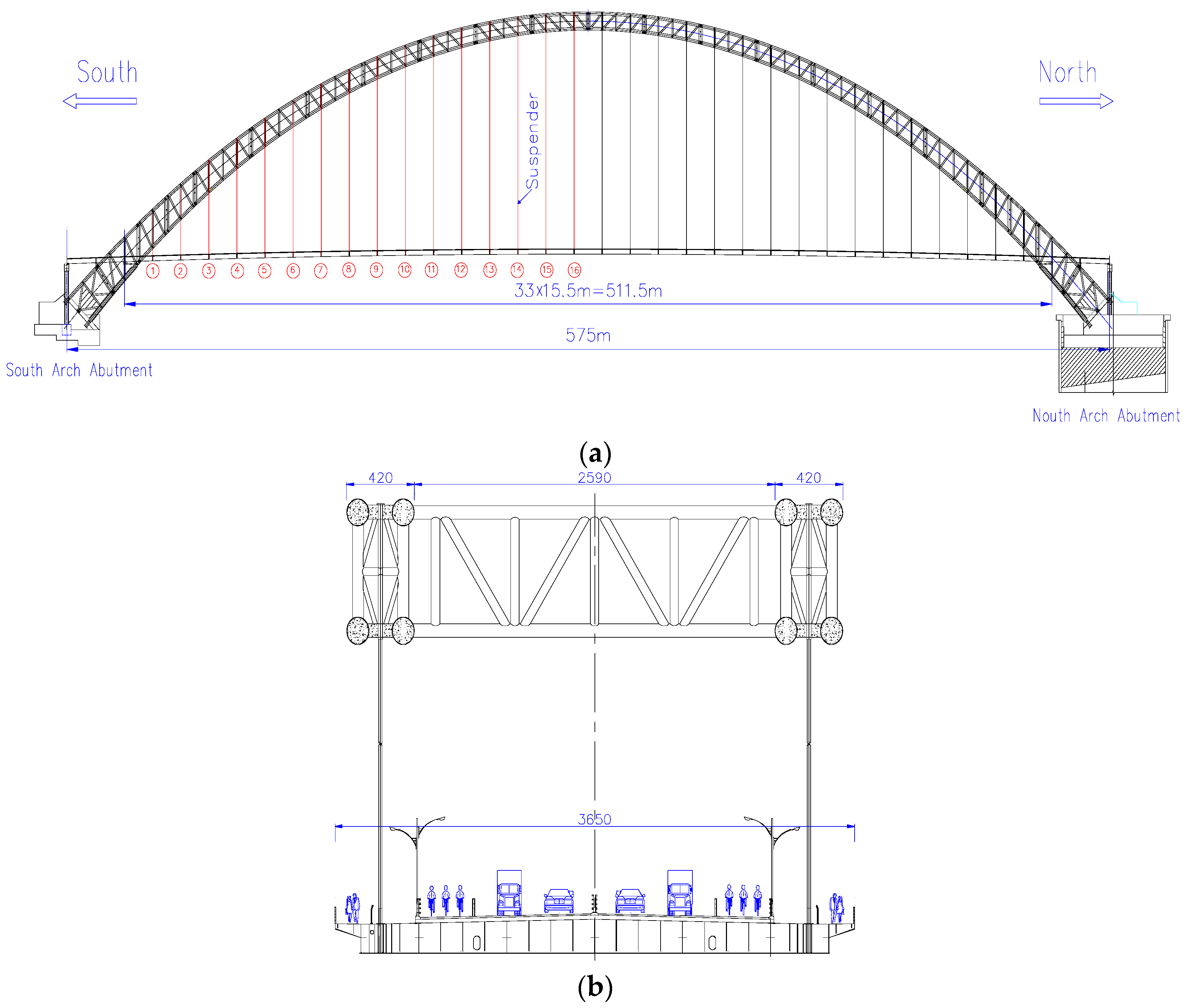
Figure 3.
The finite element model diagram.
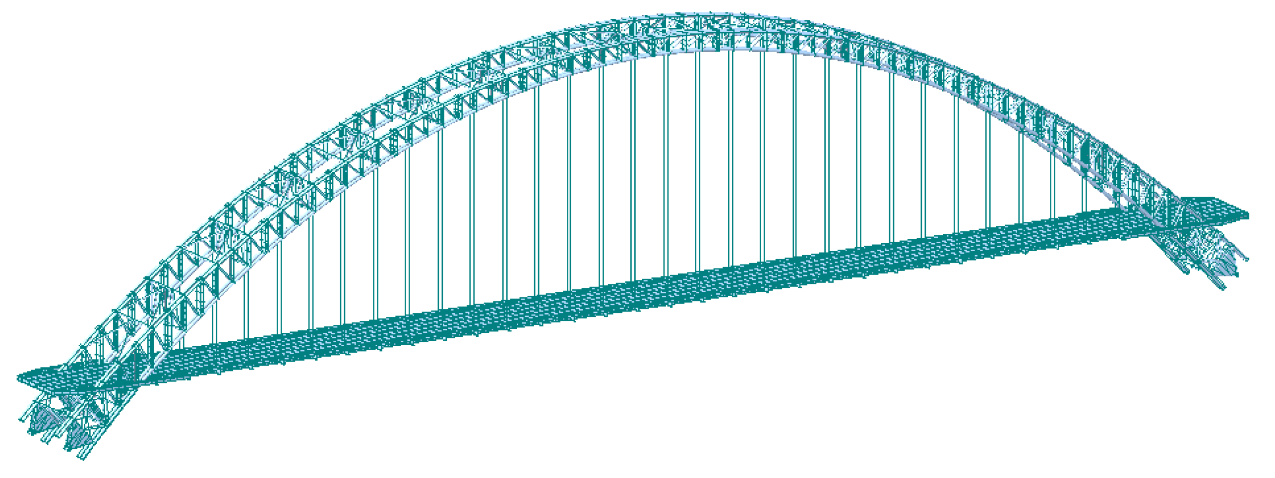
Figure 4.
The relationship between the allowable value (delta) and optimization dispersion (favor).
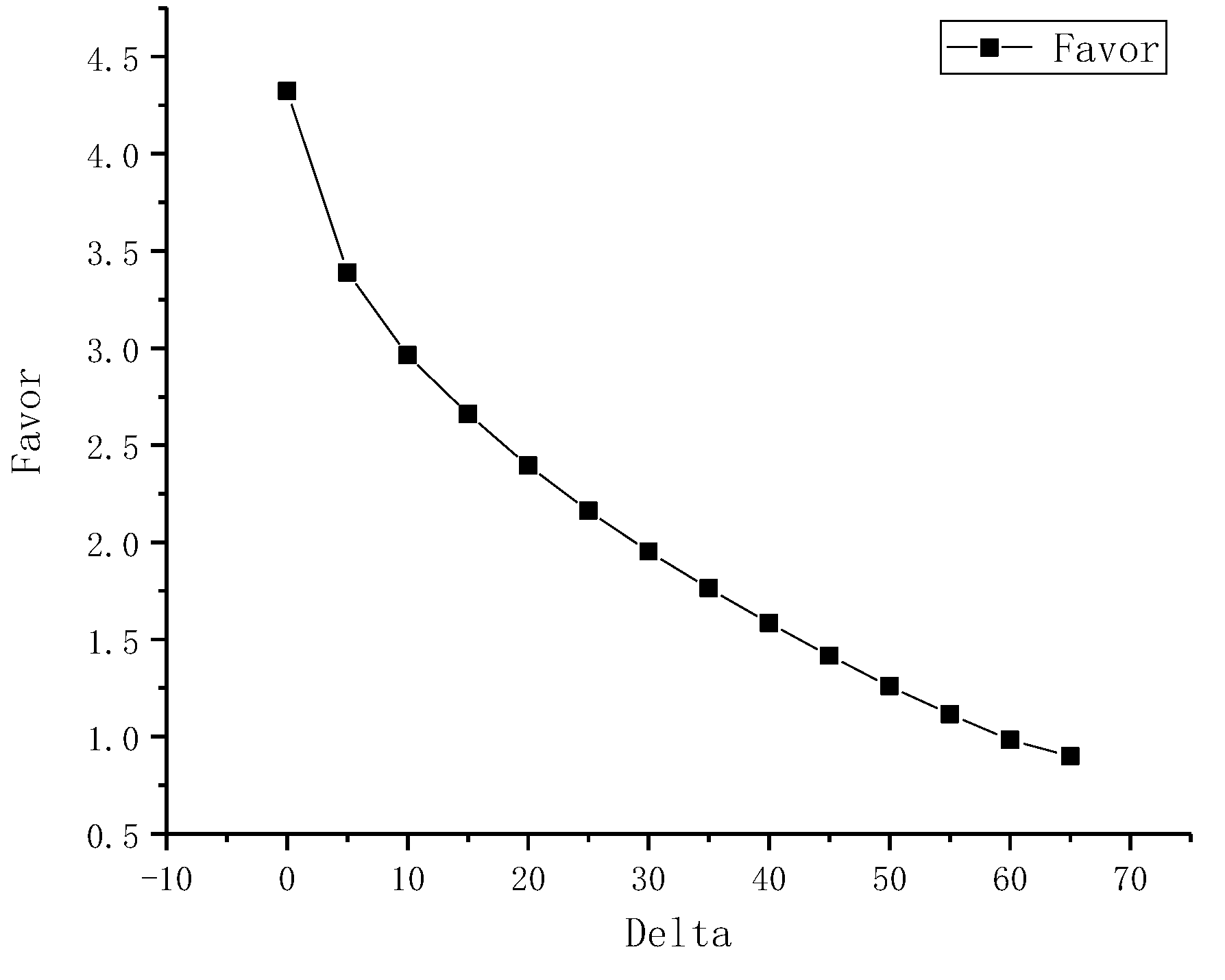
Figure 5.
The relationship between the delta value and initial tension value for suspenders.
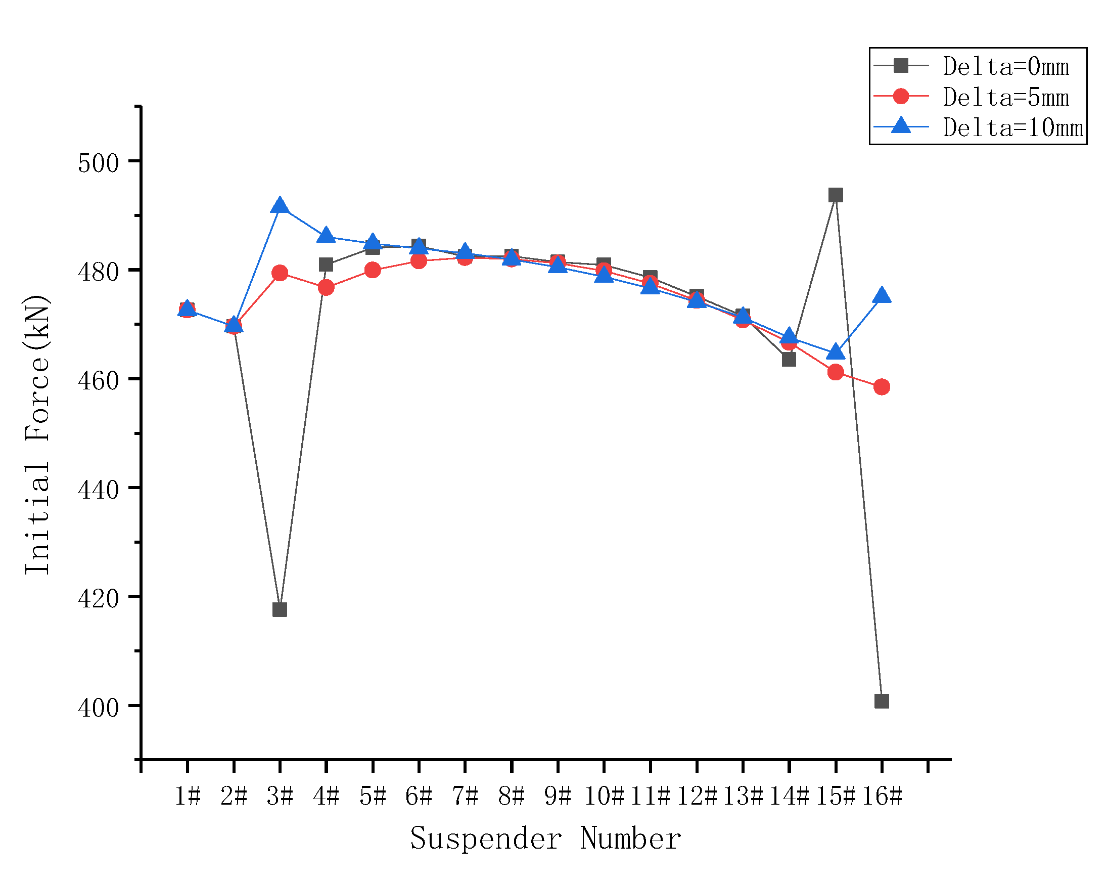
Figure 6.
The relationship between the delta value and suspender cable force after the completion of bridge.
Figure 6.
The relationship between the delta value and suspender cable force after the completion of bridge.
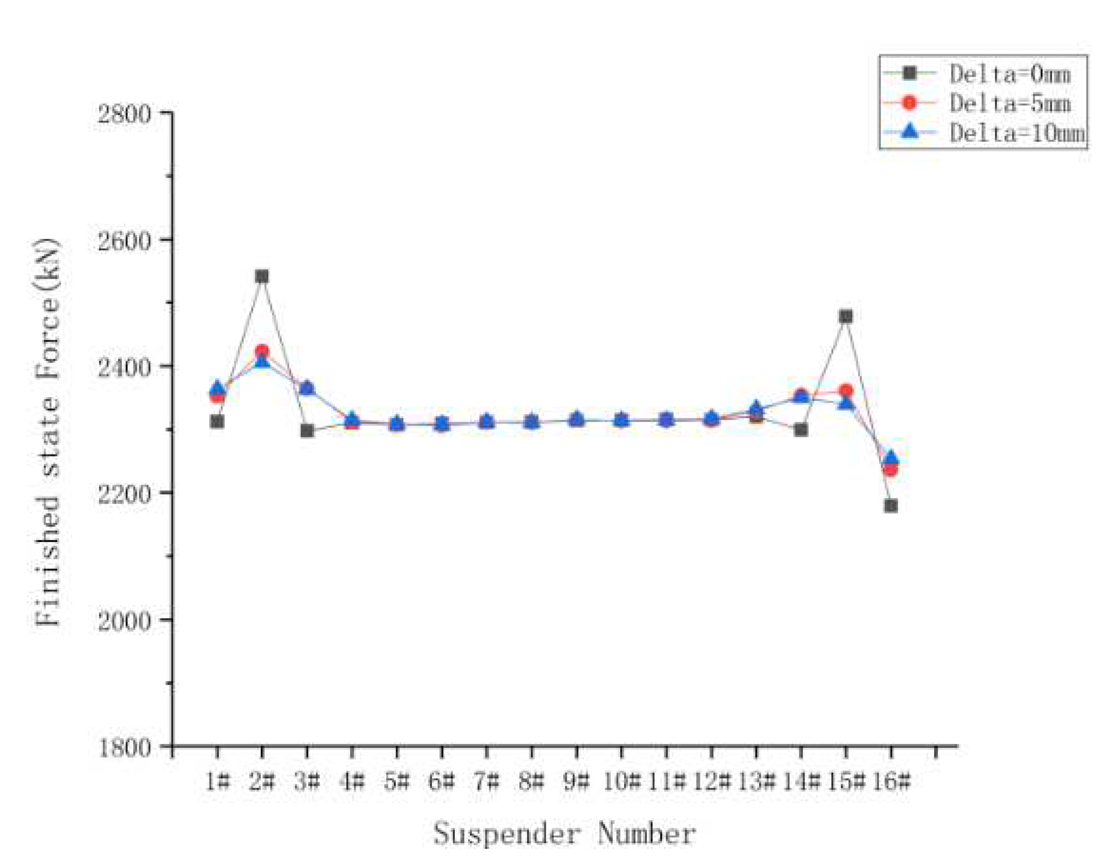
Figure 7.
The relationship between the delta value and displacement of control points of grid beam in the tension sections.
Figure 7.
The relationship between the delta value and displacement of control points of grid beam in the tension sections.
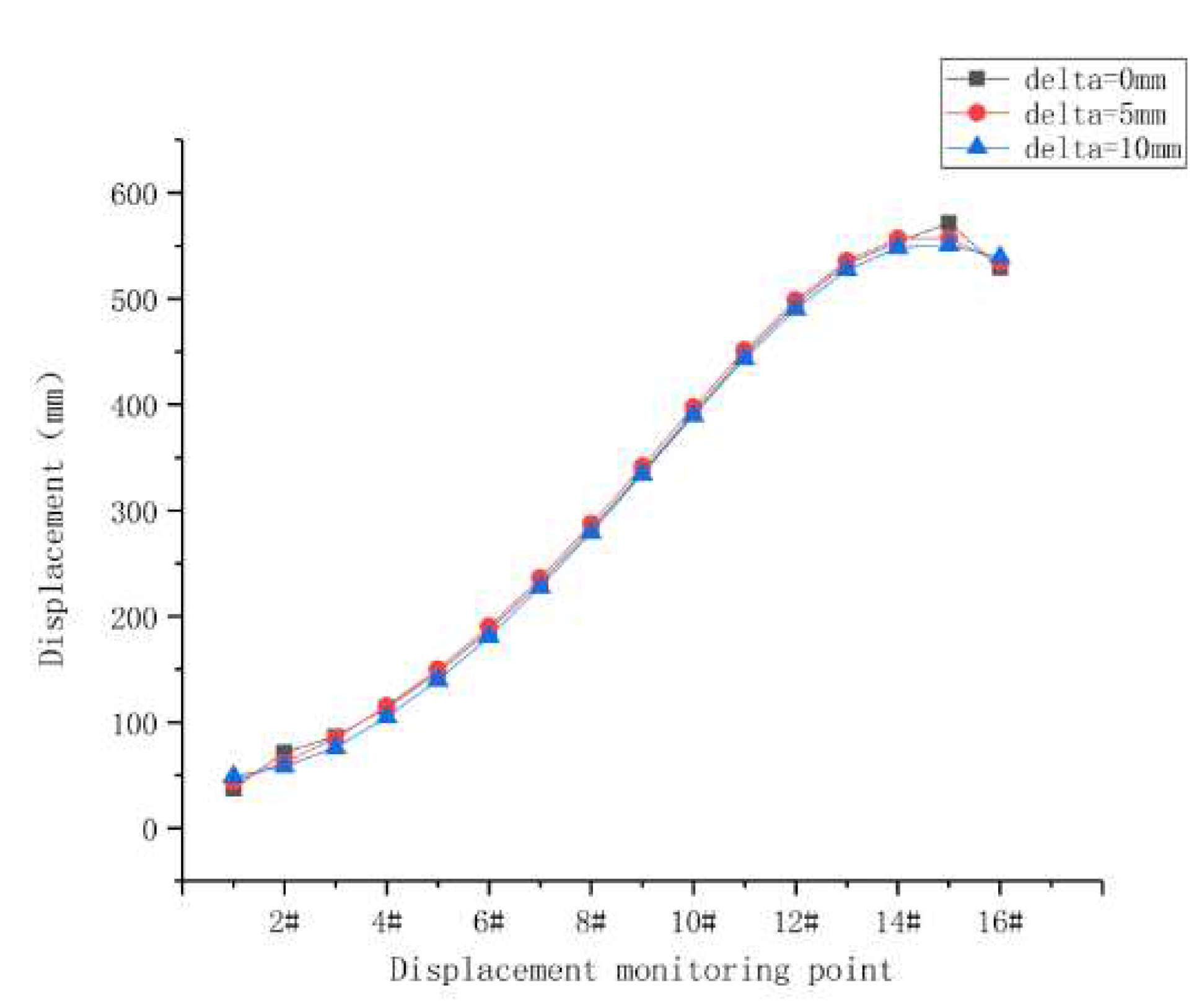
Figure 8.
The variation curves of suspender cable force versus construction stages.
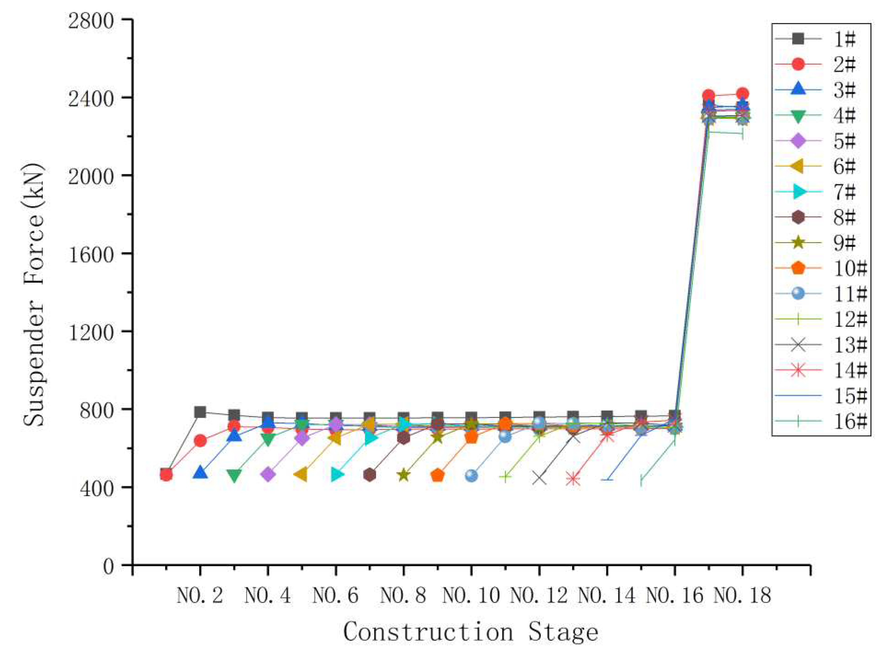
Figure 9.
The variation curves of displacement results of grid beam at the hoisting points versus construction stages.
Figure 9.
The variation curves of displacement results of grid beam at the hoisting points versus construction stages.
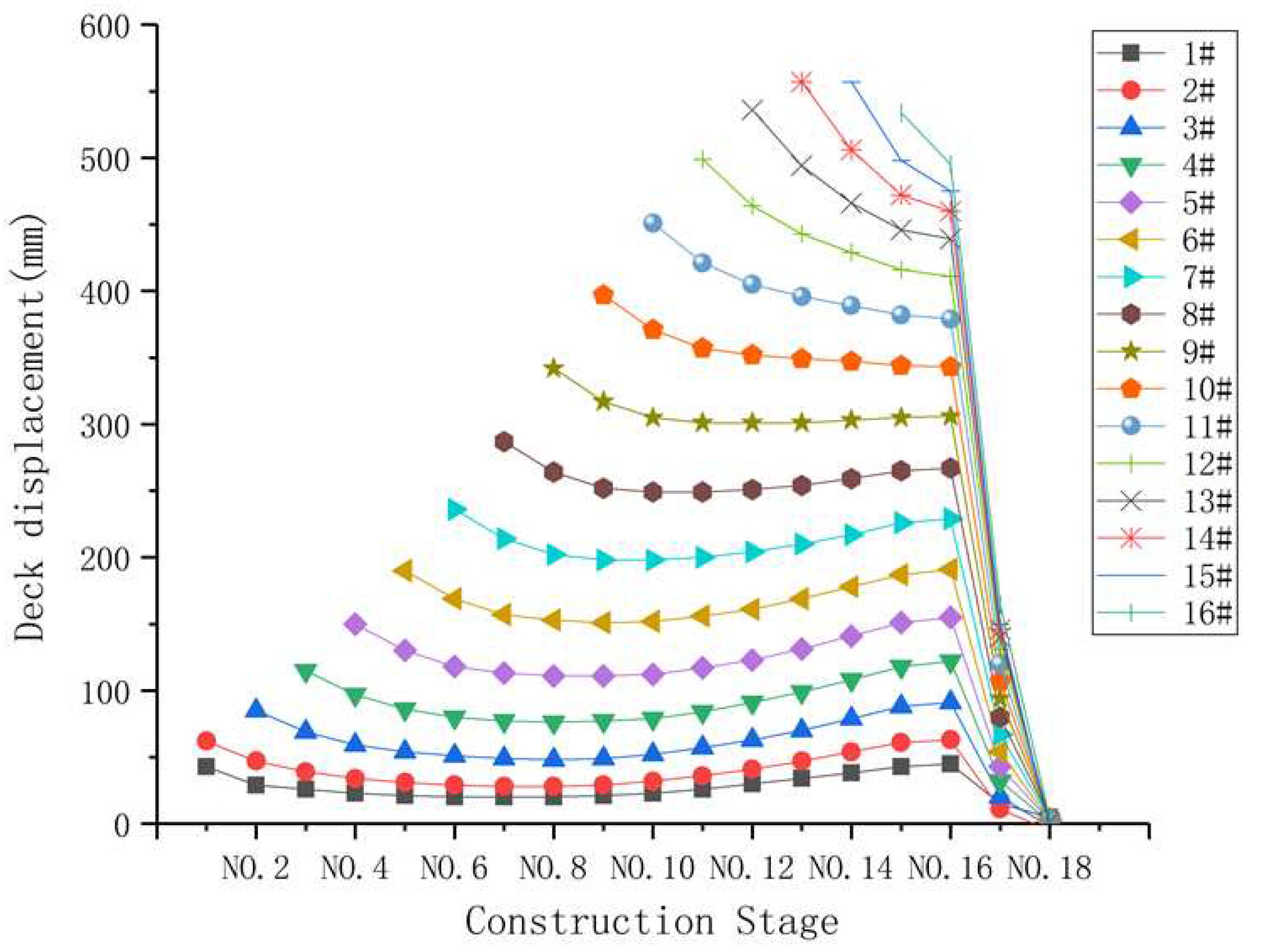
Figure 10.
The variation curves of arch rib displacement results at the hoisting points versus construction stages.
Figure 10.
The variation curves of arch rib displacement results at the hoisting points versus construction stages.
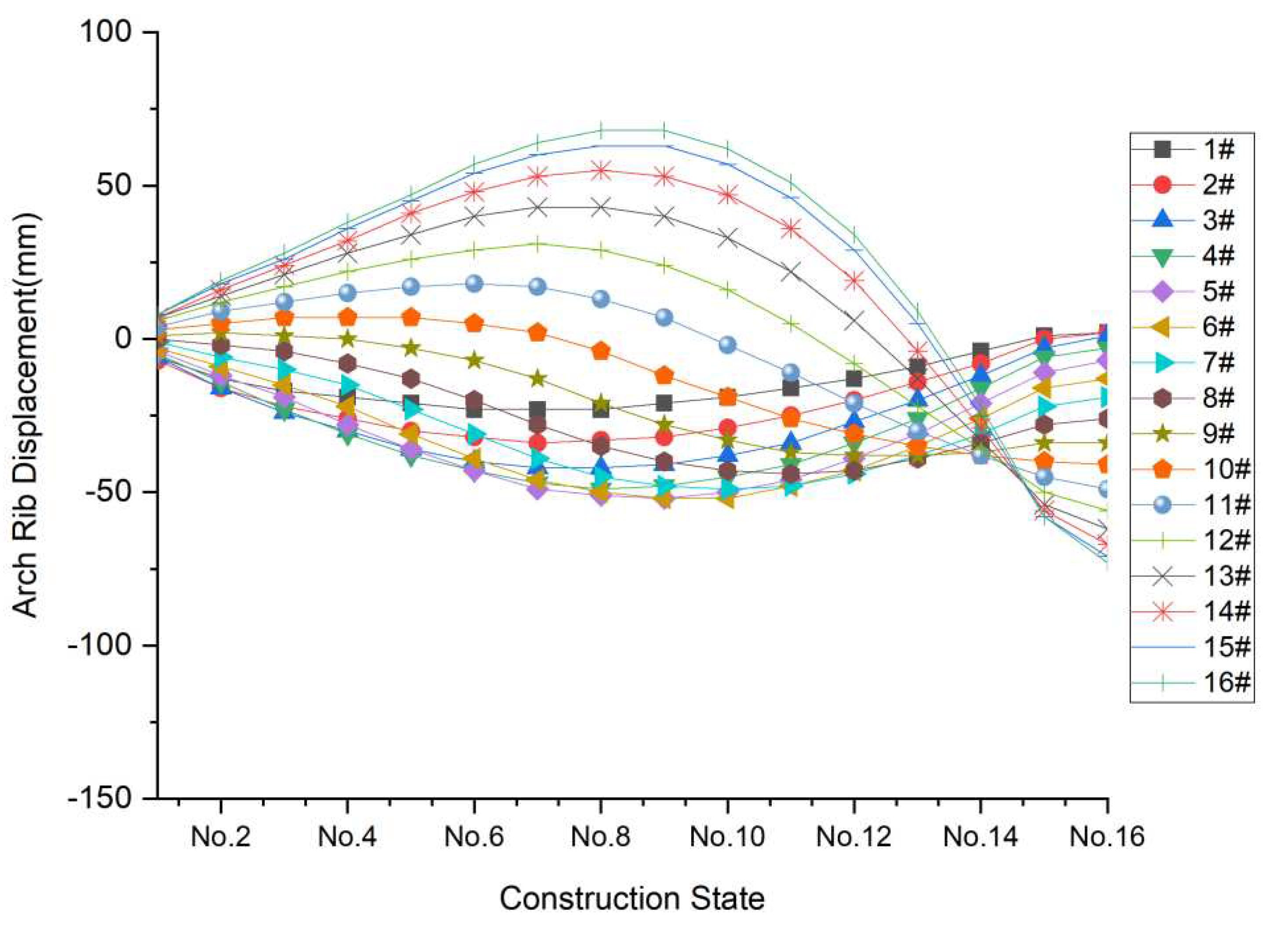
Figure 11.
The comparison of suspender cable forces after the completion of bridge by the proposed method and minimum bending energy method.
Figure 11.
The comparison of suspender cable forces after the completion of bridge by the proposed method and minimum bending energy method.
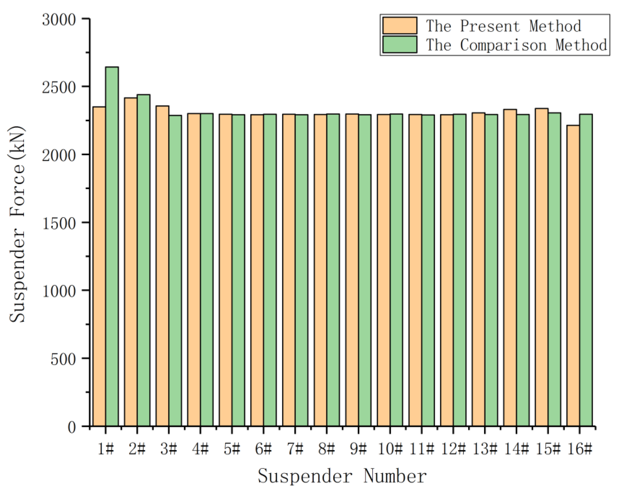

Table 1.
The properties of the materials used in the Third Pingnan Bridge.
| Components | Elastic Modulus/MPa | Bulk Density/kN·m−3 | Section Size/mm |
|---|---|---|---|
| Main chord tube | 2.06 × 10⁵ | 78 | Φ 1400 × 26 |
| Suspender | 1.95 × 10⁵ | 78 | 37 Φ 15.2 |
| Main beam | 2.06 × 10⁵ | 78 | 2200 |
| C40 | 3.25 × 10⁴ | 25 | 240/150 |
| C70 | 3.70 × 10⁴ | 25 | Φ 1400 |
Table 2.
Suspender cable force values in different construction sections.
| Construction Stage | Suspender Cable Force Values in Different Construction Sections/kN | |||||||||||||||
|---|---|---|---|---|---|---|---|---|---|---|---|---|---|---|---|---|
| 1# | 2# | 3# | 4# | 5# | 6# | 7# | 8# | 9# | 10# | 11# | 12# | 13# | 14# | 15# | 16# | |
| 1# and 2# tension | 468 | 463 | 0 | 0 | 0 | 0 | 0 | 0 | 0 | 0 | 0 | 0 | 0 | 0 | 0 | 0 |
| 3# tension | 784 | 638 | 470 | 0 | 0 | 0 | 0 | 0 | 0 | 0 | 0 | 0 | 0 | 0 | 0 | 0 |
| 4# tension | 769 | 711 | 660 | 466 | 0 | 0 | 0 | 0 | 0 | 0 | 0 | 0 | 0 | 0 | 0 | 0 |
| 5# tension | 757 | 707 | 730 | 652 | 467 | 0 | 0 | 0 | 0 | 0 | 0 | 0 | 0 | 0 | 0 | 0 |
| 6# tension | 754 | 697 | 727 | 722 | 652 | 467 | 0 | 0 | 0 | 0 | 0 | 0 | 0 | 0 | 0 | 0 |
| 7# tension | 755 | 694 | 717 | 721 | 722 | 653 | 466 | 0 | 0 | 0 | 0 | 0 | 0 | 0 | 0 | 0 |
| 8# tension | 755 | 695 | 713 | 711 | 722 | 723 | 654 | 464 | 0 | 0 | 0 | 0 | 0 | 0 | 0 | 0 |
| 9# tension | 755 | 697 | 713 | 706 | 711 | 723 | 723 | 654 | 462 | 0 | 0 | 0 | 0 | 0 | 0 | 0 |
| 10# tension | 756 | 698 | 714 | 706 | 707 | 713 | 724 | 724 | 655 | 460 | 0 | 0 | 0 | 0 | 0 | 0 |
| 11# tension | 757 | 698 | 714 | 707 | 706 | 708 | 713 | 725 | 725 | 657 | 457 | 0 | 0 | 0 | 0 | 0 |
| 12# tension | 758 | 699 | 715 | 707 | 707 | 707 | 708 | 714 | 725 | 726 | 659 | 453 | 0 | 0 | 0 | 0 |
| 13# tension | 759 | 699 | 715 | 707 | 707 | 708 | 707 | 708 | 713 | 726 | 728 | 661 | 449 | 0 | 0 | 0 |
| 14# tension | 761 | 700 | 715 | 707 | 708 | 708 | 708 | 707 | 708 | 714 | 726 | 730 | 663 | 444 | 0 | 0 |
| 15# tension | 762 | 700 | 715 | 707 | 708 | 708 | 709 | 708 | 707 | 708 | 714 | 727 | 731 | 667 | 438 | 0 |
| 16# tension | 764 | 701 | 715 | 707 | 708 | 708 | 709 | 709 | 708 | 707 | 708 | 714 | 727 | 734 | 666 | 435 |
| Closure stage | 765 | 701 | 715 | 707 | 708 | 708 | 709 | 709 | 708 | 708 | 706 | 707 | 717 | 743 | 750 | 643 |
| After pavement | 2358 | 2408 | 2347 | 2299 | 2293 | 2293 | 2295 | 2294 | 2295 | 2294 | 2292 | 2293 | 2304 | 2329 | 2336 | 2222 |
Table 3.
Displacement values for the grid beam at the hoisting points in different construction sections.
Table 3.
Displacement values for the grid beam at the hoisting points in different construction sections.
| Construction Stage | Displacement Values for the Grid Beam in Different Construction Sections/mm | |||||||||||||||
|---|---|---|---|---|---|---|---|---|---|---|---|---|---|---|---|---|
| 1# | 2# | 3# | 4# | 5# | 6# | 7# | 8# | 9# | 10# | 11# | 12# | 13# | 14# | 15# | 16# | |
| 1# and 2# tension | 43 | 62 | - | - | - | - | - | - | - | - | - | - | - | - | - | - |
| 3# tension | 29 | 47 | 85 | - | - | - | - | - | - | - | - | - | - | - | - | - |
| 4# tension | 26 | 39 | 69 | 115 | - | - | - | - | - | - | - | - | - | - | - | - |
| 5# tension | 23 | 34 | 59 | 97 | 150 | - | - | - | - | - | - | - | - | - | - | - |
| 6# tension | 21 | 31 | 54 | 86 | 130 | 190 | - | - | - | - | - | - | - | - | - | - |
| 7# tension | 20 | 29 | 51 | 80 | 118 | 169 | 236 | - | - | - | - | - | - | - | - | - |
| 8# tension | 20 | 28 | 49 | 77 | 113 | 157 | 214 | 287 | - | - | - | - | - | - | - | - |
| 9# tension | 20 | 28 | 48 | 76 | 111 | 153 | 202 | 264 | 342 | - | - | - | - | - | - | - |
| 10# tension | 21 | 29 | 49 | 77 | 111 | 151 | 198 | 252 | 317 | 397 | - | - | - | - | - | - |
| 11# tension | 23 | 32 | 52 | 79 | 112 | 152 | 198 | 249 | 305 | 371 | 451 | - | - | - | - | - |
| 12# tension | 26 | 36 | 57 | 84 | 117 | 156 | 200 | 249 | 301 | 357 | 421 | 499 | - | - | - | - |
| 13# tension | 30 | 41 | 63 | 91 | 123 | 161 | 204 | 251 | 301 | 352 | 405 | 464 | 536 | - | - | - |
| 14# tension | 34 | 47 | 70 | 99 | 131 | 169 | 210 | 254 | 301 | 349 | 396 | 443 | 494 | 557 | - | - |
| 15# tension | 38 | 54 | 79 | 108 | 141 | 178 | 217 | 259 | 303 | 347 | 389 | 429 | 466 | 506 | 557 | - |
| 16# tension | 43 | 61 | 88 | 118 | 151 | 187 | 226 | 265 | 305 | 344 | 382 | 416 | 446 | 472 | 498 | 534 |
| Closure stage | 45 | 63 | 91 | 122 | 155 | 191 | 229 | 267 | 306 | 343 | 379 | 411 | 439 | 460 | 475 | 495 |
| After pavement | 15 | 11 | 20 | 32 | 43 | 54 | 67 | 80 | 94 | 107 | 120 | 131 | 140 | 146 | 150 | 164 |
| Shrinkage and creep | 5 | −5 | −2 | 1 | 2 | 2 | 3 | 4 | 4 | 4 | 3 | 3 | 1 | −3 | −4 | 4 |
Table 4.
Arch rib displacement results at the hoisting points in different construction sections.
| Construction Stage | Arch Rib Displacement in Different Construction Sections/mm | |||||||||||||||
|---|---|---|---|---|---|---|---|---|---|---|---|---|---|---|---|---|
| 1# | 2# | 3# | 4# | 5# | 6# | 7# | 8# | 9# | 10# | 11# | 12# | 13# | 14# | 15# | 16# | |
| 1# and 2# tension | −6 | −7 | −6 | −5 | −4 | −3 | −1 | 0 | 1 | 3 | 4 | 6 | 7 | 7 | 8 | 8 |
| 3# tension | −13 | −16 | −16 | −14 | −12 | −9 | −6 | −2 | 2 | 5 | 9 | 12 | 14 | 16 | 18 | 19 |
| 4# tension | −17 | −22 | −24 | −23 | −19 | −15 | −10 | −4 | 1 | 7 | 12 | 17 | 21 | 24 | 26 | 28 |
| 5# tension | −19 | −26 | −30 | −31 | −28 | −22 | −15 | −8 | 0 | 7 | 15 | 22 | 28 | 32 | 36 | 38 |
| 6# tension | −21 | −30 | −36 | −38 | −36 | −31 | −23 | −13 | −3 | 7 | 17 | 26 | 34 | 41 | 45 | 47 |
| 7# tension | −23 | −32 | −40 | −43 | −43 | −39 | −31 | −20 | −7 | 5 | 18 | 29 | 40 | 48 | 54 | 57 |
| 8# tension | −23 | −34 | −42 | −47 | −49 | −46 | −39 | −28 | −13 | 2 | 17 | 31 | 43 | 53 | 60 | 64 |
| 9# tension | −23 | −33 | −42 | −49 | −51 | −50 | −45 | −35 | −21 | −4 | 13 | 29 | 43 | 55 | 63 | 68 |
| 10# tension | −21 | −32 | −41 | −48 | −52 | −52 | −48 | −40 | −28 | −12 | 7 | 24 | 40 | 53 | 63 | 68 |
| 11# tension | −19 | −29 | −38 | −45 | −50 | −52 | −49 | −43 | −33 | −19 | −2 | 16 | 33 | 47 | 57 | 62 |
| 12# tension | −16 | −25 | −34 | −41 | −46 | −48 | −48 | −44 | −37 | −26 | −11 | 5 | 22 | 36 | 46 | 51 |
| 13# tension | −13 | −20 | −27 | −34 | −39 | −43 | −44 | −43 | −38 | −31 | −21 | −8 | 6 | 19 | 29 | 34 |
| 14# tension | −9 | −14 | −20 | −26 | −31 | −35 | −38 | −39 | −38 | −35 | −30 | −22 | −13 | −4 | 5 | 9 |
| 15# tension | −4 | −8 | −12 | −16 | −21 | −26 | −31 | −34 | −37 | −38 | −38 | −36 | −33 | −29 | −25 | −22 |
| 16# tension | 1 | 0 | −3 | −6 | −11 | −16 | −22 | −28 | −34 | −40 | −45 | −50 | −54 | −56 | −58 | −58 |
| Closure stage | 2 | 2 | 1 | −3 | −7 | −13 | −19 | −26 | −34 | −41 | −49 | −56 | −62 | −67 | −71 | −73 |
| After pavement | 6 | 7 | 2 | −6 | −19 | −35 | −54 | −75 | −98 | −122 | −145 | −168 | −188 | −204 | −217 | −225 |
Table 5.
The comparison of the bearing reaction using the proposed method and the minimum bending energy method.
Table 5.
The comparison of the bearing reaction using the proposed method and the minimum bending energy method.
| Methods | Bridge Components/kN | |||
|---|---|---|---|---|
| Beam End | Column and Cross Beam Between Ribs | Suspender | Resultant Force | |
| The proposed method | 4659 | 20,180 | 147,845 | 172,684 |
| Minimum bending energy method | 4993 | 18,852 | 148,838 | 172,684 |
| Difference | −335 | 1328 | −993 | 0 |
Disclaimer/Publisher’s Note: The statements, opinions and data contained in all publications are solely those of the individual author(s) and contributor(s) and not of MDPI and/or the editor(s). MDPI and/or the editor(s) disclaim responsibility for any injury to people or property resulting from any ideas, methods, instructions or products referred to in the content. |
© 2023 by the authors. Licensee MDPI, Basel, Switzerland. This article is an open access article distributed under the terms and conditions of the Creative Commons Attribution (CC BY) license (http://creativecommons.org/licenses/by/4.0/).
Copyright: This open access article is published under a Creative Commons CC BY 4.0 license, which permit the free download, distribution, and reuse, provided that the author and preprint are cited in any reuse.


