Submitted:
24 July 2023
Posted:
25 July 2023
You are already at the latest version
Abstract
Keywords:
1. Introduction
2. Materials and Methods
3. Results and discussions
4. Conclusions
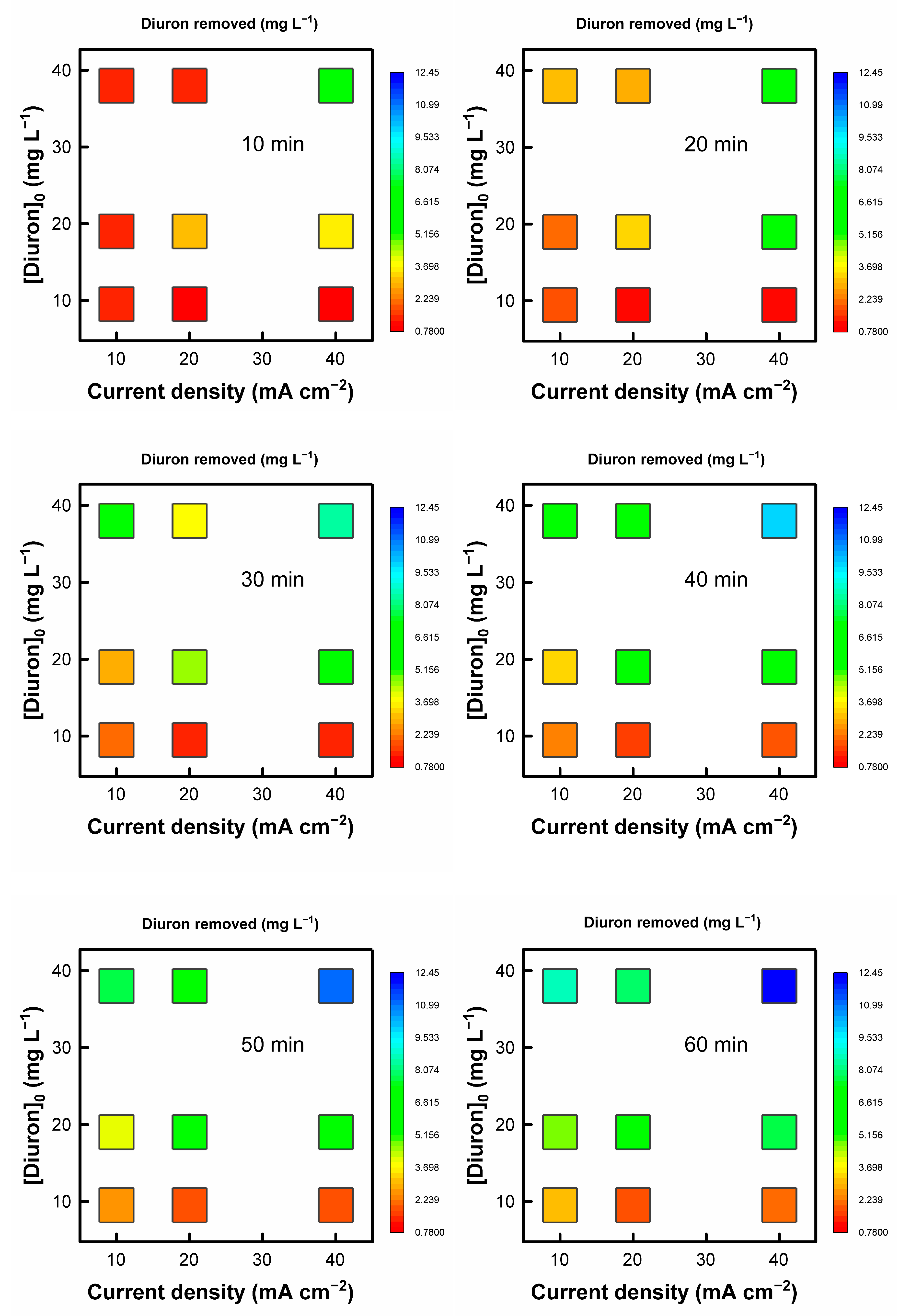
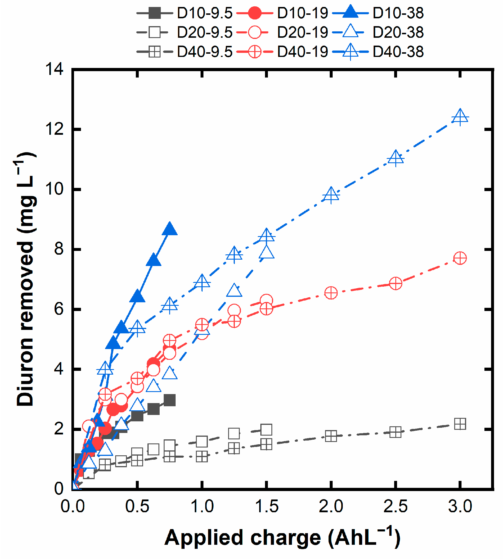
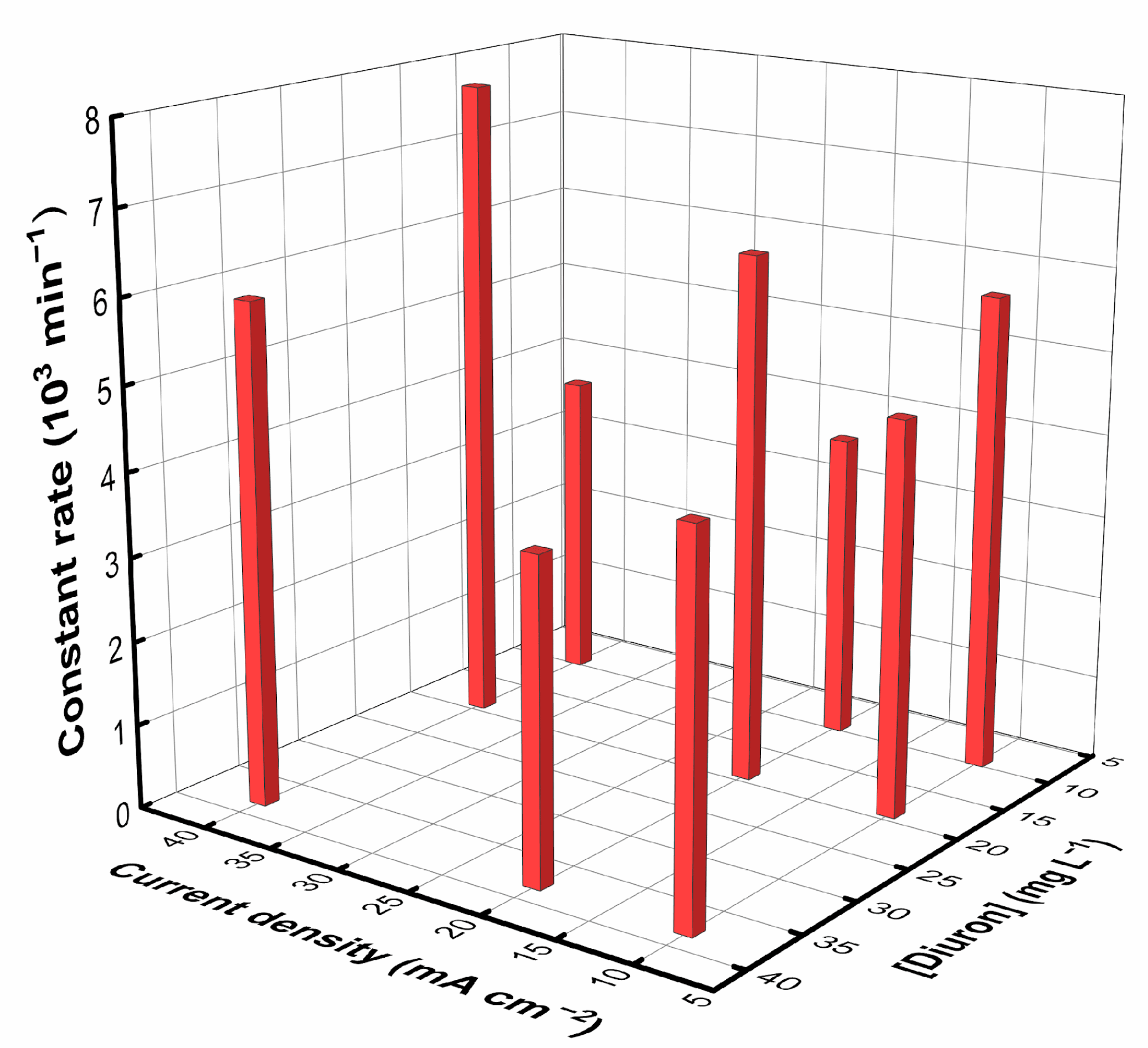
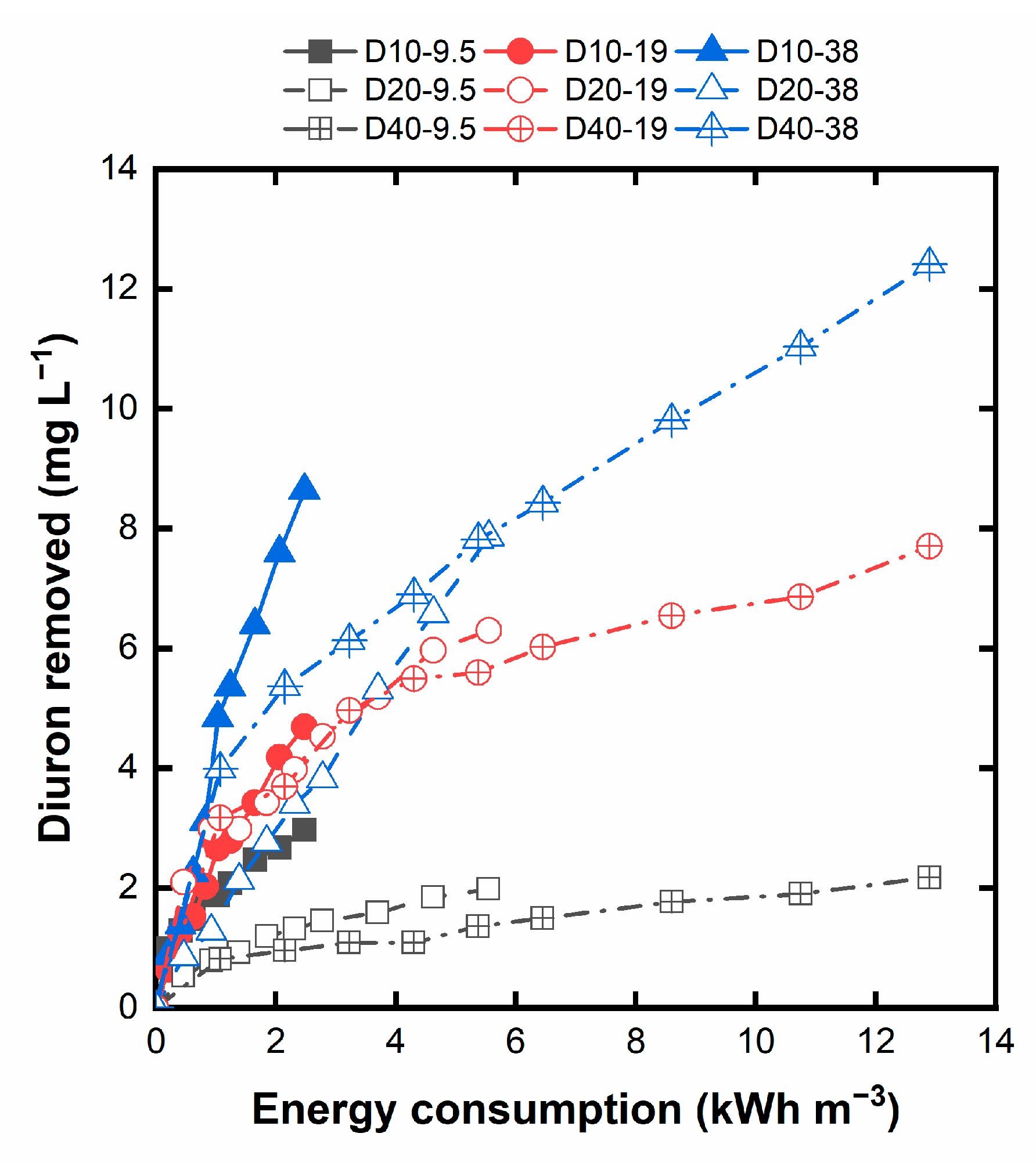
- In terms of a rapid Diuron degradation, the condition D40-38 is the most favorable owing to the synergy of the most oxidative conditions with the highest pollutant availability, accelerating the degradation process.
- Nevertheless, attention must be given to efficiency and energy consumption, in which case the operation at 10 mA cm−2, regardless of the initial Diuron concentration, becomes more attractive as it removes Diuron with the lowest applied charge and energy demand.
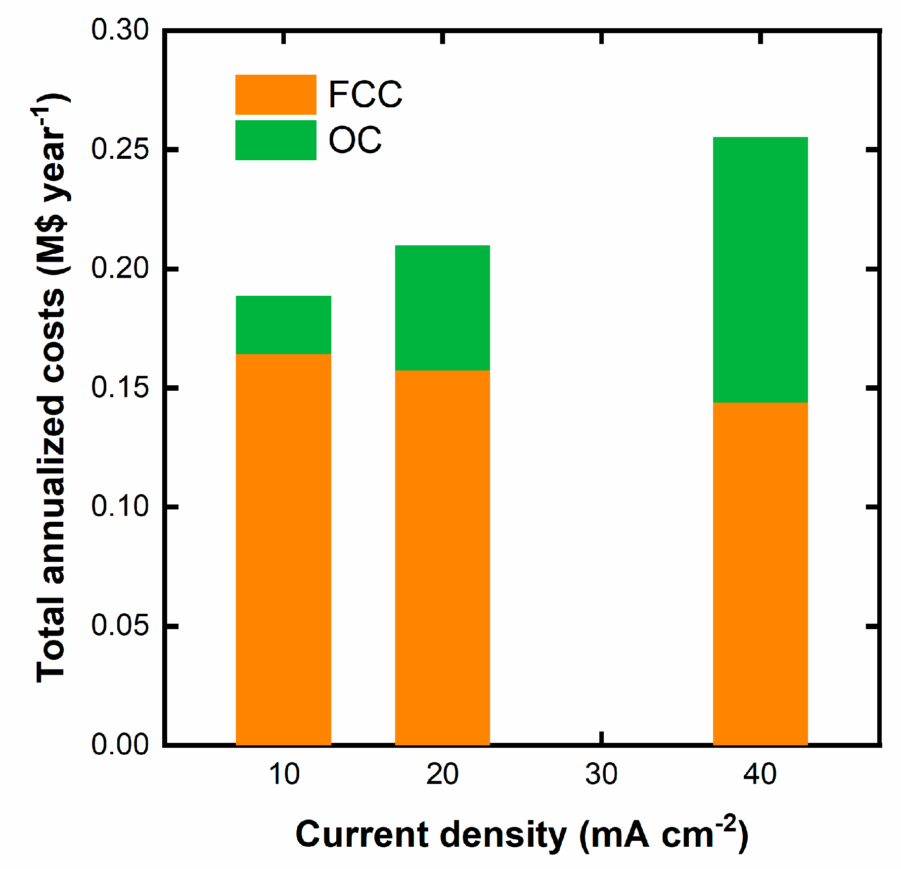
- This information drawn from the analysis of the influence of the operating parameters is precious for establishing the design and operating conditions of an electrochemical treatment plant based on the minimization of the costs.
- Operating in the most efficient conditions is beneficial for reducing the FCC, whose impact is more substantial than the OC, provided there is no significant increase in the cell voltage.
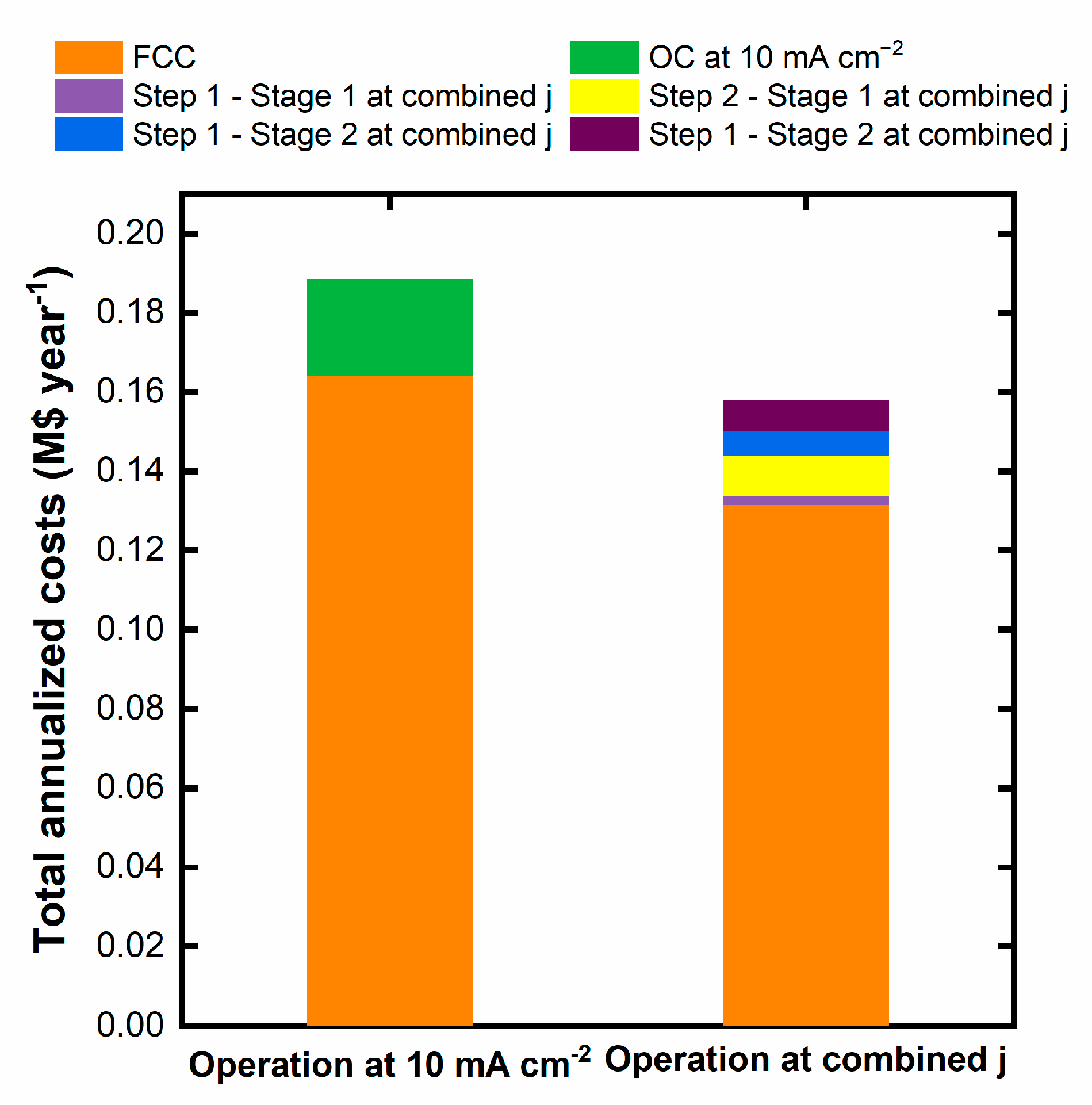
- In this latter sense, as demonstrated in the work, it may be interesting to modulate the applied current density during the treatment, beginning with a higher current density and reducing it as the degradation proceeds to guarantee the operation at the highest possible efficiency and lowest electricity consumption, minimizing the total costs of the systems.
Supplementary Materials
Author Contributions
Funding
Data Availability Statement
Acknowledgments
Conflicts of Interest
References
- Kishor, R.; Purchase, D.; Saratale, G.D.; Saratale, R.G.; Ferreira, L.F.R.; Bilal, M.; Chandra, R.; Bharagava, R.N. Ecotoxicological and Health Concerns of Persistent Coloring Pollutants of Textile Industry Wastewater and Treatment Approaches for Environmental Safety. J. Environ. Chem. Eng. 2021, 9, 105012. [Google Scholar] [CrossRef]
- Yakamercan, E.; Bhatt, P.; Aygun, A.; Adesope, A.W.; Simsek, H. Comprehensive Understanding of Electrochemical Treatment Systems Combined with Biological Processes for Wastewater Remediation. Environ. Pollut. 2023, 330, 121680. [Google Scholar] [CrossRef]
- Najafinejad, M.S.; Chianese, S.; Fenti, A.; Iovino, P.; Musmarra, D. Application of Electrochemical Oxidation for Water and Wastewater Treatment: An Overview. Molecules 2023, 28, 4208. [Google Scholar] [CrossRef]
- Martínez-Sánchez, C.; Robles, I.; Godínez, L.A. Review of Recent Developments in Electrochemical Advanced Oxidation Processes: Application to Remove Dyes, Pharmaceuticals, and Pesticides. Int. J. Environ. Sci. Technol. 2022, 19, 12611–12678. [Google Scholar] [CrossRef]
- Bellas, J.; García-Pimentel, M.d.M.; León, V.M. Current-Use Pesticides in the Marine Environment. In Contaminants of Emerging Concern in the Marine Environment; León, V.M., Bellas, J., Eds.; Elsevier: Amsterdam, Netherlands, 2023; pp. 229–309. [Google Scholar]
- Panis, C.; Candiotto, L.Z.P.; Gaboardi, S.C.; Gurzenda, S.; Cruz, J.; Castro, M.; Lemos, B. Widespread Pesticide Contamination of Drinking Water and Impact on Cancer Risk in Brazil. Environ. Int. 2022, 165, 107321. [Google Scholar] [CrossRef]
- European Food Safety Authority Conclusion Regarding the Peer Review of the Pesticide Risk Assessment of the Active Substance Diuron. EFSA J. 2005, 3, 1–58. [CrossRef]
- Martínez-Huitle, C.A.; Rodrigo, M.A.; Sirés, I.; Scialdone, O. Single and Coupled Electrochemical Processes and Reactors for the Abatement of Organic Water Pollutants: A Critical Review. Chem. Rev. 2015, 115, 13362–13407. [Google Scholar] [CrossRef]
- Comninellis, C.; Kapalka, A.; Malato, S.; Parsons, S.A.; Poulios, I.; Mantzavinos, D. Advanced Oxidation Processes for Water Treatment: Advances and Trends for R&D. J. Chem. Technol. Biotechnol. 2008, 83, 769–776. [Google Scholar] [CrossRef]
- Freitas, J.M.; Oliveira, T. da C.; Munoz, R.A.A.; Richter, E.M. Boron Doped Diamond Electrodes in Flow-Based Systems. Front. Chem. 2019, 7, 190. [Google Scholar] [CrossRef]
- Wenderich, K.; Nieuweweme, B.A.M.; Mul, G.; Mei, B.T. Selective Electrochemical Oxidation of H2O to H2O2 Using Boron-Doped Diamond: An Experimental and Techno-Economic Evaluation. ACS Sustain. Chem. Eng. 2021, 9, 7803–7812. [Google Scholar] [CrossRef]
- Bergmann, M.E.H.; Rollin, J.; Iourtchouk, T. The Occurrence of Perchlorate during Drinking Water Electrolysis Using BDD Anodes. Electrochim. Acta 2009, 54, 2102–2107. [Google Scholar] [CrossRef]
- Radjenovic, J.; Sedlak, D.L. Challenges and Opportunities for Electrochemical Processes as Next-Generation Technologies for the Treatment of Contaminated Water. Environ. Sci. Technol. 2015, 49, 11292–11302. [Google Scholar] [CrossRef]
- Santos, G.O.S.; Dória, A.R.; Vasconcelos, V.M.; Sáez, C.; Rodrigo, M.A.; Eguiluz, K.I.B.; Salazar-Banda, G.R. Enhancement of Wastewater Treatment Using Novel Laser-Made Ti/SnO2–Sb Anodes with Improved Electrocatalytic Properties. Chemosphere 2020, 259, 127475. [Google Scholar] [CrossRef]
- Dória, A.R.; Gonzaga, I.M.D.; Santos, G.O.S.; Pupo, M.; Silva, D.C.; Silva, R.S.; Rodrigo, M.A.; Eguiluz, K.I.B.; Salazar-Banda, G.R. Ultra-Fast Synthesis of Ti/Ru0.3Ti0.7O2 Anodes with Superior Electrochemical Properties Using an Ionic Liquid and Laser Calcination. Chem. Eng. J. 2021, 416, 129011. [Google Scholar] [CrossRef]
- Gonzaga, I.M.D.; Moratalla, A.; Eguiluz, K.I.B.; Salazar-Banda, G.R.; Cañizares, P.; Rodrigo, M.A.; Saez, C. Outstanding Performance of the Microwave-Made MMO-Ti/RuO2IrO2 Anode on the Removal of Antimicrobial Activity of Penicillin G by Photoelectrolysis. Chem. Eng. J. 2021, 420, 129999. [Google Scholar] [CrossRef]
- Gonzaga, I.M.D.; Dória, A.R.; Castro, R.S.S.; Souza, M.R.R.; Rodrigo, M.A.; Eguiluz, K.I.B.; Salazar-Banda, G.R. Microwave-Prepared Ti/RuO2-IrO2 Anodes: Influence of IrO2 Content on Atrazine Removal. Electrochim. Acta 2022, 426, 140782. [Google Scholar] [CrossRef]
- Zhao, R.; Zhang, X.; Chen, F.; Man, X.; Jiang, W. Study on Electrochemical Degradation of Nicosulfuron by IrO2-Based DSA Electrodes: Performance, Kinetics, and Degradation Mechanism. Int. J. Environ. Res. Public Health 2019, 16, 343. [Google Scholar] [CrossRef]
- Moreno-Palacios, A. V.; Palma-Goyes, R.E.; Vazquez-Arenas, J.; Torres-Palma, R.A. Bench-Scale Reactor for Cefadroxil Oxidation and Elimination of Its Antibiotic Activity Using Electro-Generated Active Chlorine. J. Environ. Chem. Eng. 2019, 7, 103173. [Google Scholar] [CrossRef]
- Espinoza, L.C.; Sepúlveda, P.; García, A.; Martins de Godoi, D.; Salazar, R. Degradation of Oxamic Acid Using Dimensionally Stable Anodes (DSA) Based on a Mixture of RuO2 and IrO2 Nanoparticles. Chemosphere 2020, 251, 126674. [Google Scholar] [CrossRef]
- Santos, T.É.S.; Silva, R.S.; Eguiluz, K.I.B.; Salazar-Banda, G.R. Development of Ti/(RuO2)0.8(MO2)0.2 (M=Ce, Sn or Ir) Anodes for Atrazine Electro-Oxidation. Influence of the Synthesis Method. Mater. Lett. 2015, 146, 4–8. [Google Scholar] [CrossRef]
- Malpass, G.R.P.; Miwa, D.W.; Machado, S.A.S.; Olivi, P.; Motheo, A.J. Oxidation of the Pesticide Atrazine at DSA® Electrodes. J. Hazard. Mater. 2006, 137, 565–572. [Google Scholar] [CrossRef] [PubMed]
- Vlyssides, A.; Arapoglou, D.; Mai, S.; Barampouti, E.M. Electrochemical Detoxification of Four Phosphorothioate Obsolete Pesticides Stocks. Chemosphere 2005, 58, 439–447. [Google Scholar] [CrossRef] [PubMed]
- Arapoglou, D.; Vlyssides, A.; Israilides, C.; Zorpas, A.; Karlis, P. Detoxification of Methyl-Parathion Pesticide in Aqueous Solutions by Electrochemical Oxidation. J. Hazard. Mater. 2003, 98, 191–199. [Google Scholar] [CrossRef] [PubMed]
- Malpass, G.R.P.; Miwa, D.W.; Miwa, A.C.P.; Machado, S.A.S.; Motheo, A.J. Study of Photo-Assisted Electrochemical Degradation of Carbaryl at Dimensionally Stable Anodes (DSA®). J. Hazard. Mater. 2009, 167, 224–229. [Google Scholar] [CrossRef] [PubMed]
- Zheng, Z.; Deletic, A.; Toe, C.Y.; Amal, R.; Zhang, X.; Pickford, R.; Zhou, S.; Zhang, K. Photo-Electrochemical Oxidation Herbicides Removal in Stormwater: Degradation Mechanism and Pathway Investigation. J. Hazard. Mater. 2022, 436, 129239. [Google Scholar] [CrossRef]
- Rahmani, A.; Leili, M.; Seid-mohammadi, A.; Shabanloo, A.; Ansari, A.; Nematollahi, D.; Alizadeh, S. Improved Degradation of Diuron Herbicide and Pesticide Wastewater Treatment in a Three-Dimensional Electrochemical Reactor Equipped with PbO2 Anodes and Granular Activated Carbon Particle Electrodes. J. Clean. Prod. 2021, 322, 129094. [Google Scholar] [CrossRef]
- Zheng, Z.; Zhang, K.; Toe, C.Y.; Amal, R.; Zhang, X.; McCarthy, D.T.; Deletic, A. Stormwater Herbicides Removal with a Solar-Driven Advanced Oxidation Process: A Feasibility Investigation. Water Res. 2021, 190, 116783. [Google Scholar] [CrossRef]
- Pipi, A.R.F.; Aquino Neto, S.; Andrade, A.R. De Electrochemical Degradation of Diuron in Chloride Medium Using DSA® Based Anodes. J. Braz. Chem. Soc. 2013, 24, 1259–1266. [Google Scholar] [CrossRef]
- Khongthon, W.; Jovanovic, G.; Yokochi, A.; Sangvanich, P.; Pavarajarn, V. Degradation of Diuron via an Electrochemical Advanced Oxidation Process in a Microscale-Based Reactor. Chem. Eng. J. 2016, 292, 298–307. [Google Scholar] [CrossRef]
- Zhu, K.; Qi, H.; Sun, X.; Sun, Z. Anodic Oxidation of Diuron Using Co3O4/Graphite Composite Electrode at Low Applied Current. Electrochim. Acta 2019, 299, 853–862. [Google Scholar] [CrossRef]
- Bumroongsakulsawat, P.; Khongthon, W.; Pavarajarn, V. Degradation of Diuron in Water by Electrochemical Advanced Oxidation in a Microreactor: Effects of Anion Contamination on Degradation and Toxicity. J. Environ. Chem. Eng. 2020, 8, 103824. [Google Scholar] [CrossRef]
- Wu, W.; Huang, Z.-H.; Lim, T.-T. Recent Development of Mixed Metal Oxide Anodes for Electrochemical Oxidation of Organic Pollutants in Water. Appl. Catal. A Gen. 2014, 480, 58–78. [Google Scholar] [CrossRef]
- Liu, J. Phenylurea Herbicides. In Hayes' Handbook of Pesticide Toxicology; Krieger, R., Ed.; Elsevier: London, United Kingdom, 2010; pp. 1725–1731. [Google Scholar]
- Brillas, E.; Sirés, I.; Arias, C.; Cabot, P.L.; Centellas, F.; Rodríguez, R.M.; Garrido, J.A. Mineralization of Paracetamol in Aqueous Medium by Anodic Oxidation with a Boron-Doped Diamond Electrode. Chemosphere 2005, 58, 399–406. [Google Scholar] [CrossRef] [PubMed]
- Deng, J.; Shao, Y.; Gao, N.; Deng, Y.; Tan, C.; Zhou, S.; Hu, X. Multiwalled Carbon Nanotubes as Adsorbents for Removal of Herbicide Diuron from Aqueous Solution. Chem. Eng. J. 2012, 193–194, 339–347. [Google Scholar] [CrossRef]
- Panizza, M.; Michaud, P.A.; Cerisola, G.; Comninellis, C.H. Anodic Oxidation of 2-Naphthol at Boron-Doped Diamond Electrodes. J. Electroanal. Chem. 2001, 507, 206–214. [Google Scholar] [CrossRef]
- de Araújo, B.R.S.; Linares, J.J. Electrochemical Treatment of Cetrimonium Chloride with Boron-Doped Diamond Anodes. A Technical and Economical Approach. J. Environ. Manage. 2018, 214, 86–93. [Google Scholar] [CrossRef]
- Statista Average Retail Electricity Price for Industrial Consumers in the United States from 1970 to 2022. Available online: https://www.statista.com/statistics/190680/us-industrial-consumer-price-estimates-for-retail-electricity-since-1970/#:~:text=Industrial retail electricity price in the U.S. 1970-2022&text=Industrial consumers of electricity in,per kilowatt-hour in 2022.
- Coelho, E.R.C.; Brega, R.S. Evaluation of a Pilot System for Removal of the Herbicide 2,4-Dichlorophenoxyacetic Acid and Absorbance Determination after Clarification and Adsorption on Granular Activated Carbon. Eng. Sanit. e Ambient. 2023, 28, e20220170. [Google Scholar] [CrossRef]
- Kučić Grgić, D.; Ocelić Bulatović, V.; Cvetnić, M.; Dujmić Vučinić, Ž.; Vuković Domanovac, M.; Markić, M.; Bolanča, T. Biodegradation Kinetics of Diuron by Pseudomonas Aeruginosa FN and Optimization of Biodegradation Using Response Surface Methodology. Water Environ. J. 2020, 34, 61–73. [Google Scholar] [CrossRef]
- Towler, G.; Sinnott, R. Economic Evaluation of Projects. In Chemical Engineering Design; Towler, G., Sinnott, R., Eds.; Elsevier: Amsterdam, The Netherlands, 2022; pp. 305–337. [Google Scholar]
| Diuron concentration (mg L−1) | ||||
| 9.5 | 19 | 38 | ||
| Current density (mA cm−2) | 10 | D10−9.5 | D10−19 | D10−38 |
| 20 | D20−9.5 | D20−19 | D20−38 | |
| 40 | D40−9.5 | D40−19 | D40−38 | |
| A (m2) | FCC (M$) = 10‒6 ⋅ A ⋅ 3500 $ m‒2 | Annualized FCC (M$ year−1) = 0.33 ⋅ CC | ||
| Current density (mA cm−2) | 10 | 146.6 | 0.513 | 0.164 |
| 20 | 140.4 | 0.492 | 0.157 | |
| 40 | 128.4 | 0.449 | 0.144 | |
| Vcell (V) | j (A m‒2) | A (m2) | OF (h year‒1) | OC (M$ year−1) | ||
| Current density (mA cm−2) | 10 | 3.3 | 100 | 146.6 | 6000 | 0.0244 |
| 20 | 3.7 | 200 | 140.4 | 6000 | 0.0525 | |
| 40 | 4.3 | 400 | 128.4 | 0.449 | 0.112 | |
| j (mA cm−2) | Q (ALh−1) | t (h) | Electrode area (m2) | Annualized CC (M$ year−1) | Operative electrode area (m2) | OC (M$ year−1) | Total annualized cost (M$ year−1) | |
| Stage 1 (38 → 19 mg L−1) | Step 1 → 40 | 0.250 | 0.148 | 117.4 | 0.131 | 102.0* | 0.00218 | (Total OC = 0.0164) 0.158 |
| Step 2 → 10 | 1.524 | 3.12 | 117.4 | 0.0102 | ||||
| Stage 2 (19 → 9.5 mg L−1) | Step 1 → 40 | 0.735 | 0.376 | 117.4 | 0.00639 | |||
| Step 2 → 10 | 1.15 | 2.36 | 117.4 | 0.00769 |
Disclaimer/Publisher’s Note: The statements, opinions and data contained in all publications are solely those of the individual author(s) and contributor(s) and not of MDPI and/or the editor(s). MDPI and/or the editor(s) disclaim responsibility for any injury to people or property resulting from any ideas, methods, instructions or products referred to in the content. |
© 2023 by the authors. Licensee MDPI, Basel, Switzerland. This article is an open access article distributed under the terms and conditions of the Creative Commons Attribution (CC BY) license (http://creativecommons.org/licenses/by/4.0/).


