1. Introduction
Fresh water is essential to life everywhere, but the natural water systems are being disrupted due to domestic activity and industrial overuse. Thus, the world is facing the stress of limited water resources coupled with inadequate infrastructure to protect water [
1]. Therefore, many sewage purification technologies have been developed. Among of them, membrane distillation (MD) is a high-efficiency membrane separation technology using vapor pressure difference of the transmembrane as a driving force [
2]. In the MD unit, a porous non-selective hydrophobic membrane acts as a physical barrier, which can separate water vapor from the warm aqueous solution. In general, the MD is a nonisothermal separating process that combines thermal evaporation and membrane separation with the low-cost advantages of low operating pressure and temperature [
3]. Therefore, MD technology has been widely applied in seawater desalination, ultrapure water preparation, wastewater treatment and separation of azeotropic mixtures, etc, [
4]. The MD performance depends on the membrane properties and operating conditions. Moreover, high-performance membranes for MD should satisfy the following characteristics: 1) low thermal conductivity to reduce heat loss across the membrane; 2) low transport resistance to diffusion of vapor molecules to increase permeate flux; 3) high mechanical durability and structural stability; 4) high liquid entry pressure to prevent wetting of the transmembrane [
5]. Therefore, special membrane structures for the MD application need to be continuously optimized.
In order to improve the MD performance, the conventional method is to prepare a thinner membrane to achieve the lower mass transfer resistance and higher permeation flux. However, the membrane with low mechanical strength cannot withstand the liquid pressure between the feed side and permeable side. Further, the thinner membrane also increases the heat transfer loss of the membrane, and the reduced temperature difference of the membrane results in a decrease in driving force and permeable flux. In order to solve the dilemma of membrane thickness, constructing the hydrophobic/hydrophilic composite membrane is an effective modifying method, since the thinner hydrophobic layer and the hydrophilic layer across the MD membrane can improve the permeable flux by shortening the transmission path of water vapor, as well as reducing mass transfer resistance. Thus, the combination of hydrophobic layer and hydrophilic layer on the same MD membrane can diminish the conductive heat loss of the transmembrane [
6].
So far, the most commonly used hydrophobic polymers in the MD membrane are polytetrafluoroethylene (PTFE), polypropylene (PP), and polyvinylidene fluoride (PVDF). Among of them, PVDF membranes possess the stable chemical property and ultra-high hydrophobicity [
7]. However, thermal conductivity of PVDF is too high (0.1652–0.1848 W∙mK
-1) to repress the heat loss of the transmembrane. The introduction of inorganic microparticles with low thermal-conductivity into the composite membrane is expected to reduce heat loss in the MD application. For example, SiO
2 aerogel is widely considered as a heat-insulating material with excellent thermal insulation, which possesses low thermal conductivity of 0.012-0.030 W∙mK
-1 and high hydrophobicity of ~150° contact angle [
8]. In 2014, Z. Li et al [
9] have reduced the thermal conductivity of PSF/PVDF membranes by using SiO
2 aerogel for the DCMD process.
In addition, the choice of the hydrophilic sub-layer (base-membrane) is important for the permeable flux in the MD applications. As we know, nuclear track membrane is a novel membrane material with uniform pore size distribution and straight pore structure. It can be used as a high-precision filtration membrane for sewage treatment. Also, polyethylene terephthalate (PET) nuclear track membrane is a semi-crystalline hydrophobic membrane with excellent mechanical strength, regular pores and chemical resistance. Thus, it is much appealing to integrate hydrophobic PET nuclear track membrane and hydrophilic porous PVDF membrane for MD application. Because such PVDF/PET hydrophobic/hydrophilic membranes can combine a low mass transfer resistance by shortening path length of the water vapor transport through the hydrophobic thin top-layer and a low conductive heat loss through the membrane obtained by using thicker hydrophilic sub-layer of the transmembrane [
10].
In order to improve overall permeability and heat-insulating properties, the hydrophobic layer and hydrophilic layer for the MD application needs to be further studied. Thus, the hydrophobic/hydrophilic PVDF/PET membrane by using non-solvent-induced phase method (NIPS) is prepared in this work [
11]. Moreover, the varying contents of SiO
2 aerogel in the PVDF@SiAG/PET composite membrane are discussed in detail. The corresponding porous structure and separating performance of the composite membrane are also characterized, in term of direct contact membrane distillation (DCMD) [
12] application. Herein, some DCMD parameters like permeate flux, retention rate, heat transfer and thermal efficiency are also compared for separation performance.
2. Materials and Methods
2.1. Materials and reagents
Polyvinylidene fluoride powder (PVDF, FR904, Shanghai 3F New Materials Co., Ltd), PET nuclear-track membrane (water contact angle of 60°, Liaoning Dongdaihe Tianzhirun Technology Co.,Ltd, see Figure S1), nanosized SiO2 aerogel powder (abbreviated as SiAG, Langfang Zall Thermal Insulation Material Co., Ltd., see Table S1), anhydrous lithium chloride (LiCl, analytical reagent, Shanghai Aladdin Biochemical Technology Co.,Ltd.), anhydrous ethanol (purity>99.7%,Tianjin Jiangtian Chemical Technology Co., Ltd.), sodium chloride (NaCl, analytical reagent, Shanghai Aladdin Biochemical Technology Co., Ltd.) are commercially available. N, N-dimethylacetamide (DMA, analytical reagent) and acetone (AC analytical reagent) are from Tianjin Damao Chemical Reagent Factory. These commercial chemicals were directly used without additional purification. Deionized (DI) water was purified through Dow XLE-2521 membranes in our lab (total conductivity < 2 μS·cm–1).
2.2. Preparation of the hydrophobic/hydrophilic membranes
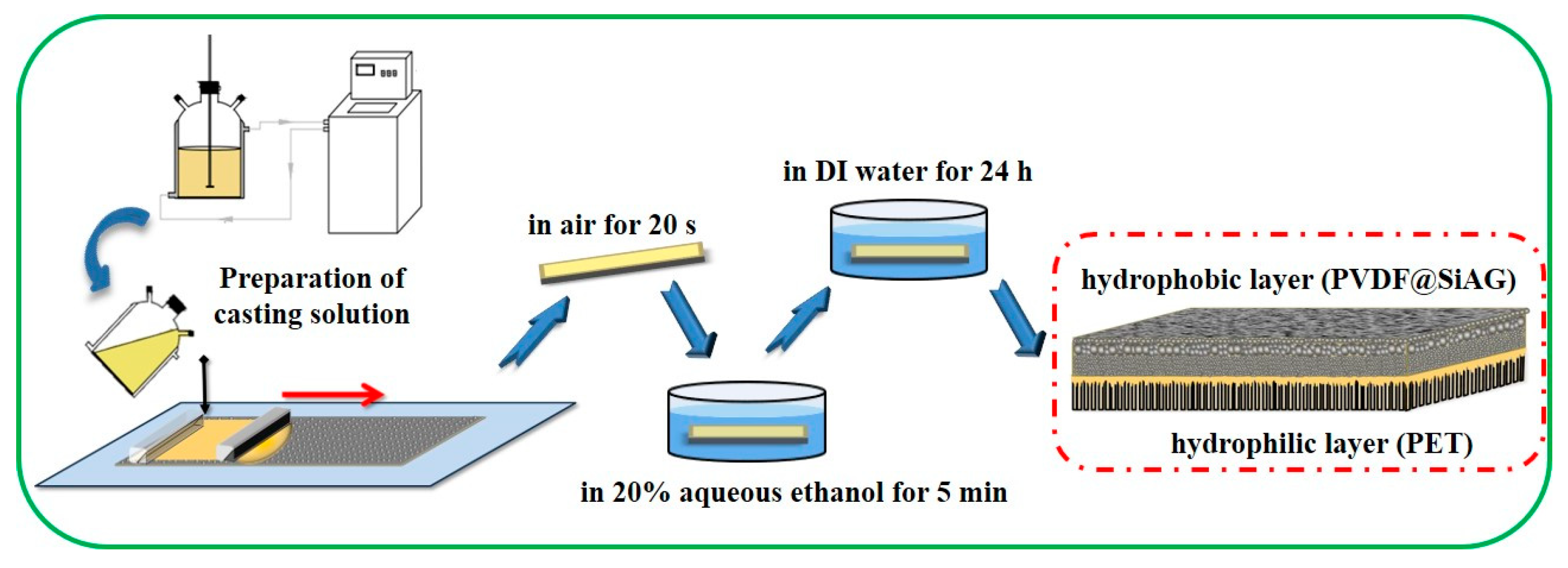
As shown in
Figure 1, the PVDF@SiAG/PET membranes with low thermal conductivity were prepared based on NIPS method. The casting solution was prepared by mixing LiCl, AC and DMA for 1 h, then a series of mass ratios of SiAG were added as listed in
Table 1. Thereafter, the PVDF powder was added and stirred for 2 h in a water bath at 60 ℃ to form a uniform casting solution. After standing for 12 h at room temperature for defoaming, the mixing solution was cast onto the surface of PET nuclear-track membranes (as the sub-layer) with a wet-thickness of 100 μm. After exposed in air for 20 s, the as-prepared composite membrane was immersed in 20% aqueous ethanol solution for 5 min, and then transferred into DI water for 24 h immersion. Finally, the PVDF@SiAG/PET hydrophobic/hydrophilic membranes were obtained, and these membranes were abbreviated as M-X, where X hereinafter refers to the corresponding mass ratio of SiAG to PVDF in the composite membranes. As references, the PVDF membranes without SiAG or PET sub-layer were also prepared [
13].
2.3. Structural characterization
A scanning electron microscope (SEM, Phenom Pure, Netherlands Phenom-World Ltd) was used to observe the top-surface of the membranes. The cross-sectional surface of the membranes was prepared by liquid nitrogen fracturing. Then, these samples were covered with sputtered gold using an Ion Sputtering device (SBC-12, KYKY Technology Co., Ltd.) for cross-sectional observation. A Tecnai G2 F-20 analyzer (FEI Company) was used for energy spectrum analysis, aiming to analyzing the Si distribution on the membrane surface.
The hydrophobicity of the membranes was characterized by IL 4200 Contact Angle Goniometer with Drop shape analysis (DSA100, KRÜSS Scientific). The average pore size, pore size distribution and air permeability of the membranes were characterized by a Capillary Flow Pyrometry (POROLUX 1000, Porometer Instrument Co., Ltd.). The porosity of the membranes was determined by gravimetric method. The dry membrane sample (md) was cut into a circular with a diameter of 25 mm, and its average thickness (h) was measured using a spiral micrometer (Shanghai Tool Works Co., Ltd.). Then, the sample was immersed in the Porefil
® infiltration solution for 12 h. After absorbing the residual infiltration solution on the surface with using filter paper, one can obtain the weight of the wet membranes (m
w). Then, the porosity (ω, %) was calculated according to Equation (1):
Where ρ is the profile density of the infiltration solution (1.86 g·cm-3); A is the membranes area (cm2).
2.4. Thermal conductivity test
The thermal conductivity of the membranes was measured using a thermal constant analyzer (Hot Disk TPS2500, Kegonas). The relationship between porosity and thermal conductivity is shown in Equation (2):
where λ (W·mK
-1) is the total thermal conductivity of the membranes; λ
v and λ
m are the thermal conductivity from the void (air or water vapor) and the bulk materials in the membranes, respectively. Based on Equation (3), λ
m is calculated by the volume fractions of PVDF to SiAG:
where λ
PVDF and λ
SiAG are the thermal conductivity of PVDF polymer and SiAG particles, respectively. P
PVDF and P
SiAG are the volume fractions of PVDF polymer and SiAG particles in the membranes, respectively.
2.5. Batch test of the DCMD
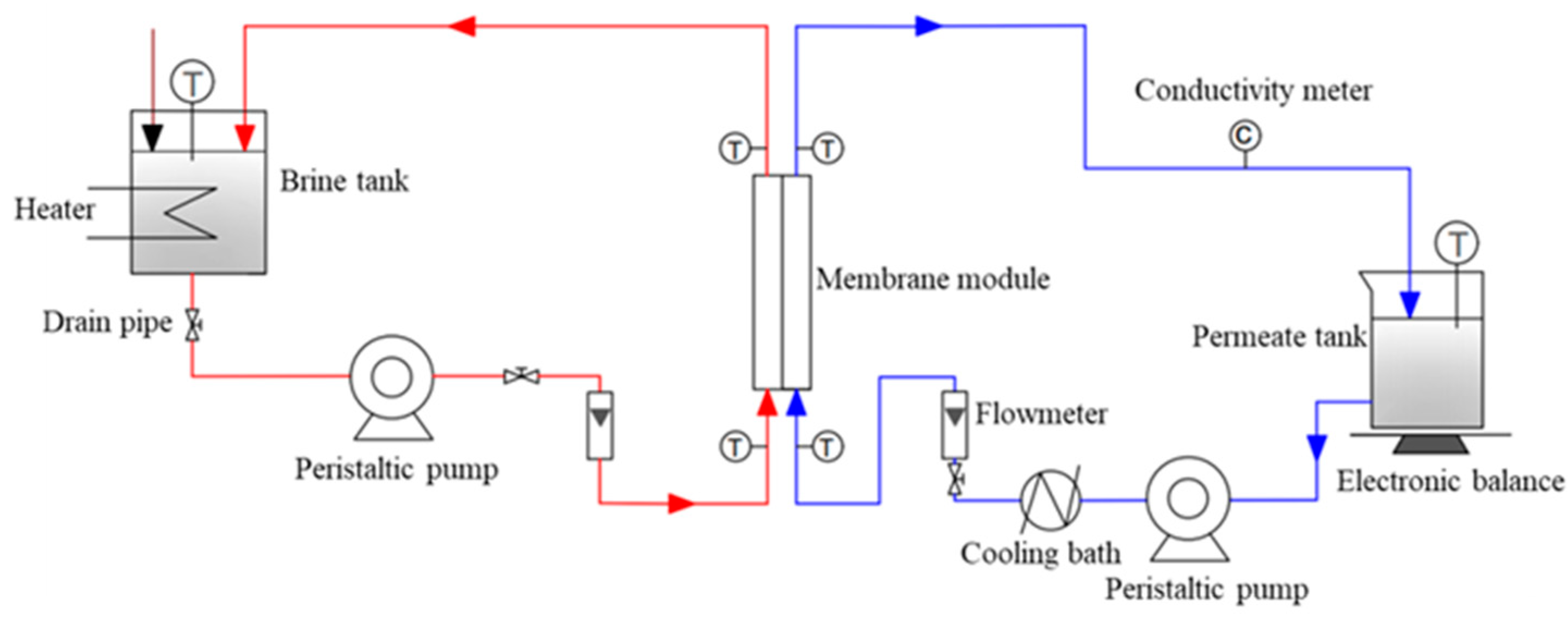
The separation performance of DCMD test was studied by using 3.5 wt.% NaCl solution as feed liquid.
Figure 2 illustrates the experimental instrument for the DCMD test. The feed liquid in a brine tank was heated up to 65°C, and the permeation temperature was controlled to 20°C. The peristaltic pump was running with a feed flow of 35 L·h
-1. The feed liquid from the brine tank went through the membrane’s module with effective membranes area of 72 cm
2. In the DCMD test, the water vapor in the feed liquid was transferred through the pores of the membranes, and then was cooled down and collected in the permeate tank [
14]. At the same time, the permeable liquid mass with the corresponding total dissolved solid (TDS) were measured at regular intervals. The permeation flux (J
w, kg·m
-2·h
-1) was calculated based on Equation (4):
where ∆w is the mass of the permeate (kg); A is the effective membranes area (m
2); ∆t is the distillate collection time (h).
Rejection rate (%) of NaCl solution was calculated based on Equation (5):
where C
f is the feed liquid concentration (mg·L
-1); C
p is the permeate concentration (mg·L
-1).
Latent heat of vaporization (H
L,W·m
-2) in the heat transfer process of the DCMD was calculated based on Equation (6):
where J
w is the permeation flux of water (kg·m
-2·h
-1); r= 2.3455×10⁶ J·kg
-1 is the heat of water vaporization of water (J·kg
-1).
Thermal-conductivity (H
C,W·m
-2) of the membranes was calculated f based on Equation (7):
where λ is the thermal conductivity of the membranes (W·m
–1·K
–1); l is the membranes thickness (m); T
fi and T
fo are the inlet and outlet temperatures of the liquid feed, respectively, T
pi and T
po are the inlet and outlet temperatures of the permeate, respectively. The temperature polarization was ignored in the calculation of H
C. The thermal efficiency (η, %) in the DCMD test was calculated based on Equation (8):
3. Results and discussion
3.1. Characterization of the PVDF@SiAG/PET membranes
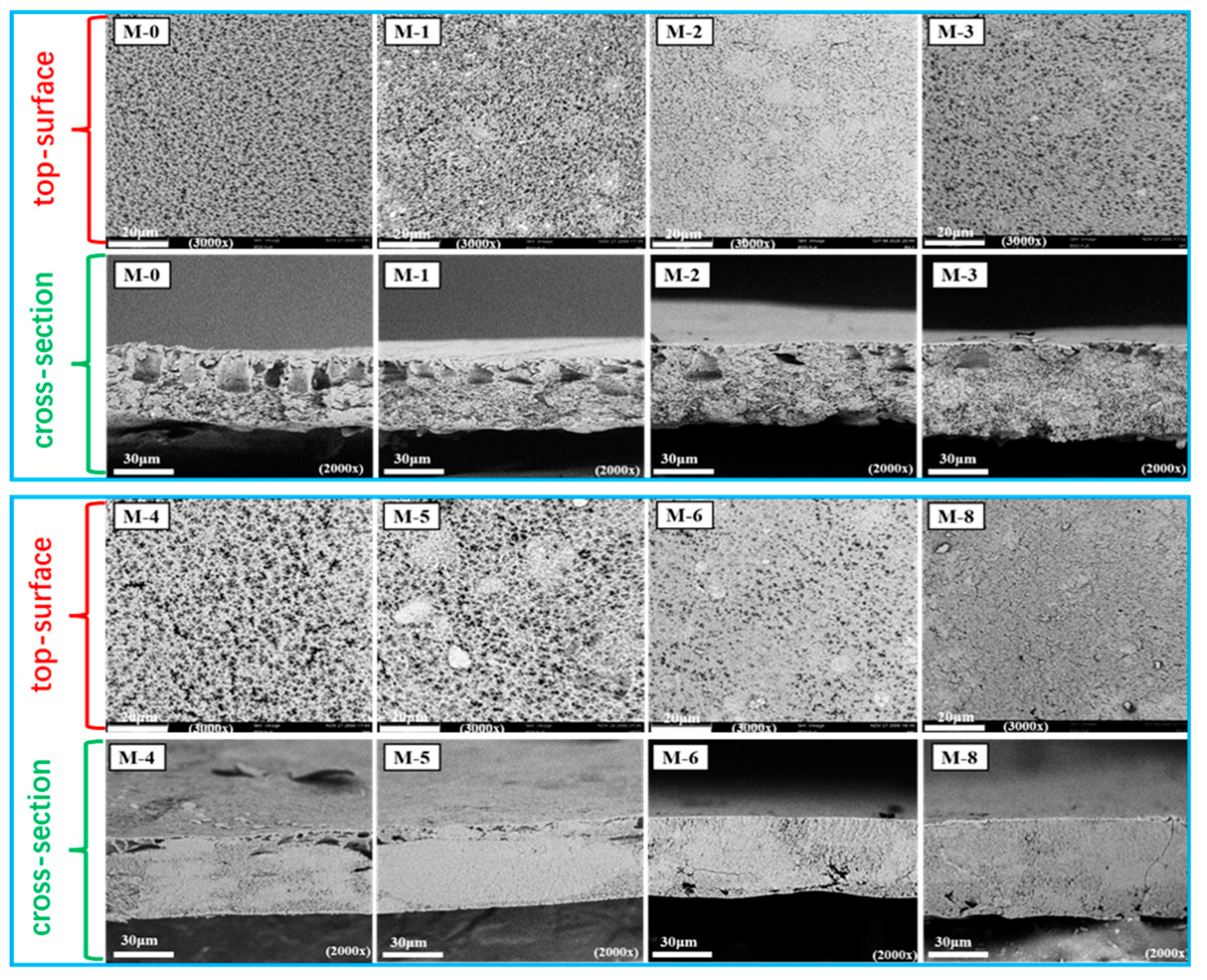
Figure 3 displays the top-surficial SEM images of the PVDF@SiAG/PET composite membrane. The M-0 displays the rather uniform pores over the top-surface. After adding SiAG, the top-surface SEM images of the membranes exhibit lumpy particles with low homogeneity. Furthermore, the distribution of SiAG particles of the M-1, M-2, M-3 and M-4 are relatively homogeneous with low adding amount. However, the SiAG particles on the surface of the M-5, M-6, and M-8 are agglomerated. Notably, M-0 without SiAG displays a typical finger-like pores throughout the spongy membrane, which can be also observed in the cross-sectional image. As more SiAG is added, the finger-like pores gradually disappear. When the R
SiAG exceeds 0.5, the sponge-like membrane becomes much dense with the vanishing finger-like pores. Thus, the adding amount of SiAG nanoparticles determines the change of membrane’s structure. This is because that SiAG nanoparticles served as the nucleating agent during the NIPS process, which speeded up the phase transition by increasing crystallization rate of PVDF polymer.
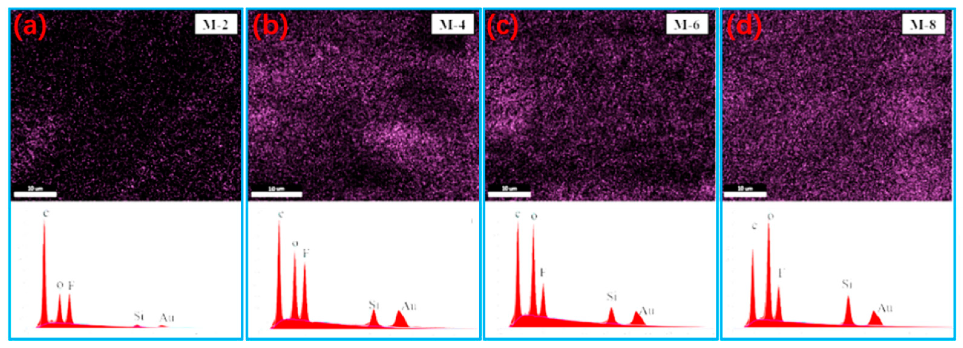
As seen in
Figure 4, the distribution variation of Si element with various contents in the membranes are visible by using energy spectrum analysis. SiAG particles are evenly distributed throughout the membranes’ surface, and the silicon content are detected to be 3.26 atom.% for M-2, 8.78 atom.% for M-4, 10.3 atom.% for M-6, and 14.62 atom.% for M-8, respectively. This agrees with the trend induced by increasing SiAG amount . However, the excessive SiAG nanoparticles are trapped in the PVDF polymer matrix, resulting in the decrease in the average pore size, as seen in
Figure 3. As a result, the inhomogeneous structure in the PVDF top-layer would deteriorate the structural stability and vapor permeability [
15].
To study the thermal stability of the composite membrane, the thermogravimetric analysis for the PVDF/SiAG and bare PVDF is contrastively displayed in Figure S2. The thermogravimetric curves demonstrate that the mass of the bare PVDF membrane begins to decrease when the temperature is above 366°C, whereas the mass of the PVDF/SiAG without PES begins to decrease at above 459°C, indicating that the addition of the inorganic SiAG aerogel is benefitial to enhancing the thermal stability of the PVDF membrane [
16].
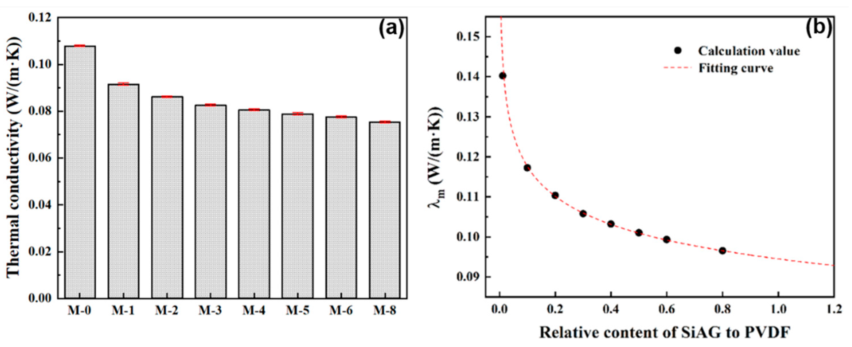
In this study, the thermal conductivity of the PVDF@SiAG/PET composite membranes was measured using a thermal constant analyzer. As shown in
Figure 5a, the thermal conductivity of PVDF@SiAG/PET membrane is decreased with increasing R
SiAG. Thus, M-0 displays the maximum thermal conductivity of 0.1079 W·m
-1·K
-1. In contrast, thermal conductivity is 0.0754 Wm
-1·K
-1 in the M-0.8, which is reduced by 30.12% when comparing with M-0. This indicates that SiAG with intrinsic thermal conductivity of 0.01 W·m
-1·K
-1 can substantially reduce the thermal conductivity of the PVDF [
17]. Moreover, as shown in
Figure 5b, the calculated λ
m values fit well with the theoretical curves with a correlation coefficient R
2 = 0.9998. Furthermore, the λ
m is reduced by 30.44% when the R
SiAG was increased from 0.0 to 0.8. Therefore, the findings show a favorable correlation between the SiAG addition and the declining in thermal conductivity of PVDF@SiAG/PET membranes.
Furthermore, the pore size distribution in the PVDF@SiAG/PET membrane and the corresponding average pore size of the PVDF@SiAG/PET membranes are depicted in
Figure 6. The average pore size is gradually increased from M-0 to M-4, while the average pore size rapidly drops when the R
SiAG is above 0.5. As discussed above, The SiAG addition leads to the formation of loose structure of the membrane.
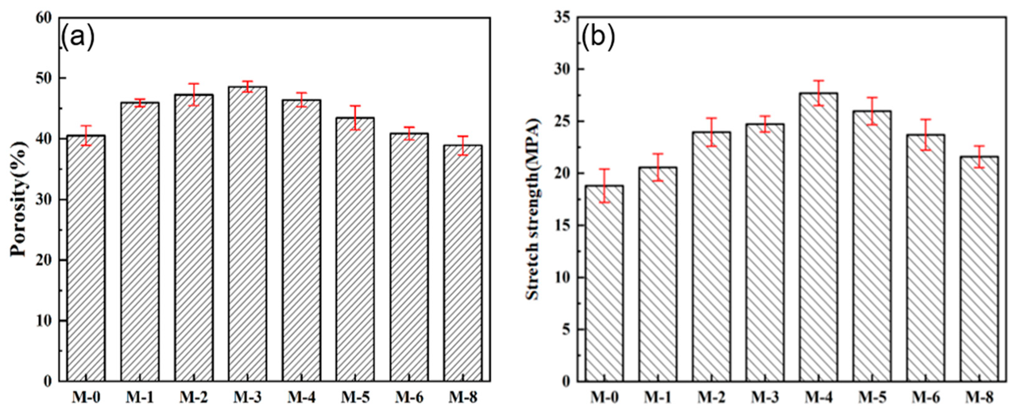
In the practical application, the porous structure and mechanical strength of the membrane are key parameters for DCMD performance, in terms of running stability.
Figure 7a shows the effect of SiAG content on membrane porosity. With the increase in SiO
2 aerogel addition, the porosity of the composite membrane increases from 39.52% for M-0 to 45.60% for M-4, because the low amount of SiAG leads to the formation of loose structure, and thus the internal connectivity of pores is enhanced. However, the excessive SiAG nanoparticles were encapsulated in the PVDF polymer matrix, which results in decrease in the average pore size and porosity, which was consistent with the change in surface morphology (see
Figure 3). As further increasing SiAG content, the porosity is reduced from 41.41% for M-5 to 36.60% for M-8. Hence, the results confirm that the average pore size and its distribution of the PVDF@SiAG/PET membrane can be adjusted by adding SiAG nanoparticles [
18].
As shown in
Figure 7b, the tensile strength of PVDF@SiAG/PET membranes initially is increased from 19.79 MPa for M-0 to 27.78 MPa for M-4, and then decreased to 21.58 MPa for M-8. This is because that SiAG ceramic fillers can be used as strength-enhancing fillers. Moreover, the adding SiAG can serve as the cross-linking points to physically join the polymeric chains, which can distribute the external load evenly and reduce the possibility of fracture of membrane materials. Therefore, the linked PVDF chains improves mechanical strength. However, the excessive addition of of SiAG can form microporous defects during the NIPS process. Additionally, the cracking points are likely to appear at the microporous defects when applying tensile external force, which reduces the tensile strength of PVDF@SiAG/PET membranes. In conclusion, R
SiAG = 0.4 is considered as the proper adding amount to increase the membrane's mechanical strength [
19].
3.2. Effect of PVDF@SiAG/PET membranes on DCMD
Figure S3 shows the effect of SiAG addition on the contact angle of the composite membranes. The contact angle still increases from 91.68° for the M-0 to 122.81° for the M-8 as increasing SiAG content. This is because that the hydrophobic SiAG particles (the static contact angle of modified SiO
2 is more than 150°) loaded on the PVDF surface [
20].
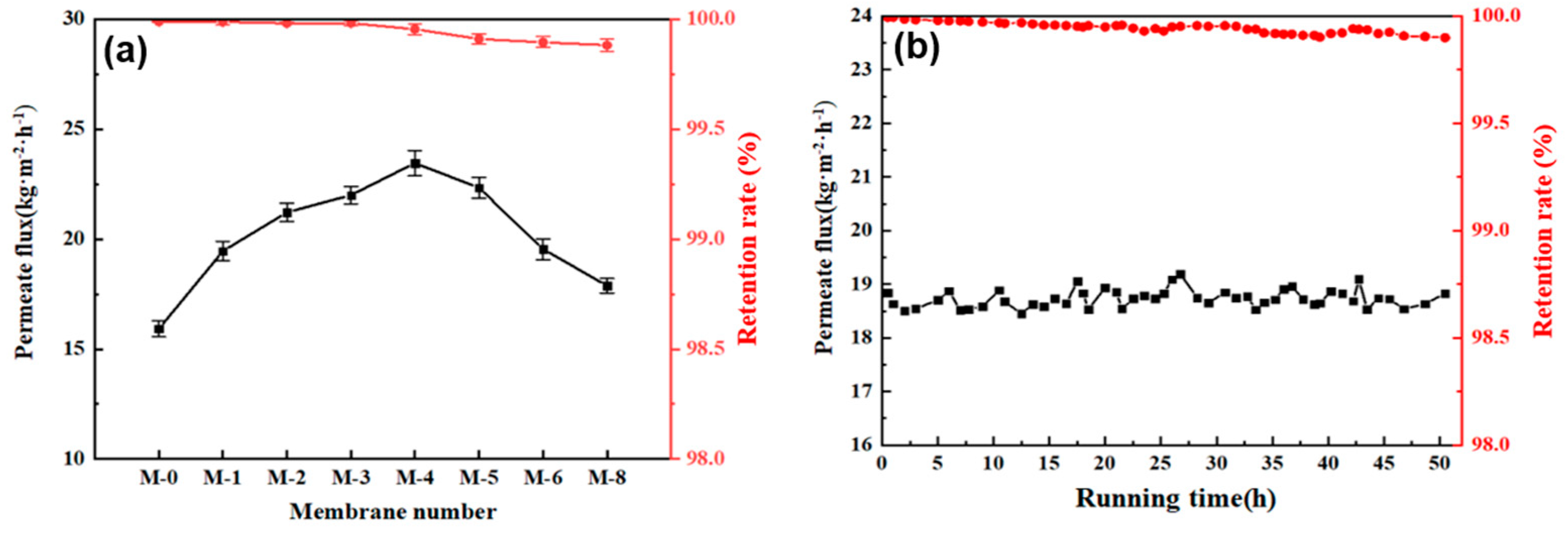
In the DCMD test, the flow rate of 35 L/h was set on both the feed side and the permeate side, and with the flux temperature of feed side and permeate side was controlled at 65°C and 20°C, respectively. Herein, the separation performance of the PVDF@SiAG/PET composite membrane was examined in the DCMD process. According to
Figure 8a, the maximum permeate flux (23.462 kg·m
-2·h
-1) was achieved in the M-4. In contrast to the M-0, the initial addition of SiAG particles significantly increase the flux, and this is because that the addition of silica aerogel results in the loosen structure of the composite membrane. However, the excessive addition of SiAG leads to decrease in the flux, and this is ascribed to the decrease in average pore size and elevated vapor transfer resistance induced by the denser membrane structure.
The stable running time experiment was conducted by using M-4 membrane, and the experimental conditions were 70°C for feed side and 20°C for permeate side flow rates. As shown in
Figure 8b, the permeate flux remained stable after about 50 h operation, ranging between 18.514 kg·m
-2·h
-1 and 19.136 kg·m
-2·h
-1. This finding demonstrates that the addition of hydrophobic low thermal conductivity materials (SiAG) could significantly enhance the permeation rate and separation performance of the PVDF@SiAG/PET composite membranes [
21].
Moreover, M-0, M-1, M-2 and M-3 possess the retention rates above 99.99%, whereas the retention rate of M-4, M-5, M-6, M-7 and M-8 is between 99.93% and 99.88%, as shown In
Figure 8b. It is most likely as a result of the partial loss of SIAG particles induced by the feed fluid's scouring on the membrane surface. However, the spongy structure and pore size of the membrane are destroyed by excessive addition of the SiAG. Thus, the M-4 membrane preserves the high-performance stability over 50 h, which should be preferably chosen due to the high permeate flux and high retention rate [
22].
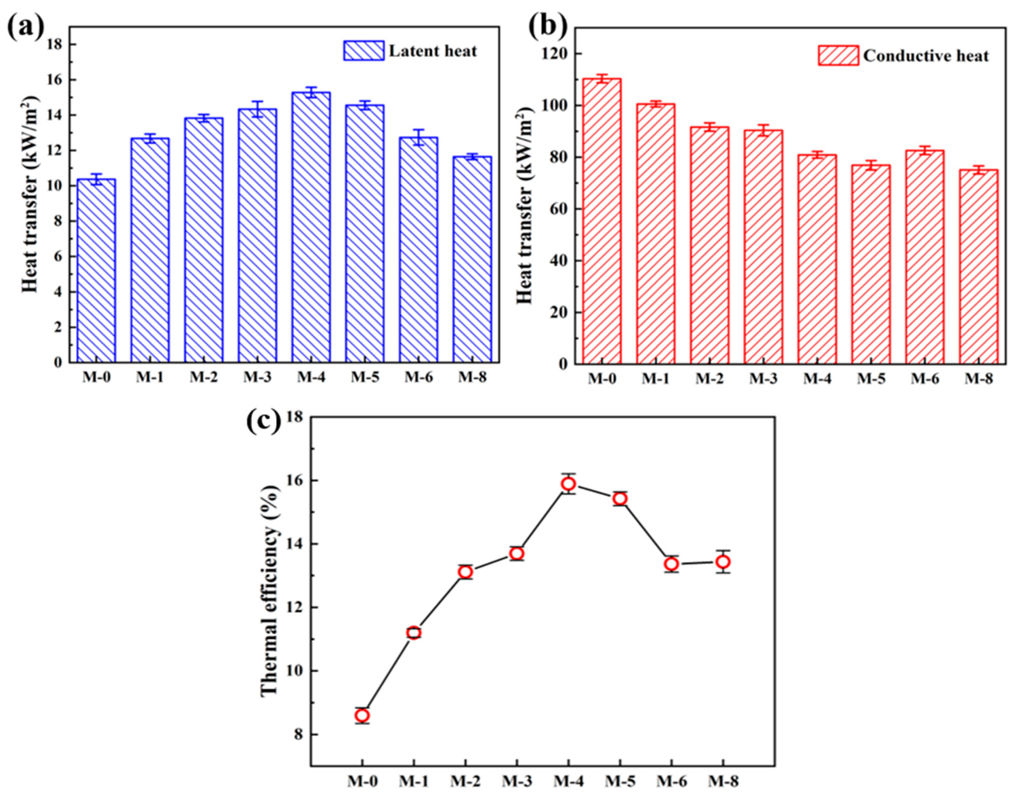
Figure 9a&b depicts the latent heat of vaporization and heat transmission across the composite membranes, respectively. The latent heat of vaporization for M-0 is 10.37 kW·m
-2, while the maximum latent heat of 15.28 kW·m
-2 is found in the M-4. In
Figure 9b, the highest conductive heat of 110.30 kW·m
-2 is found in the M-0, and the conduction heat is gradually with further adding SiAG. Notably, the PVDF@SiAG/PET membrane with low thermal conductivity can reduce temperature polarization effect [
23] and heat loss during MD test. In addition, the high temperature gradient across the composite membrane with low thermal conductivity can lead to a greater temperature difference between the permeation side and feed side, which obviously increases the mass transfer driving force.
As shown in
Figure 9c, the thermal efficiency in the DCMD is defined as the ratio of the latent heat of vaporization to the sum of the latent heat of vaporization and the conduction heat across the membrane. In this study, the M-0 displays the lowest thermal efficiency (8.59%), and the SiAG addition greatly enhance the thermal efficiency. Moreover, the M-4 possesses the highest thermal efficiency (15.89%). The findings demonstrate that the latent heat and the conduction heat can determine change of the thermal efficiency, and this is ascribed to modification of PVDF membrane by using SiAG. Importantly, the addition of SiAG enhances the latent heat of vaporization by increasing the average pore size, which in turn increases the permeate flux in the DCMD test.
Table 2 summarizes recent research on the performance of low thermal conductivity membranes, and it is found that the model pore size prepared in this study is smaller and the flux is higher. Therefore, the PVDF@SiAG/PET membrane with R
SiAG = 0.4 display a significant potential for the water treatment in term of the enhanced energy saving and thermal efficiency [
24].
4. Conclusion
In this study, a novel functionalized modification method for PVDF@SiAG/PET composite membranes were studied, aiming to reducing thermal conductivity of MD membrane. The experimental results show that the loosened membrane and improved thermal stability were achieved with the SiAG addition. The proper addition of SiAG (RSiAG = 0.4) promotes the crystallization rate of PVDF chains, resulting in an increase in pore size and porosity, hydrophobicity, mechanical strength as well as thermal resistance. In the DCMD batch tests, the permeate flux of M-4 reaches the maximum value of 23.462 kg·m-2·h-1, which was 45.5% higher than that of M-0 without adding SiAG, and the DCMD was stably running over 50 h. Therefore, the applied performance of PVDF@SiAG/PET membranes is improved comprehensively by SiAG modification.
Author Contributions
Conceptualization, J.X.; methodology, S.W.; software, G.T.; validation, X.W. and N.C.; investigation, L.Z.; data curation, P.C.; writing—original draft preparation, S.W.; writing—review and editing, N.T.; supervision, J.Z. All authors have read and agreed to the published version of the manuscript.
Funding
This work was supported by the National Natural Science Foundation of China (U20A20148), National key research and development program (2022YFC2904005), Tianjin Science and Technology Committee Development Project (21ZYQCSY00050), Tianjin Key Laboratory of Brine Chemical Engineering and Resource Eco-utilization (No. BCERE202105), Yangtze Scholars and Innovative Research Team in University (IRT-17R81), and the Innovative Training/Entrepreneurial Program for Undergraduate (No. 202310057060) and Innovative Research Team of Tianjin Municipal Education Commission (TD13-5008).
Institutional Review Board Statement
Not applicable.
Data Availability Statement
The data presented in this study are available on request from the corresponding author.
Conflicts of Interest
The authors declare no conflict of interest.
References
- Grasso, G.; Galiano, F.; Yoo, M. J.; Mancuso, R.; Park, H. B.; Gabriele, B.; Figoli, A.; Drioli, E., Development of graphene-PVDF composite membranes for membrane distillation. Journal of Membrane Science 2020, 604. [CrossRef]
- Kiss, A. A.; Kattan Readi, O. M., An industrial perspective on membrane distillation processes. Journal of Chemical Technology & Biotechnology 2018, 93 (8), 2047-2055. [CrossRef]
- Shirazi, M. M. A.; Dumée, L. F., Membrane distillation for sustainable wastewater treatment. Journal of Water Process Engineering 2022, 47. [CrossRef]
- Chen, L.; Wu, B., Research Progress in Computational Fluid Dynamics Simulations of Membrane Distillation Processes: A Review. Membranes (Basel) 2021, 11 (7). [CrossRef]
- Bonyadi, S.; Chung, T. S., Flux enhancement in membrane distillation by fabrication of dual layer hydrophilic–hydrophobic hollow fiber membranes. Journal of Membrane Science 2007, 306 (1-2), 134-146. [CrossRef]
- Alkhudhiri, A.; Darwish, N.; Hilal, N., Membrane distillation: A comprehensive review. Desalination 2012, 287, 2-18. [CrossRef]
- Yang, C.; Li, X.-M.; Gilron, J.; Kong, D.-f.; Yin, Y.; Oren, Y.; Linder, C.; He, T., CF4 plasma-modified superhydrophobic PVDF membranes for direct contact membrane distillation. Journal of Membrane Science 2014, 456, 155-161. [CrossRef]
- Li, K.; Wang, K.; Zhang, Y.; Liu, H.; Wang, J., A polyvinylidene fluoride (PVDF)–silica aerogel (SiAG) insulating membrane for improvement of thermal efficiency during membrane distillation. Journal of Membrane Science 2020, 597. [CrossRef]
- Li, Z.; Peng, Y.; Dong, Y.; Fan, H.; Chen, P.; Qiu, L.; Jiang, Q., Effects of thermal efficiency in DCMD and the preparation of membranes with low thermal conductivity. Applied Surface Science 2014, 317, 338-349. [CrossRef]
- Zhao, L.; Wu, C.; Lu, X.; Ng, D.; Truong, Y. B.; Zhang, J.; Xie, Z., Theoretical guidance for fabricating higher flux hydrophobic/hydrophilic dual-layer membranes for direct contact membrane distillation. Journal of Membrane Science 2020, 596. [CrossRef]
- Zheng, L.; Wang, J.; Yu, D.; Zhang, Y.; Wei, Y., Preparation of PVDF-CTFE hydrophobic membrane by non-solvent induced phase inversion: Relation between polymorphism and phase inversion. Journal of Membrane Science 2018, 550, 480-491. [CrossRef]
- Ashoor, B. B.; Mansour, S.; Giwa, A.; Dufour, V.; Hasan, S. W., Principles and applications of direct contact membrane distillation (DCMD): A comprehensive review. Desalination 2016, 398, 222-246. [CrossRef]
- Lü, X.; Wang, X.; Guo, L.; Zhang, Q.; Guo, X.; Li, L., Preparation of PU modified PVDF antifouling membrane and its hydrophilic performance. Journal of Membrane Science 2016, 520, 933-940. [CrossRef]
- Ke, H.; Feldman, E.; Guzman, P.; Cole, J.; Wei, Q.; Chu, B.; Alkhudhiri, A.; Alrasheed, R.; Hsiao, B. S., Electrospun polystyrene nanofibrous membranes for direct contact membrane distillation. Journal of Membrane Science 2016, 515, 86-97. [CrossRef]
- Lim, S. J.; Shin, I. H., Graft copolymerization of GMA and EDMA on PVDF to hydrophilic surface modification by electron beam irradiation. Nuclear Engineering and Technology 2020, 52 (2), 373-380. [CrossRef]
- Abed, A.; Bouazizi, N.; Giraud, S.; El Achari, A.; Campagne, C.; Thoumire, O.; El Moznine, R.; Cherkaoui, O.; Vieillard, J.; Azzouz, A., Polyester-supported Chitosan-Poly(vinylidene fluoride)-Inorganic-Oxide-Nanoparticles Composites with Improved Flame Retardancy and Thermal Stability. Chinese Journal of Polymer Science 2019, 38 (1), 84-91. [CrossRef]
- Zhang, L.-Z.; Su, Q.-W., Performance manipulations of a composite membrane of low thermal conductivity for seawater desalination. Chemical Engineering Science 2018, 192, 61-73. [CrossRef]
- Chen, G.-E.; Sun, W.-G.; Kong, Y.-F.; Wu, Q.; Sun, L.; Yu, J.; Xu, Z.-L., Hydrophilic Modification of PVDF Microfiltration Membrane with Poly (Ethylene Glycol) Dimethacrylate through Surface Polymerization. Polymer-Plastics Technology and Engineering 2017, 57 (2), 108-117. [CrossRef]
- Lu, Y.; Ma, Y.; Yang, T.; Guo, J., Hydrophilic modification of PVDF membranes by in situ synthesis of nano-Ag with nano-ZrO2. Green Processing and Synthesis 2021, 10 (1), 538-546.
- Hamzah, N.; Leo, C. P., Fouling prevention in the membrane distillation of phenolic-rich solution using superhydrophobic PVDF membrane incorporated with TiO2 nanoparticles. Separation and Purification Technology 2016, 167, 79-87. [CrossRef]
- Makanjuola, O.; Anis, S. F.; Hashaikeh, R., Enhancing DCMD vapor flux of PVDF-HFP membrane with hydrophilic silica fibers. Separation and Purification Technology 2021, 263. [CrossRef]
- Pagliero, M.; Bottino, A.; Comite, A.; Costa, C., Novel hydrophobic PVDF membranes prepared by nonsolvent induced phase separation for membrane distillation. Journal of Membrane Science 2020, 596. [CrossRef]
- Ravindra Babu, B.; Rastogi, N. K.; Raghavarao, K. S. M. S., Concentration and temperature polarization effects during osmotic membrane distillation. Journal of Membrane Science 2008, 322 (1), 146-153. [CrossRef]
- Zhang, J.; Kong, Y.; Shen, X., Polyvinylidene fluoride aerogel with high thermal stability and low thermal conductivity. Materials Letters 2019, 259, 126890. [CrossRef]
- Wu, R.; Tan, Y.; Meng, F.; Zhang, Y.; Huang, Y.-X., PVDF/MAF-4 composite membrane for high flux and scaling-resistant membrane distillation. Desalination 2022, 540. [CrossRef]
- Li, Z.; Cheng, B.; Ju, J.; Kang, W.; Liu, Y., Development of a novel multi-scale structured superhydrophobic nanofiber membrane with enhanced thermal efficiency and high flux for membrane distillation. Desalination 2021, 501. [CrossRef]
- Lee, D.; Woo, Y. C.; Park, K. H.; Phuntsho, S.; Tijing, L. D.; Yao, M.; Shim, W.-G.; Shon, H. K., Polyvinylidene fluoride phase design by two-dimensional boron nitride enables enhanced performance and stability for seawater desalination. Journal of Membrane Science 2020, 598. [CrossRef]
- Mohd Yatim, N. S.; Abd. Karim, K.; Ooi, B. S., Nodular structure and crystallinity of poly(vinylidene fluoride) membranes: Impact on the performance of direct-contact membrane distillation for nutrient isolation. Journal of Applied Polymer Science 2018, 135 (44). [CrossRef]
- Wae AbdulKadir, W. A. F.; Ahmad, A. L.; Ooi, B. S., Hydrophobic PVDF-HNT membrane for oxytetracycline removal via DCMD: The influence of fabrication parameters on permeability, selectivity and antifouling properties. Journal of Water Process Engineering 2022, 49. [CrossRef]
- Woo, Y. C.; Yao, M.; Shim, W.-G.; Kim, Y.; Tijing, L. D.; Jung, B.; Kim, S.-H.; Shon, H. K., Co-axially electrospun superhydrophobic nanofiber membranes with 3D-hierarchically structured surface for desalination by long-term membrane distillation. Journal of Membrane Science 2021, 623. [CrossRef]
- Li, H.; Liu, H.; Shi, W.; Zhang, H.; Zhou, R.; Qin, X., Preparation of hydrophobic zeolitic imidazolate framework-71 (ZIF-71)/PVDF hollow fiber composite membrane for membrane distillation through dilute solution coating. Separation and Purification Technology 2020, 251.
- Cheng, D.; Zhao, L.; Li, N.; Smith, S. J. D.; Wu, D.; Zhang, J.; Ng, D.; Wu, C.; Martinez, M. R.; Batten, M. P.; Xie, Z., Aluminum fumarate MOF/PVDF hollow fiber membrane for enhancement of water flux and thermal efficiency in direct contact membrane distillation. Journal of Membrane Science 2019, 588. [CrossRef]
- Rahmaniyan, B.; Mohammadi, T.; Tofighy, M. A., Development of high flux PVDF/modified TNTs membrane with improved properties for desalination by vacuum membrane distillation. Journal of Environmental Chemical Engineering 2021, 9 (6). [CrossRef]
|
Disclaimer/Publisher’s Note: The statements, opinions and data contained in all publications are solely those of the individual author(s) and contributor(s) and not of MDPI and/or the editor(s). MDPI and/or the editor(s) disclaim responsibility for any injury to people or property resulting from any ideas, methods, instructions or products referred to in the content. |
© 2023 by the authors. Licensee MDPI, Basel, Switzerland. This article is an open access article distributed under the terms and conditions of the Creative Commons Attribution (CC BY) license (http://creativecommons.org/licenses/by/4.0/).
