1. Introduction
High entropy alloy (HEA) is a new type of alloy, which has attracted great attention in the past decades because of its excellent physical and chemical properties, and is considered as a new type of structural material[1-3]. Extensive research has evaluated the radiation resistance of HEAs, focusing on the comparison of phase stability and dimensional stability between HEAs and traditional alloys[4-6]. For example, CoCrFeNiMn HEA with a single FCC phase shows enhanced radiation resistance by inhibiting void formation, and has 40 times higher expansion resistance than nickel at high temperature[
7]. Under the irradiation of 723 K, the He bubble size (4.0 nm) formed in CoCrFeNiMn is obviously smaller than that in 304 stainless steel (5.5 nm)[
8]. With the increase of Al content, the structure of Al
xCoCrFeNi HEAs changes from FCC to FCC+BCC, and then to BCC. Compared with conventional nuclear materials, Al
xCoCrFeNi HEAs shows excellent structural stability and volume expansion resistance[
9]. Meanwhile, researchers in HEAs turn to develop multiphase HEAs to improve its radiation tolerance and mechanical properties, but this usually leads to poor castability[
10].
In recent years, eutectic high-entropy alloys (EHEAs) have been studied more and more widely. In addition to being a novel method for obtaining composite structures in HEAs, eutectic alloys are also considered good candidates for superalloys because the eutectic solidification microstructure has the following characteristics: 1) the microstructure is close to equilibrium, that is, it can resist changes at the same high temperature as its reaction temperature; 2) low-energy phase boundaries; 3) controllable microstructures; 4) high fracture strength; 5) the defect structure is stable; 6) good high temperature creep resistance[
11]. In addition, eutectic alloy also has good castability. the AlCoCrFeNi
2.1 EHEA has attracted much attention because of its good strength, ductility and excellent thermodynamic properties[
11]. The atomic scale irradiation response of AlCoCrFeNi
2.1, which consists of face-centered cubic (FCC) phase and B2 phase, has been systematically studied by Pang et al[
12]. The results show that, compared with B2 structure, disordered FCC phase has stronger ability to inhibit the nucleation and growth of He bubbles. Another eutectic component that has received more attention is CoCrFeNiNb
x EHEA. He et al.[
13] reported that CoCrFeNiNb
x EHEAs with attenuated layered structure maintained good strength and ductility, and the layered structure was stable below 750℃, but rapidly coarsened at 900℃. The deformation mechanism of CoCrFeNiNb
x during high pressure torsional deformation was studied by nanoindentation experiment.[
14] It was suggested that the high pressure torsion process could obtain EHEAs of ultra-high strength while preserving the excellent plasticity of the alloy at room temperature.
At present, there are few studies on the evolution of mechanical properties of EHEAs after irradiation. Meanwhile, most studies focus on the influence of composition on radiation-induced expansion and radiation damage, while the micro-changes of EHEAs induced by radiation, such as the evolution of helium bubbles, are rarely reported. In this study, the typical CoCrFeNiNb0.65 EHEA is selected, the main purpose is to determine the irradiation response of He+ ion irradiation, and some interesting phenomena are explained. In this study, the basic irradiation behavior of EHEA materials was studied, and the potential of this series of materials in extreme environment was deeply understood.
2. Materials and Methods
CoCrFeNiNb0.65 EHEAs prepared via arc melting 99.99% pure elemental constituents together in a high purity argon atmosphere. The ingots were inverted and melted repeatedly to ensure homogeneity and subsequently suck-casted into a water-cooled copper mold (45 mm). Then Φ5 mm cylindrical rods were cut into wafer samples with 2.0 mm thickness, and then mechanically polished to a mirror finish. Irradiation experiments were conducted in the 320 kV multidiscipline research platform for highly-charged ions (Institute of Modern Physics, Chinese Academy of Sciences, Lanzhou, China), at a pressure near or below 10−5 torr. The polished samples were irradiated with a 100 keV He+ ion beam, with ion fluences of 5.0×10¹⁷ ions/cm2, 1.0×10¹⁸ ions/cm2, and 2.0×10¹⁸ ions/cm2, respectively, at room temperature.
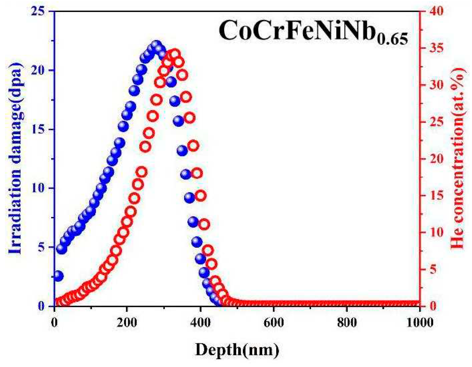
Figure 1 shows the results of ion distribution, radiation damage (displacement per atom or dpa) and He atom concentration increasing with depth calculated using the Ion Distribution and Quick Calculation of Damage mode in the SRIM (Stopping and Range of Ions in Matter) 2008 code[
15]. As shown in
Figure 1, when a large number of incident ions enter EHEAs, they form a spatial influence area instead of a specific path due to collision cascade. The total number of ions is 99,999, and the effective depth of ion influence is ~500 nm. The dpa is determined by the predicted vacancy concentrations of Co, Cr, Fe, Ni and Nb and the sum of recoil events in the range of ~500 nm from the surface. In addition, the number of atomic shifts reaches a peak at a depth of about 290 nm, which corresponds to the projection range of He
+ ions in CoCrFeNiNb
0.65 EHEAs. Under the influence of 5.0×10
17 ions /cm
2, the peak concentration of He atoms is about 22.0%.
The microstructures were characterized by X-ray diffraction (XRD) via a Philips PW 1050 diffractometer with Cu-Ka radiation operating at 45 keV, a 0.01 step size, and a 200 mA current for phase analysis with improved accuracy. The diffraction area of sample surface is 0.5 mm, and the scanning speed is 2°/min. Each sample was examined three times in different areas.
The microstructure and composition of the samples were analyzed by a scanning electron microscopy (SEM, HITACHI S-4800, Tokyo, Japan) at a working voltage of 20.0 kV and a working distance of 15.8 mm, with energy-dispersive X-ray spectroscopy (EDX, HORIBA X-Max, Kyoto, Japan). Transmission electron microscopy (TEM) observations were performed via an FEI Tecnai G2 microscope operating at 200 kV to investigate the microstructural evolution of the samples. The cross-sectional TEM samples were obtained via the gallium focused-ion beam (FIB, Helios Nanolab 600) lift-out technique on a ZEISS Auriga FIB-SEM workstation.
To investigate the ion irradiation-induced microstructural evolution of EHEAs, nanoindentation experiments were conducted on pristine and irradiated samples using an Agilent Technologies Nano Indenter G200 with a Berkovich diamond indenter at 20℃ after calibration on standard fused silicon. The loading rate was 0.05 mN/s, with a maximum loading of 20 mN.
3. Results
3.1. Microstructural Characterization
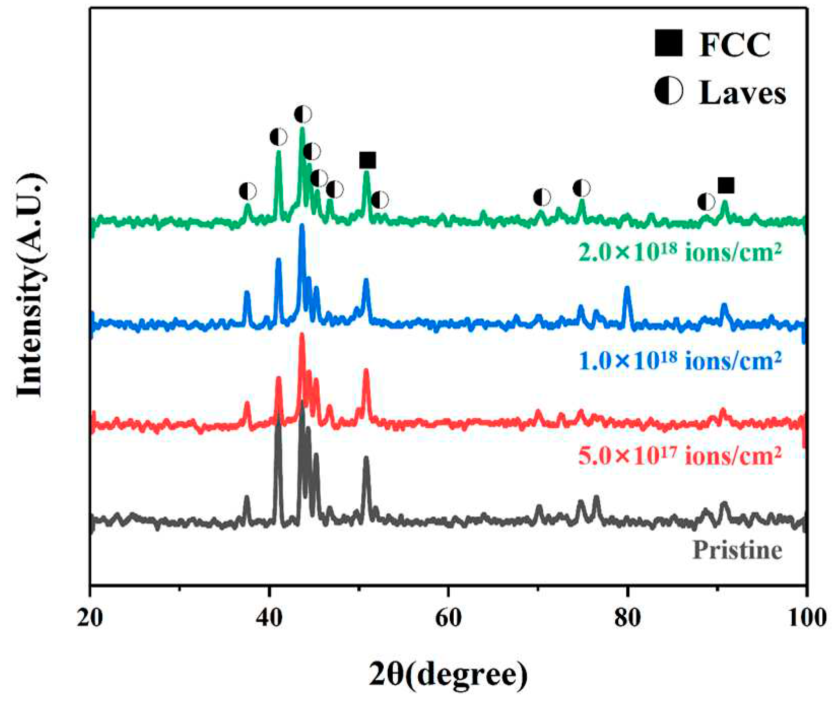
The XRD patterns of the pristine and irradiated CoCrFeNiNb
0.65 EHEA samples at different fluences are presented in
Figure 2. The results indicated that the alloys are composed of FCC and laves phases. And no obvious phase decomposition occurred under any irradiation condition, which is consistent with high configurational entropy playing a significant role in phase stability.
3.2. Surface Topography
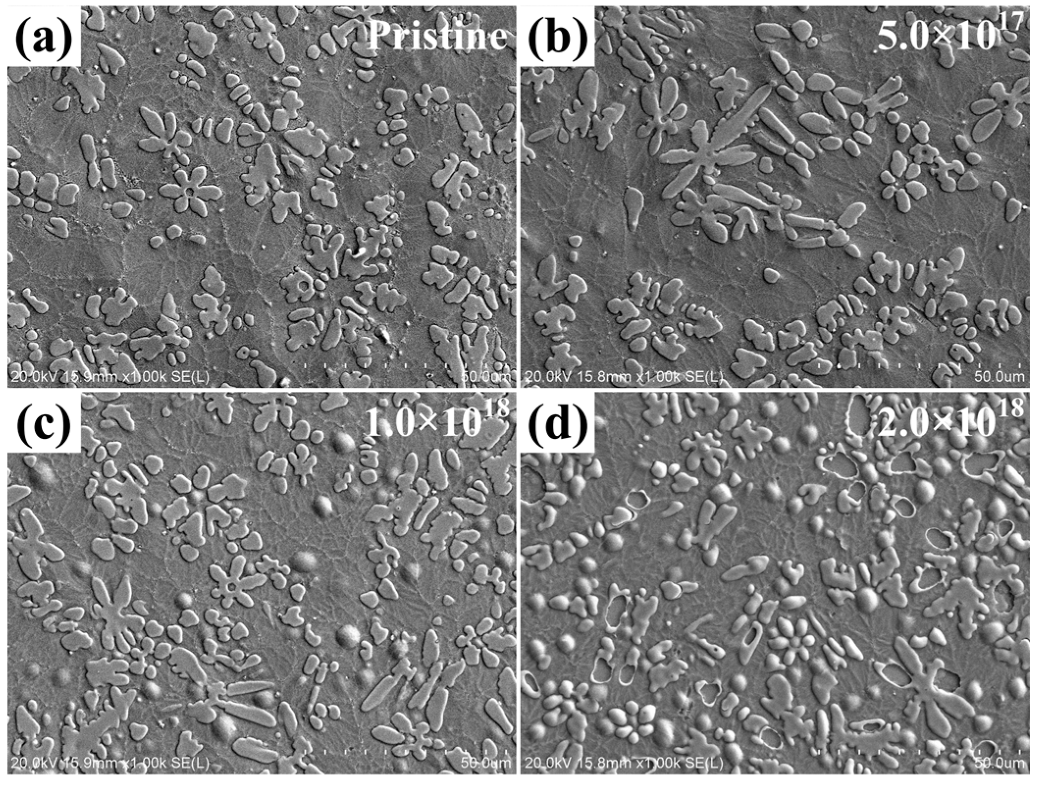
The SEM images reveal the surface morphology of pristine and irradiated CoCrFeNiNb
0.65 EHEAs at various fluences, as shown in
Figure 3a-d. According to the SEM results indicate the surface morphology of the samples is mainly composed of two phases, matrix phase and petal-like Nb-rich phase. The surface of the sample did not change significantly at the fluence of 5.0×10
17 ions/cm
2. As the ion fluence reaching 1.0×10
18 ions/cm
2, it is easy to find some obvious bubbles in the matrix phase region, which is due to the surface bubbling induced by He ion irradiation. However, when the ion fluence was as high as 2.0×10
18 ions/cm
2, the number of bubbles increased significantly. It should be noted that at this fluence, the Nb-rich phase also began to show large shedding, exposing the lower surface after peeling. This peeling phenomenon after irradiation is mainly due to the low energy and high fluence of He ions injected into the material, which have a relatively shallow incidence range due to the low incidence energy of ions, and the accumulated helium bubbles induced by high fluence He injection will gradually move to the surface, eventually leading to swelling and peeling of the surface, which also suggested that the degree of swelling varied between the two phases under the same irradiation condition.
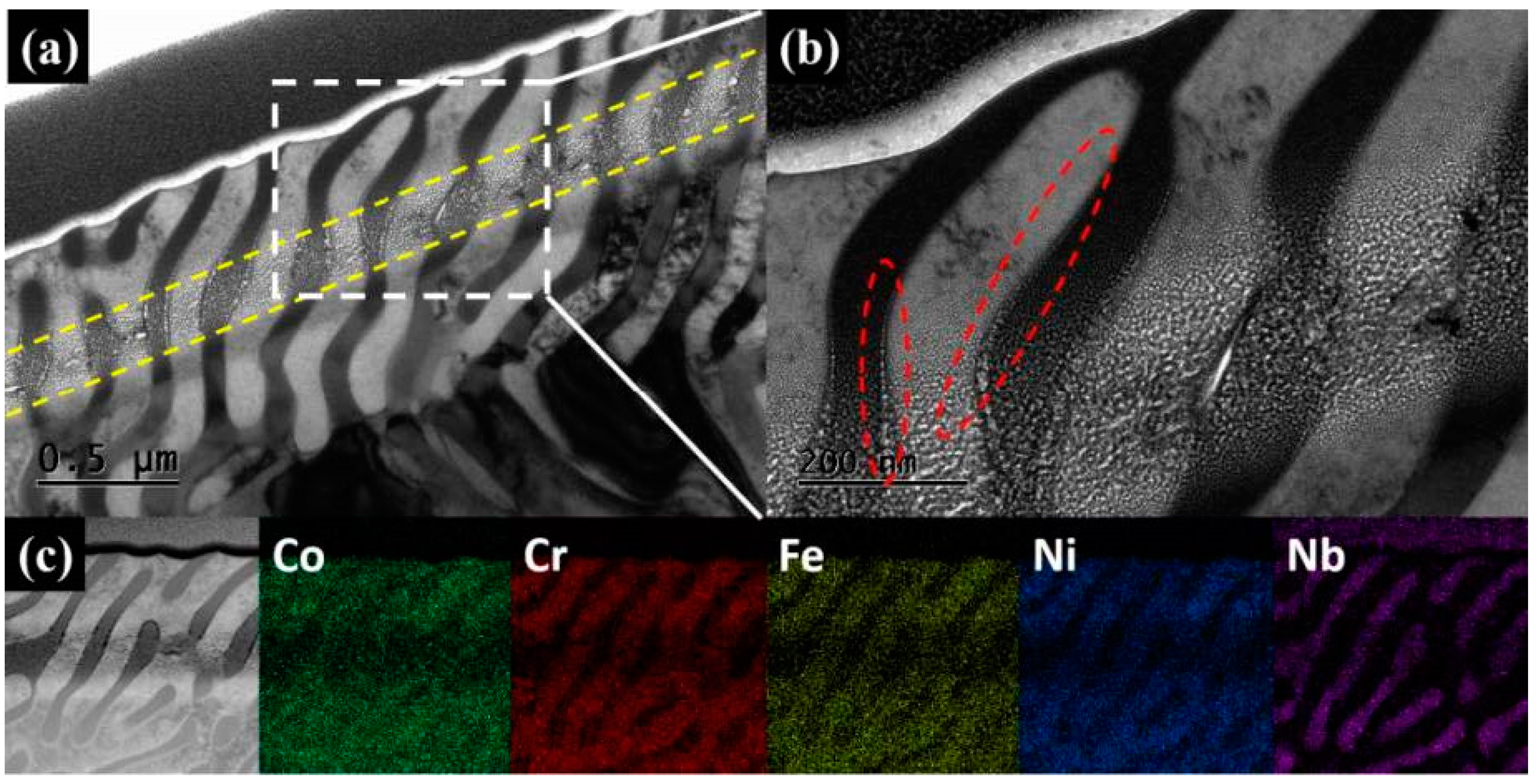
The microstructure of the irradiated EHEAs was further studied by TEM.
Figure 4a shows the TEM bright-field profiles of irradiated samples prepared by FIB at the fluence of 1.0×10
18 ions/cm
2.
Figure 4b shows the TEM bright-field images of the irradiated regions at high magnifications. And the corresponding elemental distribution of Co, Cr, Fe, Ni and Nb are shown in
Figure 4c. The light and dark stripes in the photo correspond to the matrix phase and the Nb-rich phase in the material, respectively. In particular, a clear layer of helium bubbles appears about 500 nm from the surface of the sample, as shown by the yellow line in
Figure 4a, and the size of the helium bubble increases from the sides of the helium bubble layer to the center. Surprisingly, along the boundaries of matrix and Nb-rich phase there is a neat line of helium bubbles that is longer than the width of the helium bubble. The closer the helium bubble is to the center, the larger the size of the helium bubble is. And the farther away the bubble is from the center, the smaller it gets, until it disappears. This kind of helium bubble aggregation behavior is common in the irradiation study of nanometer multilayer composites. Previous work has shown that helium bubbles and cavities preferentially form in the grain boundaries of ultrafine and nanocrystalline tungsten, as well as other composite structures[16-20]. Li et al.[
21] found that helium bubbles gathered along the Fe/W interface by irradiating Fe/W nanolayered composites with He ions. In fact, defects such as dislocations, voids and interfaces act as nucleation sites for irradiation-induced point defects in the early stages of helium bubble formation. Dislocations absorb more gaps than vacancies, and thus are preferred regions for helium bubble nucleation. Singh et al.[
22] suggested that the effect of grain size on radiation damage was mainly due to the depletion of vacancies within grains and their migration to grain boundaries. And vacancy clusters grow and capture He to form helium bubbles. Similar to grain boundaries, the phase boundary in this study also appears to be a favorable location for helium bubble nucleation. Therefore, helium bubbles accumulate along the phase boundary and form a small to large arrangement with the trend of He concentration.
3.3. Mechanical behavior
The average microhardness of CoCrFeNiNb
0.65 EHEAs surface was measured by nano-indentation method and and the radiation hardening behavior was studied.
Figure 5 shows typical depth profiles of nanoindentation hardness of pristine and irradiated CoCrFeNiNb
0.65 EHEAs at different irradiation fluence. The matrix phase and the Nb-rich phase of the sample were selected for hardness measurement respectively. As shown in
Figure 5, irradiation-induced hardening occurred in both matrix phase and the Nb-rich phase at the fluence of 5.0×10
17 ions/cm
2. With the ion fluence increasing to 1.0×10
18 ions/cm
2 and 2.0×10
18 ions/cm
2, as the radiation fluence continued to increase, the irradiation induced hardening behavior gradually weakened, and softening appeared.
4. Discussion
The schematic in
Figure 6 illustrates the radiation response of CoCrFeNiNb
0.65 EHEAs during He
+ irradiation. Normal dislocation slip occurred within the pristine sample when indented into the sample surface, as shown in
Figure 6a. According to
Figure 6b, at the fluence of 5.0×10
17 ions/cm
2, CoCrFeNiNb
0.65 EHEAs exhibit marked hardening behavior. Generally, in crystalline materials, irradiation-induced hardening is attributed to the interaction between irradiation-induced defects, and two types of approximate defect obstruction models have been used: the Orowan model[
23,
24] for strong barriers (i.e., interstitials, interstitial loops, and precipitates); Friedel-Kroupa-Hirsch (FKH) model[
21,
25] for weak barriers (i.e., helium bubbles). According to dislocation theory, the critical pressure for exiting a dislocation loop from the surface of a helium bubble can be expressed as,
Where,
γ is the surface free energy. Once the internal pressure of the helium bubble is greater than the critical pressure, it sprints out of the dislocation loops, which impede the movement of the dislocation:
Where,
is the coefficient of dislocation ring hardening.
and
are the density and size of the dislocation ring, respectively, depending on the size, internal pressure and density of the corresponding helium bubble. For the FKH model in crystalline materials, it can be written as,
Where,
M is the Taylor factor,
μ is the shear modulus, and
b is the Burgers vector. Therefore, the formation and evolution of helium bubbles at the initial stage of irradiation have made some contributions to irradiation-induced hardening. On the other hand, although some He atoms have been combined with vacancy to form He bubbles in CoCrFeNiNb
0.65 EHEAs, there are still a large number of isolated He atoms or He clusters in the system. Research[
26] shows that at low temperature, interstitial atoms near dislocations can easily migrate to the dislocation core, thus preventing dislocation from slipping. In addition, according to early studies of helium bubbles[27-29], the elastic interaction between two pressurized bubbles causes an attractive force between them. With the rapid growth of helium bubbles, the attraction between them increases, which increases the internal stress within the matrix and may lead to an increase in hardening in the He concentration region. Given the difficulty in estimating the small radiation hardening of helium bubbles and measuring the density of dislocation loops, the explanation of the radiation-induced hardening mechanism in CoCrFeNiNb
0.65 EHEA is complicated. However, radiation-induced hardening may result primarily from dislocation loops and interstitial atoms, as well as the interaction between helium bubbles and dislocations.
In this study, it is suggested that as the helium bubble grows and exceeds the critical size with the fluence increased up to 1.0×10
18 ions/cm
2 and 2.0×10
18 ions/cm
2, the region near the helium bubble does not provide enough space for its continuous growth, and the overlapping helium bubble may negatively affect the local hardening of CoCrFeNiNb
0.65 EHEA, as shown in
Figure 6c. Furthermore, the continuous coalescence and overlap of helium bubbles may cause large voids or open volume regions in the helium bubble layer, eventually leading to softening due to structural collapse. Meanwhile, this process is also accompanied by swelling and peeling of the sample surface, which is consistent with the microscopic morphology in
Figure 3.
5. Conclusions
CoCrFeNiNb0.65 EHEAs prepared by arc melting were irradiated with a 100 keV He+ ion beam at fluences of 5.0×10¹⁷ ions/cm2, 5.0×10¹⁷ ions/cm2, and 1.0×10¹⁸ ions/cm2 at room temperature. XRD results proved that CoCrFeNiNb0.65 EHEAs are composed of FCC and laves phases. And no obvious phase decomposition occurred under any irradiation condition, which is consistent with high configurational entropy playing a significant role in phase stability. The SEM results indicated the surface morphology of the samples was mainly composed of two phases, matrix phase and petal-like Nb-rich phase. When the ion fluence increased to 1.0×10¹⁸ ions/cm2, the irradiation-induced swelling occurred on the sample surface, and as the fluence increasing to 2.0×10¹⁸ ions/cm2, the swelling became increasingly severe and the surface of Nb-rich phase appeared peeling and shedding, which suggested that the degree of swelling varied between the two phases under the same irradiation condition. TEM results showed an interesting result that along the boundaries of matrix and Nb-rich phase there was a neat line of helium bubbles that was longer than the width of the helium bubble. The closer the helium bubble is to the center, the larger the size of the helium bubble was. And the farther away the bubble was from the center, the smaller it gets, until it disappeared,which was common in the irradiation study of nanometer multilayer composites. Nanoindentaion was performed to indicate that hardening and softening induced by He+ ion irradiation occurred in various ion fluences. At ion fluence of 5.0×10¹⁷ ions/cm2, the CoCrFeNiNb0.65 EHEAs exhibited an obvious hardening behavior, which can be explained by dislocation-dominated hardening effect. When the ion dose reached 1.0×10¹⁸ ions/cm2 and 2.0×10¹⁸ ions/cm2, the hardening effect decreased probably due to the helium bubble aggregation and growth, as well as helium bubbles induced noncompact structures.
Author Contributions
Conceptualization, Y.L. and Y.W.; software, H.Z.; validation, Y.L. and Y.W.; formal Analysis, Y.W.; investigation, Y.W. and Y.L.; resources, A.W.; data curation, Y.W. and H.Z.; writing-original draft preparation, Y.W.; writing-review & editing, Y.W. and Y.L.; visualization, Y.W.; supervision, A.W. and Y.L.; project administration, H.Z. and Y.L.
Funding
This work was supported by the National Natural Science Foundation of China (Grant No. 51401028, No. 51271193, No. 11402277, No. 11790292) and the Strategic Priority Research Program of the Chinese Academy of Sciences (Grant No. XDB22040303). This work was also supported by the Innovation Program (237099000000170004).
Conflicts of Interest
The authors declare no conflict of interest.
References
- Yeh, J.W.; Chen, S.K.; Lin, S.J.; Gan, J.Y.; Chin, T.S.; Shun, T.T.; Tsau, C.H.; Chang, S.Y. Nanostructured High-Entropy Alloys with Multiple Principal Elements: Novel Alloy Design Concepts and Outcomes. Advanced Engineering Materials 2004, 6, 299-303. [CrossRef]
- Cantor, B; Chang, I.T.H.; Knight, P.; Vincent, A.J.B. Microstructural development in equiatomic multicomponent alloys. Materials Science and Engineering: A 2007, 375-377, 213-218. [CrossRef]
- Zhang, Y.; Zuo, T. T.; Tang, Z.; Gao, M.C.; Dahmen, K.A.; Liaw, P.K.; Lu, Z.P. Microstructures and properties of high-entropy alloys. Progress in materials science 2014, 61, 1-93. [CrossRef]
- Wang, Y.; Zhang, K.; Feng, Y.H.; Li, Y.S.; Tang, W.Q.; Zhang, Y.T.; Wei, B.C.; Hu, Z. A. Excellent irradiation tolerance and mechanical behaviors in high-entropy metallic glasses. Journal of Nuclear Materials 2019, 527, 151785. [CrossRef]
- Wang, Y.; Zhang, K.; Feng, Y.H.; Li, Y.S.; Tang, W.Q.; Zhang, Y.T.; Wei, B.C.; Hu, Z. Mechanism of local hardening in metallic glass during He ion irradiation. Materialia 2020, 11, 100691. [CrossRef]
- Zhang, Y.; Zhou, Y.J.; Lin, J.P.; Chen, G.L.; Liaw, P.K. Solid-solution phase formation rules for multi-component alloys. Advanced engineering materials 2008, 10, 534-538. [CrossRef]
- Lu, C.Y.; Niu, L.L.; Chen, N.J.; Jin, K.; Yang, T.N.; Xiu, P.Y.; Zhang, Y.W.; Gao, F.; Bei H.B.; Shi, S.; He, M.R.; Robertson, I.M.; William, J.W.; Wang, L.M. Enhancing radiation tolerance by controlling defect mobility and migration pathways in multicomponent single-phase alloys. Nature Communications 2016, 7, 13564. [CrossRef]
- Li, N.; Huang, S.; Zhang, G.D.; Qin, R.Y.; Liu, W.; Xiong, H.P.; Shi, G.Q.; Blackburn, J. Progress in additive manufacturing on new materials: a review. Journal of Materials Science & Technology 2015, 35, 242-269. [CrossRef]
- Zhang, Y.; Yang, T.F.; Xia, S.Q.; Liu, S.X. Irradiation Resistance in AlxCoCrFeNi High Entropy Alloys. JOM 2015, 67, 2340-2344. [CrossRef]
- Lu, Y.P.; Dong, Y.; Jiang, H.; Wang, Z.J.; Cao, Z.Q.; Guo, S.; Wang, T.M.; Li, T.J.; Liaw, P.K. Promising properties and future trend of eutectic high entropy alloys. Scripta Materialia 2020, 187, 202-209. [CrossRef]
- Lu, Y.P.; Dong, Y.; Guo, S.; Jiang, L.; Kang, H.J.; Wang, T.M.; Wen, B.; Wang, Z.J.; Jie, J.C.; Cao, Z.Q.; Ruan, H.H.; Li, T.J. A Promising New Class of High-Temperature Alloys: Eutectic High-Entropy Alloys. Scientific Reports 2014, 4, 6200. [CrossRef]
- Pang, J.Y.; Xiong, T.; Yang, W.F.; Ge, H.L.; Zheng, X.D.; Song, M.; Zhang, H.W.; Zheng, S.J. Atomic scale structure dominated FCC and B2 responses to He ion irradiation in eutectic high-entropy alloy AlCoCrFeNi2.1. Journal of Materials Science & Technology 2022, 129, 87-95. [CrossRef]
- He, F.; Wang, Z.J.; Shang, X.L.; Leng, C.; Li, J.J.; Wang, J.C. Stability of lamellar structures in CoCrFeNiNbx eutectic high entropy alloys at elevated temperatures. Materials & Design 2016, 104, 259-264. [CrossRef]
- Maity, T.; Prashanth, K.G.; Balçi, Ö.; Wang, Z.; Jia, Y.D.; Eckert, J.H. Plastic deformation mechanisms in severely strained eutectic high entropy composites explained via strain rate sensitivity and activation volume. Composites Part B: Engineering 2018, 150, 7-13. [CrossRef]
- Egeland, G.W.; Valdez, J.A.; Maloy, S.A.; McClellan, K.J.; Sickafus, K.E.; Bond, G.M. Heavy-ion irradiation defect accumulation in ZrN characterized by TEM, GIXRD, nanoindentation, and helium desorption. Journal of Nuclear Materials 2013, 435, 77–87. [CrossRef]
- Shi, Y.Z.; Jiang, Z.Y.; Xia, T.J.; Zhang, W.J.; Yang, P.S.; Ren, X.Y.; Wang, M.Q.; Liang, L.S.; Cao, X.Z.; Zhu, K.G. Helium diffusion and bubble evolution in single-phase tungsten-based W-Ta-Cr-V complex concentrated alloy. Journal of Nuclear Materials 2023, 578, 154335. [CrossRef]
- Jiang, W.L.; Kovarik, L.; Kruska, K.; Fu, Y.C.; Hu, Z.H.; Shao, L.; Setyawan, W. Behavior and properties of helium cavities in ductile-phase-toughened tungsten irradiated with He+ ions at an elevated temperature. Materialia 2023, 29, 101789. [CrossRef]
- Pu, G.; Sun, H.X.; Wang, Y.H.; Li, J.; Du, X.J.; Liu, B.; Ren, D.; Zhang, K.; Li, G.Z.; Lin, L.W. Effect of periodic thickness on the helium bubble evolution and irradiation hardening in Cu/W(Re) multi-layered films under helium ion irradiation. Journal of Alloys and Compounds 2023, 935, 167978. [CrossRef]
- Lv, S.S.; Shen, Y.H.; Zhu, R.; Zhou, Q.; Shi, L.; Sun, L.B.; Li, Z.C. The irradiation effects on the nanoindentation hardness and helium bubbles evolution mechanism of Ni-based alloy. Radiation Physics and Chemistry 2023,206, 110763. [CrossRef]
- Jiang, M.H.; Mir, A.H.; Bahri, M.; Zhang, Y.J.; Browning, N.; Whittle, K.; Patel M. Helium bubbles in Gd2Ti2O7 borosilicate glass-ceramic composites. Journal of Nuclear Materials 2023,581, 154424. [CrossRef]
- Li, N,; Fu, E.G.; Wang, H.; Carter, J.J.; Shao,L.; Maloy, S.A.; Misra, A.; Zhang, X. He ion irradiation damage in Fe/W nanolayer films. Journal of Nuclear Materials 2009, 389, 233-238. [CrossRef]
- Singh, B. N. Effect of grain size on void formation during high-energy electron irradiation of austenitic stainless steel. Philosophical Magazine 1974, 29, 25-42. [CrossRef]
- Yu, L.; Xiao, X.Z.; Chen, L.R.; Chu, H.J.; Duan, H.L. A micromechanical model for nano-metallic-multilayers with helium irradiation. International Journal of Solids and Structures 2016, 102-103, 267-274. [CrossRef]
- Dérès, J.; Proville, L.; Marinica, M.C. Dislocation depinning from nano-sized irradiation defects in a bcc iron model. Acta Materialia 2015, 99, 99-105. [CrossRef]
- Zinkle, S.J.; Matsukawa, Y. Observation and analysis of defect cluster production and interactions with dislocations. Journal of Nuclear Materials 2004, 329-333, 88-96. [CrossRef]
- Orowan, E. Symposium on Internal Stresses in Metals and Alloys; Institute of Metals: London, UK, 1948.
- Seeger, A.K. On the theory of radiation damage and radiation hardening. In Proceedings of the Second United Nations International Conference on the Peaceful Uses of Atomic Energy, Geneva, Switzerland, 1–13 September 1958, 250–273.
- Grossbeck, M.L.; Maziasz, P.J.; Rowcliffe, A.F. Modeling of strengthening mechanisms in irradiated fusion reactor first wall alloys. Journal of Nuclear Materials 1992, 191-194, 808-812. [CrossRef]
- Garner, F.A.; Hamilton, M.L.; Panayotou, N.F.; Johnson, G.D. The microstructural origins of yield strength changes in aisi 316 during fission or fusion irradiation. Journal of Nuclear Materials 1981, 104, 803-807. [CrossRef]
|
Disclaimer/Publisher’s Note: The statements, opinions and data contained in all publications are solely those of the individual author(s) and contributor(s) and not of MDPI and/or the editor(s). MDPI and/or the editor(s) disclaim responsibility for any injury to people or property resulting from any ideas, methods, instructions or products referred to in the content. |
© 2023 by the authors. Licensee MDPI, Basel, Switzerland. This article is an open access article distributed under the terms and conditions of the Creative Commons Attribution (CC BY) license (http://creativecommons.org/licenses/by/4.0/).


