1. Introduction
Ultra-low-loss (ULL) optical fiber, with lower transmission loss, more stable transmission performance and excellent long-link transmission capability, is often used in areas with harsh transmission environments, such as sparsely populated areas, uninhabited areas, and especially at high altitudes. Our research team has studied the fiber loss [
1,
2,
3,
4] and fiber strength [
5] under the special environment of high altitude, and found that the change of altitude can have a great impact on the optical fiber splicing point, and also studied the safety of the entire fiber link communication system [
6]. However, the stable and reliable operation of the entire optical fiber communication link in high altitude areas needs to be further studied, because the environment is extremely harsh at high altitude and the cost of maintenance is extremely huge. Once the optical fiber link system is built, it is not desirable to conduct frequent maintenance. It is worth noting that due to defects and external factors in the manufacturing process of the fiber optic structure itself, the fiber optic line is accidentally damaged, which in turn causes the paralysis of the fiber optic line; by using the failure of the fiber optic line, the interception of fiber optic signals has become increasingly easy and covert, at which point, fiber optic communication is no longer safe and reliable [
7]. Therefore, it becomes very important to find and recover faults of optical fiber lines early in order to ensure the smooth flow of optical communication network system. Currently, Optical Time Domain Reflectometer (OTDR) is the main measurement instrument used in optical cable line inspection [
8,
9,
10,
11]. Especially in fiber-optic monitoring systems, OTDR is often used to determine the location of fiber-optic fault points or the fiber length of splice loss [
12,
13,
14,
15,
16,
17]. J.Z.Christopher has proposed an algorithm to detect and locate fiber faults by digital signal processing of OTDR data by using the method of Gabor series and Rissanen’s minimum description length criterion [
8,
9,
10], however, the noise in the actual measurement is not very ideal. M.S.Ab-Rahman has proposed and demonstrated a MATLAB-based graphical user interface (GUI) that is capable of measuring optical signal levels, attenuation and locating breakpoints in faulty optical fibers [
12], but the theoretical study of this literature lacks in-depth analysis. J.P.V.D.Weid distinguishes meaningful level shifts from typical signal fluctuations, which in turn is associated with the problem of identifying small losses in noisy OTDR profiles [
13], but this method can not average out the noise by increasing the acquisition period. K.Abdelli detects, locates, and estimates the fault of optical fiber by extracting signals from monitoring data obtained by OTDR, which is commonly used for fault diagnosis of fiber link [
16,
17], but this method is mainly used in the case of high signal-to-noise ratios and takes longer time under the case of low signal-to-noise ratios. In particular, these literatures all do not consider the application scenarios of non-relay, large span ultra-long optical fiber links, especially at high altitudes.
This paper discusses the principles and key techniques of OTDR curve and fault location, and analyzes OTDR signals theoretically by using wavelet transform, and finally realizes noise reduction and singularity location of OTDR data generated on actual fiber optic lines through simulation. The real-time detection of long-span, relay-free and ultra-long fiber link communication at high altitudes is carried out and a large number of field test data are collected. The theoretical analysis is basically consistent with the experimental data. The accuracy of fiber fault location is greatly improved. The method has been directly applied to the on-site detection of relay-free, large-span and ultra-long fiber links at high altitudes, which has certain significance for ensuring the reliable operation and real-time monitoring of fiber communication links in the future.
2. Materials and Methods
OTDR curve analysis is a very important part of fiber remote fault diagnosis. In 1976, Barnoski has explained the potential application of optical backscattering in optical measurement [
18] and then OTDR is developed on this basis. OTDR is a precision optoelectronic integrated instrument made by using the Rayleigh scattering and backscattering generated by Fresnel reflection of optical signals during transmission in optical fibers. This instrument is mainly used for fault monitoring of fiber optic communication links and is an indispensable instrument for fiber communication technology [
19].
Under ideal conditions, OTDR can accurately measure the characteristics of fiber. However, due to equipment accuracy and other reasons, the OTDR curve signal contains a large noise component, especially at the tail end of the curve. Interestingly, its working principle is similar to that of a radar. A pulse light signal is injected into the measured fiber and when these signals encounter the fusion points, connectors, bends, fractures or the ends of fiber, some of them are scattered and reflected back into the OTDR [
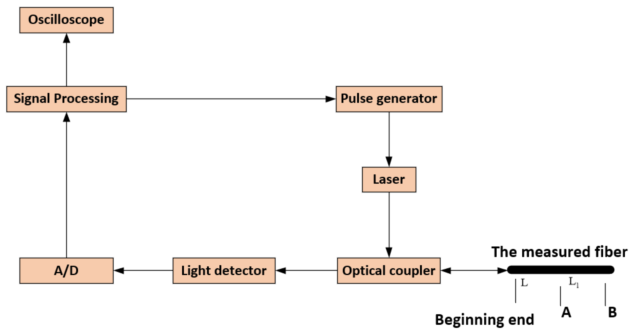
20]. The useful information returned is measured by the optical detector of OTDR and is used as segments at different locations within the fiber. The fiber characteristics are determined by analyzing these reflected back optical signals. The OTDR consists of light source, directional coupler, light detector, sampling analyzer and oscilloscope [
21], as shown in
Figure 1.
OTDR uses Rayleigh scattering and Fresnel reflection to characterize optical properties [
21,
22]. When light is transmitted in an optical fiber, Rayleigh scattering is caused by the slight fluctuation of the refractive index of fiber, while Fresnel reflection is caused by the abrupt change of the refractive index at the end face or fault point of fiber, which is a discrete reflection. Notably, Rayleigh scattering is determined by the properties of the fiber material itself, while Fresnel reflection is related to the actual operation and state of each fiber and reflects the "point" event on the fiber.
The Rayleigh scattering signal generated by OTDR is a slow downward decaying curve that decreases as the laser beam travels a greater distance through fiber. According to scattering principle, the optical power of Rayleigh backscattering is proportional to the pulse width of the incident laser beam when the signal wavelength is determined. Especially, the longer pulse width is, the stronger Rayleigh backscattering becomes. The power reflected from the fiber, namely, the Rayleigh backscattered light power obtained by the OTDR optical receiver,
, can be calculated by Equation (
1).
Where
L=
represents distance from the fiber injection end;
c represents speed of light in vacuum;
represents propagation speed of light in fiber;
represents the pulse power at the injection end of the optical fiber at t = 0, namely, the peak power of the optical pulse injected into optical fiber;
=
represents incident laser pulse width;
represents pulse space;
=
represents Rayleigh scattering attenuation coefficient;
represents total Rayleigh scattering power;
represents attenuation coefficient of fiber;
S represents the ratio of back Rayleigh scattering power to total Rayleigh scattering power, also called back scattering coefficient, and for single-mode fiber,
Where
=
represents the numerical aperture of optical fiber;
and
are the refractive index of the core and cladding, respectively;
r represents fiber core radius;
represents spot size. In addition, the normalized frequency
V is a fiber structure parameter proportional to the optical wave frequency and can be expressed as Equation (
3).
Where = represents phase constant; is the operating wavelength.
Fresnel reflection is caused by individual points in the whole fiber. It is worth noting that these points can occur at any joint point in the fiber, where there is serious geometric distortion or where the fiber is broken or disconnected. At this time, the change of backscattering coefficient due to the change of refractive index can generate strong backscattered light. OTDR captures these optical signals and uses them to determine the fault point, breakpoint and other information of the optical fiber. Especially, the width of the laser pulse injected into the fiber from OTDR is adjustable and the period of the OTDR emission pulse can be calculated [
21], as shown in Equation (
4).
Where t represents total time from the signal transmitter to the receiver; n represents the specified refractive index.
Let the power reflection coefficient of the optical fiber be
. Then, the power returned from the optical fiber, namely, the Fresnel reflected light power obtained by OTDR optical receiver,
, can be calculated by Equation (
5).
From Equation (
1) and Equation (
5), both Rayleigh scattered power and Fresnel reflected power are proportional to their backscattering coefficients and inversely proportional to their attenuation coefficients. Moreover, the smaller the backscattering coefficient is, the smaller the reflected power becomes, and conversely, the larger the reflected power becomes. In addition, it can be seen from Equation (
2) that the backscattering coefficient of a single-mode optical fiber is in turn inversely proportional to the core diameter, spot size, and operating wavelength of the optical fiber.
Singularities, irregular and abrupt parts of the signal often carry more important information. The Fourier transform has been one of the most widely used tools in the field of signal processing. Unfortunately, the analysis of non-smooth signals based on the Fourier transform can not provide complete information. Wavelet transform (WT) inherits and develops the idea of Fourier transform localization, overcoming the disadvantages of the window size not being able to vary with the frequency. It has good localization characteristics and the advantages of both time and frequency domain analysis and thus can focus on any details of the signal object.
Let
be a square integrable function, namely
, if its Fourier transform
satisfies:
Then,
is said to be a permissible wavelet and Equation (
6) is said to be the permissible condition of the wavelet function. Analyzing the inner product of the wavelet function and the signal
, the time domain expression of the wavelet transform can be obtained, as expressed in Equation (
7).
Meanwhile, the frequency domain of wavelet transform equivalent can be expressed by Equation (
8).
Where represents the signal to be analyzed; and are the Fourier transforms of and , respectively. By properly selecting the basis wavelet, it is possible to have limited support for in the time domain and it is also more concentrated in the frequency domain. In other words, WT can show the local features of the signal in both time domain and frequency domain, which is very beneficial to detect transient signals or singularities.
Mutation signals are divided into edge-hopping and peak-hopping. In signal analysis, mutant signals have singularity at mutation point. The signal singularity can be detected from the modal maxima of its wavelet transform [
23]. In a few words, under the scale
, in a certain neighborhood
of
, for any
t, it satisfies:
The point is the modal extremum of the wavelet transform. Especially, it is still the modal extremum of the wavelet transform at .
In fiber optic fault diagnosis system, we mainly focus on the location and the type of the fault so that we can restore the optical communication operation in time. A strong light narrow pulse is injected into the input end of the measured optical fiber. Due to the actual nonuniformity inside the optical fiber, the light can be scattered along each point of the optical fiber when it is transmitted inside the optical fiber and then the scattered light can return to the incident end of the optical fiber in the direction opposite to the incident light in the optical fiber. Because the main scattering mechanism is Rayleigh scattering, the detection of the backscattered light power at each point along the length of the optical fiber all contains the information of the loss of light in the optical fiber transmission. Therefore, the loss characteristics and defect points of the optical fiber can be analyzed and judged.
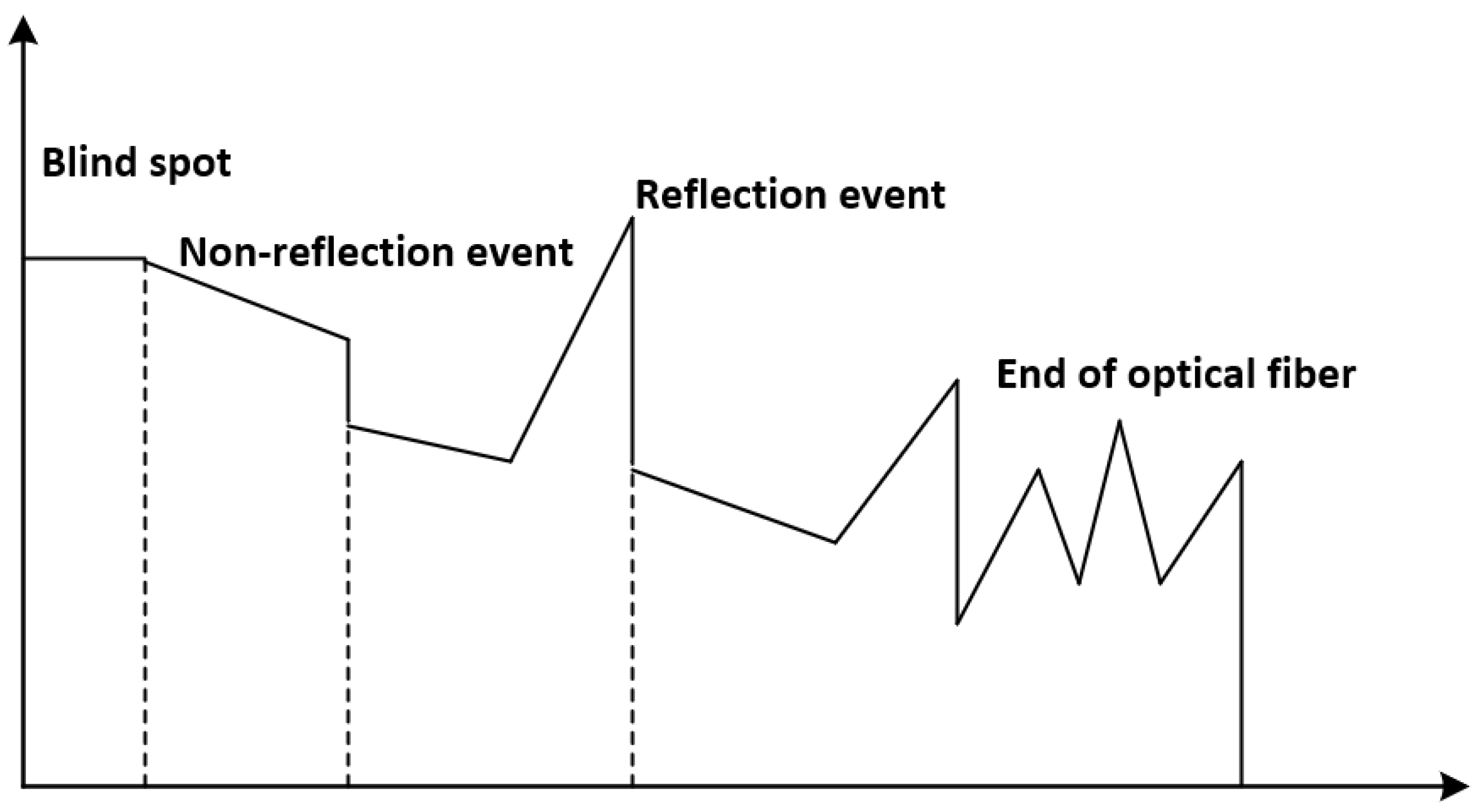
Generally speaking, the events on the OTDR test curve can be divided into blind spots, non reflection events, reflection events and optical fiber terminals, as shown in
Figure 2.
In order to accurately detect events, the noise is sufficiently suppressed while highlighting useful information. We do first perform wavelet transform on the OTDR curve data, and then perform threshold filtering on the high-frequency information, and finally perform energy operation, since the mutation information exists in the high-frequency information after wavelet decomposition, as shown in
Figure 3. Furthermore, the event information is retained in the curve and enhanced, while the noise in the curve is sufficiently suppressed, which is very beneficial for the detection of the event points. Fortunately, the location of an event point is accurately examined by the event detection algorithm [
24].
Due to equipment accuracy and other reasons, the OTDR curve signal contains a large noise component, especially at the tail part of the curve. Therefore, it is very necessary to do noise reduction on the curve before curve analysis as well as fault location and diagnosis. Further, the curve data is displayed digitally and analyzed based on the assumptions of the parameters of the tracking analysis of the curve. Then, certain event points are identified on the curve. Consequently, the operating status of the fiber is obtained.
The actual signal measurement process generally introduces noise. The OTDR detected data is a linear combination of the original data and noise. Coincidentally, WT is a linear transform, so the WT value of detected data is also superimposed from that of original data and that of noise. Therefore, WT mode maxima can be generated by the test noise. For the actual signal, the WT mode maxima can test its singularity to determine the occurrence time and recovery time of the event when the background noise signal is strong. However, there can be a large error at this time. In order to reduce the impact of the error, the signal can be denoised, both to eliminate the noise after the display of high-frequency quantities, and also to retain some of these high-frequency quantities in response to sudden changes in signal.
According to the attenuation characteristics of optical fiber communication, the OTDR signal containing noise can be expressed as Equation (
10).
Where represents the true signal; represents the noise signal; represents the signal containing noise. Special attention can be paid to the preservation of useful signals and recovery of the true signal from when noise reduction is applied to the signal, since the OTDR curve event points are high-frequency signals.
Here, the signal-to-noise ratio (SNR) is used to measure the effect of OTDR curve signal noise reduction, which can be calculated by Equation (
11).
Where
represents the real signal power;
represents the noise power. They can be shown by Equation (
12) and Equation (
13), respectively.
and
Where represents the original signal; represents the signal after wavelet noise reduction.
Except for the low-frequency component, the wavelet coefficients of each component are distributed almost symmetrically on both sides of zero point [
25]. Most of small-scale coefficients are small. To keep the major edges, an intuitive and effective way to remove noise is to take a threshold value directly on the wavelet coefficients. And only by keeping the larger coefficients can the original signal be reconstructed, since the distribution of the wavelet coefficients is Gaussian normal. Based on WT, a threshold is given as noise standard deviation and N is given as the number of signal sampling points [
26]. Unfortunately, this threshold is too large when it is large and too small when it is small. So instead of using the factor
, it is usually generated by the constant
c, namely
T=
, which in turn achieves a "soft threshold" that calculates the absolute value of the wavelet coefficients, as shown by Equation (
14).
The threshold value given here is calculated as =, and in which type, m is the scale; is the scale with noise variance of m. Generally speaking, the best value c can vary with the different signals and the noise intensity. Experiments show that it is more appropriate to take c between 3 and 4 for ordinary signals, and here c=3.4641.
Considering that the curve can be influenced by other factors, we choose the orthogonal wavelet basis with low vanishing moment and small support length to realize the analysis of OTDR curve. Furthermore, we here let the wavelet scale be between 2 and 4 after many trials, since the signal used is the data obtained by noise reduction and specially the fiber length of fiber optic cables in high altitude areas is long.
4. Results and discussion
"Slope" is common in OTDR signal, which indicates clearly that there is loss at this place. There are many reasons for this phenomenon, such as joint defects. As described in the second part of the article, there are two different backscatter signal waveforms when OTDR is used to detect optical fiber link faults.
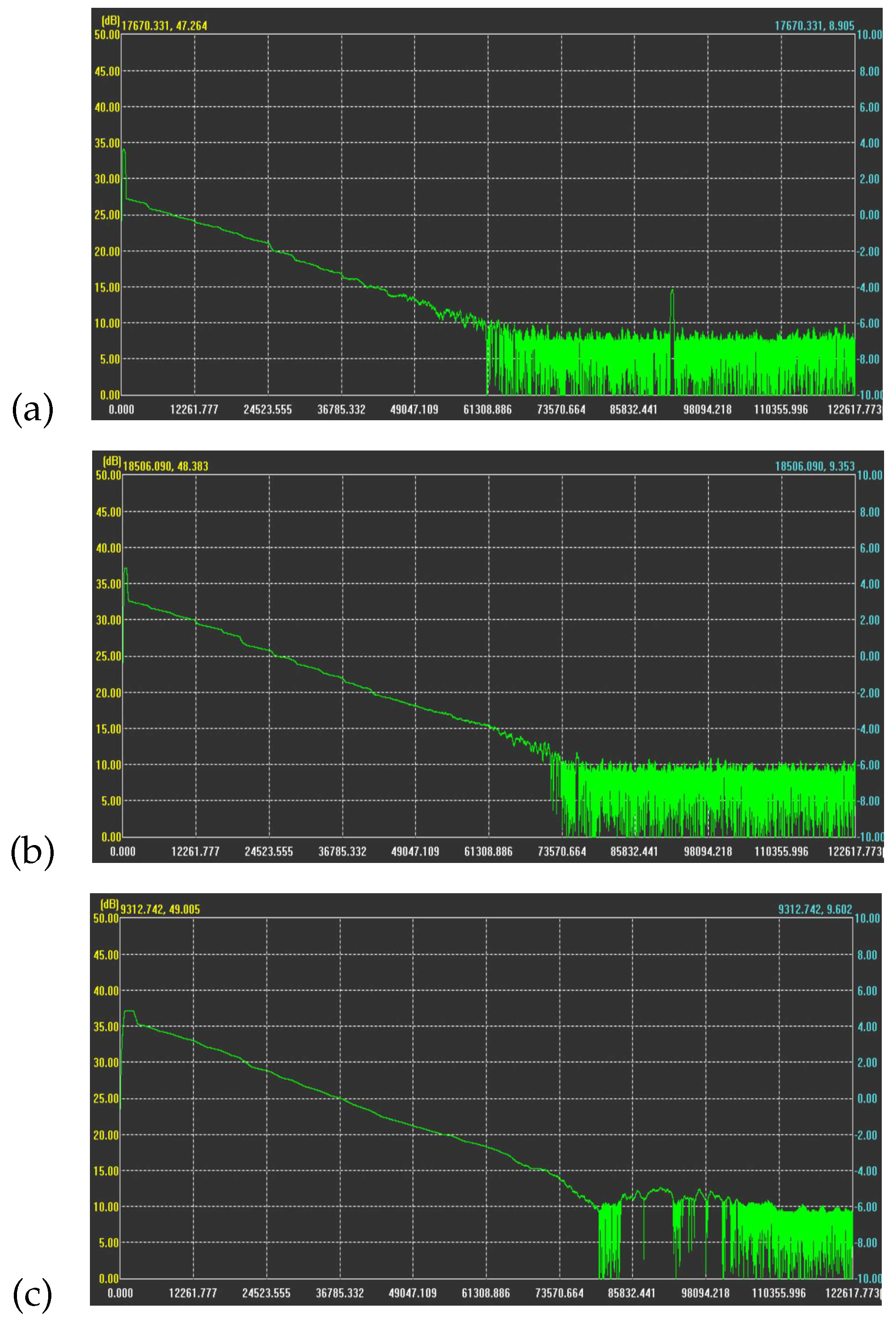
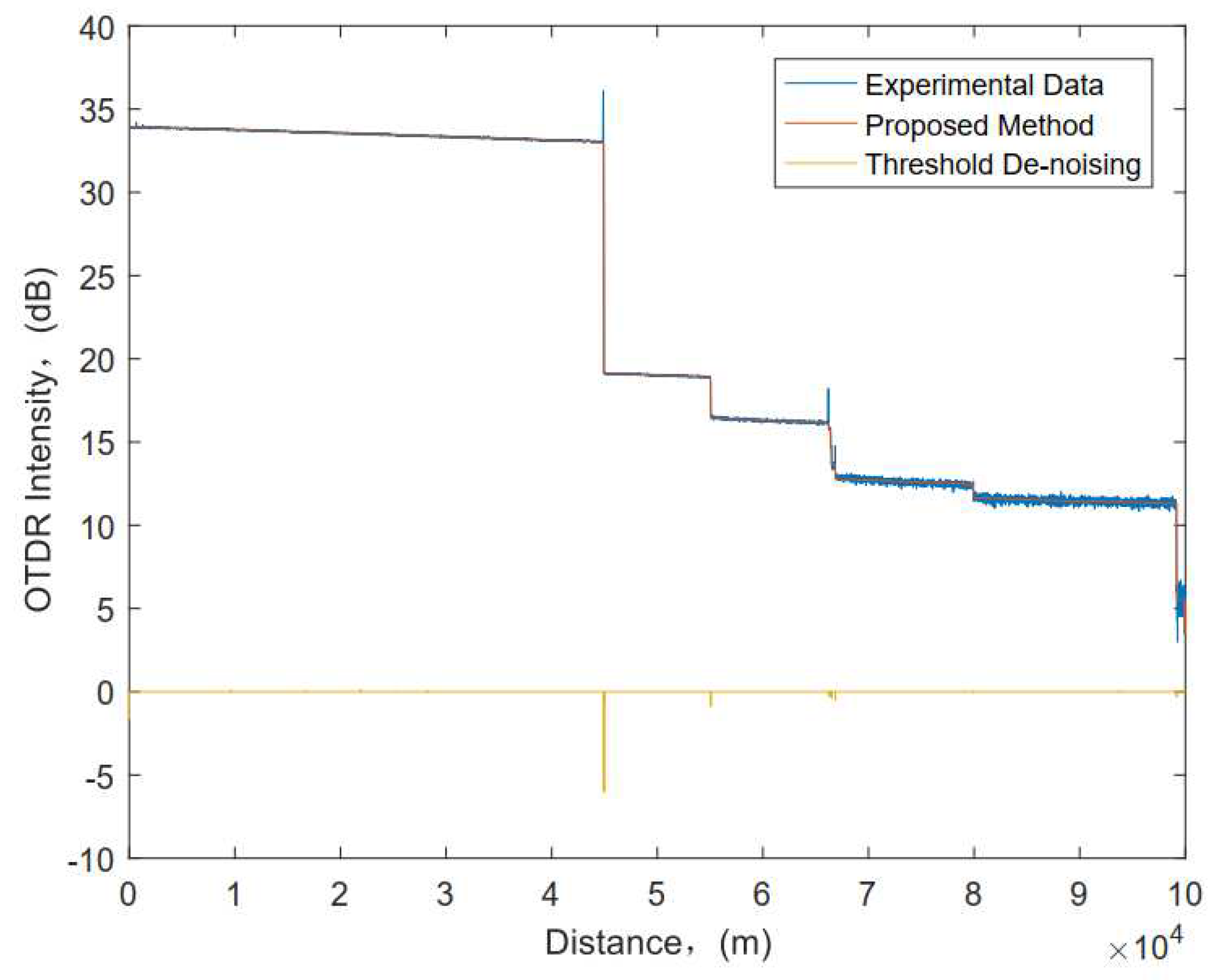
Figure 5 shows the real OTDR field test curve. Among them, the waveform shown in
Figure 5a has a strong Fresnel reflection peak and a very large negative step, which indicates that the optical fiber has a good termination at this fiber failure. Especially, the waveform shown in
Figure 5c has only one negative step, which indicates that the fiber link of the cable is crushed or broken at that location. By contrast, the fiber optic communication link shown in
Figure 5b is in good condition. In addition,
Figure 5a also shows that the signal after the negative step continues to be transmitted at low power. Namely, the OTDR receiving end still receives optical signal at this time, but it is lower than normal value, which implies the fault point is at the negative step.
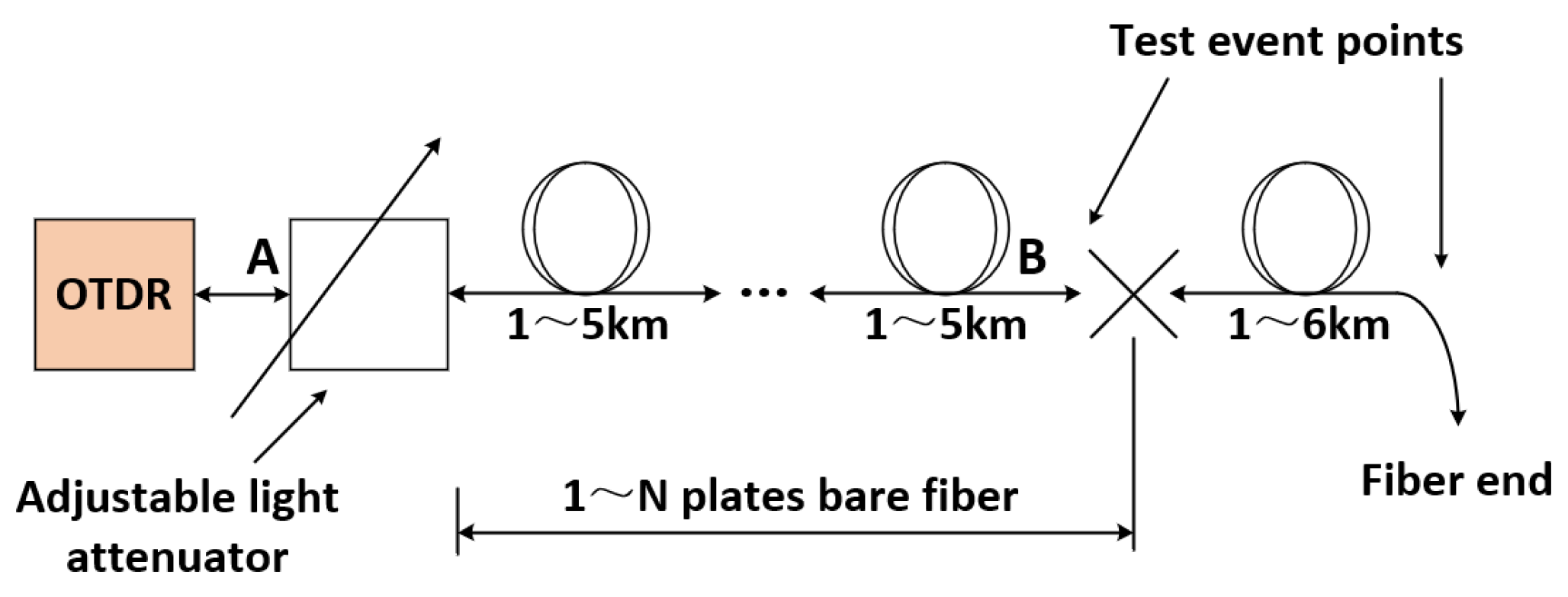
Figure 5c also shows that the fiber link from point
A to point
B in
Figure 1 and
Figure 4 is a fault section. There are many reasons for bringing errors to the accuracy of OTDR measurement. We assume that the OTDR equipment parameters have been well adjusted when analyzing the OTDR curve signal, which helps to evaluate the safe operation of optical fiber link communication.
According to the second part of this paper, OTDR collects and quantifies the returned backscatter signal on the basis of the return time, area difference and optical power variation in a sample, and then displays the measured fiber backscatter curve in the geometric plane on the Oscilloscope. The main role of OTDR is to measure the performance of fiber and to determine the location of failure point of fiber. As shown in
Figure 5, certain irregular singularities and abrupt changes in the OTDR curve signal contain some important information. We analyze the OTDR curve using WT according to its advantages in singular signal detection and signal filtering and combine with Equation (
14) to achieve accurate detection and localization of fault events under strong noise. Simulation results are shown in
Figure 6. When the signal encounters a fault or fiber break, a sharp reflected signal is superimposed on backward scattering signal, and the backward scattering curve reacting to original data has a large abrupt change at this time. The actual operation effect shows that using WT, the accuracy and precision of fiber fault location have been improved in performance, and the effect is remarkable.
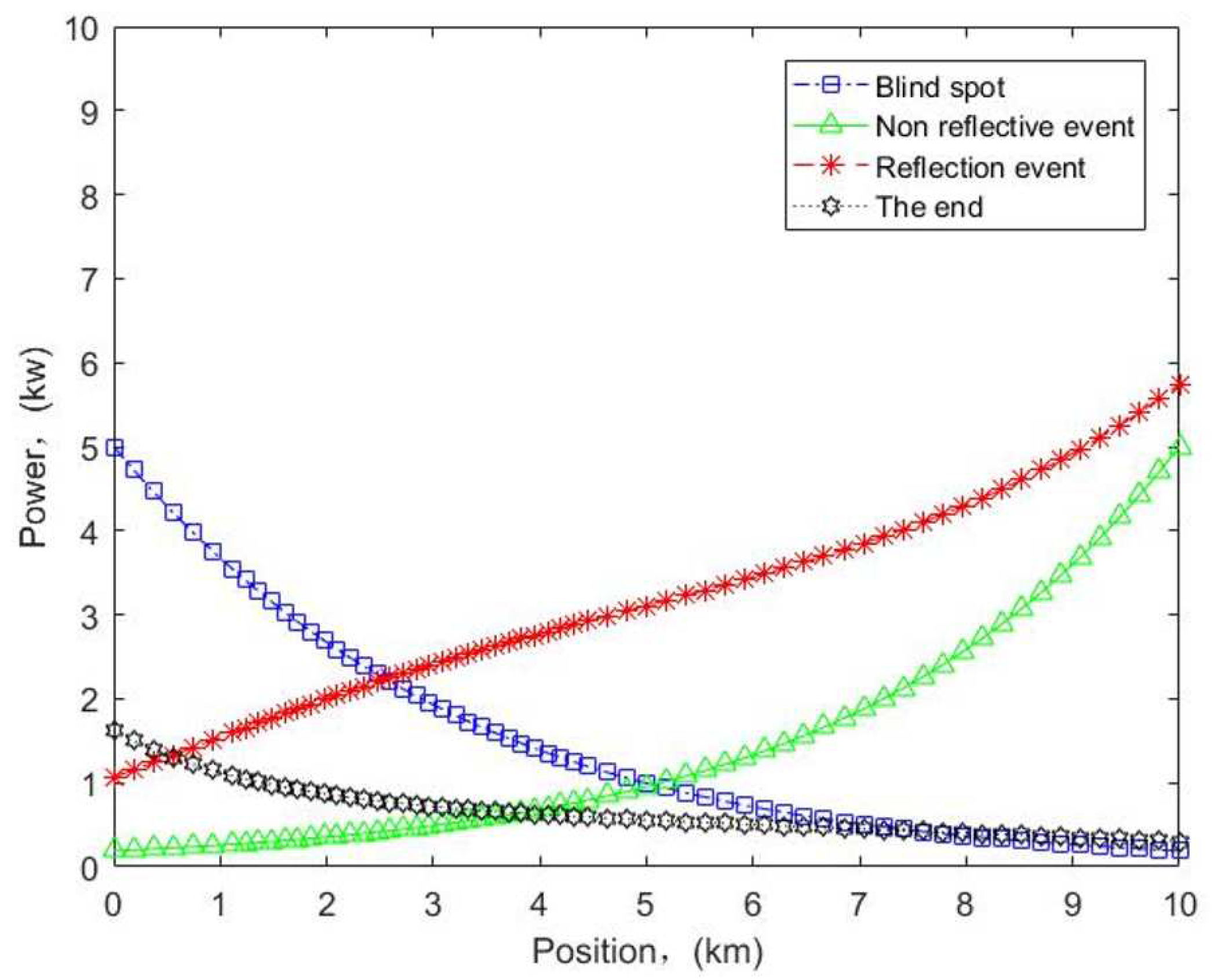
There are numerous reasons for fiber link failure, including fiber deformation due to external forces on the fiber, inadequate performance of the fiber itself, connector failure and external causes. To facilitate the analysis, we describe the fiber profile status of OTDR testing as event types containing blind spot, non-reflective event, reflective event and the end. According to the second part of this paper, the magnitude of the optical signal power can characterize advantages and disadvantages of transmission characteristics of the fiber optic cable line. The obtained amplitude of the optical power transformation is different for different fault conditions. Depending on the severity of the fault, the power can range from normal values to zero. Combining with Eq.(1), Eq.(4) and Eq.(5), we obtain the change trend of the power of different events transmitted along the fiber link, as shown in
Figure 7. The power gradually decreases with the increase of the transmission distance of signal. However, when the optical signal propagation occurs in a special state, reflection and other situations can occur, and the power can also change accordingly at this time. That the obtained power is smaller than the normal value indicates that the attenuation of the optical fiber link is increasing. And that the optical power at the receiving end is zero indicates that the transmission distance of the optical signal has reached its limit or that a complete interruption of the fiber has occurred, namely the highest level of failure. Specially, we can also record the time taken for optical signal to return from the transmission signal, and then determine propagation speed of optical signal in the fiber medium, and thus calculate the distance.
In the actual engineering, the useful curve signal is usually shown as some low frequency signal, elatively smooth signal or singularity signal, while the noise signal is usually the high frequency signal. It is worth noting that, OTDR curve event points are typically high-frequency signals, so special attention can be paid to the retention of the useful signal during the signal noise reduction, which is very beneficial to the subsequent recovery of the real optical signal from it. In conjunction with
Figure 5 and
Figure 6, we can decompose the original noisy signal under scale 3 to obtain the noise reduction threshold and then use the soft threshold method to process and reconstruct the OTDR curve signal, as shown in
Figure 8. Obviously, although the OTDR signal is disturbed by strong noise, we can clearly see that the noise is effectively suppressed after threshold denoising of each wavelet domain coefficient. In particular, the discontinuity marks and positions of the signal points correspond well.
The OTDR curve signals are actually the Fresnel reflection, jump or other events, which all belong to the first type of discontinuity. In short, the signal changes suddenly at a certain time. Then, it can be judged by using a base wavelet having a first-order vanishing moment. Based on
Figure 6 and
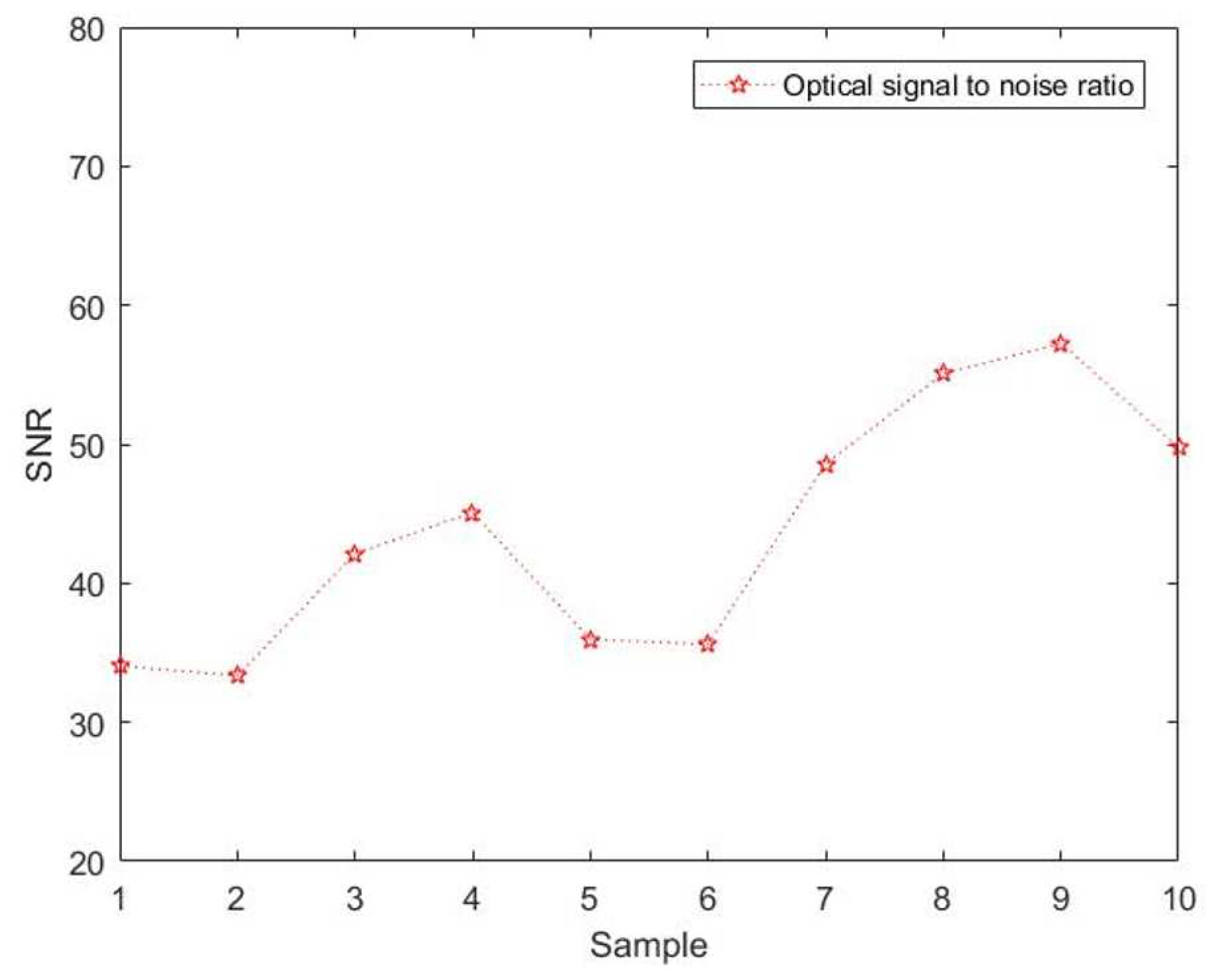
Figure 8, the processing speed and time requirements of equipment hardware is considered to improve the accuracy. Then, we introduce the signal-to-noise ratio. And then based on Equation (10-13), we do analyze the processing effect of this model proposed, as shown in
Figure 9. Apparently, the SNR for the 10 sample points obtained are not consistent and vary widely. Notably, the SNR after denoising all have been increased evidently. Namely, the noise reduction effect is fine here. In addition, the average value of SNR obtained has reached 43.6911dB, which has satisfied the demand. In particular, a larger SNR obtained indicates that the signal is the main component and the decomposition scale can be appropriately tuned down. On the contrary, the decomposition scale can be appropriately tuned up.
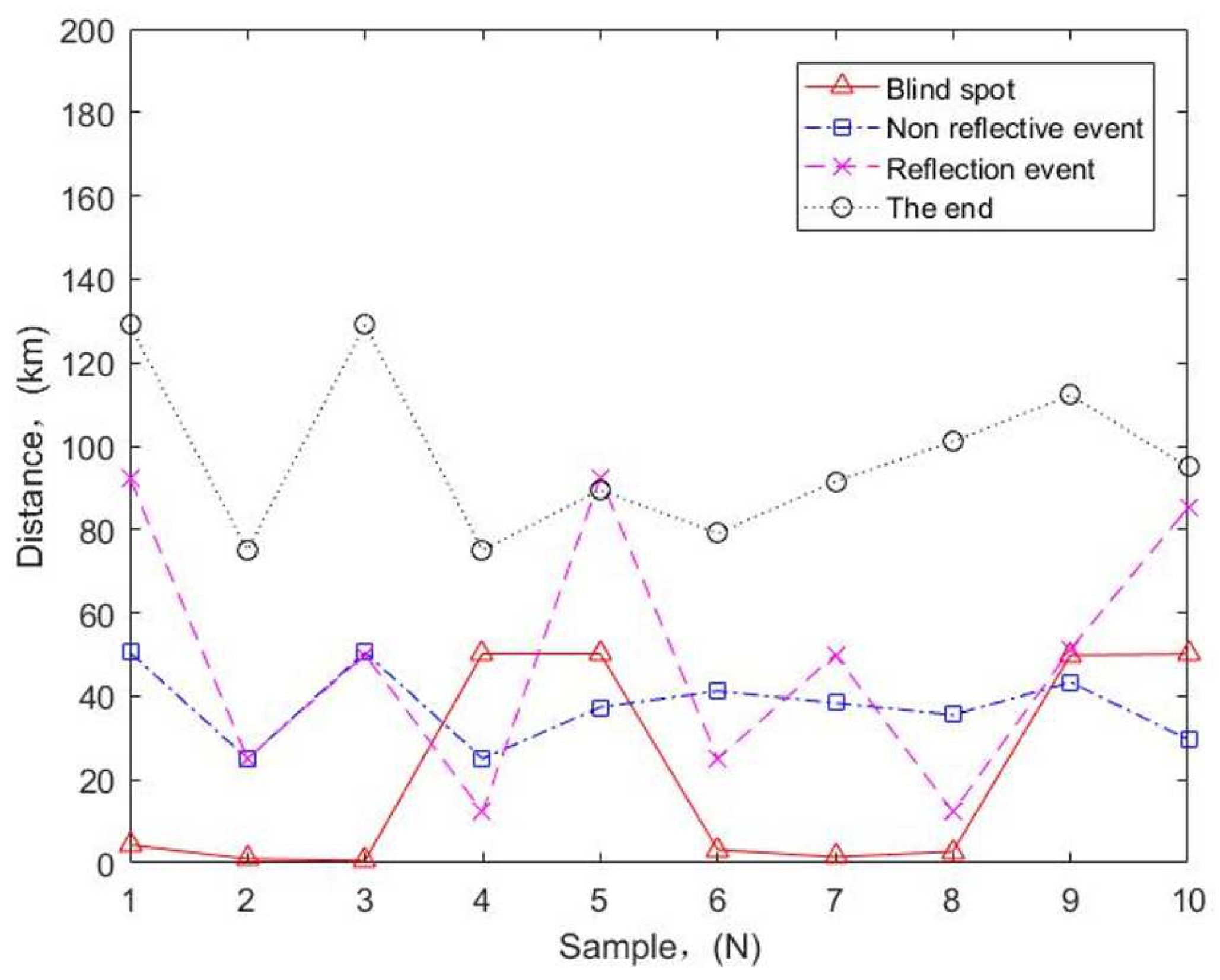
To verify the accuracy of the model proposed, we have conducted field tests at high altitudes and obtained a large number of experimental data. Combined with the second part of this paper and
Figure 5 and
Figure 7, the simulation results of the curve test events of OTDR are shown in
Figure 10. Obviously, the non-reflection events are relatively smooth, which indicates normal transmission of the optical signal, while the blind spot occasionally changes abruptly, which indicates increased reflection at this time and can seriously affect the accuracy of fiber length measurements. In particular, although the reflection event is not regular and contains Rayleigh scattering and Fresnel reflection, it is the core of fiber fault location detection. Here, the detection location and event type of events basically match with the actual situation, with high accuracy.
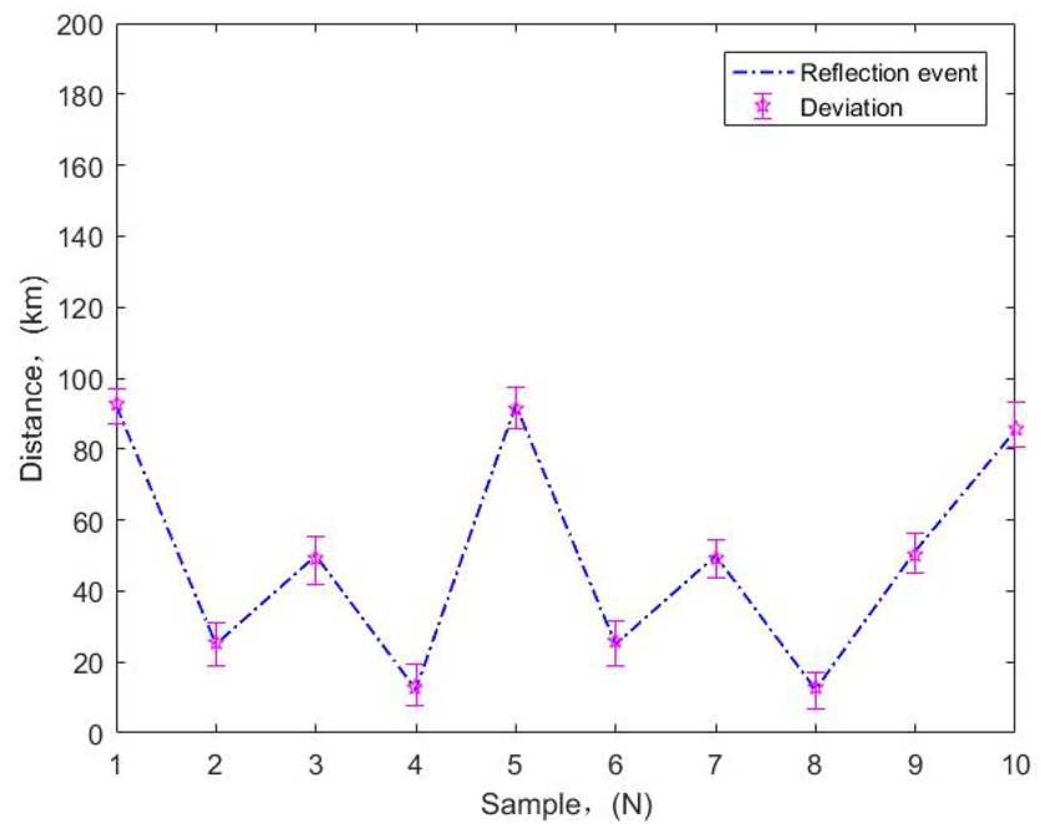
To further verify the accuracy of the model, we associate
Figure 10 to do further analysis of reflection events and obtain corresponding curves, as shown in
Figure 11. Obviously, despite the large fluctuations of the reflected events, there is no much deviation for each reflected event point, which indicates that the positions of checked reflected events basically match the positions of the actual reflected events, which again verifies the high accuracy of the model proposed. It is worth noting that, although there is no regularity in the detection of reflection events, it does not affect application of the method proposed to the event detection of large span, unrepeatered fiber optic links at high altitudes. For example, if the fault point is observed through OTDR curve, there is an obvious Fresnel reflection peak. Then, compared with the data, if the distance from a certain joint is close, it can be preliminarily judged as an optical fiber fault in the box. And if the distance between the fault point and the joint is large, it is a fault in the cable.
