Submitted:
31 July 2023
Posted:
02 August 2023
You are already at the latest version
Abstract
Keywords:
1. Introduction
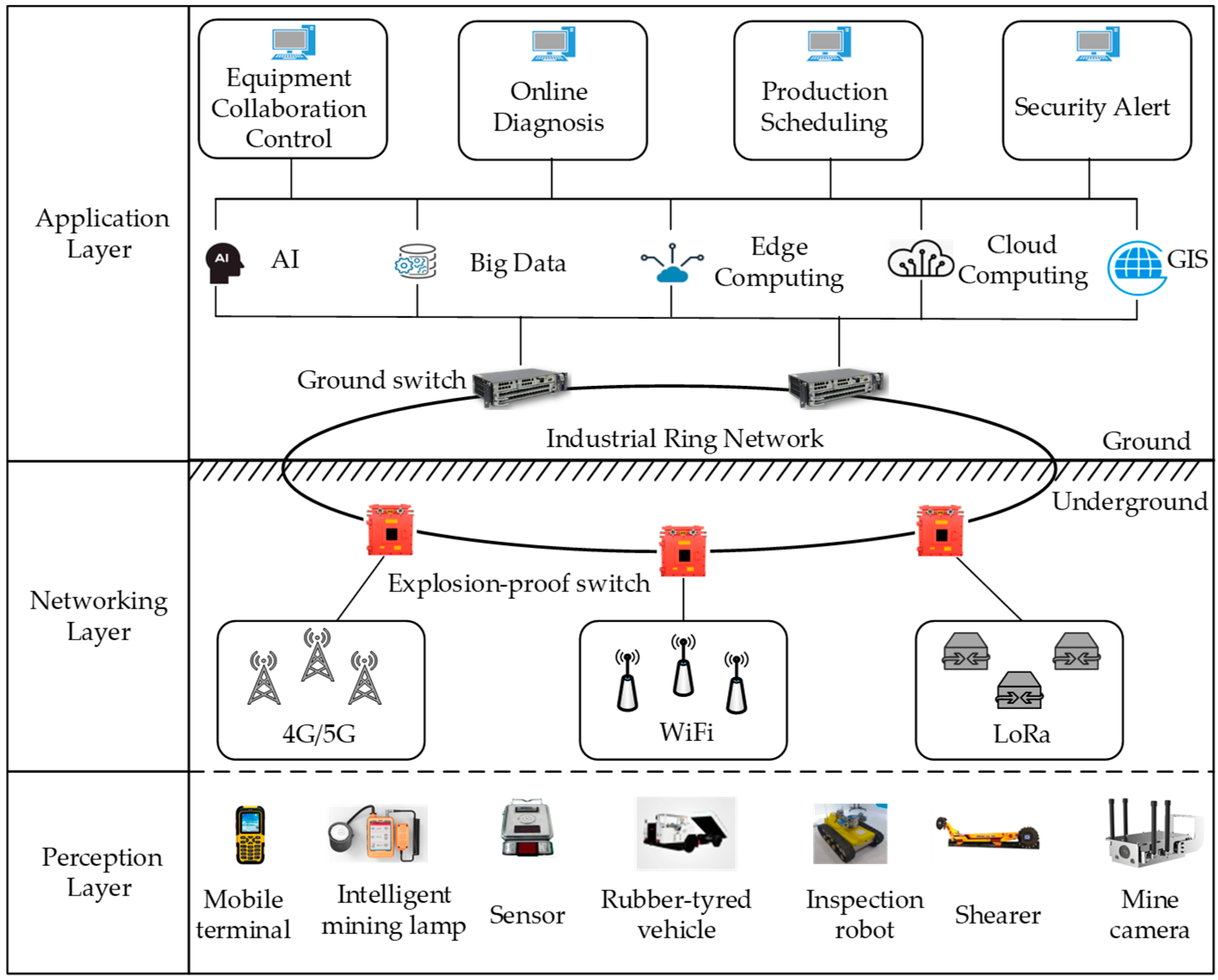
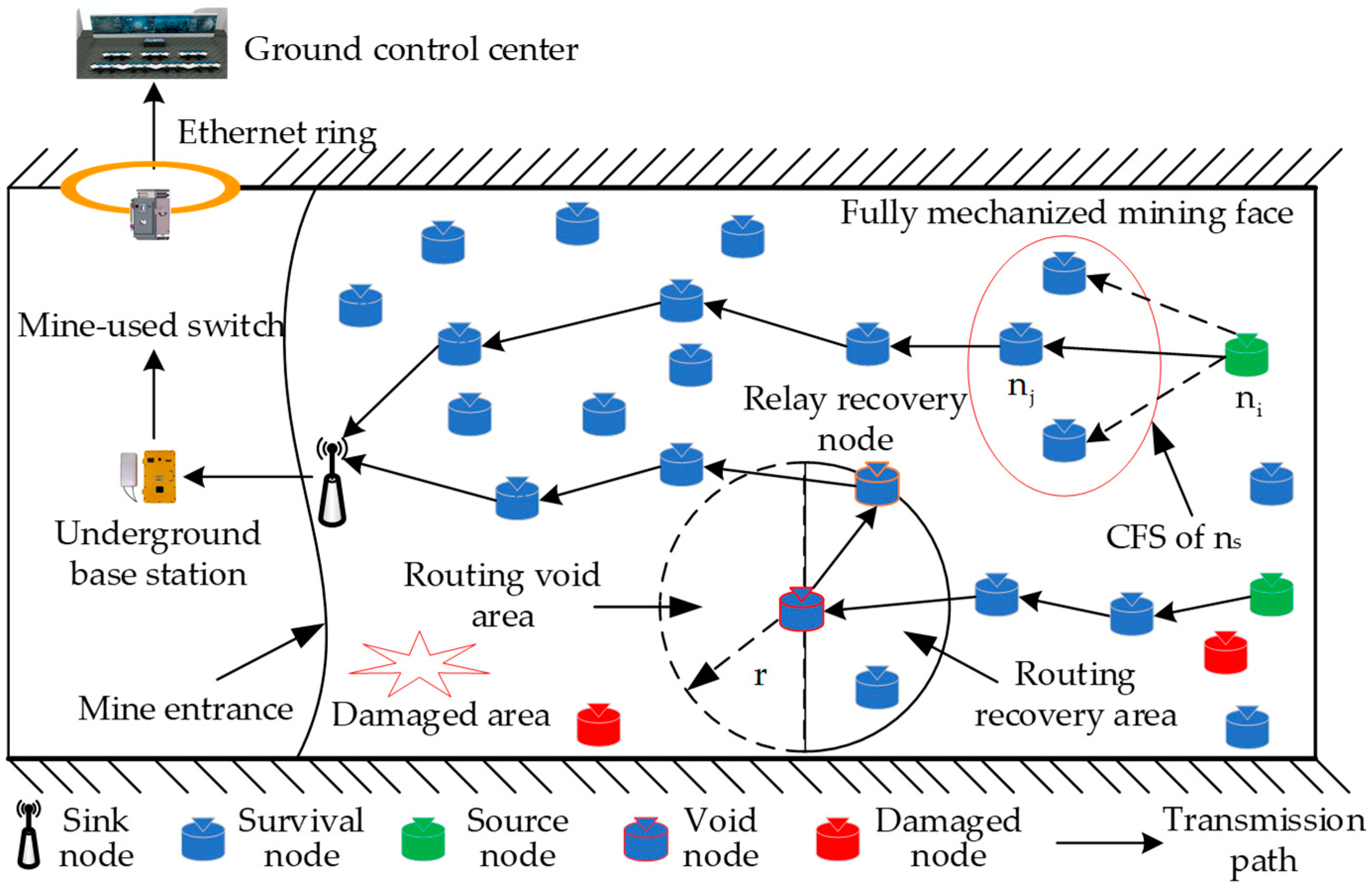
- In order to restore post-disaster data transmission of MIoT in the planar accident area rescue scenarios such as fully mechanized coal face, a post-disaster flat network architecture of MIoT based on multi-hop routing of surviving nodes is established, which consists of a sink node and multiple surviving sensor nodes. This network architecture achieves the purpose of comprehensive perception and effective transmission of environmental information in the planar accident mine after disasters.
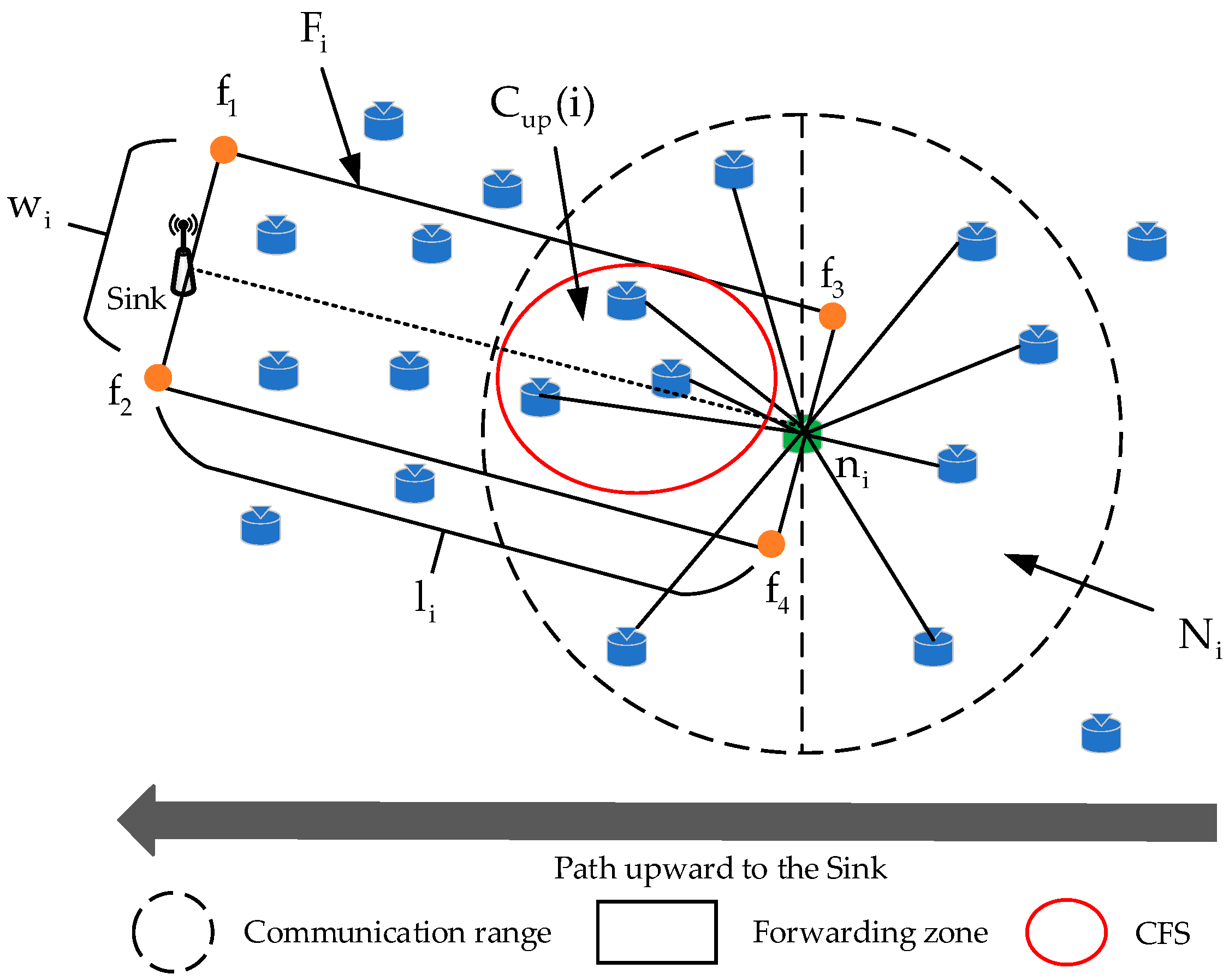
- We propose a directional-area-forwarding-based candidate forwarding set construction strategy. In the network initialization phase, according to the deployment density and communication radius of nodes in the accident roadway, a forwarding zone (FZ) is designed for each node to route packets toward the sink. Then, the candidate forwarding set (CFS) is constructed by the nodes within the FZ that satisfy the energy constraint and the neighboring node degree constraint. By restricting the number of duplicated packets in the network, DEOR improves the energy utilization of the nodes.
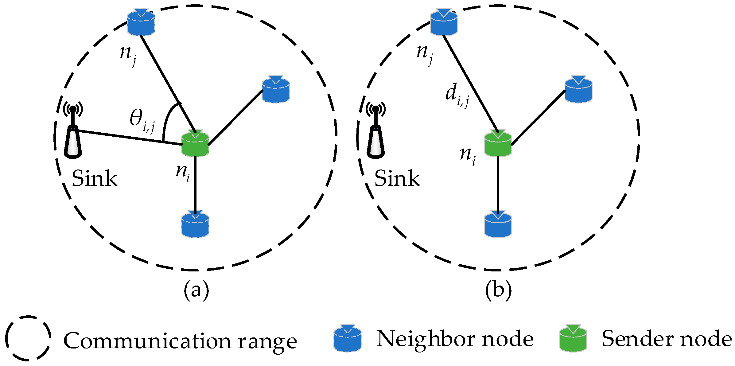
- We propose a relay nodes selection method based on routing quality evaluation. In the data transmission phase, we take multiple attributes of nodes into account, such as direction angle, transmission distance, and residual energy. Next, nodes in CFS are prioritized based on the routing quality and the forwarding node with the highest priority is selected as the relay node to forward packets. Other nodes in CFS discard packets after listening for a successful transmission message. By utilizing the collaboration between forwarders, DEOR addresses the hot-spot problem and balances the traffic load between nodes.
- We design a recovery mechanism for void nodes. When packets encounter the routing void during forwarding, a recovery mechanism is triggered. By employing the modified routing quality evaluation function, packets can bypass the void routing region and select available relay nodes to continue forwarding. DEOR overcomes the void routing node problem and improves the robustness of the whole network.
2. Related Work
2.1. MIoT Routing Protocols
| Protocol | Scenario | Node Status | Deployment | Routing metric | Features |
|---|---|---|---|---|---|
| RPAPC-MN[13] | Normal | Static & mobile | Partition | Area positive clustering | Reduce system energy consumption and extend network lifetime |
| DESR[14] | Normal | Static | Random | Transmission delay, packet loss rate and energy consumption | Ensure QoS requirements |
| LBDA[15] | Normal | Static | Uniform | The forwarding data traffic and forwarding nodes | Balancing node energy consumption and maximizing network lifecycle |
| SEC[16] | Post-disaster | Static | Random | Energy factor and connectivity factor | Extended network stability cycle, and improved network stability |
| EAUC[17] | Post-disaster | Static | Random | Energy and distance factors | Balancing cluster head energy consumption and improving data transmission |
| MVBN[18] | Post-disaster | Static | Random | The centrality of intermediate numbers, node compactness, and residual energy | Optimized network remaining energy, number of dominant nodes, and node coverage |
| NHCRA-O[19] | Post-disaster | Static & mobile | Random | Residual energy factor, node connectivity, and directional medium | Improve node matching efficiency and network coverage efficiency |
| RIAC[20] | Post-disaster | Static | Random | Residual energy, distance, and trust factor | Reduce inter-cluster transmission energy consumption |
2.2. Opportunistic Routing Protocols
3. System Model and Problem Description
3.1. Network Architecture
| Notation | Meaning |
|---|---|
| The network. is a sensor node. | |
| The neighbors set pf node . | |
| The size of , . | |
| The source node. | |
| The sink node. | |
| The initial energy of node. | |
| The transmission distance from the node to its neighbor . | |
| The direction angle between the node and towards the sink node. | |
| The residual energy of neighbor of . | |
| The Euler’s constant. Approx. 2.71828. | |
| The network density. | |
| The forwarding zone for the node | |
| The width of forwarding zone for the node | |
| The area of the target field. | |
| The communication range of node. | |
| The candidate forwarding zone of . | |
| The candidate forwarding set of . | |
| The control parameters of routing metrics. | |
| The routing quality of neighbor of . |
3.2. Energy Model
3.3. Problem Description
4. Proposed DEOR Algorithm
4.1. Construction of Candidate Forwarding Set
| Algorithm 1: Construct the Candidate Forwarding Set |
|
Input: Output: The candidate forwarding set 1: for each node do 2: Define the Forwarding Zone using Eq. (5) 3: Get the subset using Eq. (6) 4: end for 5: for each node do 6: Get the subset using Eq. (7) 7: Get the subset using Eq. (8) 8: if &&&& 9: then add 10: end if 11: end for 12: if 13: then 14: switch to Algorithm 3 15: else 16: switch to Algorithm 2 17: end if |
4.2. Selection of Relay Node
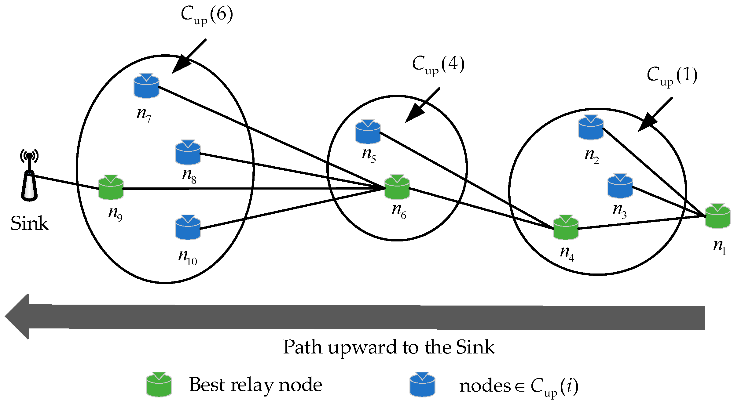
| Algorithm 2: Select the Best Relay Nodes |
| Input: Output: The ID of the best relay nodes 1: for each node do 2: node receives the packets sent by node 3: Get the using Eq. (12) 4: Get the using Eq. (15) 5: Get the using Eq. (17) 6: Calculate using Eq. (19) 7: sort in descending order to 8: end for 9: select the node from the highest - 10: if forwards the packet successfully 11: then other nodes in drop the packet 12: else 13: set the node = where has lower - 14: end if 15: until the timer expired 16: if packet is not delivered to Sink 17: then 18: switch to Algorithm 1 19: end if |
4.3. Recovery Mechanism
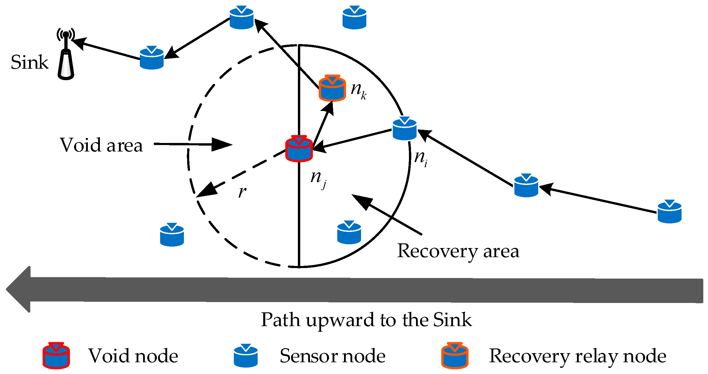
| Algorithm 3: Recovery Mechanism of Void Nodes |
|
Input: Output: The candidate recovery forwarding set 1: for each node do 2: Get the subset using Eq. (20) 3: Get the subset using Eq. (21) 4: if 5: then add 6: 7: end if 8: end for 9: switch to Algorithm 2 |
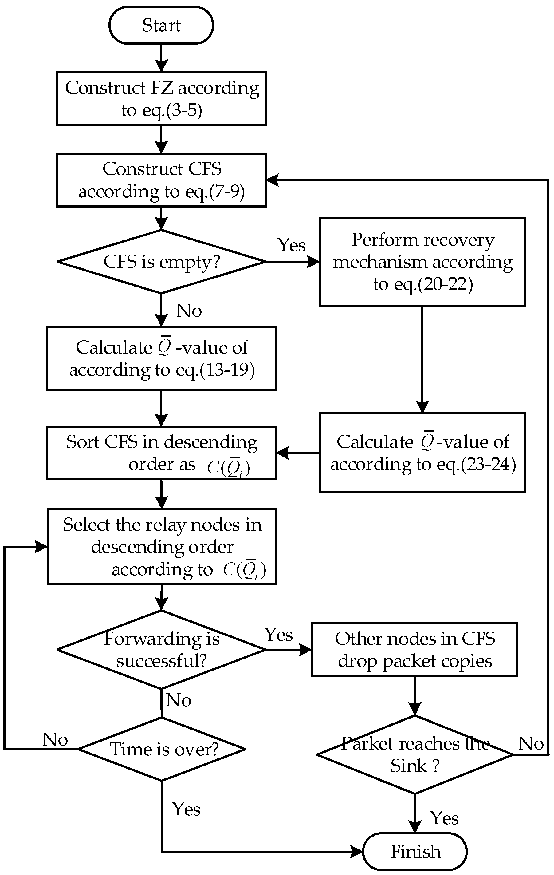
4.4. Analysis and Flowchart of DEOR
5. Performance Evaluation
5.1. Simulation Settings
| Parameters | Valus |
|---|---|
| Network topology | Random |
| Deployment area | |
| Generate rate | 1packet/0.1s |
| Number of nodes Sink |
200-300 1 static sink (edge) |
| Transmission rate | 1Mbps |
| Communication range | 40m |
| Simulation time | 2000s |
| RF channels | 2.4GHz |
| Packet size Initial energy Sleep power |
1020bits 0.5J 0.78mW |
|
|
|
5.2. Effect of Control Parameters
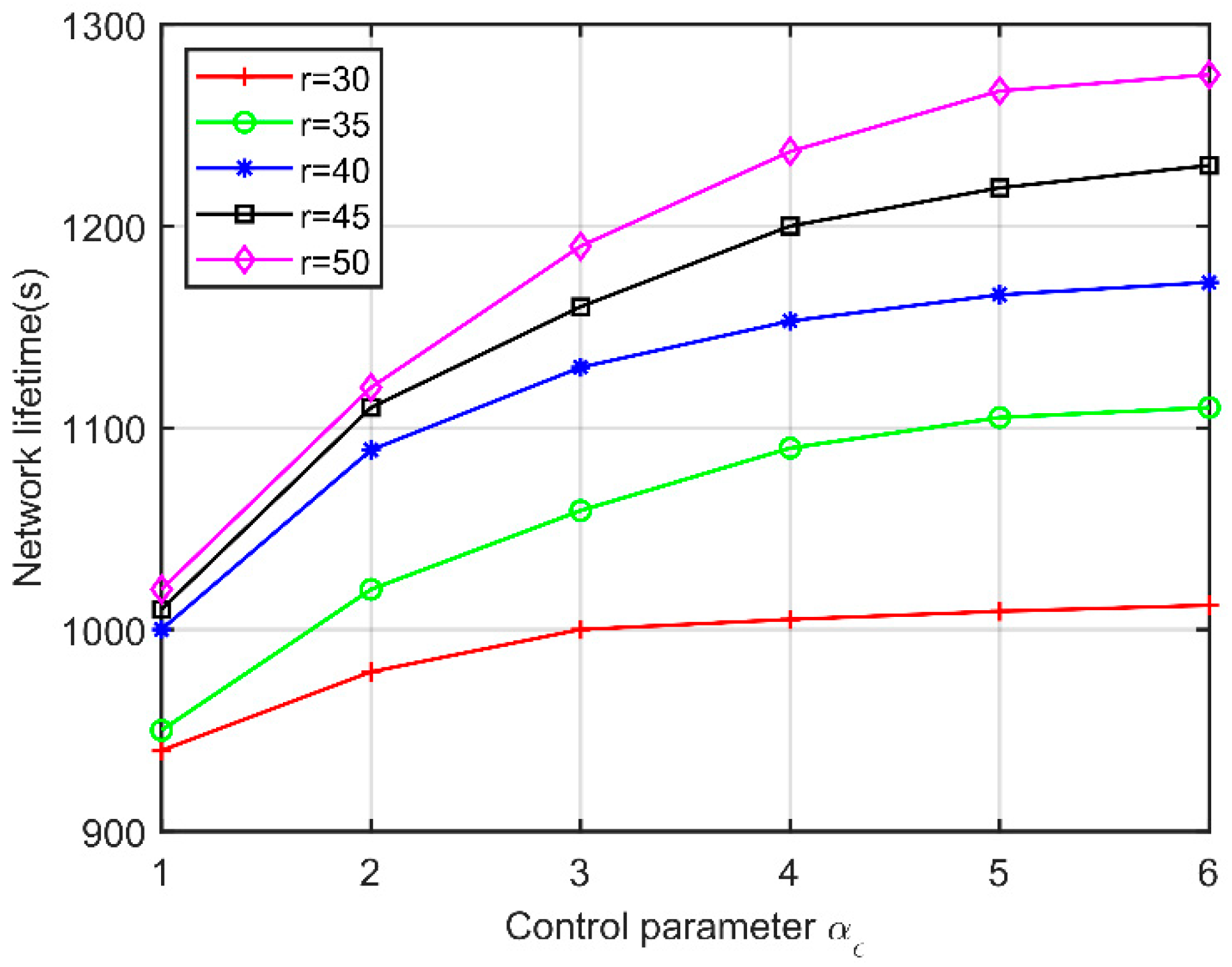
5.3. Performance for Varying Communication Ranges
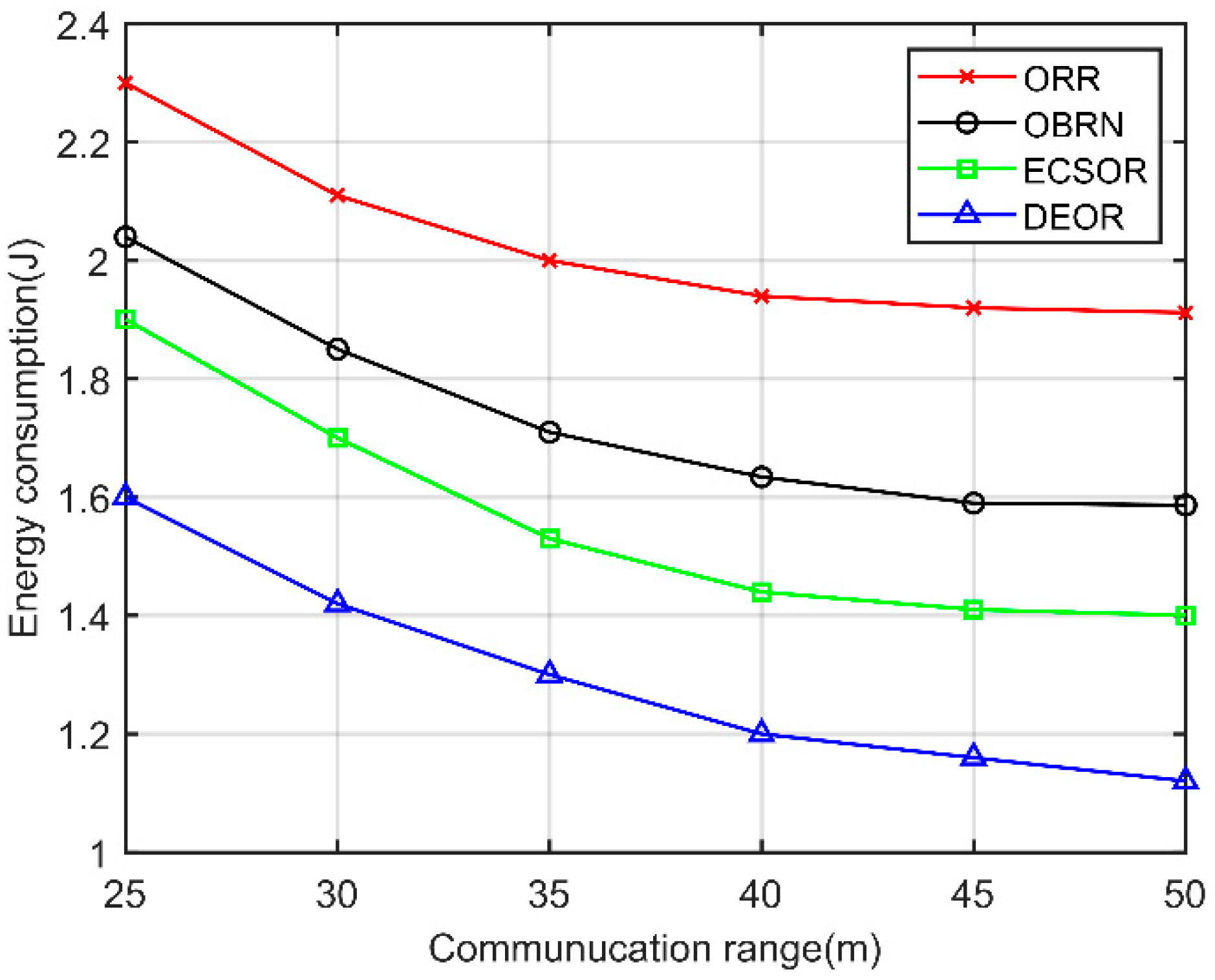
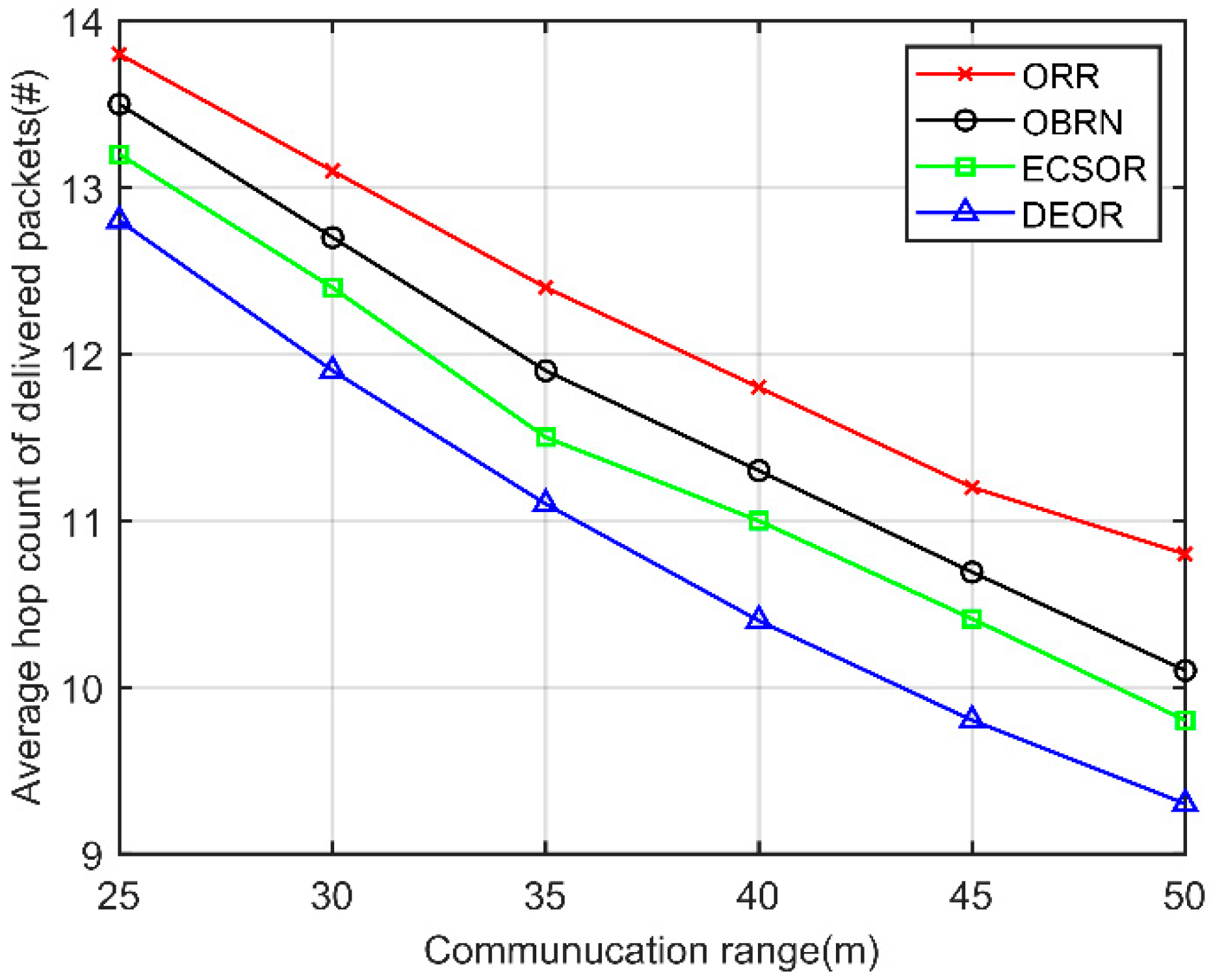
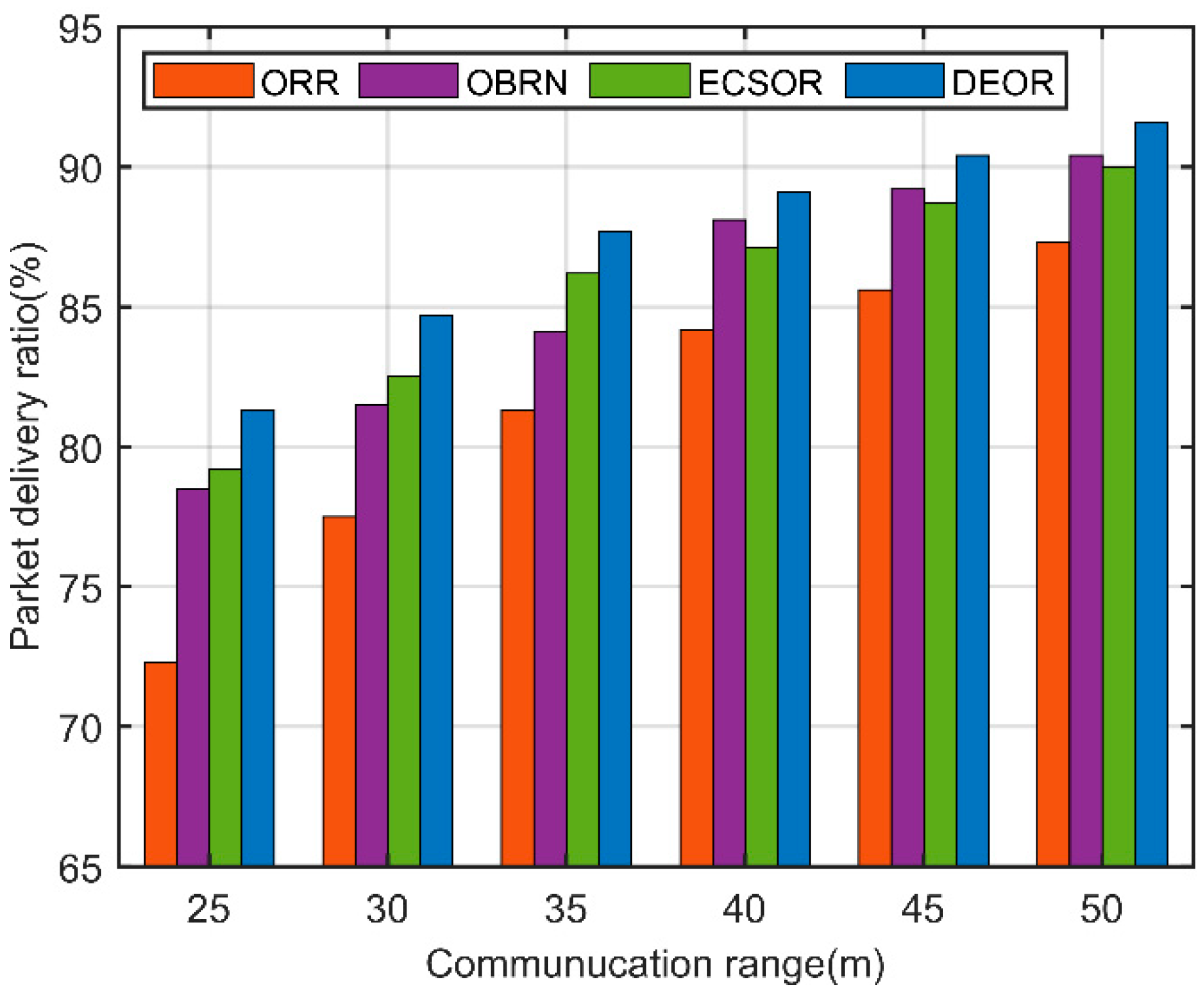
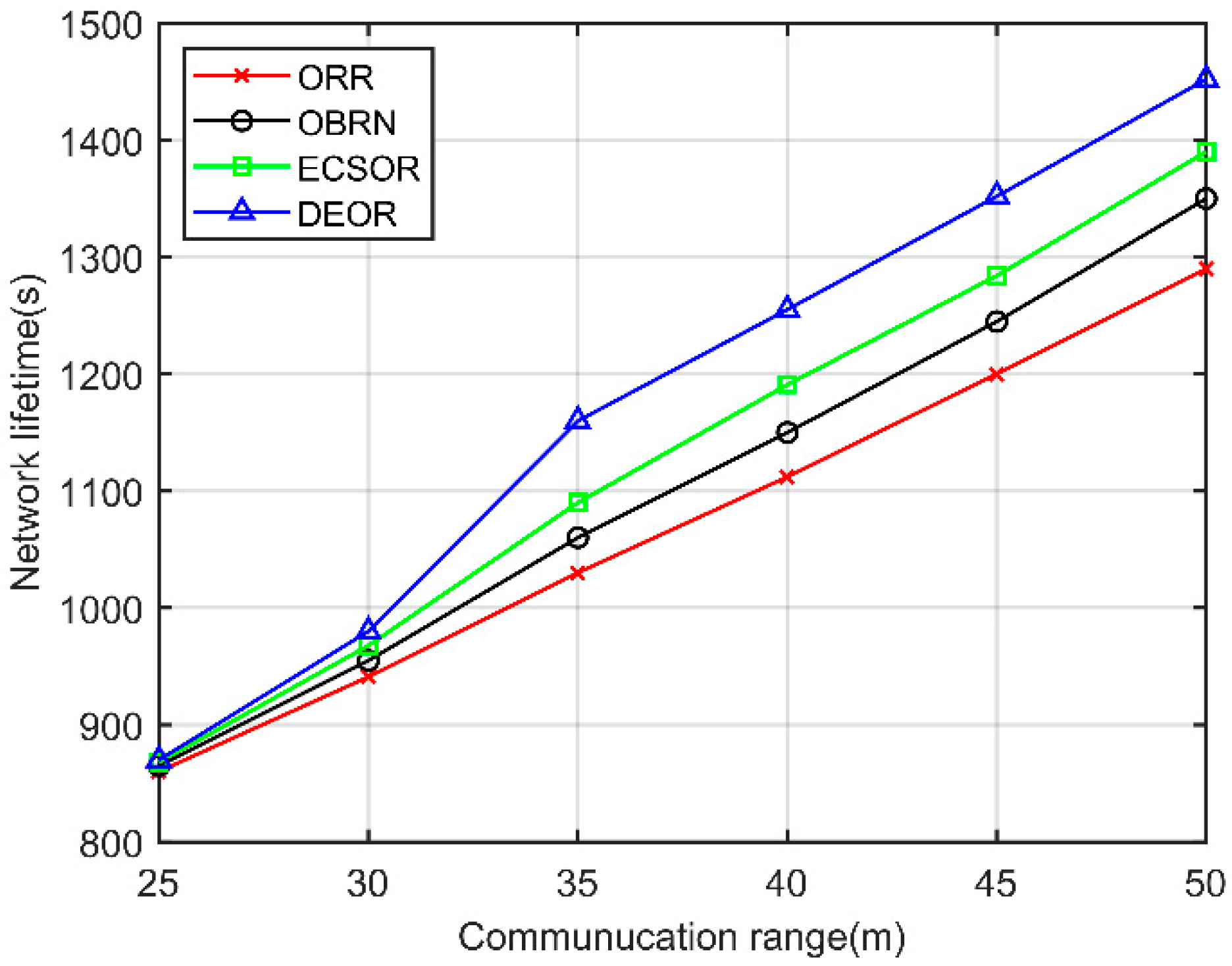
5.3. Performance for Varying Number of Nodes
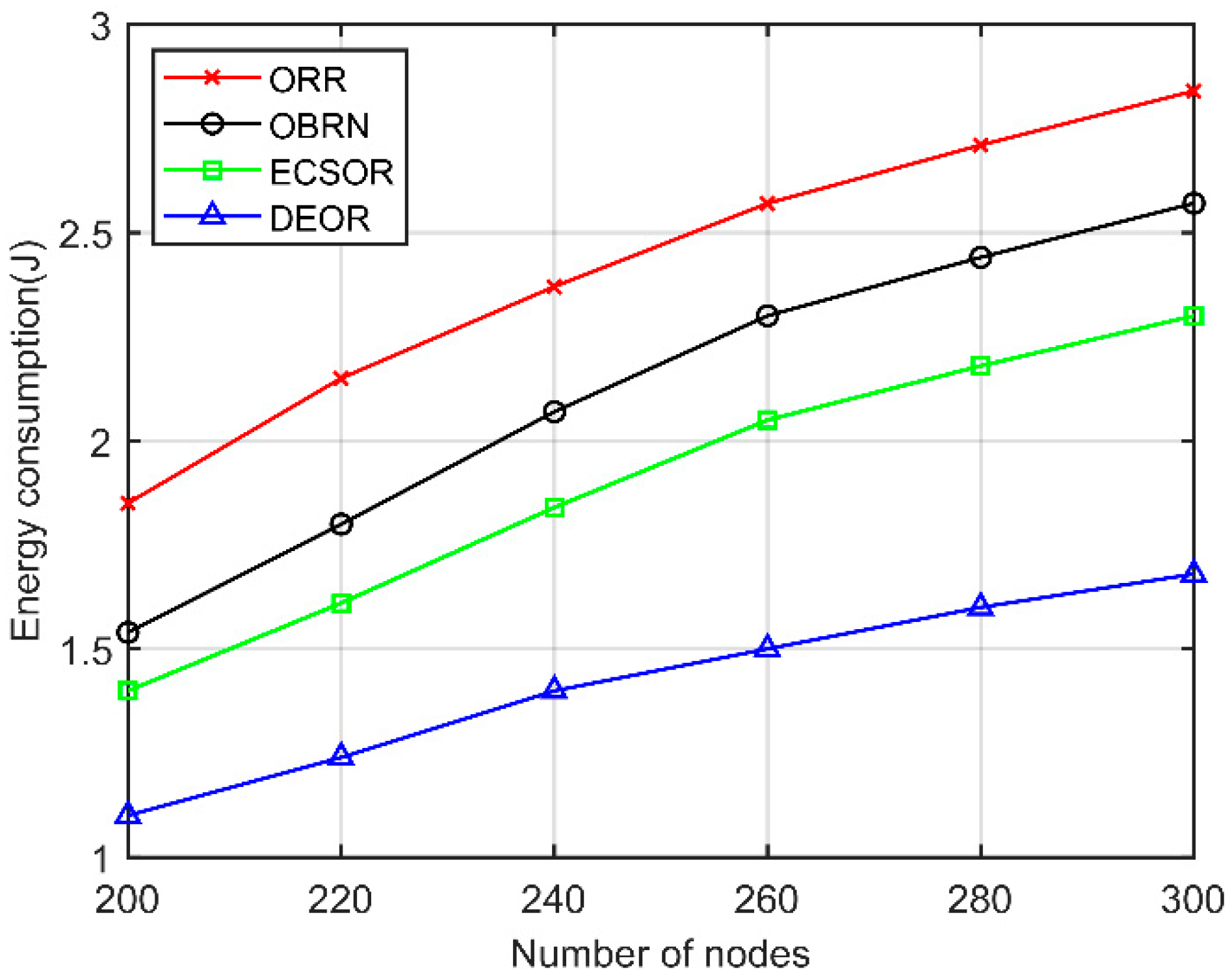
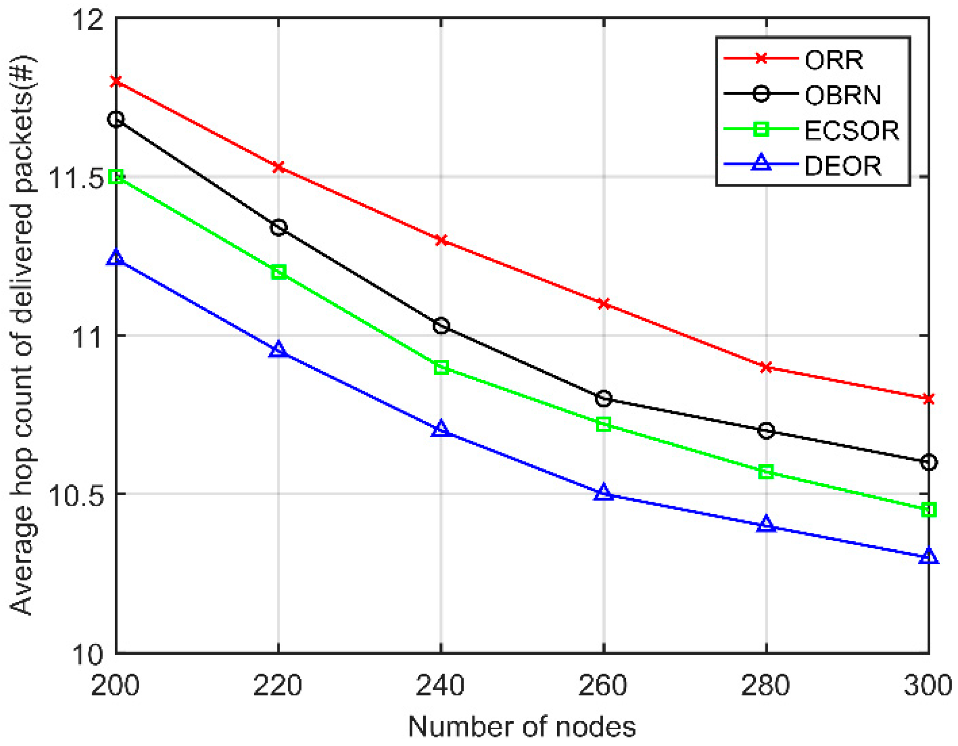
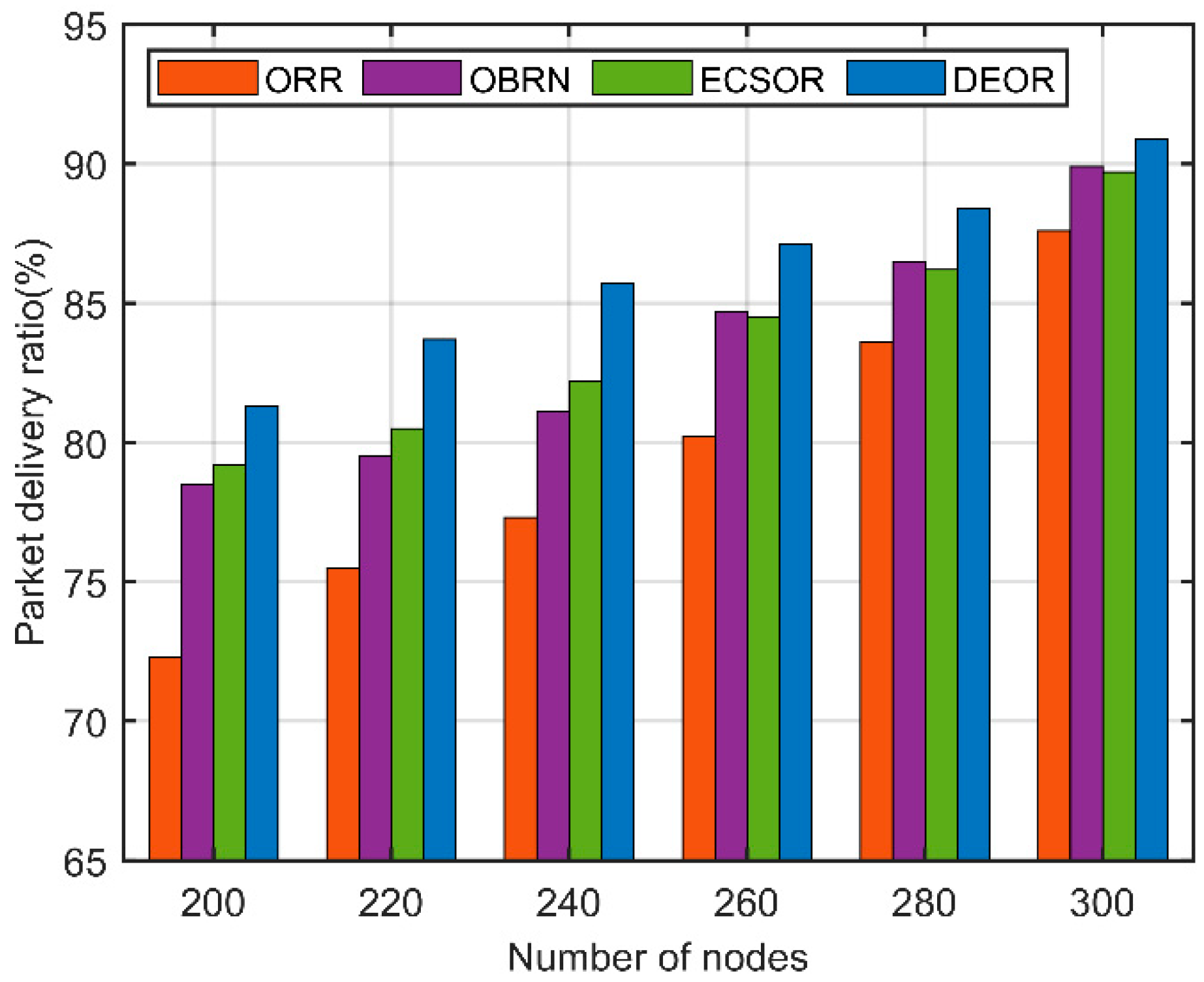
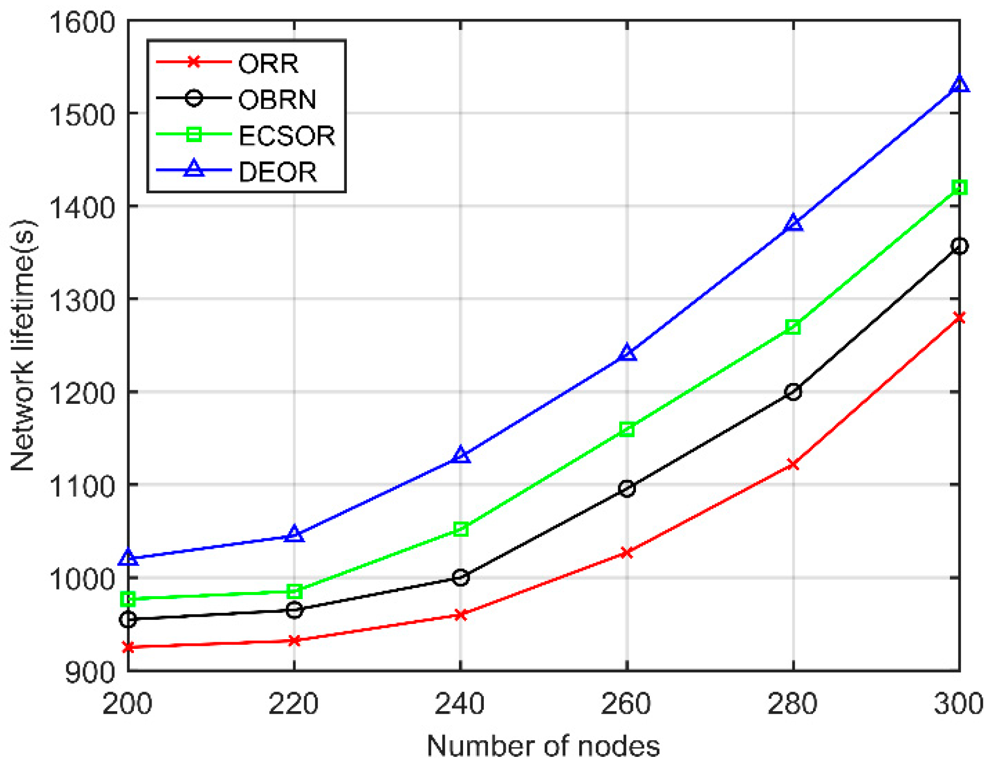
6. Conclusions
Author Contributions
Funding
Institutional Review Board Statement
Informed Consent Statement
Data Availability Statement
Conflicts of Interest
References
- Sun, J.P. New technology and development of mine informatization and automation. Coal Science and Technology, 2016, 44, 19-23+83.
- Yuan, L. Framework and key technologies of Internet of things for precision coal mining. Industry and Mine Automation, 2017, 43, 1-7.
- Li, S.G.; Ma, L.; Yang, S.G. Key technology and application framework of internet plus mine safety informationization. Coal Science and Technology, 2016, 44, 33-40.
- Sun, J.P. Accident analysis and big data and Internet of Things in coal mine. Industry and Mine Automation, 2015, 41, 1-5.
- Zheng, X.Z.; Tong, X.; Guo, J.; Zhang, D. Research status and development trend of intelligent monitoring and early warning technology in coal mine. Industry and Mine Automation, 2020, 46, 35-40.
- Sun, J. P.; Qian, X.H. Emergency rescue technology and equipment of mine extraordinary accidents. Coal Science and Technology, 2017, 45, 112-116+153.
- Sun, J. P.; Zhang, G.M. Mine emergency communication system. Industry and Mine Automation, 2019, 45, 1-5.
- Hu, Q. S.; Yang, W.; Ding, E.J.; Li, S.Y.; Li, B.H. State-of-the-art and trend of emergency rescue communication technologies for coal mine. Journal on Communications, 2019, 40, 163-179.
- Xu, Y.Y.; Yang, W.; Hu, Q.S. An autonomous discovery mechanism of surviving IoT devices for post-disaster coal mine cellular IoT. Journal of China Coal Society, 2019, 44, 800-807.
- Chakchouk, N. A survey on opportunistic routing in wireless communication networks. IEEE Commun. Surveys Tuts., 2015, 17, 2214–2241. [CrossRef]
- Wu, W.; Wang, X.; Hawbani, A.; Liu, P.; Zhao, L.; Al-Dubai, A. FLORA: Fuzzy Based Load-Balanced Opportunistic Routing for Asynchronous Duty-Cycled WSNs. IEEE Transactions on Mobile Computing, 2023, 22, 253-268. [CrossRef]
- Yang, X.; Xu, Y.; Wang, D.; Hua, G. Virtual-Range-Forwarding-Based Opportunistic Routing for Mine Goaf Sensor Networks. IEEE Sensors Journal, 2022, 22, 22244-22254. [CrossRef]
- Yu, X.W.; Zhang, K.; Zhou, X.L.; Zhang, F.; Liu, Q.; Hu, F.M. Routing Protocol in Mine Roadway Based on Area Positive Clustering and Mobile Nodes. Information and Control, 2018, 47, 379-384.
- You, K.M.; Yang, W.; Yuan, X.X.; Wang, P.Y. Differentiated services routing protocol of WMSNs for underground coal mines. J.Huazhong Univ.of Sci.& Tech. (Natural Science Edition), 2018, 46, 1-8.
- Wu, B.; Zhou, X.; Huang, Q. Optimal Data Routing Algorithm for Mine WSNs Based on Maximum Life Cycle. IEEE Access, 2020, 8, 131826-131834. [CrossRef]
- Wu, T.; Yang, W.; Wang, Y.P. Self-organized energy-efficient clustering protocol for post-disaster reconstruction network of coal mine IoT. J.Huazhong Univ.of Sci.& Tech. (Natural Science Edition), 2020, 48, 7-13.
- Zhao, Q.; Yang, W.; Hu, Q.S. Adaptive uneven clustering algorithm for post-disaster reconstruction of coal mine IoT. J.Huazhong Univ.of Sci.& Tech. (Natural Science Edition), 2021, 49, 120-126.
- Hu, Q.S.; Wang, N.S. Post-disaster reconstruction algorithm of wireless ad hoc network in coal mine. Industry and Mine Automation, 2022, 48, 93-99.
- Hu, Q.S.; Fan, X.G.; Li, H. Network hole coverage reconstruction algorithm for post-disaster coal mine Internet of things. Industry and Mine Automation, 2022, 48, 39-45.
- Chen, Z.G. Research on Clustering Routing Protocol of Coal Mine Emergency Rescue Network. China University of Mining and Technology, China, 2022.
- Dalal, R.; Khari, M.; Anzola, J.P.; García-Díaz, V. Proliferation of Opportunistic Routing: A Systematic Review. IEEE Access, 2022, 10, 5855-5883. [CrossRef]
- Sang, Q.; Wu, H.; Xing, L.; Ma, H.; Xie, P. An Energy-Efficient Opportunistic Routing Protocol Based on Trajectory Prediction for FANETs. IEEE Access, 2020, 8, 192009-192020. [CrossRef]
- Li, N.; Yuan, X.; Martinez-Ortega, J.-F.; Diaz, V.H. The Network-Based Candidate Forwarding Set Optimization for Opportunistic Routing. IEEE Sensors Journal, 2021, 21, 23626-23644. [CrossRef]
- Zhao, Y.; Srivastava, G. A Wireless Mesh Opportunistic Network Routing Algorithm Based on Trust Relationships. IEEE Access, 2022, 10, 4786-4793. [CrossRef]
- Li, N.; Yan, J.; Zhang, Z.; Martínez-Ortega, J.-F.; Yuan, X. Geographical and Topology Control-Based Opportunistic Routing for Ad Hoc Networks. IEEE Sensors Journal, 2021, 21, 8691-8704. [CrossRef]
- Banyal, S.; Bharadwaj, K.K.; Sharma, D.K.; Khanna, A.; Rodrigues, J. J. P. C. HiLSeR: Hierarchical learning-based sectionalized routing paradigm for pervasive communication and resource efficiency in opportunistic IoT network. Sustain. Comput., Informat. Syst., 2021, 30, 100508. [CrossRef]
- Celik, A.; Saeed, N.; Shihada, B.; Al-Naffouri, T.Y.; Alouini, M.-S. Opportunistic Routing for Opto-Acoustic Internet of Underwater Thing. IEEE Internet of Things Journal, 2022, 9, 2165-2179. [CrossRef]
- Zhou, X.; Yang, X.; Ma, J.; Wang, K.I.-K. Energy-Efficient Smart Routing Based on Link Correlation Mining for Wireless Edge Computing in IoT. IEEE Internet of Things Journal, 2022, 9, 14988-14997. [CrossRef]
- Li Q.; Zhang, L.; Zeng, F.; Pan, Y.; Yang, J. Community Clustering Routing Algorithm Based on Information Entropy in Mobile Opportunity Network. IEEE Access, 2022, 10, 25755-25766. [CrossRef]
- Zhang, H.N. Research on Re-localization Method of Drift Nodes after Coal Mine Disaster. China University of Mining and Technology, China, 2021.
- Cheng, Y. Research on Relocation Method of Drift Node in Coal Mine. China University of Mining and Technology, China, 2020.
- Liang, Y.; Wei, Z.; Chen, Q.; Wu, H. Neighbor Discovery Algorithm in Wireless Ad Hoc Networks Based on Successive Interference Cancellation Technology. 2020 International Conference on Wireless Communications and Signal Processing (WCSP), Nanjing, China, 2020, 1137-1141. [CrossRef]
- Sorribes, J.V.; Peñalver, L.; Calafate, C.T.; Lloret, J. Collision-Aware Deterministic Neighbor Discovery in Static Ad Hoc Wireless Networks. 2020 Global Conference on Wireless and Optical Technologies (GCWOT), Malaga, Spain, 2020, 1-8. [CrossRef]
- Heinzelman, W.R.; Chandrakasan, A.; Balakrishnan, H. Energy efficient communication protocol for wireless microsensor networks. Proc. 33rd Annu. Hawaii Int. Conf. Syst. Sci., 2000, 10.
- Santi, P. Topology control in wireless ad hoc and sensor networks. ACM Comput. Surveys, 2005, 37, 164-194. [CrossRef]
- Sivrikaya, F.; Geithner, T.; Truong, C.; Khan, M.A.; Albayrak, S. Stochastic routing in wireless sensor networks. Proc. IEEE Int. Conf. Commun. Workshops, 2009, 1–5. [CrossRef]
- Singh, A.; Kumar, D.; Hötzel, J. IoT Based information and communication system for enhancing underground mines safety and productivity: Genesis, taxonomy and open issues. Ad Hoc Networks, 2018, 78, 115-129. [CrossRef]
- Hawbani, A.; Wang, X.F.; Abudukelimu, A.; Kuhlani, H.; AI-Sharabi, Y.; Qarariyah, A.; Ghannami, A. Zone probabilistic routing for wireless sensor networks. IEEE Trans. Mobile Comput., 2019, 18, 728–741. [CrossRef]
- So, J.; Byun, H. Load-balanced opportunistic routing for duty-cycled wireless sensor networks. IEEE Trans. Mobile Comput., 2017, 16, 1940–1955. [CrossRef]
- Padyal, R.H.; Kadam, S.V. Continuous neighbor discovery approach for improvement of routing performance in WSN. 2017 2nd International Conference for Convergence in Technology (I2CT), India, 2017, 675–679.
- Fradj, H.B.; Anane, R.; Bouallegue, R. Energy consumption for opportunistic routing algorithms in WSN. 2018 IEEE 32nd International Conference on Advanced Information Networking and Applications (AINA), Poland, 2018, 259–265.
Disclaimer/Publisher’s Note: The statements, opinions and data contained in all publications are solely those of the individual author(s) and contributor(s) and not of MDPI and/or the editor(s). MDPI and/or the editor(s) disclaim responsibility for any injury to people or property resulting from any ideas, methods, instructions or products referred to in the content. |
© 2023 by the authors. Licensee MDPI, Basel, Switzerland. This article is an open access article distributed under the terms and conditions of the Creative Commons Attribution (CC BY) license (http://creativecommons.org/licenses/by/4.0/).


