Preprint
Article

Absorber Enrichment and Its Implication on the Performance of Lead-free CsSnI3 Perovskite Solar Cells (PSCs) - A 1D-SCAPS Study

Altmetrics

Downloads

310

Views

144

Comments

0

A peer-reviewed article of this preprint also exists.

Submitted:

30 July 2023

Posted:

01 August 2023

You are already at the latest version

Alerts
Abstract
One-Dimensional Solar Cell Capacitance Simulator (1D-SCAPS) and n-i-p planar configuration have been employed for the simulation of the caesium tin iodide (CsSnI3)-based perovskite solar cell (PSC) with titanium (IV) oxide (TiO2) and copper thiocyanate (CuSCN) as the electron and hole transport materials respectively. The results obtained for the initially modeled PSC compared well with similar devices in the literature but marred with high recombination rate. As such, the defect density in the CsSnI3 absorber was varied from 1013 cm-3 to 1017 cm-3 and enriched with SnCl2 (additive) and Br(dopant) respectively. This strategy ensured a reduced concentration of Sn4+ vacancy (VSn) in the CsSnI3 absorber with improved carrier lifetime and diffusion length beyond 0.05 ns and 1.1µm by a magnitude of the order of 103 and 102 respectively for the enriched CsSnI3 –based PSC. For the optimized PSC, we recorded VOC=1.289 V, JSC=32.60 mA.cm-2, FF=83.56% and PCE=35.12%.
Keywords: 
Subject: Physical Sciences  -   Condensed Matter Physics

1. Introduction

The conversion of sunlight into electricity through photovoltaic (PV) effect using solar cells stands out as a potential solution to the future global energy crisis and environmental pollution brought about by energy generation from fossil fuel and natural gas [1,2,3]. The capacity of globally installed PV devices has been increasing over the last two decades. In 2020, the globally installed PV capacity amounted to 788 GW, with 183 GW and 191GW of new PV capacity installed in 2021 and 2022 respectively. This would amount to 1.5 TW if over 350.6 GW were to be installed in 2023 [4,5]. This indicates that the first generation silicon solar cells and the second generation thin film technologies are not only widely accepted but have also dominated the global PV markets [5,6]. Although, these solar cells have power conversion efficiency (PCE) of more than 26% and a lifespan of about 25 years, they are however characterized by high cost and difficult preparation conditions [6,7]. Amongst the third generation solar cells, perovskite solar cells (PSCs) have attracted significant attention due to lower material costs and low-temperature solution processing. Thus, making their fabrication procedures easy and cost-effective [7]. A typical PSC consists of an absorber material sandwiched between an electron transport material (ETM) and a hole transport material (HTM). The ETMs that are most commonly used in PSCs are n-type semiconductors such as TiO2, ZnO and PCBM [8,9,10,11] while the HTMs that are most commonly used are organic p-type polymers such as spiro-OMeTAD, PTAA, P3HT and PEDOT:PSS [10,12,13,14].
Reports have shown that PSCs offer PCE of 25.2% which is comparable to those of Si and thin-film solar cells [7,15,16]. The unique optical and electronic properties of perovskites are responsible for the improvement in their performance [17]. However, despite the large efficiencies recorded, the organic hole transport materials (HTMs) used in conjunction with the perovskite (absorber) are responsible for their instability and increased processing costs [18].
In addition, organic HTMs are also susceptible to degradation over time under humidity due to external doping usually done to guarantee optimum PCE in PSCs [19]. No doubt these shortcomings of organic HTMs pose as obstacle to large-scale commercialization of PSCs, as such the search for efficient and cost effective HTM calls for the use of inorganic HTMs to enhance the life time of PSCs and reduce the fabrication cost simultaneously. Prior reports showed that inorganic HTMs such as CuI and Cu2O have exhibited good mechanical and chemical stabilities with encouraging stable PCEs [20,21,22]. However, copper thiocyanate (CuSCN) proved to be a better alternative inorganic HTM compared with CuI and Cu2O as a result of its improved stability and distinct chemical robustness arising from its polymeric structure [23,24,25,26]. CuSCN is an inorganic p-type semi-conductor which exists in two forms as α-CuSCN and β-CuSCN with β-CuSCN being readily available and more thermally stable. In addition to these, it possesses compatible and easy solution processing ability, chemical stability, and high-optical transparency [27]. Comparative cost and performance analyses showed CuSCN to be the right replacement for organic HTMs amongst various HTMs according to [18]. Over the years the PCE for CuSCN-based PSCs have increased from 12.4% [28] through 17.0% for pristine absorber and CuSCN films obtained via spray deposition [29] to 18% for low temperature solution processed CuSCN [30]. To date, research efforts are in progress to take the PCE for PSCs up to and beyond the maximum theoretical limit of efficiency formulated by Shockley–Queisser [31,32]. Consequently, research efforts centered on theoretical modeling of CuSCN-based PSCs have been carried out to optimized their performance by varying the thickness, defect density, and effective valence band density of the absorber layer using SCAPS software [33,34,35,36]. Recently, the significance of shallow doping and diffusion length of absorber layer, valence band and conduction band offsets of the various active layers and interface defects was pointed out as being critical to the performance of PSCs. A thorough investigation vis-à-vis optimization of these critical factors was carried out with 1D-SCAPS leading to an optimized PCE of 25.20% for PSC using lead-based perovskite with CuSCN and TiO2 as HTM and ETM respectively [18].
Due to environmental concerns and stringent conditions imposed on the use of lead material for electronic and PV devices, significant research efforts have been directed toward replacing lead with similar metals having comparable electronic and optical properties for the engineering of alternative metallic based halide perovskite [37,38]. Accordingly, Ag+, Bi3+, Sb3+, Ti4+, Ge2+, and Sn2+ have been proposed as replacement for lead because they are less toxic and possess comparable properties as lead [39,40,41,42,43]. Amongst the various alternatives, tin based organic halide perovskites such as CH3NH3SnI3 (MASnI3), HC(NH2)2SnI3 (FASnI3) have been considered more suitable for PSCs partly because tin belongs to the same group as lead and due to the record PCE reported for PSCs with tin based organic halide perovskites as absorber layers [28]. However, PSCs based on MASnI3 and FASnI3 have been found to be chemically unstable because the organic cations therein react with water molecules to form weak hydrogen bonds that degrade device upon longtime exposure to moisture, heat and light [44,45]. Recently, metallic based halide perovskites with Cs+ cation have been investigated and found to be nontoxic with improved optoelectronic properties [46,47]. Among the cesium based metallic halide perovskites, reports have shown CsSnI3 to possess exceptional electrical and optical properties [48,49,50,51,52,53,54,55,56,57,58]. CsSnI3 is a unique material that exhibits four polymorphs with two of them existing independently at room temperature. One of the room temperature phases is yellow (Y) with a one-dimensional double-chain structure and the other phase is black (B-γ) with a three-dimensional perovskite structure [59]. The black perovskite CsSnI3 displays p-type metallic conductivity with unusually high conductivity when heat-treated and optical band gap of 1.3eV [49,59]. The ability of CsSnI3 to emit strong near-infrared photoluminescence at room temperature has been attributed to the readily changing Sn vacancy centers in the structure [49]. This rare characteristic would present opportunity to discover visible and IR light-emitting materials at room temperature, suitable for achieving ground breaking applications in photovoltaics, radiation detectors, and light-emitting diodes because the perovskite structure can incorporate a broad range of elements [60].
In the light of the above and to eliminate the factors hindering the commercialization of PSCs, it is therefore of paramount importance to consider cesium tin iodide (CsSnI3) as a replacement for lead-based perovskite in the engineering of PSCs with a strong focus on the optimization of critical physical factors that have direct influence on the PCE. The most urgent challenge of the CsSnI3-based perovskite solar cell is their low VOC, which is far behind the bandgap of CsSnI3 perovskite (1.3eV). This is mainly due to the severe charge recombination and band alignment mismatch at the absorber layer and its interfaces with the transport layers. These limiting factors have been the main obstacle to the efficiency improvement of CsSnI3-based perovskite solar cells. To further explore the photovoltaic potential of CsSnI3-based perovskite solar cells, the most important task is to minimize charge carrier recombination by enriching the absorber layer. In this paper, a detailed and systematic investigation of a modeled PSC consisting of TiO2 as ETM layer, CsSnI3 as absorber layer and CuSCN as HTM layer has been carried out with emphasis on enrichment of absorber layer with a view to optimizing the device performance.

2. Theory

2.1. Theoretical Details

The transport of charge carriers through the perovskite absorber to the respective transport layers in a PSC is governed by the Poisson’s equation and the continuity equations for electrons and holes as is the case of semiconductor [61]. Under solar light irradiation with a power intensity of Pin, the photogenerated charge carriers will flow inside the PSC in accordance with the continuity equations and their dynamics is governed by the following rate equation:
d n d t = G U
where n is the concentration of charge carriers, G is the charge generation rate and U represents the overall recombination rate resulting from direct (band-to-band) and indirect (Shockley-Read-Hall) recombination.
At short-circuit condition, the total current density (JSC) equals to the total charge collected with respect to the photon absorbed taking into account the losses due to various recombination mechanisms in the absorber and at the interfaces according to equation (2):
J S C = J 0 [ exp ( q V O C k B T ) 1 ]
From equation (2), high absorption of incident photons is guaranteed if the energy of the photons is equivalent to the bandgap of the perovskite absorber and this ultimately leads to high VOC. To sustain high VOC, the perovskite absorber in the PSC should have low bulk and surface defects. The recombination current density (J0) depends on the defect density, the charge carrier diffusion length and lifetime. As such, a minimum recombination rate is achievable with a reduced total defect density in the perovskite absorber layer, thus giving rise to longer lifetime (τn,p) and diffusion length (L) of charge carriers necessary to improve the efficiency of the PSC as specified in the following relations:
τ n , p = 1 σ n , p . ν t h . N t
and
L n , p = D n , p τ n , p
where σn,p is defect capture cross section for electrons and holes, vth is thermal velocity of the charge carriers, Nt is the concentration of defects in the absorber layer and D is the diffusion coefficient indicating that diffusion length of charge carriers is proportional to their lifetimes. With a minimum recombination rate, the overall capability of a PSC specified by the fill factor (FF) in combination with enhanced VOC will ultimately give rise to improved power conversion efficiency ( η ) usually quantified as follows:
η = F F . J S C . V O C P i n
where the parameters (JSC, VOC and FF) determining the PCE (η) are extracted from the current density–voltage (J–V) curve of the PSC.

2.2. Cell Structure and Numerical Modeling

The n-i-p planar configuration was adopted for the PSC architecture and it comprises of five (5) layers which include FTO as the transparent conducting oxide layer (front contact), TiO2 as the electron transport layer (ETM), CsSnI3 as the absorber layer, CuSCN as the hole transport layer (HTM) and gold as the back metal contact. Figure 1(a) depicts the PSC architecture employed in this work while the corresponding band diagram for the components is shown in Figure 1(b).
The basic physical parameters for each layer are listed in Table 1, the optical reflectance at each interface was assumed to be zero and single distribution was adopted for the nature of the defect at the ETM/absorber and absorber/HTM interfaces respectively for the numerical simulation of the PSC. The absorption constant for the absorber is set as 10 4 c m 1 , Gaussian distribution was adopted for the nature of the defect in the absorber with characteristic energy as 0.1 e V while the defect capture cross section for electrons and holes was set as 2 × 10 14 c m 2 . The simulation of the PSC was done under the standard conditions of irradiance of 1000 Wm-2 with A M 1.5 G and temperature of 300 K .
Solar Cell Capacitance Simulator (SCAPS-1D) was employed to numerically simulate the proposed PSC architecture. The program takes into account only Shockley-Read-Hall (SRH) recombination statistics for the simulation and solves Poisson’s equation together with the continuity equations for electrons and holes at each point in the proposed PSC subject to the imposed boundary conditions. To interpret the main limitations of the device current-voltage characteristics, the photovoltaic parameters of the cell were analyzed by varying the absorber layer thickness. Consequently, to deal with the recombination rate in the absorber layer, the defect density in the perovskite absorber was varied from 1011 cm-3 to 1017 cm-3. Finally, optimization of these parameters was done to improve the PCE of the modeled PSC.

3. Results and Discussion

3.1. Initial PSC Simulation and Validation

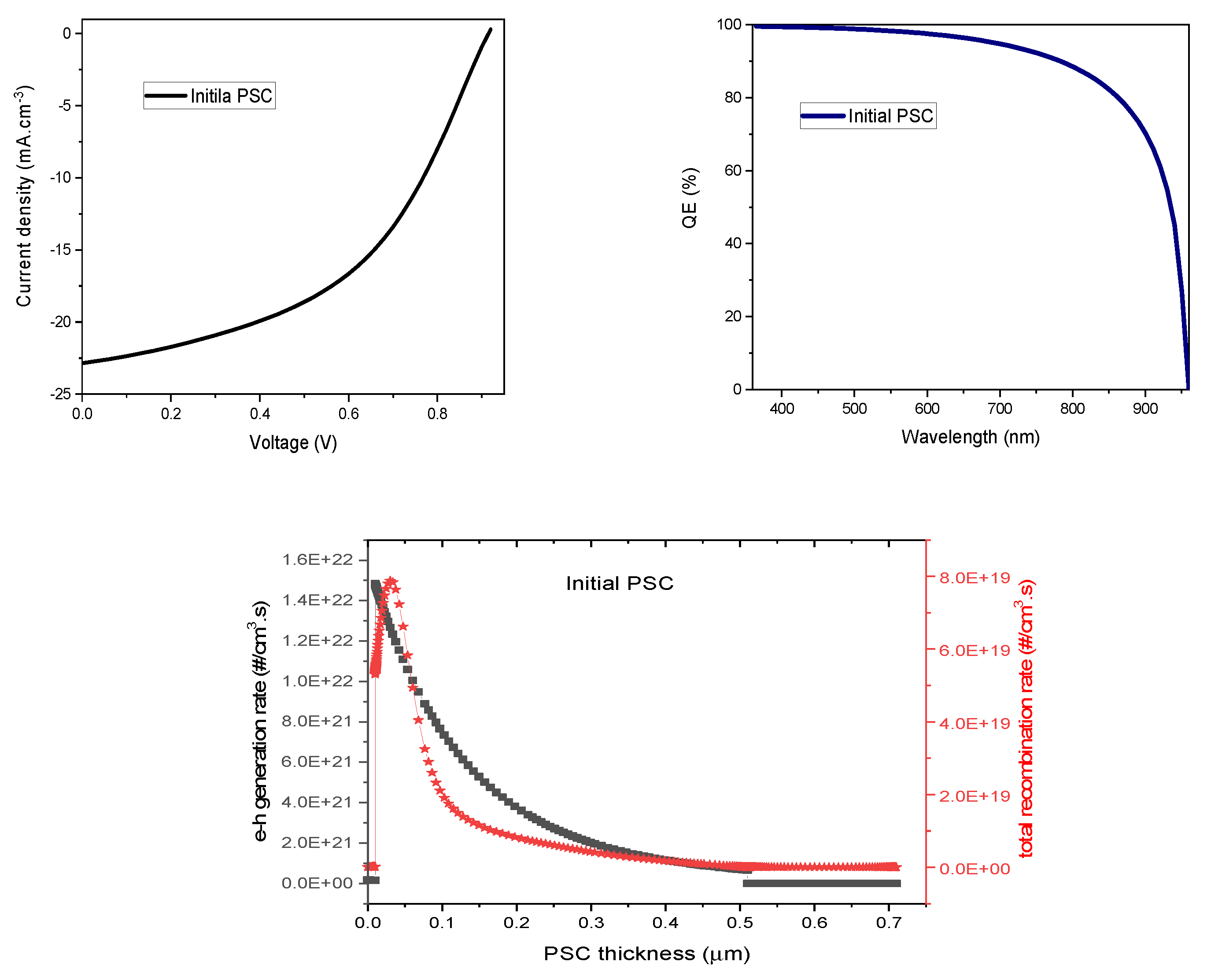
The variation of the current density with applied voltage and the spectral response (quantum efficiency) of the simulated CsSnI3 –based PSC are given as (J–V) and QE curves in Figures 2s(a) and 2(b) respectively. With the applied voltage being scanned from 0 to 1.2 V, charge carriers that are continuously generated with increasing intensity of the incident light during the simulation translated to nearly constant current density at lower voltages and at zero voltage it reaches a maximum value referred to as JSC with a magnitude of 22.859 mA.cm-2 as shown in Figure 2(a). However, as the applied voltage increases, the recombination of charge carriers in the absorber and at the n/i interface of the simulated CsSnI3 –based PSC became significant thus limiting the values of VOC to 0.915 V, as evident from Figure 2(a). The low VOC is mainly due to charge recombination at the n/i interface and in the absorber of the simulated CsSnI3 –based PSC as evident from high recombination rate in Figure 2(c). Also, the deviation of current-voltage characteristics of the simulated PSC from idealness brought about mainly by SRH recombination mechanism in the simulated device reduced the value of FF to 47.84%. Thus, the overall PCE of the simulated PSC was obtained to be 10.01%. The simulated QE curve revealed that virtually all the photons from the incident light were absorbed from 385 nm to 500 nm of the wavelength range yielding QE of approximately 87%. Beyond 500 nm, the QE gradually reduced from 87% to 50% at 821 nm and decreases sharply at about 950 nm, which corresponds to the band gap of CsSnI3 thin film as a result of the competition between charge generation rate and charge recombination rate as evident from Figure 2(c). The strong optical absorption of the simulated CsSnI3 –based PSC is attributed to the structural characteristics of CsSnI3 perovskite layer thus making it highly desirable for application in photovoltaics [59]. The obtained photovoltaic parameters for the simulated CsSnI3 –based PSC agree fairly well with recently obtained results in the literature [75,76,77,78,79]. Though, the FF, VOC and JSC are lower compared to the same CsSnI3 –based PSC with Spiro-OMETAD HTM [79], but the overall results for the simulated CsSnI3 –based PSC with CuSCN HTM using the input parameters in Table 1 are better and higher than those previously obtained for CsSnI3 –based PSC with polymer HTMs [80,81,82,83,84,85,86]. For the initial CsSnI3 –based PSC, 0.2 µm and 1017 cm-3 have been employed for the thickness and defect density of the absorber respectively and the observed diffusion lengths (0.08 µm and 0.28 µm for electrons and holes respectively) are small due to high defect density in the absorber which ultimately limits charge carrier lifetime to 0.05ns and eventually increases the recombination rate in the bulk of the initial CsSnI3 –based PSC.
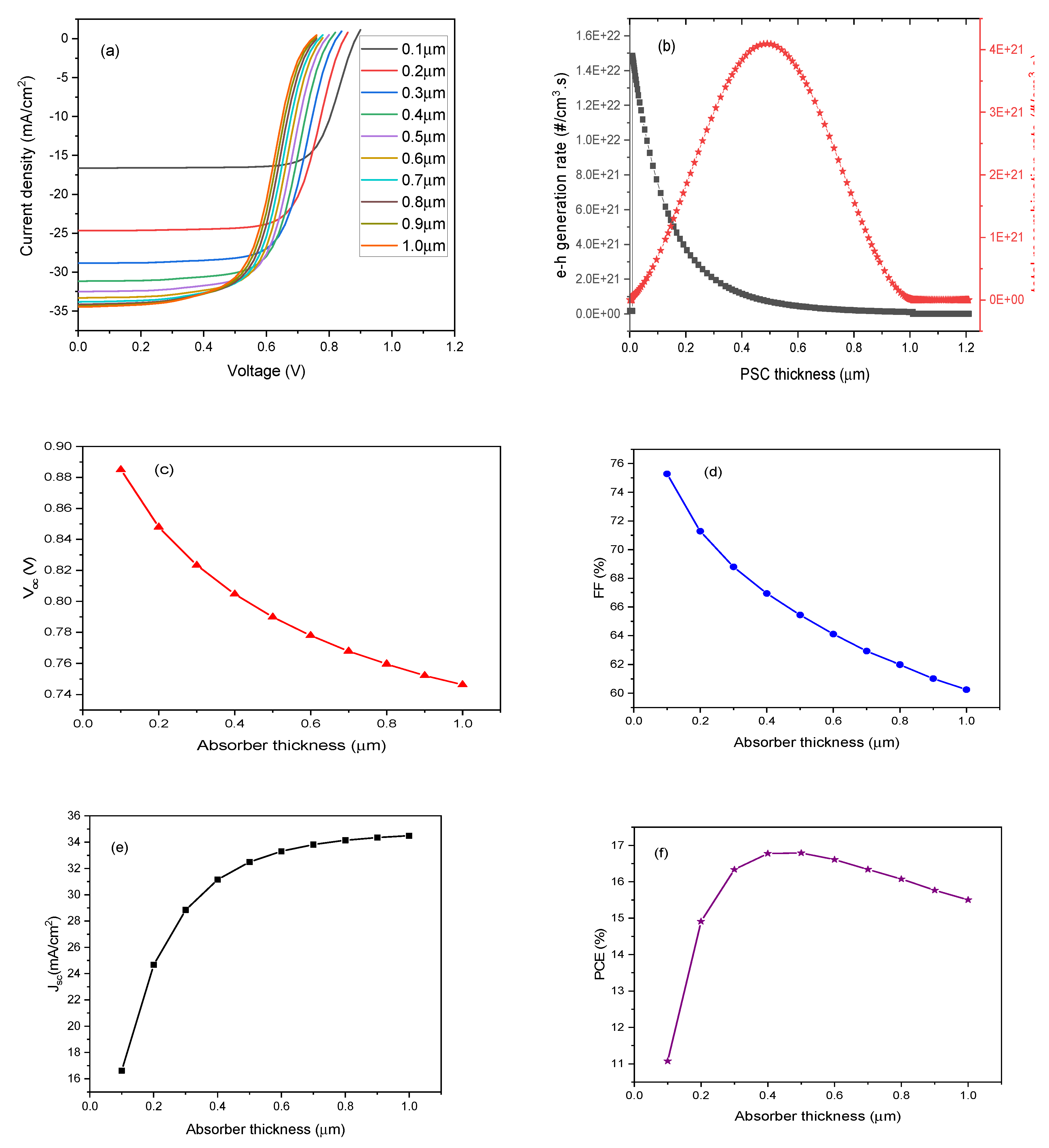
To further explore the dynamics of charge carriers in the simulated CsSnI3 –based PSC, the thickness of the absorber layer was varied from 0.1µm to 1.0 µm while maintaining the defect density at 1017 cm-3 and the results obtained are presented in Figure 3. Accordingly, as more charge carriers are generated with increase in the absorber layer thickness, the rate of recombination charge carriers also increases due to reduced mobility brought about by high defect density as depicted in Figures 3(a) and 3(b). This is evident from the reduction in the VOC and FF as the absorber thickness increases. This trend is depicted in Figure 3(c) and 3(d) respectively with the VOC reducing from a maximum value of 0.885V for absorber thickness of 0.1µm to a minimum value of 0.746V for absorber thickness of 1.0µm while the FF reduces from 75.29% to 60.25%. Nevertheless, enhancement in the values of the JSC and PCE were observed which are in agreement with previous works on CsSnI3-based PSC [78,79]. The results are presented in Figures 3(e) and 3(f) with JSC increasing from 16.62 mA.cm-2 to 34.48 mA.cm-2 for absorber thickness of 0.1µm and 1.0µm respectively while the PCE increases from 11.074% for absorber thickness of 0.1µm up to 16.793% for absorber thickness of 0.5µm followed by a gradual decrease to 15.506% for absorber thickness of 1.0µm.

3.2. Absorber Enrichment and Device Optimization

To minimize charge carrier recombination rate and enhance VOC, there is the need for compromise between the thickness of the absorber and its defect density, so that the diffusion length and the lifetime of charge carriers in the absorber are within the range required for uninterrupted transport and collection.
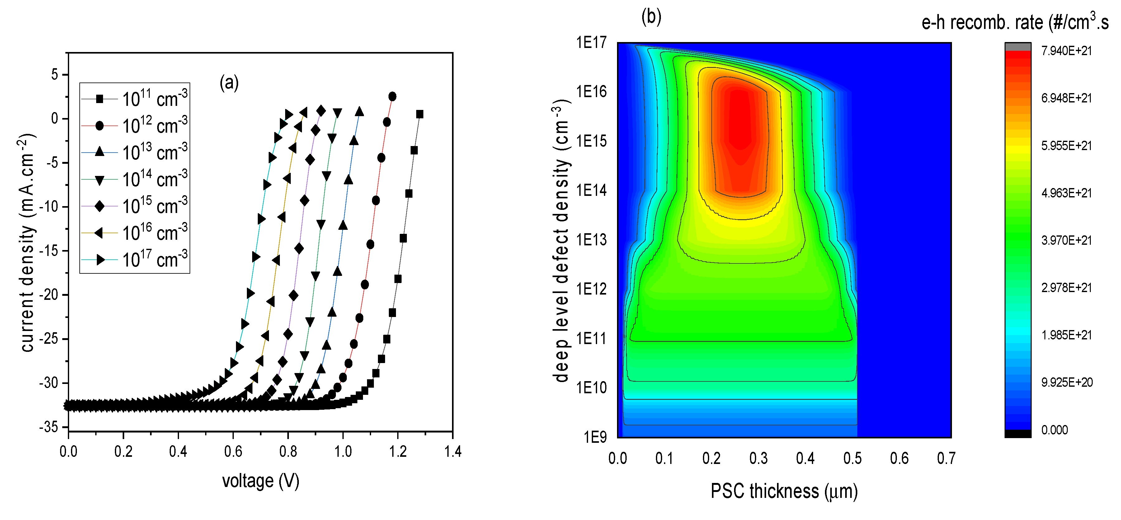
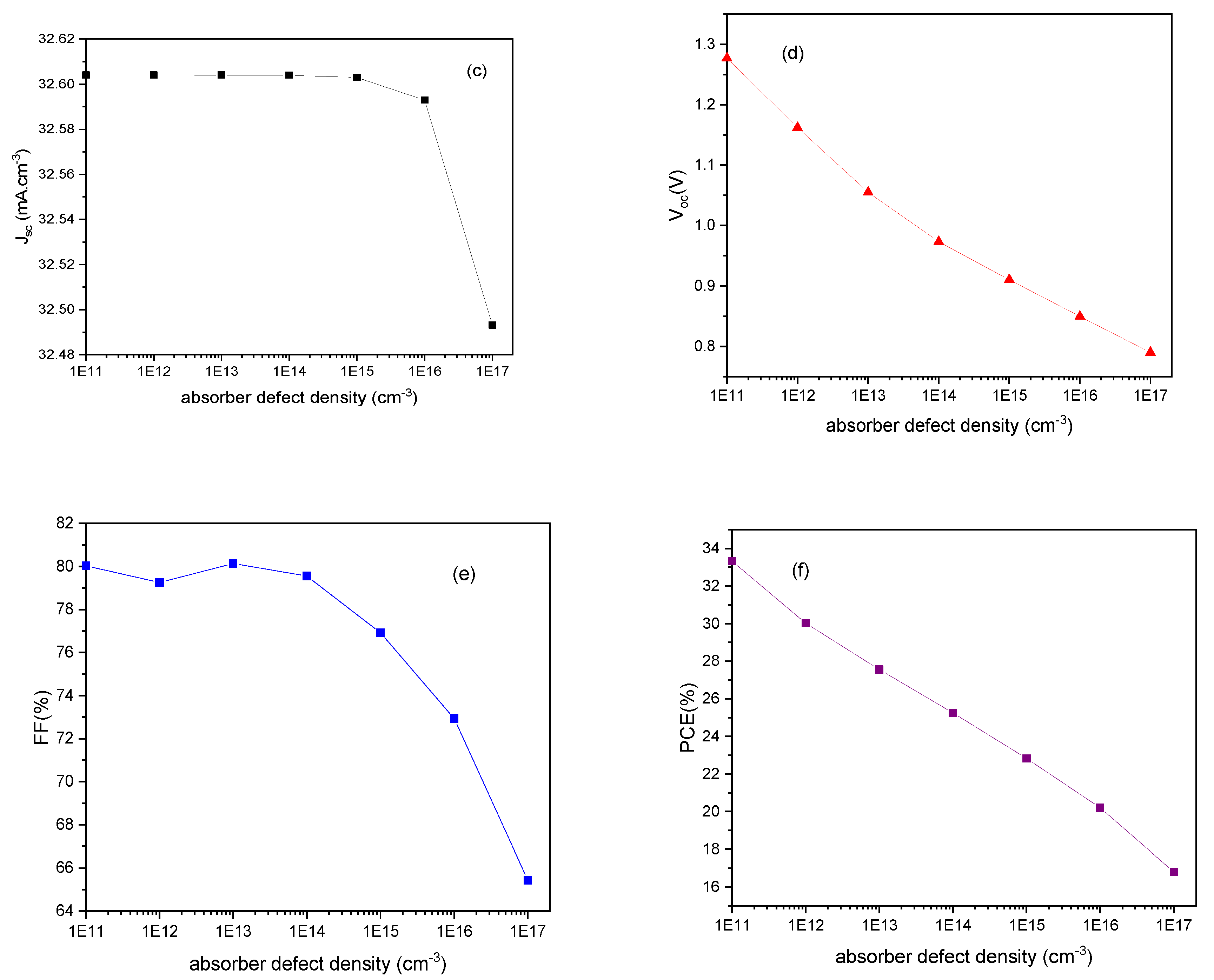
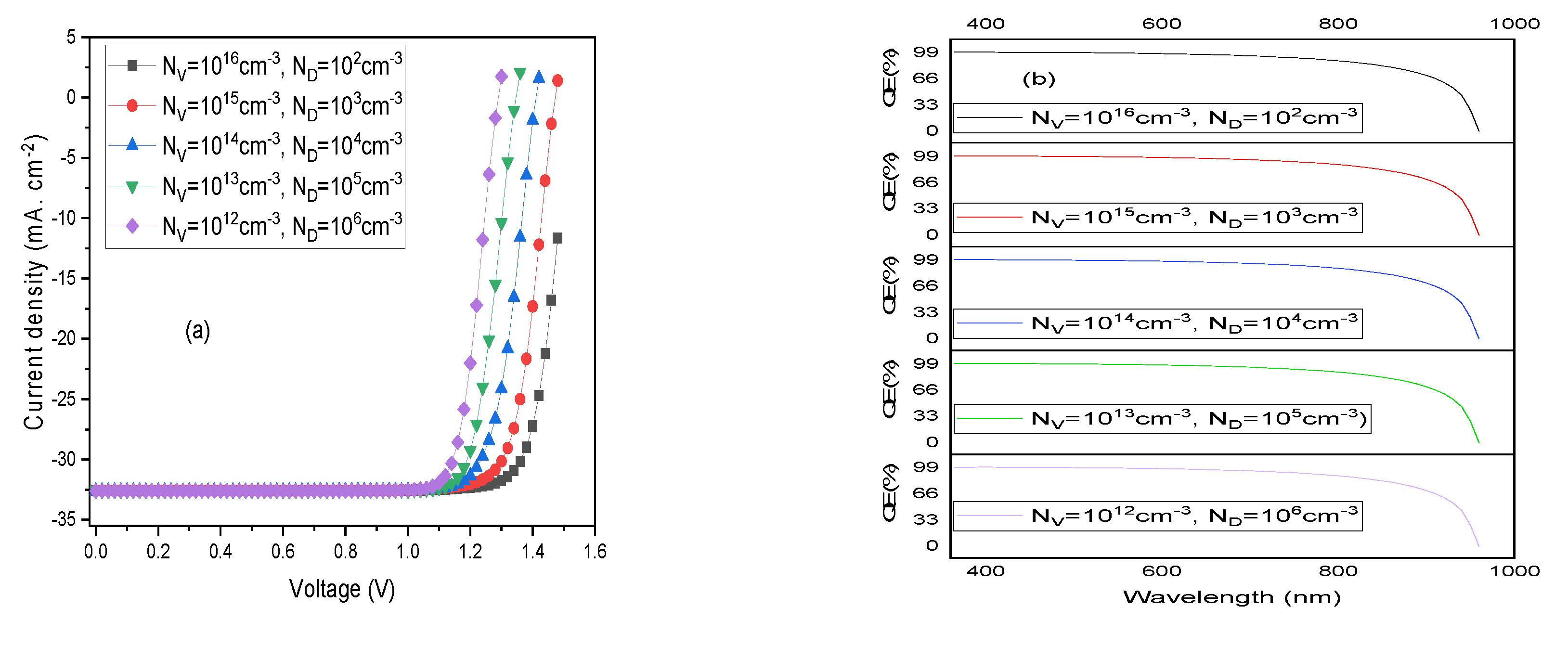
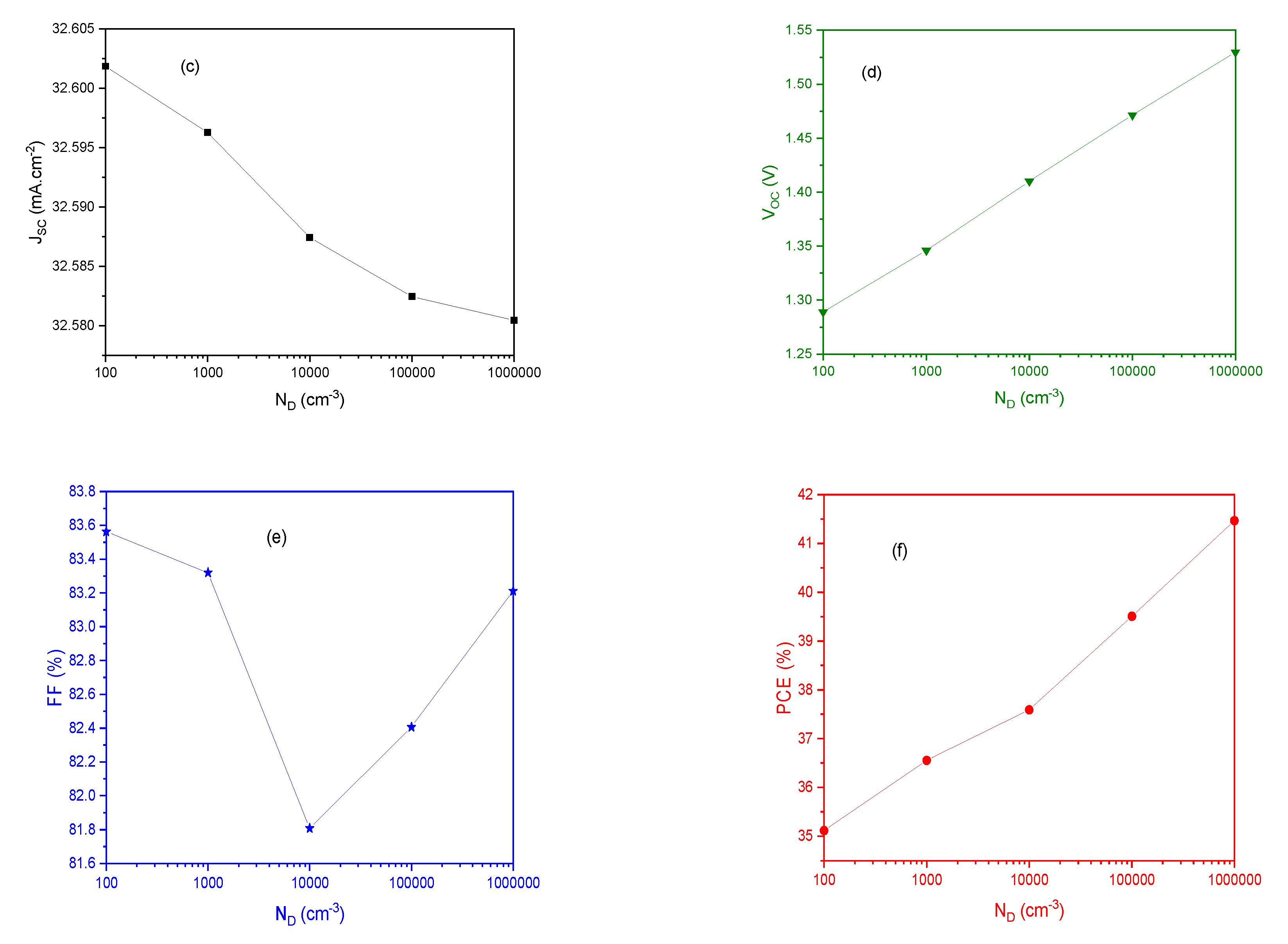
To achieve this, the defect density was tuned from 1011 cm-3 to 1017 cm-3 to gain an insight into the carrier transport dynamics with respect to the magnitude of enrichment of the absorber for real practical situations. With the results obtained from the variation of PCE with absorber thickness [Figure 3(f)], it was realized that it is pertinent to reduce the density of defects in the absorber of the simulated CsSnI3-based PSC with thickness of 0.5µm and optimum PCE. The selected absorber thickness is in agreement with previous results obtained for simulated CsSnI3–based PSCs using SCAPS software [78]. For selected thickness, the variation of the current density-voltage curves, the charge carrier recombination rate of the CsSnI3-based PSC and the photovoltaic parameters (Jsc, Voc, FF and PCE) with the absorber defect density are presented in Figure 4. The current density remained constant with an average value of 32.60 mA.cm-2 for the defect density range of interest as evident from Figure 4(c). The carrier lifetime increases from 0.05 ns to 50,000 ns as the defect density drops from 1017 cm-3 to 1011 cm-3 and this increment translates to diffusion lengths that are long enough to improve photovoltaic parameters and the PSC performance. Correspondingly, improved values were observed for VOC, FF, and PCE as the absorber defect density decreases from 1017cm-3 to 1011 cm-3. FF has an optimum value of 80.13% when the absorber defect density was reduced to 1013 cm-3 with an equivalent VOC of 1.055 V while the corresponding PCE value is 27.565%. The need to reduce the noticeable high recombination rate at the n/i interface and in the absorber as depicted in Figure 4(b) is necessary in order to improve the VOC and the PCE of the simulated CsSnI3 –based PSC beyond the Shockley-Queisser limit. Although, the initiative demonstrated above is one of the important strategies needed for the lead-free PSCs to gain entry into the global PV markets but in real practical situations, it is difficult to synthesize CsSnI3 absorber with a concentration of defect less than 1013 cm-3. This is because above room temperature, intrinsic defects are highly probable leading to the formation of significant concentration of Sn4+ vacancy (VSn) which in effect may promote recombination of holes with electrons in the stoichiometric CsSnI3. Shallow doping of lead-free Sn-based perovskites using appropriate passivation additives (e.g., SnF2, SnCl2), reducing agents (hypophosphorous acid (HPA), hydrazine) and doping ions (Br, PEA+, pn+, and TN+) have been reported in previous works to increase the formation energy of VSn and inhibit the oxidation of Sn2+ to Sn4+ [80,81,82,83,84,85,86]. In this work, it is therefore compelling to preserve the intrinsic properties and improve the stability of CsSnI3 absorber layer through enrichment using a combination of SnCl2 and Br with appropriate concentration as additive and dopant respectively. This strategy would ensure a reduced concentration of VSn and improve carrier lifetime beyond 0.05 ns as obtained for the initially simulated CsSnI3–based PSC. For a fixed concentration of Sn+4 vacancy, if cesium iodide interstitials were filled with varying concentrations of Br- and the bulk enriched with SnCl2, then the formation energy of Sn+4 vacancy would increase and the oxidation of Sn+2 to Sn+4 would be inhibited. For this work, a novel strategy was employed by fixing NA=1014 cm-3, while NV varies over a range of 1012 cm-3 to 1015 cm-3 and ND also varies over a range of 103 cm-3 to 106 cm-3. Strategically, the equilibrium hole concentration in the enriched CsSnI3 will decrease much more compared to that of the electron thereby making CsSnI3 predominantly n-type. Thus, with NC set to 1015 cm-3 and the optimum values for absorber thickness and total defect density (Nt) set to 0.5µm and 1013 cm-3 respectively, a reduced SRH recombination rate prevails leading to improved charge carrier collection efficiency and enhanced power conversion efficiency for the device. With these values, the J-V curves, QE curves and the photovoltaic parameters for the modified CsSnI3-based PSC are given in Figure 5.
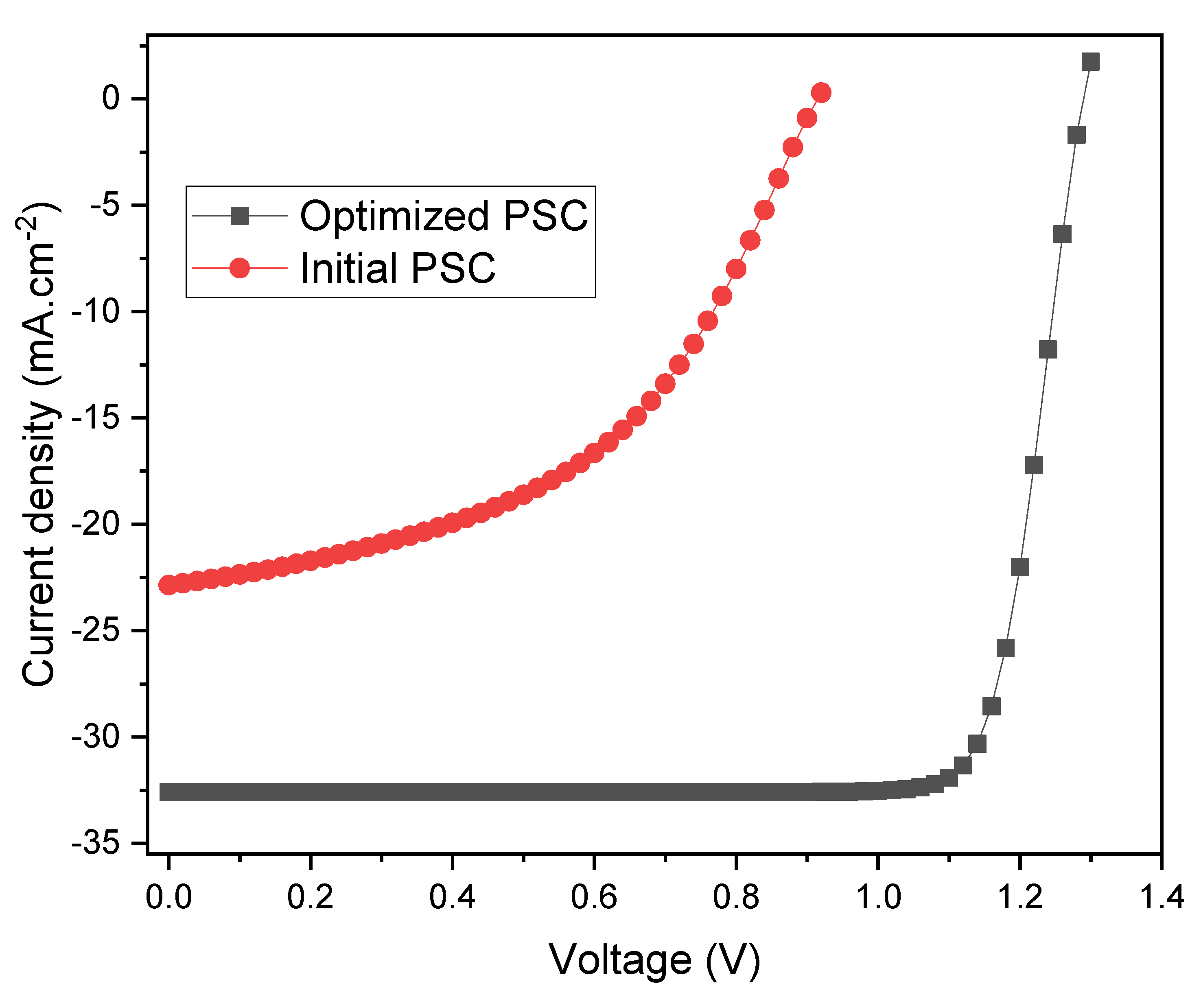
Figure 6 compares the results obtained for the initial CsSnI3-based PSC with that obtained for the optimized CsSnI3-based PSC. The overall quality and idealness of the optimized CsSnI3-based PSC are more pronounced compared to the initial CsSnI3-based PSC as evident from the high fill factor (FF), enhanced open circuit voltage (VOC) and short-circuit current density (JSC) that ultimately gave rise to improved power conversion efficiency (PCE). From the J-V curves for the optimized CsSnI3-based PSC and that for the initial CsSnI3–based PSC given in Figure 6, we observed that the improvement in VOC and JSC for the optimized CsSnI3-based PSC are approximately 29% and 30% respectively higher compared to those for the initial CsSnI3-based PSC and this confirms efficient charge carriers transport and collection with minimal recombination rate. Thus, the resulting optimized CsSnI3–based PSC performance parameters are VOC = 1.289 V, JSC = 32.60 mA.cm-2, FF = 83.56% and PCE = 35.12%.

4. Conclusions

A systematic investigation of a modeled CsSnI3-based PSC consisting of TiO2 as ETM layer, CsSnI3 as absorber layer and CuSCN as HTM layer was carried out with emphasis on enrichment of absorber layer with a view to optimizing the device performance using Solar Cell Capacitance Simulator (SCAPS-1D). For the initial CsSnI3–based PSC, 0.2 µm and 1017 cm-3 were employed for the thickness and defect density of the absorber respectively and the observed photovoltaic parameters were marred by high recombination rate of charge carriers thus limiting the values of JSC to 22.859 mA.cm-2, VOC to 0.915 V, FF to 47.84% and PCE to 10.01%. To interpret the main limitations to the initial device current-voltage characteristics, the photovoltaic parameters of the cell were analyzed by varying the absorber layer thickness. Accordingly, a reduction in the values of VOC and FF as the absorber thickness increases was evident while an enhancement in the values of the JSC and PCE was observed. The PCE value increases from 11.074% for absorber thickness of 0.1µm up to an optimum value of 16.793% for absorber thickness of 0.5µm and this was followed by a gradual decrease up to absorber thickness of 1.0µm. Subsequently, the defect density in the perovskite absorber was varied from 1011 cm-3 to 1017 cm-3 to understand the recombination rate in the absorber layer. Correspondingly, improved values were observed for VOC, FF, and PCE as the absorber defect density decreases from 1017cm-3 to 1011 cm-3 while the current density remained constant with an average value of 32.60 mA.cm-2 for the defect density range of interest. FF has optimum value of 80.13% when the absorber defect density was reduced to 1013 cm-3 with an equivalent VOC of 1.055 V while the corresponding PCE value is 27.565%. Finally, optimization of these parameters was done in conjunction with appropriate concentration of SnCl2 and Br as additive and dopant respectively to improve the PCE of the modeled CsSnI3-based PSC. This was achieved by fixing NA=1014 cm-3, while NV varies over a range of 1012 cm-3 to 1015 cm-3 and ND also varies over a range of 103 cm-3 to 106 cm-3. Thus, with NC set to 1015 cm-3 and the optimum values for absorber thickness and total defect density (Nt) set to 0.5µm and 1013 cm-3 respectively, the resulting optimized CsSnI3–based PSC performance parameters are VOC = 1.289 V, JSC = 32.60 mA.cm-2, FF = 83.56% and PCE = 35.12% which represents an improvement over the initial results and compares reasonably well with results obtained from literature [78,79,84].

References

  1. Wilson, G.M.; Al-Jassim, M.; Metzger, W.K.; Glunz, S.W.; Verlinden, P.; Xiong, G.; Mansfield, L.M.; Stanbery, B.J.; Zhu, K.; Yan, Y. The 2020 photovoltaic technologies roadmap. J. Phys. D Appl. Phys. 2020, 53, 493001. [Google Scholar] [CrossRef]
  2. Singh, B.P.; Goyal, S.K.; Kumar, P. Solar PV cell materials and technologies: Analyzing the recent developments. Mater. Today Proc. 2021, 43, 2843–2849. [Google Scholar] [CrossRef]
  3. METGroup. Renewable and Solar Energy Vs Fossil Fuels. Available online: https://group.met.com/en/mind-the-fyouture/mindthefyouture/solar-energy-vs-fossil-fuels (accessed on 25 November 2022).
  4. PV Magazine. World has Installed 1 TW of Solar Capacity. Available online: https://www.pv-magazine.com/2022/03/15/humans-have-installed-1-terawatt-of-solar-capacity/ (accessed on 25 November 2022); https://www.pv-magazine.com/2023/03/22/new-global-solar-capacity-additions-hit-191-gw-in-2022-says-irena/ (accessed on 17 May 2023).
  5. Statista. Global Cumulative Installed Solar PV Capacity 2000-2021. Available online: https://www.statista.com/statistics/280220/global-cumulative-installed-solar-pv-capacity/ (accessed on 25 November 2022).
  6. Marques Lameirinhas, R.A.; Torres, J.P.N.; de Melo Cunha, J.P. A Photovoltaic Technology Review: History, Fundamentals and Applications. Energies 2022, 15, 1823. [Google Scholar] [CrossRef]
  7. Pastuszak, J.; Wegierek, P. Photovoltaic Cell Generations and Current Research Directions for Their Development. Materials 2022, 15, 5542. [Google Scholar] [CrossRef] [PubMed]
  8. Xiong, Y.; Liu, Y.; Lan, K.; Mei, A.; Sheng, Y.; Zhao, D.; Han, H. Fully printable hole-conductor-free mesoscopic perovskite solar cells based on mesoporous anatase single crystals. New J. Chem. 2018, 42, 2669. [Google Scholar] [CrossRef]
  9. Zhang, P.; Wu, J.; Zhang, T.; Wang, Y.; Liu, D.; Chen, H.; Ji, L.; Liu, C.; Ahmad, W.; Chen, Z. D.; Li, S. Perovskite Solar Cells with ZnO Electron-Transporting Materials. Adv. Mater. 2018, 30, 1703737. [Google Scholar] [CrossRef]
  10. Jiang, T.; Fu, W. Improved performance and stability of perovskite solar cells with bilayer electron-transporting layers. RSC Adv. 2018, 8, 5897. [Google Scholar] [CrossRef]
  11. Chen, S.; Yang, S.; Sun, H.; Zhang, L.; Peng, J.; Liang, Z.; Wang, Z. S. Enhanced interfacial electron transfer of inverted perovskite solar cells by introduction of CoSe into the electron-transporting-layer. J. Power Sources 2017, 353, 123. [Google Scholar] [CrossRef]
  12. Jena, A. K.; Numata, Y.; Ikegami, M.; Miyasaka, T. Role of spiro-OMeTAD in performance deterioration of perovskite solar cells at high temperature and reuse of the perovskite films to avoid Pb-waste. J. Mater. Chem. A 2018, 6, 2219–2230. [Google Scholar] [CrossRef]
  13. Ng, C. H.; Ripolles, T. S.; Hamada, K.; Teo, S. H.; Lim, H. N.; Bisquert, J.; Hayase, S. Tunable Open Circuit Voltage by Engineering Inorganic Cesium Lead Bromide/Iodide Perovskite Solar Cells. Sci. Rep. 2018, 8, 2482. [Google Scholar] [CrossRef]
  14. Neophytou, M.; Griffiths, J.; Fraser, J.; Kirkus, M.; Chen, H.; Nielsen, C. B.; McCulloch, I. High mobility, hole transport materials for highly efficient PEDOT:PSS replacement in inverted perovskite solar cells. J. Mater. Chem. C 2017, 5, 4940–4945. [Google Scholar] [CrossRef]
  15. NREL. Best Research-Cell Efficiency Chart. Available online: https://www.nrel.gov/pv/cell-effienciency.html (accessed on 24 November 2022).
  16. Sharma, P.; Goyal, P. Evolution of PV technology from conventional to nano-materials. Mater. Today Proc. 2020, 28, 1593–1597. [Google Scholar] [CrossRef]
  17. Baena, J.P.C.; Abate, A.; Saliba, M.; Tress,W.; Jacobsson, J.; Grätzel, M.; Hagfeldt, A. The rapid evolution of highly efficient perovskite solar cells. Energy Environ. Sci. 2017, 10, 710–727. [CrossRef]
  18. Haider, S. Z.; Anwar, H.; Wang, M. Theoretical Device Engineering for High-Performance Perovskite Solar Cells Using CuSCN as Hole Transport Material Boost the Efficiency Above 25%. Phys. Status Solidi A 2019, 216, 1900102. [Google Scholar] [CrossRef]
  19. Kima, B. and Seok, S.I. Molecular aspects of organic cations affecting the humidity stability of perovskites. Energy Environ. Sci. 2020, 13, 805–820. [CrossRef]
  20. Neophytou, M.; Griffiths, J.; Fraser, J.; Kirkus, M.; Chen, H.; Nielsen, C. B.; McCulloch, I. High mobility, hole transport materials for highly efficient PEDOT:PSS replacement in inverted perovskite solar cells. J. Mater. Chem. C 2017, 5, 4940–4945. [Google Scholar] [CrossRef]
  21. Chen, W. Y.; Deng, L. L.; Dai, S. M.; Wang, X.; Tian, C. B.; Zhan, X. X.; Xie, S. Y.; Huang, R. B.; Zheng, L. S. Low-cost solution-processed copper iodide as an alternative to PEDOT:PSS hole transport layer for efficient and stable inverted planar heterojunction perovskite solar cells. J. Mater. Chem. A 2015, 3, 19353–19359. [Google Scholar] [CrossRef]
  22. Li, X.; Yang, J.; Jiang, Q.; Chu, W.; Zhang, D.; Zhou, Z.; Xin, J. Synergistic Effect to High-Performance Perovskite Solar Cells with Reduced Hysteresis and Improved Stability by the Introduction of Na-Treated TiO2 and Spraying-Deposited CuI as Transport Layers ACS Appl. Mater. Interfaces 2017, 9, 41354. [Google Scholar] [CrossRef]
  23. Kumara, G.R.R.A.; Konno, A.; Senadeera, G.K.R.; Jayaweera, P.V.V.; De Silva, D.B.R.A.; Tennakone, K. Dye-Sensitized solar cell with the hole collector p-CuSCN deposited from a solution in n-Propyl sulphide. Sol. Energy Mater. Sol. Cells 2001, 69, 195–199. [Google Scholar] [CrossRef]
  24. Li, M.-H.; Yum, J.-H.; Moon, S.-J.; Chen, P. Inorganic p-Type Semiconductors: Their Applications and Progress in Dye-Sensitized Solar Cells and Perovskite Solar Cells. Energies 2016, 9, 331. [Google Scholar] [CrossRef]
  25. Hehl, R.; Thiele, G. Synthesis and Crystal Structure of Me3NHCu2(SCN)3, Me2C=NMe2Cu2(SCN)3, and Me2C=NMe2Ag2(SCN)3. Three-dimensional Networks of Thiocyanatometallates(I). Zeitschrift für Anorganische und Allgemeine Chemie 2000, 626, 2167–2172. [Google Scholar] [CrossRef]
  26. Mahrov, B.; Hagfeldt, A.; Lenzmann, F.; Boschloo, G. Comparison of charge accumulation and transport in nanostructured dye-Sensitized solar cells with electrolyte or CuSCN as hole conductor. Sol. Energy Mater. Sol. Cells 2005, 88, 351–362. [Google Scholar] [CrossRef]
  27. Pattanasattayavong, P.; Ndjawa, G. O. N.; Zhao, K.; Chou, K. W.; Yaacobi-Gross, N.; O’Regan, B. C.; Amassian, A.; Anthopoulos, T. D. Electric field-induced hole transport in copper(i) thiocyanate (CuSCN) thin-films processed from solution at room temperature. Chem. Commun. 2013, 49, 4154–4156. [Google Scholar] [CrossRef] [PubMed]
  28. Yang, I. S.; Sohn, M. R.; Do Sung, S.; Kim, Y. J.; Yoo, Y. J.; Kim, J.; Lee, W. I. Formation of pristine CuSCN layer by spray deposition method for efficient perovskite solar cell with extended stability. Nano Energy 2017, 32, 414. [Google Scholar] [CrossRef]
  29. Qin, P.; Tanaka, S.; Ito, S.; Tetreault, N.; Manabe, K.; Nishino, H.; Nazeeruddin, M. K.; Gratzel, M. Inorganic hole conductor-based lead halide perovskite solar cells with 12.4% conversion efficiency. Nat. Commun. 2014, 5, 1. [Google Scholar] [CrossRef]
  30. Jung, M.; Kim, Y. C.; Jeon, N. J.; Yang, W. S.; Seo, J.; Noh, J. H.; Seok, S. I. Thermal Stability of CuSCN Hole Conductor-Based Perovskite Solar Cells. ChemSusChem 2016, 9, 2592. [Google Scholar] [CrossRef]
  31. Anttu, N. Shockley–Queisser Detailed Balance Efficiency Limit for Nanowire Solar Cells. ACS Photonics 2015, 2, 446. [Google Scholar] [CrossRef]
  32. Sha, W. E. I.; Ren, X.; Chen, L.; Choy, W. C. H. The efficiency limit of CH3NH3PbI3 perovskite solar cells. Appl. Phys. Lett. 2015, 106, 1. [Google Scholar] [CrossRef]
  33. Mostefaoui, M.; Mazari, H.; Khelifi, S.; Bouraiou, A.; Dabou, R. Simulation of High Efficiency CIGS Solar Cells with SCAPS-1D Software. Energy Procedia 2015, 74, 736. [Google Scholar] [CrossRef]
  34. Toshniwal, A.; Jariwala, A.; Kheraj, V.; Opanasyuk, A. S.; Panchal, C. J. Numerical Simulation of Tin Based Perovskite Solar Cell: Effects of Absorber Parameters and Hole Transport Materials. jnep 2017, 9, 03038. [Google Scholar] [CrossRef]
  35. Haider, S. Z.; Anwar, H.; Wang, M. A comparative study of interface engineering with different hole transport materials for high-performance perovskite solar cells. Semicond. Sci. Technol. 2018, 33, 35001. [Google Scholar] [CrossRef]
  36. Anwar, F.; Mahbub, R.; Satter, S. S.; Ullah, S. M. Effect of Different HTM Layers and Electrical Parameters on ZnO Nanorod-Based Lead-Free Perovskite Solar Cell for High-Efficiency Performance. Int. J. Photoenergy. 2017, 2017, 1–9. [Google Scholar] [CrossRef]
  37. Babayigit, A.; Duy Thanh, D.; Ethirajan, A.; Manca, J.; Muller, M.; Boyen, H.G.; Conings, B. Assessing the toxicity of Pb- and Sn-based perovskite solar cells in model organism Danio rerio. Sci. Rep. 2016, 6, 18721. [Google Scholar] [CrossRef]
  38. Li, J.; Cao, H. L.; Jiao, W. B.; Wang, Q.; Wei, M.; Cantone, I.; Lü, J.; Abate, A. Biological impact of lead from halide perovskites reveals the risk of introducing a safe threshold. Nat Commun. 2020, 11, 1–310. [Google Scholar] [CrossRef]
  39. Islam, M. T.; Jani, M. R.; Al Amin, S. M.; Sami, M. S. U.; Shorowordi, K. M.; Hossain, M. I.; Devgun, M.; Chowdhury, A. S.; Bernajee, S.; Ahmed, S. Numerical simulation studies of a fully inorganic Cs2AgBiBr6 perovskite solar device. Optical Materials 2020, 105, 109957. [Google Scholar] [CrossRef]
  40. Du, K. Meng, W., Wang, X., Yan, Y. & Mitzi, D. B. Bandgap Engineering of Lead-Free Double Perovskite Cs2AgBiBr6 through Trivalent Metal Alloying. Angew. Chem. Int. Ed. 2017, 56, 8158–8162.
  41. Ju, M.-G.; Chen, M.; Zhou, Y.; Garces, H. F.; Dai, J.; Ma, L.; Padture, N. P.; Zeng, X. C. Earth-Abundant Nontoxic Titanium(IV)-based Vacancy-Ordered Double Perovskite Halides with Tunable 1.0 to 1.8 eV Bandgaps for Photovoltaic Applications. ACS Energy Lett. 2018, 3, 297–304. [Google Scholar] [CrossRef]
  42. Wang, N.; Zhou, Y.; Ju, M-G.; Garces, H. F.; Ding, T.; Pang, S.; Zeng, X. C.; Padture, N. P.; Sun, X. W. Heterojunction-Depleted Lead-Free Perovskite Solar Cells with Coarse-Grained B-γ-CsSnI3 Thin Films. Adv. Energy Mater. 2016, 01, 130.
  43. Canil, L.; Salunke, J.; Wang, Q.; Liu, M.; Köbler, H.; Flatken, M.; Gregori, L.; Meggiolaro, D.; Ricciarelli, D.; De Angelis, F.; Stolterfoht, M.; Neher, D.; Priimagi, A.; Vivo, P.; Abate, A. Halogen-Bonded Hole-Transport Material Suppresses Charge Recombination and Enhances Stability of Perovskite Solar Cells. Adv. Energy Mater. 2021, 01, 553.
  44. Chen, M.; Ju, M-G.; Garces, H. F.; Carl, A. D.; Ono, L. K.; Hawash, Z.; Zhang, Y.; Shen, T.; Qi, Y.; Grimm, R. L.; Pacifici, D.; Zeng, X. C.; Zhou, Y.; Padture, N. P. Highly stable and efficient all-inorganic lead-free perovskite solar cells with native-oxide passivation. Nature Commun. 2019, 10, 16. [Google Scholar] [CrossRef]
  45. Shao, S.; Liu, J.; Portale, G.; Fang, H-H.; Blake, G. R.; Brink, G. H.; L. Jan Anton Koster, J. A.; Loi, M. A. Highly Reproducible Sn-Based Hybrid Perovskite Solar Cells with 9% Efficiency. Adv. Energy Mater. 2018, 8, 1702019. [Google Scholar] [CrossRef]
  46. Targhi, F. F.; Jalili, Y. S.; Kanjouri, F. MAPbI3 and FAPbI3 perovskites as solar cells: Case study on structural, electrical and optical properties. Results in Physics 2018, 10, 616–627. [Google Scholar] [CrossRef]
  47. Marshall, K. P.; Walker, M.; Walton, R. I.; Hatton, R. A. Enhanced stability and efficiency in hole-transport-layer-free CsSnI3 perovskite photovoltaics. Nature Energy 2016, 1, 16178. [Google Scholar] [CrossRef]
  48. Chung, I.; Lee, B.; He, J.; Chang, R.P.H.; Kanatzidis, M.G. All-Solid-State Dye-Sensitized solar cells with high efficiency. Nature 2012, 485, 486–489. [Google Scholar] [CrossRef]
  49. Wu, J.; Lan, Z.; Lin, J.; Huang, M.; Huang, Y.; Fan, L.; Luo, G. Electrolytes in Dye-Sensitized Solar Cells. Chem. Rev. 2015, 115, 2136–2173. [Google Scholar] [CrossRef]
  50. Bach, U.; Daeneke, T. A Solid Advancement for Dye-Sensitized Solar Cells. Angew. Chem. Int. Ed. 2012, 51, 10451–10452. [Google Scholar] [CrossRef]
  51. Mallouk, T.E. Applied chemistry: Molecules meet materials. Nature 2012, 485, 450–451. [Google Scholar] [CrossRef]
  52. Chen, Z.; Wang, J.J.; Ren, Y.; Yu, C.; Shum, K. Schottky solar cells based on CsSnI3 thin-films. Appl. Phys. Lett. 2012, 101, 093901. [Google Scholar] [CrossRef]
  53. Shum, K.; Chen, Z.; Qureshi, J.; Yu, C.; Wang, J.J.; Pfenninger, W.; Vockic, N.; Midgley, J.; Kenney, J.T. Synthesis and characterization of CsSnI3 thin films. Appl. Phys. Lett. 2010, 96, 221903. [Google Scholar] [CrossRef]
  54. Yu, C.; Chen, Z.J.; Wang, J.; Pfenninger, W.; Vockic, N.; Kenney, J.T.; Shum, K. Temperature dependence of the band gap of perovskite semiconductor compound CsSnI3. J. Appl. Phys. 2011, 110, 063526. [Google Scholar] [CrossRef]
  55. Chen, Z.; Yu, C.; Shum, K.; Wang, J.J.; Pfenninger, W.; Vockic, N.; Midgley, J.; Kenney, J.T. Photoluminescence study of polycrystalline CsSnI3 thin films: Determination of exciton binding energy. J. Lumin. 2012, 132, 345–349. [Google Scholar] [CrossRef]
  56. Yamada, K.; Funabiki, S.; Horimoto, H.; Matsui, T.; Okuda, T.; Ichiba, S. Structural Phase Transitions of the Polymorphs of CsSnI3 by Means of Rietveld Analysis of the X-Ray Di_raction. Chem. Lett. 1991, 20, 801–804. [Google Scholar] [CrossRef]
  57. Chung, I.; Song, J.-H.; Im, J.; Androulakis, J.; Malliakas, C.D.; Li, H.; Freeman, A.J.; Kenney, J.T.; Kanatzidis, M.G. CsSnI3: Semiconductor or Metal? High Electrical Conductivity and Strong Near-Infrared Photoluminescence from a Single Material. High Hole Mobility and Phase-Transitions. J. Am. Chem. Soc. 2012, 134, 8579–8587. [Google Scholar] [CrossRef] [PubMed]
  58. Zhou, Y.; Garces, H.F.; Senturk, B.S.; Ortiz, A.L.; Padture, N.P. Room temperature “one-Pot” solution synthesis of nanoscale CsSnI3 orthorhombic perovskite thin films and particles. Mater. Lett. 2013, 110, 127–129. [Google Scholar] [CrossRef]
  59. Chung, I.; Lee, B. H.; He, J.; Chang, R.; Kanatzidis, M.G. All-solid-state dye-sensitized solar cells with high efficiency. Nature 2012, 485, 486–9. [Google Scholar] [CrossRef] [PubMed]
  60. Sze, S.M.; Ng, K. Physics of Semiconductor Devices; John Wiley & Sons:, 2006. [Google Scholar]
  61. Kumar, M. H.; Dharani, S.; Leong, W. L. , Boix, P. P.; Prabhakar, R. R.; Baikie, T.; Shi, C.; Ding, H.; Ramesh, R.; Asta, M.; Graetzel M.; Mhaisalkar, S. G.; Mathews, N. Lead-free halide perovskite solar cells with high photocurrents realized through vacancy modulation. Adv. Mater. 2014, 26, 7122–7127. [CrossRef] [PubMed]
  62. Wu, B.; Zhou, Y.; Xing, G.; Xu, Q.; Garces, H. F.; Solanki, A.; Goh, T. W.; Padture, N. P.; Sum, T. C. Long minority-carrier diffusion length and low surface-recombination velocity in inorganic lead-free CsSnI3 perovskite crystal for solar cells. Adv. Funct. Mater. 2017, 27, 1604818. [Google Scholar] [CrossRef]
  63. Pfeifer, V.; Erhart, P.; Li, S.; Rachut, K.; Morasch, J.; Brötz, J.; Reckers, P.; Mayer, T.; Rühle, S.; Zaban, A.; Mora Sero, I.; Bisquert, J.; Jaegermann, W.; Klein, A. Klein, Energy Band Alignment between Anatase and Rutile TiO2. J Phys. Chem. Lett. 2013, 4, 4182–4187. [Google Scholar] [CrossRef]
  64. Wijeyasinghe, N.; Regoutz, A.; Eisner, F.; Du, T.; Tsetseris, L.; Lin, Y.-H.; Faber, H.; Pattanasattayavong, P.; Li, J.; Yan, F.; McLachlan, M.A.; Payne, D.J.; Heeney, M.; Anthopoulos, T.D. Copper(I) Thiocyanate (CuSCN) Hole-Transport Layers Processed from Aqueous Precursor Solutions and Their Application in Thin-Film Transistors and Highly Efficient Organic and Organometal Halide Perovskite Solar Cells. Adv. Funct. Mater. 2017, 27, 35. [Google Scholar] [CrossRef]
  65. Babaei, F. H.; Sheini, N. A.; . Lajvardi, M. M. Oxygen adsorption at noble metal/TiO2 junctions. IOP Conference Series: Materials Science and Engineering 2016, 108, 012030. [Google Scholar] [CrossRef]
  66. Grover, S.; Moddel, G. Metal Single-Insulator and Multi-Insulator Diodes for Rectenna Solar Cells; Springer, 2013; pp. 89–109. [Google Scholar]
  67. Lajvardi, M. M.; Jahangiri, M. Ni/TiO2 ultraviolet detector IOP Conf. Ser. Mater. Sci. Eng. 2016, 108, 012031. [Google Scholar]
  68. Gavrilov, S. A.; Zheleznyakova, A. V.; Dronov, A. A.; Dittrich, T. Efficiency Enhancement of Eta-cells Fabricated by SILAR Deposition. Phy. Chem. Appl. Nanostructures 2009, 577–580. [Google Scholar]
  69. Boschloo, G.; Edvinsson, T.; Hagfeldt, A. Nanostructured Materials for Solar Energy Conversion, 1st ed.; Elsevier: Amsterdam, 2006. [Google Scholar]
  70. Jaffe, J. E.; Kaspar, T. C.; Droubay, T. C.; Varga, T.; Bowden, M. E.; Exarhos, G. J. Electronic and Defect Structures of CuSCN. J. Phys. Chem. C 2010, 114, 9111–9117. [Google Scholar] [CrossRef]
  71. Zhao, T.; Shi, W.; Xi, J.; Wang, D.; Shuai, Z. Intrinsic and Extrinsic Charge Transport in CH3NH3PbI3 Perovskites Predicted from First-Principles. Sci. Rep. 2016, 7, 1. [Google Scholar]
  72. Hossain, M. I.; Alharbi, F. H.; Tabet, N. Copper oxide as inorganic hole transport material for lead halide perovskite based solar cells. Sol. Energy 2015, 120, 370. [Google Scholar] [CrossRef]
  73. Zhang, Q.; Dandeneau, C. S.; Zhou, X.; Cao, G. ZnO nanostructures for dye-sensitized solar cells Adv. Mater. 2009, 21, 4087. [Google Scholar]
  74. Pattanasattayavong, P.; Promarak, V.; Anthopoulos, T. D. Electronic Properties of Copper(I) Thiocyanate (CuSCN). Adv. Electron. Mater. 2017, 3, 1600378. [Google Scholar] [CrossRef]
  75. Wang, Y.; Tu, J.; Li, T.; Tao, C.; Deng, X.; Li, Z. Convenient preparation of CsSnI3 quantum dots, excellent stability, and the highest performance of lead-free inorganic perovskite solar cells so far. J. Mater. Chem. A 2019, 7, 7683–7690. [Google Scholar] [CrossRef]
  76. Ma, S.; Gu, X.; Kyaw, A. K.; Wang, D. H.; Priya, S.; Ye, T. Fully Inorganic CsSnI3-based solar cells with>6% efficiency and enhanced stability enabled by mixed electron transport layer. ACS Appl. Mater. Interfaces 2021, 13, 1345–1352. [Google Scholar] [CrossRef]
  77. Li, B.; Di, H.; Chang, B.; Yin, R.; Fu, L.; Zhang, Y.; Yin, L. Efficient passivation strategy on Sn related defects for high performance all-inorganic CsSnI3 perovskite solar cells. Adv. Funct. Mater. 2021, 31, 2007447. [Google Scholar] [CrossRef]
  78. Ye, T.; Wang, X.; Wang, K.; Ma, S.; Yang, D.; Hou, Y.; Yoon, J.; Wang, K.; Priya, S. Localized electron density engineering for stabilized B-γ CsSnI3-based perovskite solar cells with efficiencies >10%. ACS Energy Lett. 2021, 6, 1480–1489. [Google Scholar] [CrossRef]
  79. Shuo, L., Baoping Z., Tie-Yu L., Jin-Cheng Z., Huaqing P., Huanting C., Chuanjin L., Xirong L., Jinrong Z. Inorganic Lead-Free B-γ-CsSnI3 Perovskite Solar Cells Using Diverse Electron-Transporting Materials: A Simulation Study. ACS Omega 2021, 6, 26689–26698. [CrossRef] [PubMed]
  80. Song, T-B.; Yokoyama, T.; Stoumpos, C. C.; Logsdon, J.; Cao, D. H.; Wasielewski, M. R.; Aramaki, S.; Kanatzidis, M. G. Importance of reducing vapor atmosphere in the fabrication of Tin-based perovskite solar cells. J. Am. Chem. Soc. 2017, 139, 836–842. [Google Scholar] [CrossRef] [PubMed]
  81. Song, T-B.; Yokoyama, T.; Aramaki, S.; Kanatzidis, M.G. Performance enhancement of lead-free tin-based perovskite solar cells with reducing atmosphere-assisted dispersible additive. ACS Energy Lett. 2017, 2, 897–903. [Google Scholar] [CrossRef]
  82. Zhu, P.; Chen, C.; Gu, S.; Lin, R.; Zhu, J. CsSnI3 Solar Cells via an Evaporation- Assisted Solution Method. Sol. RRL. 2018, 2, 1700224. [Google Scholar] [CrossRef]
  83. Heo, J.H.; Kim, J.; Kim, H.; Moon, S.H.; Im, S.H.; Hong, K.H. Roles of SnX2 (X=F, Cl, Br) additives in tin-based halide perovskites toward highly efficient and stable lead-free perovskite solar cells. J. Phys. Chem. Lett. 2018, 9, 6024–6031. [Google Scholar] [CrossRef]
  84. Ban, H.; Zhang, T.; Gong, X.; Sun, Q.; Zhang, X.-L.; Pootrakulchote, N.; Shen, Y.; Wang, M. Fully inorganic CsSnI3 mesoporous perovskite solar cells with high efficiency and stability via coadditive engineering, Sol. RRL. 2021, 5, 2100069. [Google Scholar]
  85. Ye, T.; Wang, K.; Hou, Y.; Yang, D.; Smith, N.; Magill, B.; Yoon, J.; Mudiyanselage, R. H. H.; Khodaparast, G. A.; Wang, K.; Priya, S. Ambient-air-stable lead-free CsSnI3 Solar cells with greater than 7.5% efficiency. J. Am. Chem. Soc. 2021, 143, 4319–4328. [Google Scholar] [CrossRef]
  86. Ban, H.; Nakajima, T.; Liu, Z.; Yu, H.; Sun, Q.; Dai, L.; Shen, Y.; Zhang, X-L; Zhu, J.; Chen, P.; Mingkui Wang, M. Over 8% efficient CsSnI3-based mesoporous perovskite solar cells enabled by two-step thermal annealing and surface cationic coordination dual treatment. J. Mater. Chem. 2022, 10, 3642–3649. [Google Scholar] [CrossRef]
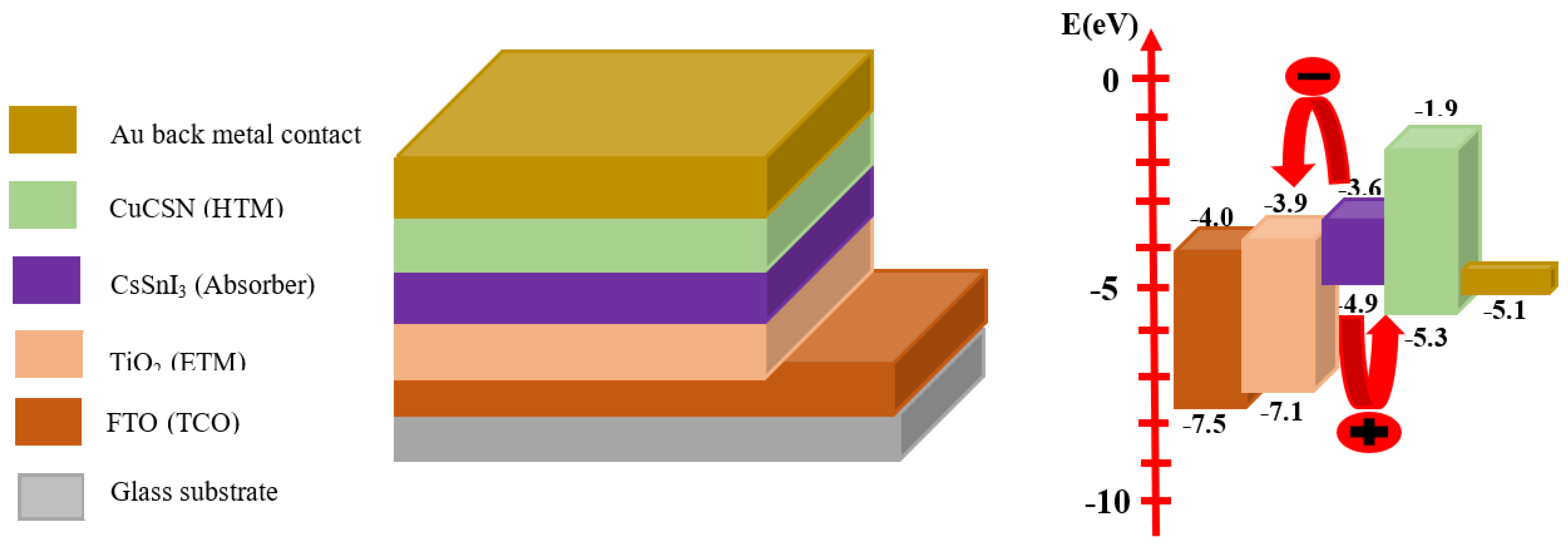
Figure 1. Schematic of the PSC structure (a) Device architecture and (b) Band diagram of the active layers.
Preprints 80961 g001
Figure 2. Performance characteristics of the simulated initial PSC (a) current density-voltage curve (b) quantum efficiency curve and (c) e-h generation and recombination rates.
Preprints 80961 g002
Figure 3. Variation of Performance parameters with absorber thickness (a) current density-voltage characteristics, (b) e-h generation and recombination rates and [(c)-(f)] photovoltaic parameters.
Preprints 80961 g003
Figure 4. Variation of Performance parameters with absorber defect density (a) current density-voltage characteristics, (b) e-h recombination rates with PSC thickness and [(c)-(f)] photovoltaic parameters.
Preprints 80961 g004aPreprints 80961 g004b
Figure 5. Variation of performance parameters for the modified CsSnI3-based PSC with donor concentration (a) current density-voltage curves (b) Quantum efficiency curves (c) short-circuit current density (d) open-circuit voltage (e) Fill factor and (f) Power conversion efficiency.
Preprints 80961 g005aPreprints 80961 g005b
Figure 6. Current Density-Voltage Characteristics for the optimized and initial CsSnI3-based PSC.
Preprints 80961 g006
Table 1. Parameters set for the simulation of Perovskite solar cell.
Parameters FTO TiO2 CsSnI3 CuSCN
Thickness (µm)
Band-gap energy Eg (eV)
Electron affinity χ (eV)
Relative Permittivity εr
Effective conduction band density Nc (cm-3)
Effective valence band density Nv (cm-3)
Electron mobility µn (cm2V-1 s-1)
Hole mobility µp (cm2V-1 s-1)
Donor concentration ND (cm-3)
Acceptor concentration NA (cm-3)
Defect density Nt (cm-3)
0.500
3.5
4.0
9
2.2x10¹⁸
1.8x10¹⁹
20
10
2x10¹⁹
0
1x10¹⁵
0.010
3.2[63]
3.9-4.8[65,66,67]
38-108[69]
2.2x10¹⁸ [71]
1.8x10¹⁹ [71]
20[73]
10[73]
1x10¹⁶
0
1x10¹⁷
0.200
1.3[57]
3.6[59]
28[62]
1.57x10¹⁹[53]
1.47x10¹⁸[53]
50[62]
585[57]
0
1x10¹⁷[62]
1x10¹⁷[53]
0.100
3.40[64]
1.9[68]
9[70]
2.2x10¹⁸ [72]
2.9x10¹⁹ [72]
1x10⁻⁴ [74]
1x10⁻²[74]
0
1x10¹⁸
1x10¹⁷
Disclaimer/Publisher’s Note: The statements, opinions and data contained in all publications are solely those of the individual author(s) and contributor(s) and not of MDPI and/or the editor(s). MDPI and/or the editor(s) disclaim responsibility for any injury to people or property resulting from any ideas, methods, instructions or products referred to in the content.
Copyright: This open access article is published under a Creative Commons CC BY 4.0 license, which permit the free download, distribution, and reuse, provided that the author and preprint are cited in any reuse.
Prerpints.org logo

Preprints.org is a free preprint server supported by MDPI in Basel, Switzerland.

Subscribe

© 2024 MDPI (Basel, Switzerland) unless otherwise stated