1. Introduction
In today’s social context, where several factors such as sedentarism, diet, and stress can cause traumas or impairments in the population, this is at the root of the increasing number of people suffering from various forms of disability. According to statistics reported in 2017, the most significant cause leading to various forms of disability is due to stroke [
1]. Similarly, in 2012 according to a report by the American Health Association (AHA) in the United States of America, around 4 million people were suffering from a range of injuries due to stroke [
2]. Other studies show that more than 80% of people who have suffered a stroke remain with some movement impairment in their upper limbs [
3,
4], hampering or limiting the performance of activities of daily living (ADLs). They need repeated rehabilitation exercises over a long period to be able to regain their original mobility [
5,
6]. Due to the increase in the number of people needing post-stroke rehabilitation, as well as limited specialist medical staff, to treat stroke [
7,
8], there is a need to identify effective methods to help these people regain autonomous movement. This “self-help” type of training has the potential to reduce some of the burdens on the healthcare system, namely by offering stroke patients the opportunity to perform rehabilitation training alone at home or their desired place.
Both commercially and in literature, several robotic variants meet rehabilitation or assistive needs by guiding repetitive movements with different ranges of motion in the hands, elbow, or shoulder joint. Available variants such as PEXO [
9] or TENEXO [
10], HANDEXOS [
11], or the exoskeleton-type device proposed by Ho, N. et al. [
12], use rigid joint links driven by DC motors. These variants have advantages in terms of good modeling and control capability providing accuracy, but they also have some less favorable aspects in terms of size, shape, weight, and comfort of the devices. These aspects are important criteria in the success of such a device. Based on these considerations, over the past decade, researchers have been concerned with developing various robotic systems (with rigid or soft elements) that possess features inspired by the living world, which provide a transition from nonredundant to redundant, hyperredundant, continuous and soft systems to increase the flexibility, adaptability, and biocompatibility of the systems [
13,
14]. Wearable hand rehabilitation/assistance devices and other devices using soft actuators represent an important research direction in the field of soft robotics and there is a large diversity of such devices. In part, soft robotic devices for hand rehabilitation use fluidic soft actuators such as the handheld device of the Wyss Institute at Harvard University called “Wyss Soft Robotic Glove” [
15] or the commercially available devices of Syrebo called “Syrebo Hand” [
16].
Analyzing the literature, we have also found several publications addressing handheld devices with soft actuators for hand rehabilitation/assistance at different levels of implementation, some of which will be presented shortly. Hong Kai. Yap et al. developed a portable glove-type device based on pneumatically actuated fluid actuators made of flexible thermoplastic materials and coated with thermoplastic polyurethane (TPU) that have the ability to provide bi-directional assistance of both flexion and extension movements [
17]. Panagiotis Polygerinos et al. proposed a control system for a rehabilitation/assist glove that uses a control based on the capture of myoelectric signals (EMG) from forearm muscles based on surface electrodes. The glove is made of elastomeric material fluid actuators that assist in flexion and extension movements of the hand phalanges [
18]. Yuanyuan Wang et al. proposed a device made of pneumatically actuated fiber-reinforced silicone materials to assist both flexion/extension movements of the phalanges and adduction/abduction movement of the thumb [
19].
Generally, in the rehabilitation field, devices that provide sufficient biocompatibility and biomimeticity are predominantly used so that these devices are comfortable and lightweight. In terms of soft actuator systems, the most common types of actuators in the rehabilitation field are those based on fluid actuation, shape memory alloys, as well as dielectric elastomers [
20]. Regarding the modalities of intention detection and sensors used in the control of the device, the majority of publications use control based on the capture of EMG muscle signals from the forearm muscle area, this method being the most common in wearable devices. Another common method is based on pressure and sleep sensors [
21].
The use of soft robotic systems in portable devices has the great advantage of offering patients the possibility of rehabilitation/assistance in the comfort of their own home. Moreover, the use of fluid actuators made of elastomeric materials offers patients a safe interaction due to highly elastic soft materials, a large number of degrees of freedom which implicitly offers the possibility of performing a wide range of movements, low cost of making such a device as well as offering high portability and making devices customized to the patient’s anatomical data. Based on the aspects presented above, this work addresses the realization of a low-cost portable device intended for rehabilitation/assistance of hands at the patient’s home for people who have suffered a stroke or other neurological diseases as a result of which they are left with a range of mobility impairments. The wearable device is made with PneuNets fluid actuators that assist in the flexion and extension motion of the phalanges specifically the DIP - distal interphalangeal joint, PIP - proximal interphalangeal joint, and MCP - metacarpophalangeal joint at fingers 2 - 5 and IP - interphalangeal joint and MCP - metacarpophalangeal joint at finger 1 (thumb finger) in
Figure 1. The actuators are positioned on the dorsal side of the hands, being actuated from a single actuator source, and the control is based on EMG signal capture with a commercial module with surface electrodes positioned in the forearm muscle area. The wearable device also has a pressure sensor and a bending sensor to monitor the air supply pressure and identify the amplitude of phalangeal movement. This device weights 180g, being in the optimal range for such devices [
22,
23].
2. Materials and Methods
2.1. Actuator Design and Fabrication
PneuNets actuators are actuators in the bellows actuator category, in which the specific bending movement is achieved by the deformation of the inner cavities. The actuator used has a uniform bending movement over the entire surface, and it generally has the advantage of a fast response when pressurized, usually at redrawn actuating pressure values. Also, for the actuator to have a uniform deformation, it has an inextensible layer that limits radial expansion during pressurization. With these actuators, the bending motion is actively controlled when the actuator is pressurized. The actuator bends due to internal pressures producing mechanical energy and at the same time accumulating elastic energy. As for the extension movement, it is passively controlled by different levels of pressurization as well as by the elastic energy accumulated by the actuator at the moment of the bending movement, more precisely at the moment of pressurization.
The 3D-design of the actuators was carried out in the SolidWorks 2021 software in two different lengths. The actuators were chosen to be made in two different lengths due to the different anatomical dimensions of the human fingers. The main dimensions of the actuator and its components can be found in
Figure 2.
The four elements that make up the actuator are the main body, through which the specific bending movement is achieved; two layers of silicone that enclose the main body; and between these two 3 mm thick silicones there is an inextensible layer of paper inserted to limit the radial extension, helping to achieve the bending movement. The dimensions of the main body are: l - 8 mm, d - 2 mm, t - 2.5 mm and b - 15 mm. These dimensions are identical for all actuators, and in addition to these dimensions, the actuators have a width of 20 mm, whereas the lengths are 95 mm and 75 mm respectively.
In the field of soft robotics, the most commonly used manufacturing processes are casting and 3D-printing. In most situations, these two processes are used together, with 3D-printing being the technology for making molds [
24]. In this case as well, we have used molding as the main process of actuator manufacturing and the molds were made by 3D-printing from polylactic acid (PLA). The molds were previously 3D-modelled and 3D-made using a CraftBot printer with a single extruder. The material from which the actuators were made is a two-component RTV ZA 22A silicone material with a Shore hardness of A 22. This material is composed of two elements (base and catalyst) which are dosed in equal quantities. The specifications of this material are given in
Table 1.
The manufacturing process by casting is based on a rigorous realization process. Following the mixing of the two components, that have been weighed beforehand, in equal quantities, a series of air bubbles accumulate in the material which, once they enter the actuator, can alter its behavior or, worse still, cause it to break during pressurization. Therefore, an intermediate process was carried out to remove the air bubbles utilizing a vacuum system. Inside the vacuum plant, the silicone was left for 2 minutes at a negative pressure of -85 kPa. The manufacturing process is shown in
Figure 3.
After the homogenized silicone was removed from the vacuum plant, it was molded into the 3D-printed mold, both for the main body of the actuator and for the two silicone layers that enclose the actuator. After 2 hours, the actuator was removed from the mold and assembled. As an inextensible layer between the two silicone layers, we have used one made of paper.
2.2. Material properties and finite elements methods (FEA)
RTV ZA 22A is a high compliance hyperelastic material that has the ability to elastically deform several times more than its initial value at the moment of stress. Determining the mechanical characteristics of the material is important to determine and validate the real and simulated behavior using the FEA of the actuators used. For this purpose, the tensile mechanical characteristics of the RTV ZA 22A material were determined using the ASTM D12 (method A) standard [
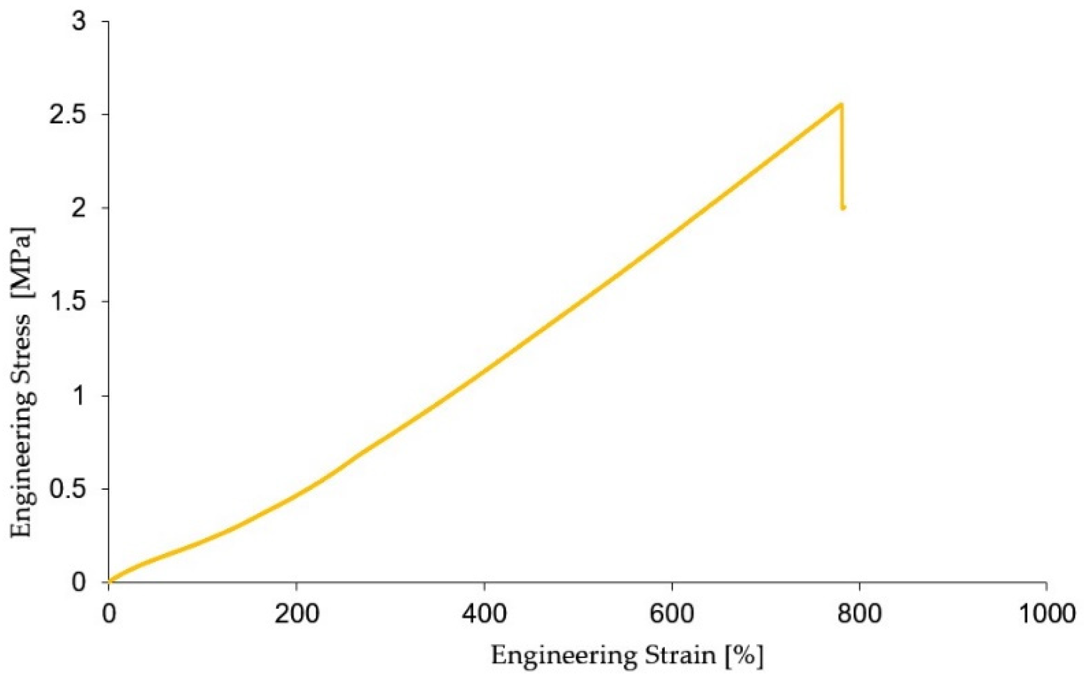
25]. The dimensions of the specimens are 3 mm in thickness, a total length of 115 mm, where the length of the calibrated part is 33 mm, the width at the ends 25 mm, and the width of the calibrated part 6 mm. The tests were performed on a sample of 5 specimens on the Titan 2 Universal tensile testing machine (software version 7.0.4.14642) at a speed of 50 mm/min and with a cell force of 600 N. From the experimental data obtained, for the accuracy of the results, outliers were removed. Based on the experimental results taken from the machine software, the characteristic curve in the form of engineering stress and engendering strain was plotted, the curve representing the average of the values of the 5 specimens tested, the test results are shown in
Figure 4.
The experimental data obtained from the tensile tests provides the possibility of determining a number of characteristics such as material elongation, Young’s modulus of elasticity, and material constants needed to perform finite element simulation of the actuator. This is needed to determine the approximate behavior of the actuators tested. Also, an important aspect that was considered was to identify the actuating pressure required for the actuators to achieve amplitude of motion values as close as possible to the phalanx amplitude of motion values. In the case of the PIP joint, this amplitude is approximately 120º. Achieving a value as close as possible to the actual phalangeal range of motion values leads implicitly to greater efficiency and to a shorter recovery time.
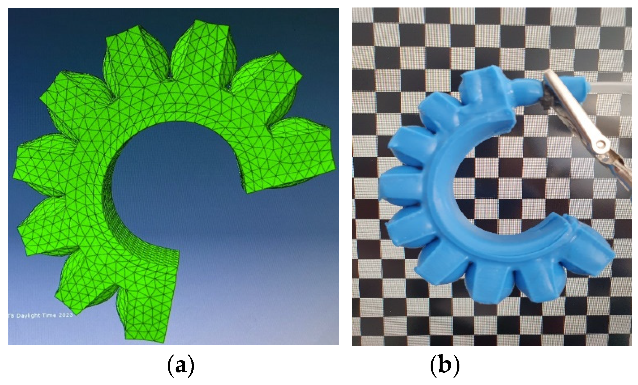
Obtaining this information was done using the finite element program Abaqus (Dassault Systems - 6.13-1), the simulation is identified in
Figure 5 (a). Modeling of the PneuNets actuators was performed using the Yeoh hyperelastic model [
26], for non-linear and incompressible materials based on the experimental data of the graph in
Figure 4 engineering stress and engendering strain. The strain energy function for determining the 2nd-order material constants is shown below in equation 1:
The values of the Yeoh material constants of degree 2 obtained are C
10 = 48.673 (Pa), C
20 = 962.03 (Pa). From the simulations, it can be seen compared to
Figure 5 (b) that the simulated bending amplitude is approximately equal to the actual bending amplitude.
2.3. Relationship between pressure/angle/force in bending phase
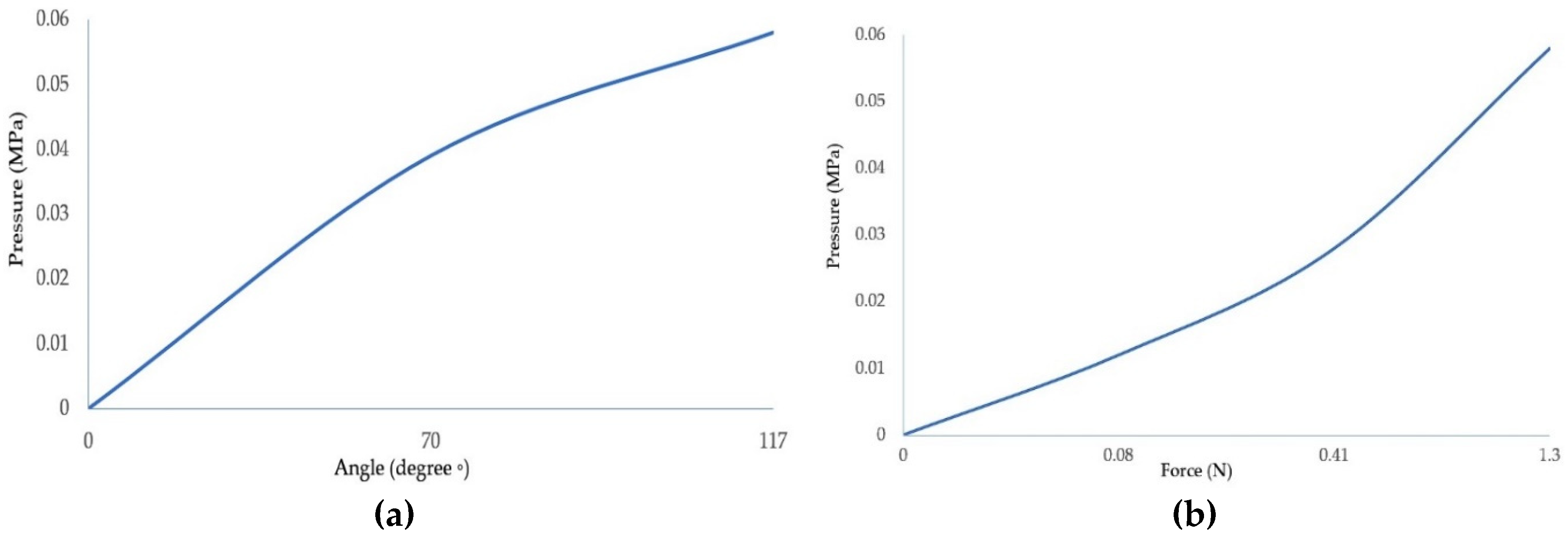
To identify the characteristics that hold the actuating pressure, the amplitude of movement, and the force that the actuator can develop at different input pressures, an experimental test was carried ou
t. Thus, two graphs
Figure 6 (a), (b) were made in which the output characteristics, namely the bending angle and the force as a function of the input pressure, were determined.
Determination of the bending angle so that the value is as close as possible to the amplitude of the natural motion was done according to the inlet pressure. A resistive flex sensor was used and integrated between the actuator layers as shown in Figure 8. This sensor provides relatively accurate information about the angular position of the actuator as a function of the pressure inside the actuator chamber. We have used the Honeywell ABPDANV150PGSA3 pressure sensor which has a pressure range of 0 - 150 psi. From the graph in
Figure 6 (a) it can be seen that at a pressure of 0.06 MPa an actuator deflection value of 117º is obtained, which represents an amplitude similar to that of the PIP joint. Regarding the output force as a function of the input pressure, the force was measured using a force-sensing resistor. The force was measured at the distal end of the actuator, the characteristic curve is shown in
Figure 6 (b), where it can be seen that at an input pressure of 0.06 MPa, the output force of the actuator is 1.3 N.
2.4. Pneumatic glove control system
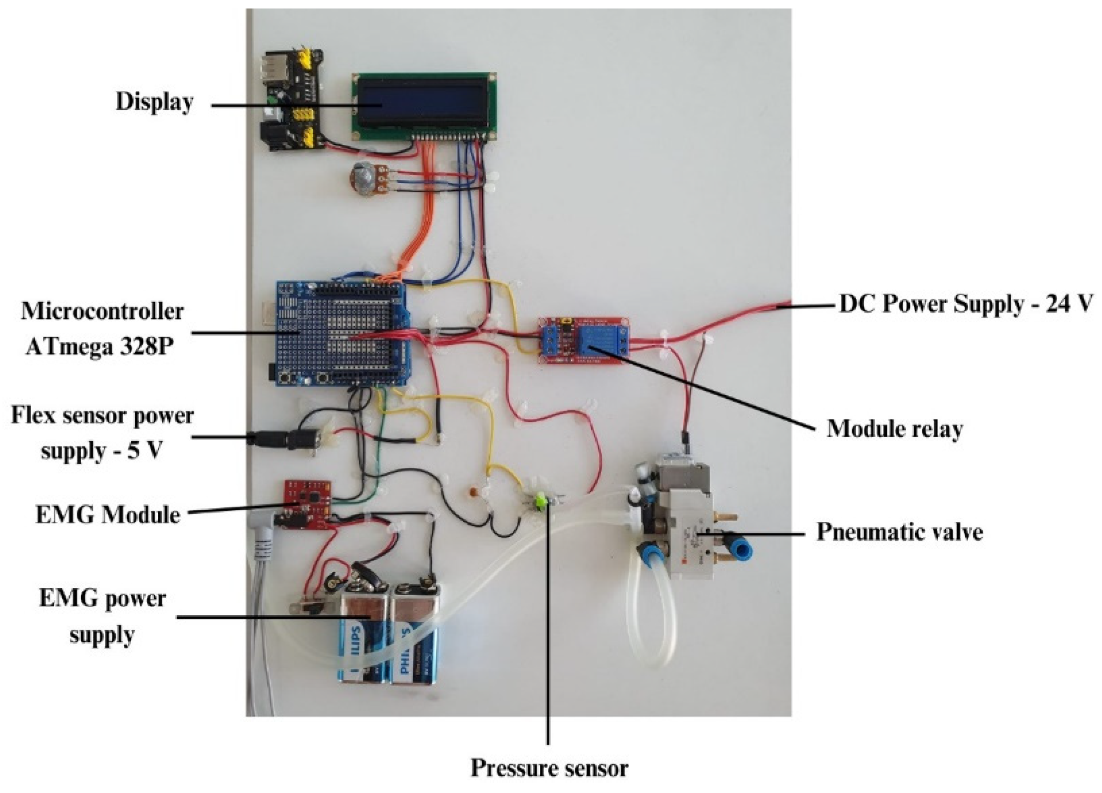
As far as the control of the soft glove is concerned, a control unit has been developed which is shown in
Figure 7. This control unit allows the supply of the simultaneous actuators through a pneumatic control system which is composed of an electro-pneumatic valve (SMC - SYJ5120 – 24 V) that allows the pressurization and depressurization of the actuators, pressure sensors (Honeywell - ABPDANV150PGSA3) and the pressure supply is taken from an air compressor. As for the control system, it consists of a development board equipped with a microcontroller (ATmega 328P), control relay, EMG module with three surface electrodes, a display for displaying information related to the number of repetitions performed by the patient, the pressure inside the actuators as well as data from the flex sensor integrated in the actuator layers (gradeº). Since several voltage levels are required to supply the components, both pneumatic and control, 12 V and 24 V voltage regulators were used respectively.
3. Results
3.1. Integration of actuators within wearable gloves
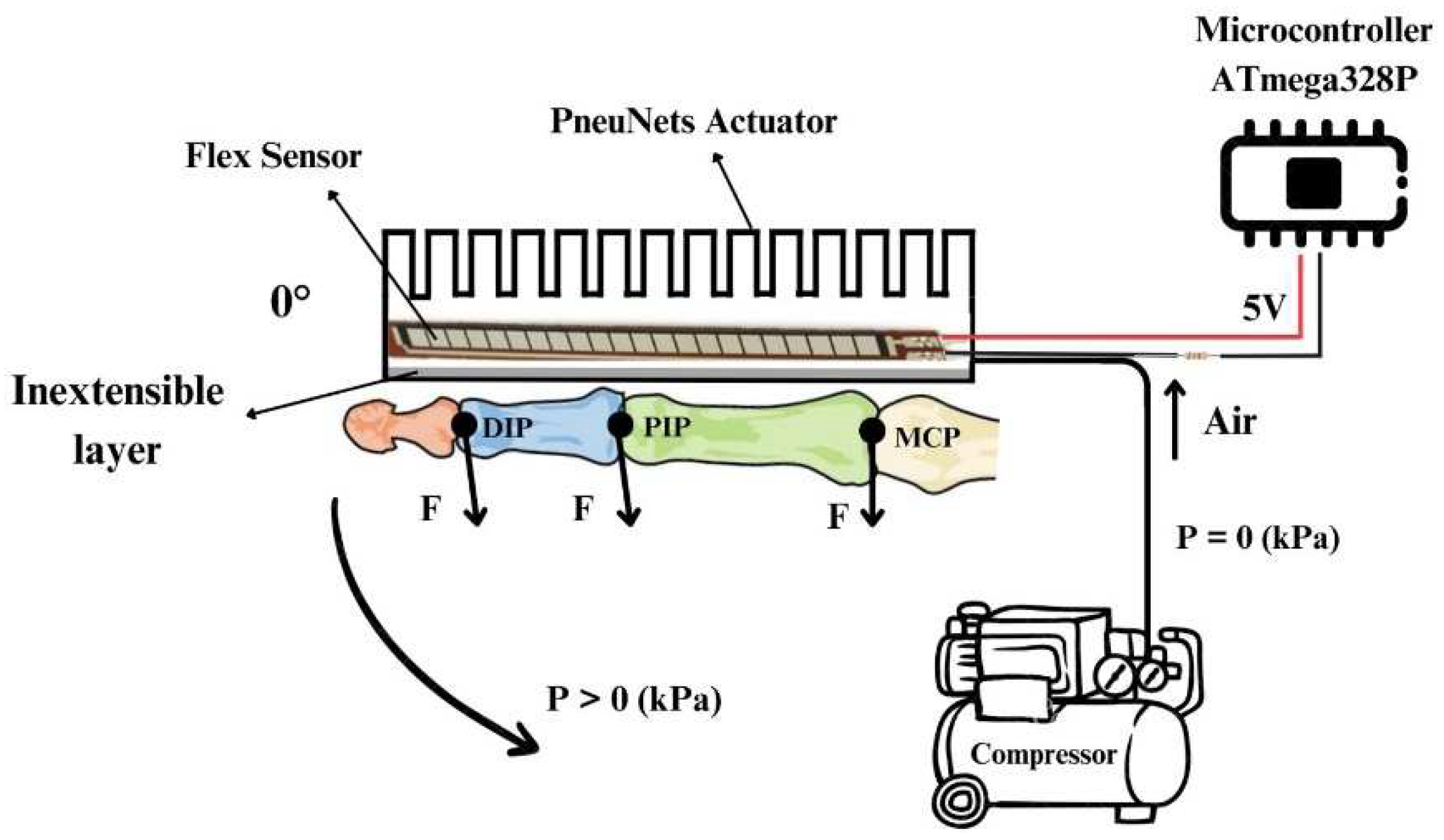
The wearable device with wearable glove-type soft actuators is based on PneuNets actuators that perform the specific bending motion by driving the phalanges of the 5 fingers in flexion. The schematic diagram of the operation is shown in
Figure 8, where the positioning of the actuator on the dorsal side of the hands can be seen. The actuators are connected through hoses to the compressor, and when the pressure is higher than 0, the actuator starts to perform a bending movement by flexing the phalanges. Between the layers of the actuator, the flex sensor (FS, Spectra Symbol, USA) is positioned, which monitors the amplitude of the flexing movement.
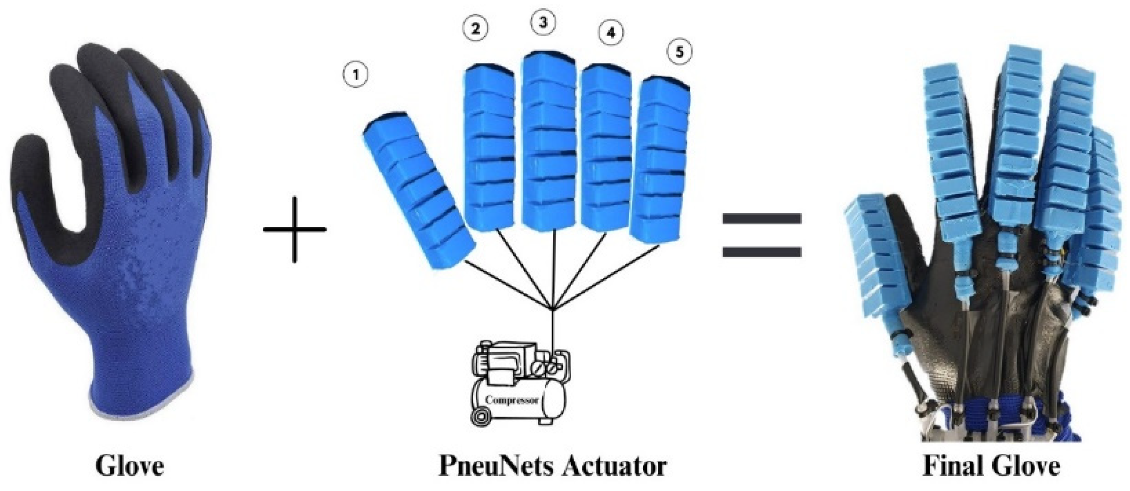
The soft actuator wearable consists of a textile glove with an elastomer layer on the palm for a better grip due to the higher coefficient of friction between the glove and objects. As far as the attachment of the glove actuators is concerned, it has been considered that the grip should influence their behavior as little as possible. That is why the choice was made to fix the actuators using nylon fibers, which offer good stability over time as well as minimal impact on the actuator. Actuator supply hoses with a diameter of 4 mm were used, and to avoid pressure losses from the inside, a silicone rubber zone was made at the inlet end of the hose into the actuator. The components of the wearable soft actuator glove device are shown in
Figure 9.
A medium-sized glove was used to cover as wide a range of patients as possible. In stroke patients, anthropometric dimensions are smaller due to muscle atrophy. However, the size of the actuators as well as the glove can be adapted according to these anthropometric data.
3.2. Control strategy based on EMG signals
The wearable device relies on actuators controlling an EMG controller (EMG Sensor Controller) that captures the muscle signal from the forearm to identify the user’s intention to perform a certain action. The EMG module consists of a signal processing unit and three gel surface electrodes that are positioned in the muscle area of interest (Flexor Digitorum Superficialis - FDS) of the forearm. Before positioning the surface electrodes, the skin was cleaned with medical alcohol to ensure that there were no layers of fat or impurities that would prevent or alter the quality of the captured signal. The EMG module provides an analog output signal between 0 V and 9 V and has a supply voltage between 3.5 V and 9 V - DC, the module is based on an integrated H124SG. The device control strategy based on control using EMG is one of relatively low complexity but has provided satisfactory results in the rehabilitation phases. For example, if the patient intends to grip a target, the electrical signal of the muscles is continuously monitored and when the signal amplitude exceeds a certain amplitude value (this is pre-set in advance for each patient), the electro valve opens, supplying the 5 actuators that drive the fingers in flexion movement with pre-selected power. The pressure supply to the actuators is switched off when the flex sensor value reaches approximately 120º. When this value is reached the actuators will be held in this position for two seconds, this is made possible by switching the solenoid valve to the intermediate position. After two seconds, the solenoid valve will open and depressurize the actuators. If controlled depressurization is desired, the solenoid valve will switch between the intermediate and open position. When the amplitude value of the EMG sensor exceeds that value again, the above steps are repeated.
3.3. Rehabilitation/assistance training using the wearable device
Rehabilitating stroke patients’ hands to regain mobility and the ability to perform daily activities involves rehabilitation training based on repeated flexion/extension movements of the hands. Our tests were performed on healthy subjects who have residual EMG signals on the forearm muscles, being able to easily implement EMG signal-based control with high signal amplitudes. In patients who have suffered strokes or other neurological diseases, the residual EMG signals in the forearm area are relatively low, making it difficult to capture and process the signal, in which case there is the possibility of positioning the EMG electrodes on the biceps muscle area as it has a higher density of muscle fibers and therefore higher signal amplitudes for control. Based on this, it was decided to perform rehabilitation training consisting of several sets of flexion/extension finger movements with an amplitude of approximately 120º. Prior to the start of the rehabilitation training, the patient is placed with gel surface electrodes on the FDS muscle of the forearm corresponding to flexion/extension finger movements. The surface has been degreased beforehand, and the analog value from which the actuator pressurization will start is determined based on the patient’s varying signal. Actuator pressurization is done up to a value of 0.06 MPa and a movement amplitude of approximately 120º, monitored by the flex sensor. All this data is displayed in real time together with the number of repetitions performed by the patient on the display of the control unit. Closed-loop control provides good and efficient controllability of the wearable device for flexion/extension finger movement training. Once the analog value is set according to the patient, the wearable device is positioned on the patient’s hand so that it provides comfort to the patient. After positioning the device, the rehabilitation training may stop when the set analog value of the EMG signal is exceeded.
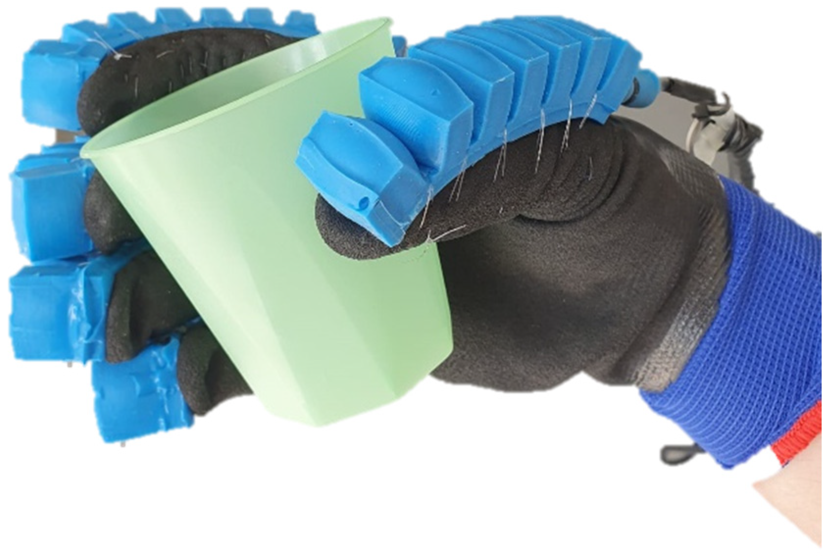
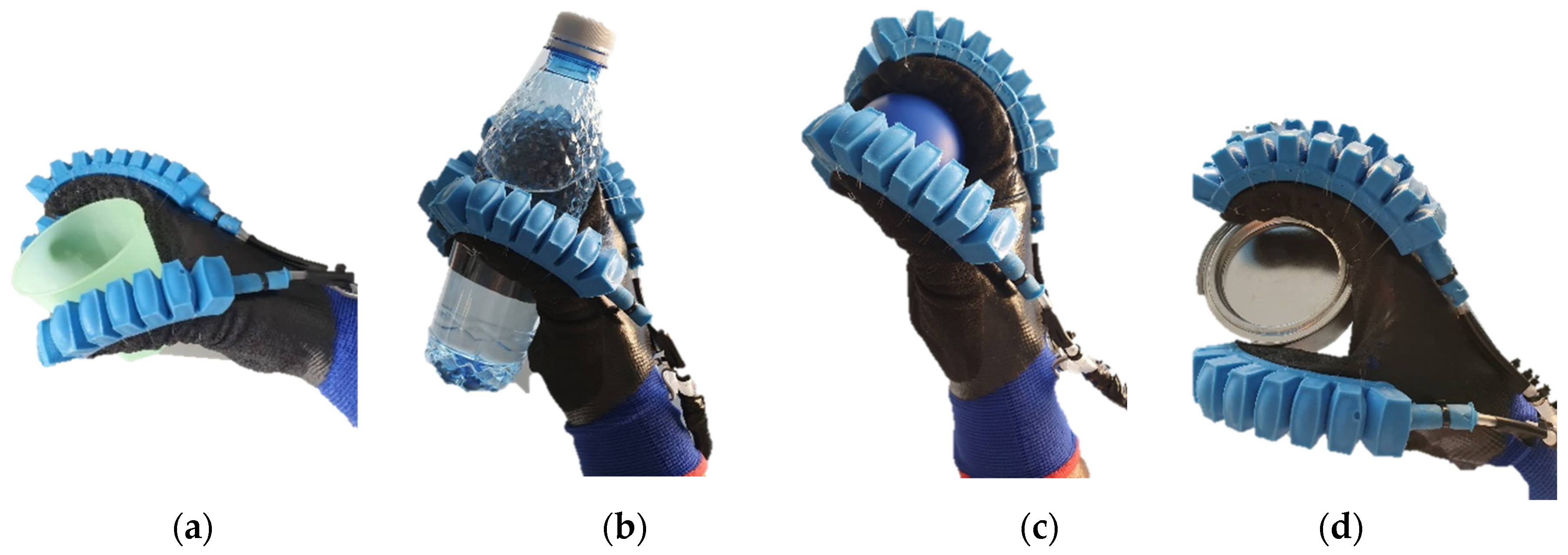
Regarding the use of the wearable device for hands-on assistance in everyday activities, a series of tests were conducted on different objects to identify the potential of such a device. The two cases of rehabilitation and assistance share some similarities in this case, namely from the perspective of the movements performed by the patient (flexion/extension), therefore the testing of the device in the cases of assistance on different objects with different geometries was approached. The tests can be identified below in
Figure 10.
Several objects with different geometries were tested, representing objects that are more commonly identified in a home and with which patients are most likely to interact. These objects also have different mass, namely plastic cup (42 g)
Figure 10 (a), water bottle (280 g) Figure (b), ball (17 g)
Figure 10 (c) and cylindrical piece (110 g)
Figure 10 (d). For gripping these objects, all 5 fingers were pressurized with a lower amount of pressure than in the rehabilitation case. From the tests performed, the device offers good flexibility, but the limiting aspects are related to the control unit which offers a reduced working space due to the length of the actuator cable, this being an important future direction.
4. Conclusion and future works
Due to the social context in which an increasing number of people suffer strokes or other neurological diseases that leave them with various impairments affecting mobility, especially that of the upper limbs, it is necessary to carry out rehabilitation training to regain mobility and perform activities of daily living (ADL) again. In this current context, the present work addressed the realization of a wearable exoskeleton-type device for the upper limb to assist the patient during rehabilitation exercises, as well as the possibility of assisting in different daily activities, offering the possibility of re-enabling them in the personal environment. The device provides active rehabilitation/assistance, being based on capturing the patient’s muscle intention within the forearm muscles. PneuNets actuators provide flexion motion actuation of the phalanges (DIP, PIP, MCP) for fingers 2 - 5 and (IP, MCP) for finger 1, and the extension motion is passively controlled by depressurizing the actuators. Two different actuator lengths were used depending on the anatomical dimensions of the fingers. A rigorous procedure was followed for the manufacture of the actuators, based on a series of steps to ensure that the actuators would be consistent and reliable over a long period. The two main manufacturing technologies in the field of soft robotics were used, namely casting and 3D-printing to make the casting mold. Two-component elastomeric material (RTV ZA 22A) with a Shore hardness of 22A was subjected to uniaxial tensile testing until breakage to determine the material’s mechanical characteristics and to perform FEA simulation based on material constants. It was taken into account that the actuator performs the bending motion with an amplitude approximately equal to the amplitude of motion of the PIP joint, so the actuator behavior was determined as a function of the input pressure, and the degree of bending of the actuator was monitored with a flex sensor as well as the output force developed by the actuator. At a pressure of 0.06 MPa, the bending angle is 117º and the force developed is 1.3 N. The control unit of the wearable device is mainly based on microcontroller-based information processing electronics and flow control elements such as pneumatic valves that distribute fluid to actuators. The exoskeleton-type wearable device has a relatively simple structure consisting of a textile glove with a silicone rubber on the palmar area to improve grip and PneuNets actuators which are positioned on the back of the hands using nylon fibers. The wearable device is mainly intended for active rehabilitation of the patient’s hands, but it is also possible to assist in various daily activities. The tests were performed on healthy subjects and were mainly based on a series of flexion/extension movements of the fingers in the three joints (DIP, PIP, MCP, and IP), as well as through the use of different objects with different geometries and masses. These movements are based on the capture of the patient’s muscle intention through EMG surface electrodes.
As future directions, the authors intend to increase the modularity and flexibility of the control unit, as currently, this unit brings some limitations in terms of its volume as well as its portability, also limiting the patient’s room for action in case of assistance. Another issue the authors are considering as a future direction is related to the integration of the wearable device with virtual reality (VR) and LeapMotion controller. By using VR and the LeapMotion controller, a series of specific rehabilitation games can be made tailored to the patient’s needs. The LeapMotion controller as an immersive element in VR provides the possibility for the patient to interact with different objects in VR, improving motivation and the level of interaction. Another aspect that the authors wish to develop is the integration of the wearable glove into a wearable upper limb device that assists both the wrist (flexion/extension and abduction/adduction) and the elbow joint in flexion/extension movement. It is also intended to validate the device by performing tests on patients with hand movement impairments due to stroke or other neurological diseases.
Author Contributions
Conceptualization, D.-M.R. C.-M.B. and S.-G.R.; methodology, D.-M.R., C.-E.G. and R.-D.G.; writing—original draft preparation, D.-M.R. and C.-M.B.; writing—review and editing, D.-M.R., C.-M.B. and R.-D.G.; supervision, C.-M.B. and S.-G.R. All authors have read and agreed to the published version of the manuscript.
Funding
Please add: This research received no external funding.
Acknowledgments
This project is funded by the Ministry of Research, Innovation and Digitization through Program 1 - Development of the National Research and Development System, Subprogram 1.2 - Institutional Performance - Funding Projects for Excellence in RDI, Contract No. 28PFE/30.12.2021.
Conflicts of Interest
The authors declare no conflict of interest.
References
- Benjamin, E. J. , Blaha, M. J., Chiuve, S. E., Cushman, M., Das, S. R., Deo, R., de Ferranti, S. D., Floyd, J., Fornage, M., Gillespie, C., Isasi, C. R., Jiménez, M. C., Jordan, L. C., Judd, S. E., Lackland, D., Lichtman, J. H., Lisabeth, L., Liu, S., Longenecker, C. T., Mackey, R. H. American Heart Association Statistics Committee and Stroke Statistics Subcommittee. Heart Disease and Stroke Statistics-2017 Update: A Report From the American Heart Association. Circulation 2017, 135. [Google Scholar] [CrossRef]
- Roger, V. L. , Go, A. S., Lloyd-Jones, D. M., Benjamin, E. J., Berry, J. D., Borden, W. B., Bravata, D. M., Dai, S., Ford, E. S., Fox, C. S., Fullerton, H. J., Gillespie, C., Hailpern, S. M., Heit, J. A., Howard, V. J., Kissela, B. M., Kittner, S. J., Lackland, D. T., Lichtman, J. H., Lisabeth, L. D. American Heart Association Statistics Committee and Stroke Statistics Subcommittee. Heart disease and stroke statistics--2012 update: a report from the American Heart Association. Circulation 2012, 125. [Google Scholar] [CrossRef]
- Kwakkel G, Kollen BJ, van der Grond J, et al. Probability of regaining dexterity in the flaccid upper limb: impact of severity of paresis and time since onset in acute stroke. Stroke 2003, 34, 2181–2186. [CrossRef]
- Kong KH, Chua KS, Lee J. Recovery of upper limb dexterity in patients more than 1 year after stroke: frequency, clinical correlates and predictors, Neurorehabilitation 2011, 28, 105–111.
- Langhorne P, Bernhardt J, Kwakkel G. Stroke rehabilitation. Lancet 2011, 377, 1693–1702. [Google Scholar] [CrossRef]
- Harris JE, Eng JJ. Strength training improves upper-limb function in individuals with stroke: a meta-analysis. Stroke 2010, 41, 136–140. [CrossRef] [PubMed]
- Woo J, Chan SY, Sum MWC, et al. In patient stroke rehabilitation efficiency: influence of organization of service delivery and staff numbers. BMC Health Serv Res 2008, 8, 86. [Google Scholar]
- Maciejasz P, Eschweiler J, Gerlach-Hahn K, et al. A survey on robotic devices for upper limb rehabilitation. J Neuroeng -Rehabilitation 2014, 11, 3. [CrossRef] [PubMed]
- Butzer, T. , Dittli, J., Lieber, J., van Hedel, H. J. A., Meyer-Heim, A., Lambercy, O., & Gassert, R. (2019). PEXO - A Pediatric Whole Hand Exoskeleton for Grasping Assistance in Task-Oriented Training. IEEE 16th International Conference on Rehabilitation Robotics (ICORR) 2019. [Google Scholar] [CrossRef]
- Bützer, T. , Lambercy, O., Arata, J., & Gassert, R. Fully Wearable Actuated Soft Exoskeleton for Grasping Assistance in Everyday Activities. Fully Wearable Actuated Soft Exoskeleton for Grasping Assistance in Everyday Activities. Soft Robotics 2020. [CrossRef]
- Chiri, A. , Giovacchini, F., Vitiello, N., Cattin, E., Roccella, S., Vecchi, F., & Carrozza, M. C. (2009). HANDEXOS: Towards an exoskeleton device for the rehabilitation of the hand. IEEE/RSJ International Conference on Intelligent Robots and Systems, 2009. [Google Scholar] [CrossRef]
- Ho, N. S. K. , Tong, K. Y., Hu, X. L., Fung, K. L., Wei, X. J., Rong, W., & Susanto, E. A. An EMG-driven exoskeleton hand robotic training device on chronic stroke subjects: Task training system for stroke rehabilitation. IEEE International Conference on Rehabilitation Robotics, 2011. [Google Scholar] [CrossRef]
- M. Crenganis, R. M. Crenganis, R. Breaz, G. Racz and O. Bologa, Adaptive neuro-fuzzy inference system for kinematics solutions of redundant robots. 6th International Conference on Computers Communications and Control (ICCCC) 2016, pp. 271–276. [CrossRef]
- G. Robinson and J. B. C. Davies. Continuum robots - a state of the art. Proceedings, IEEE International Conference on Robotics and Automation (Cat. No.99CH36288C) 1999, Detroit, MI, USA, Volume. 4, pp. 2849–2854. [CrossRef]
- Cappello, L. , Meyer, J. T., Galloway, K. C., Peisner, J. D., Granberry, R., Wagner, D. A., … Walsh, C. J. Assisting hand function after spinal cord injury with a fabric-based soft robotic glove. Journal of NeuroEngineering and Rehabilitation 2018, 15. [Google Scholar] [CrossRef] [PubMed]
- Syrebo, hand rehabilitation glove. https://syrebocare.com/ro-ro?gclid=CjwKCAjw2K6lBhBXEiwA5RjtCTReFJ25EOt6RGTrd88rW4nJifEmqlK1bs0rVQKylTAE_585BlHGDxoCIzwQAvD_BwE, (Accessed in 10.07.2023).
- H. K. Yap et al., A Fully Fabric-Based Bidirectional Soft Robotic Glove for Assistance and Rehabilitation of Hand Impaired Patients, in IEEE Robotics and Automation Letters 2017, 2, 1383–1390. [CrossRef]
- P. Polygerinos, K. C. P. Polygerinos, K. C. Galloway, S. Sanan, M. Herman and C. J. Walsh, EMG controlled soft robotic glove for assistance during activities of daily living, IEEE International Conference on Rehabilitation Robotics (ICORR) 2015, Singapore, pp. 55–60. [CrossRef]
- Y. Wang, S. Kokubu, Z. Zhou, X. Guo, Y. -H. Hsueh and W. Yu, Designing Soft Pneumatic Actuators for Thumb Movements. IEEE Robotics and Automation Letters 2021, 6, 8450–8457. [CrossRef]
- Min Pan, Chenggang Yuan, Xianrong Liang, Tianyun Dong, Tao Liu, Junhui Zhang, Jun Zou, Huayong Yang, Chris Bowen, Soft Actuators and Robotic Devices for Rehabilitation and Assistance, Advanced Intelligent Systems 2021. [CrossRef]
- Chu, C. Y. , & Patterson, R. M. (). Soft robotic devices for hand rehabilitation and assistance: a narrative review. Journal of neuroengineering and rehabilitation 2018, 15, 9. [Google Scholar] [CrossRef]
- Aubin, P.M. , Sallum, H.,Walsh, C., Stirling, L., and Correia, A. A pediatric robotic thumb exoskeleton for at-home rehabilitation: the Isolated Orthosis for Thumb Actuation (IOTA). IEEE Int. Conf. Rehabil. Robot, 2013. [Google Scholar] [CrossRef]
- Gasser, B. W. , and Goldfarb, M. Design and performance characterization of a hand orthosis prototype to aid activities of daily living in a poststroke population. Conf. Proc. IEEE Eng. Med. Biol. Soc. 2015, 3877–3880. [Google Scholar] [CrossRef]
- Rusu, D.-M.; Mândru, S.-D.; Biriș, C.-M.; Petrașcu, O.-L.; Morariu, F.; Ianosi-Andreeva-Dimitrova, A. Soft Robotics: A Systematic Review and Bibliometric Analysis. Micromachines 2023, 14, 359. [Google Scholar] [CrossRef]
- Standard Test Methods for Vulcanized Rubber and Thermoplastic Elastomers—Tension. Available online: https://www.astm.org/d0412-16r21.html (accessed on 13 July 2023).
- Yeoh, O. H. , 1993. Some forms of the strain energy function for rubber. Rubber Chemistry and technology 1993, 66, 754–771. [Google Scholar] [CrossRef]
|
Disclaimer/Publisher’s Note: The statements, opinions and data contained in all publications are solely those of the individual author(s) and contributor(s) and not of MDPI and/or the editor(s). MDPI and/or the editor(s) disclaim responsibility for any injury to people or property resulting from any ideas, methods, instructions or products referred to in the content. |
© 2023 by the authors. Licensee MDPI, Basel, Switzerland. This article is an open access article distributed under the terms and conditions of the Creative Commons Attribution (CC BY) license (http://creativecommons.org/licenses/by/4.0/).
