Submitted:
31 July 2023
Posted:
02 August 2023
You are already at the latest version
Abstract
Keywords:
1. Introduction
2. Principle and Method of Electromagnetic Ultrasonic Testing
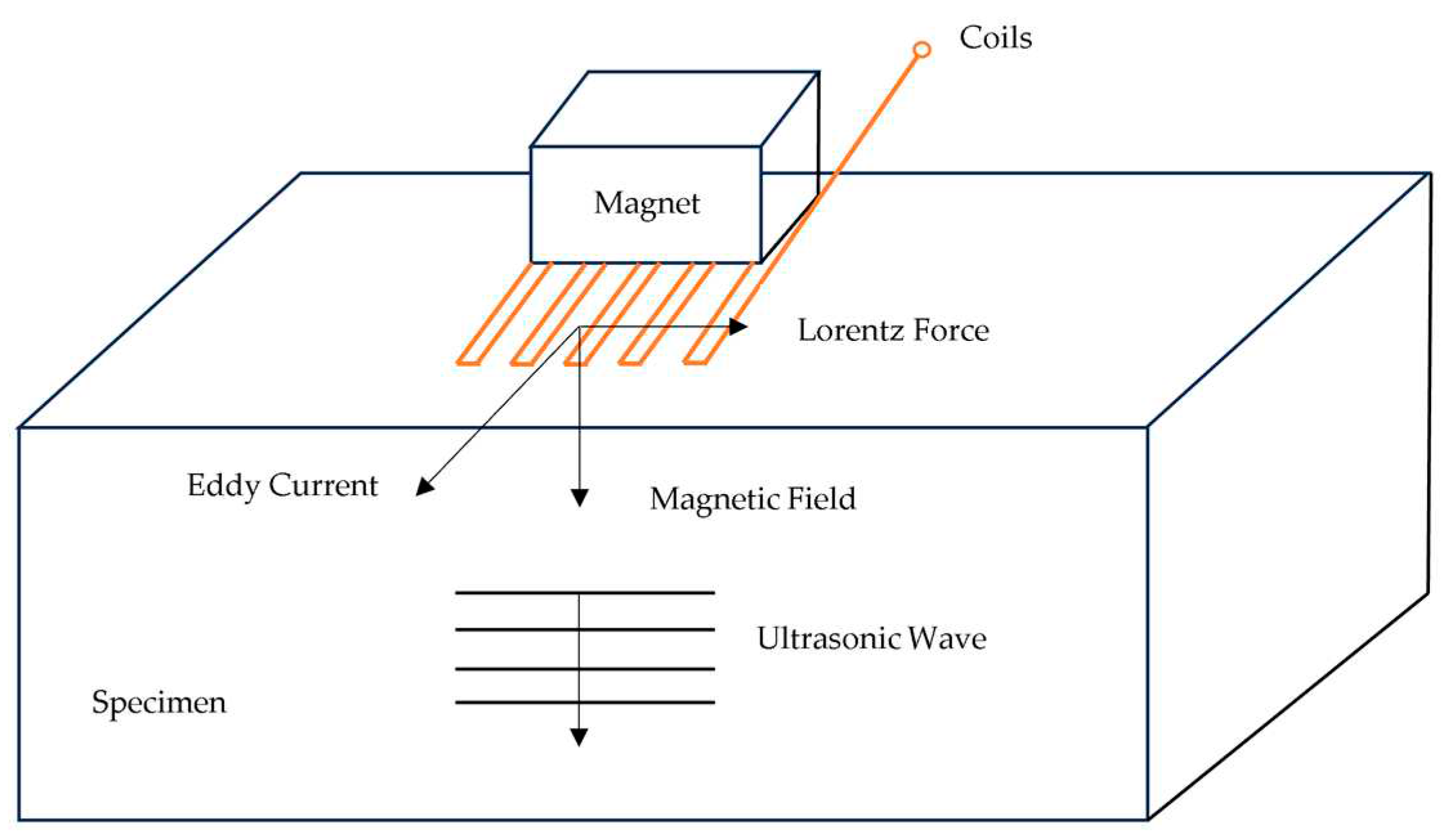
2.1. Basic Principles of Electromagnetic Ultrasonic Testing
2.2. Antenna Wheel-Rail Electromagnetic Ultrasonic Inspection Mechanism
3. Numerical Simulation and Result Analysis
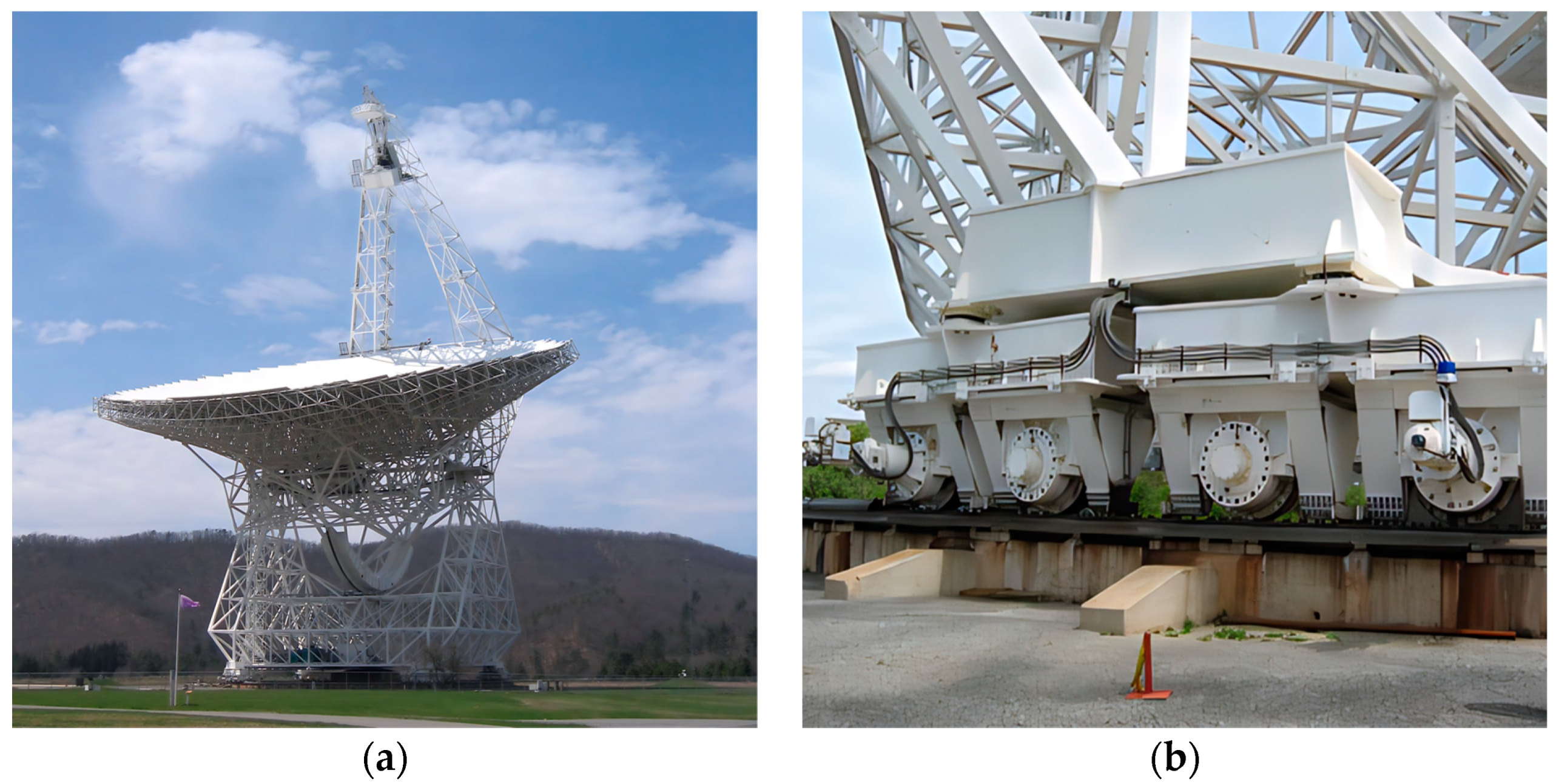
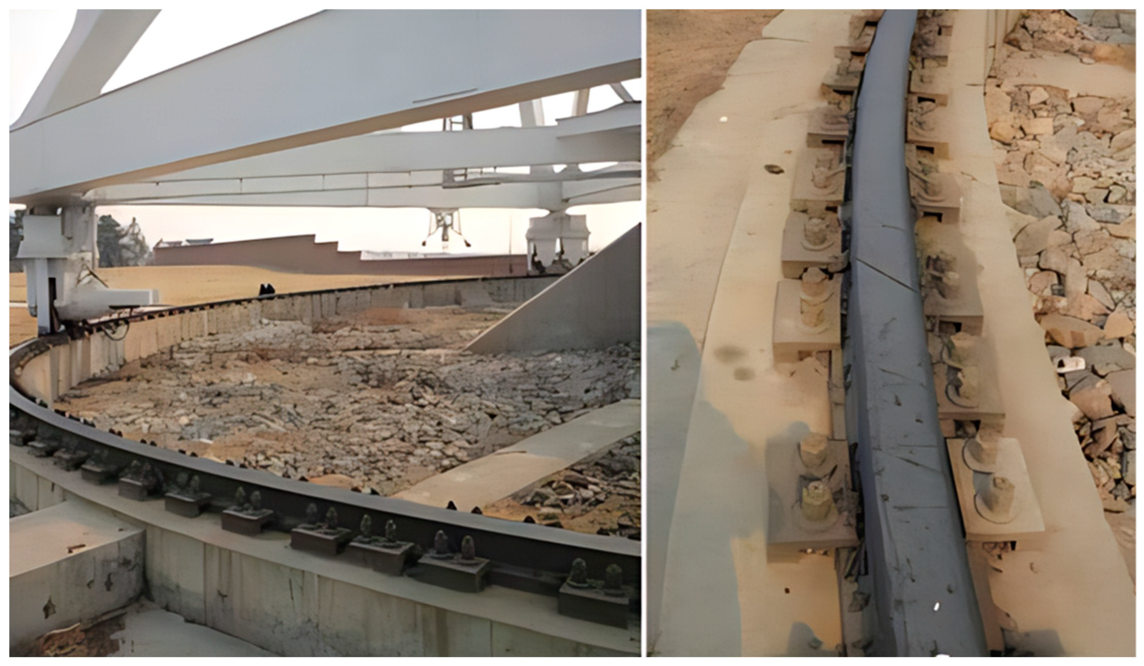
3.1. Antenna Wheel-Rail and Damage Forms
- Wheel-rail wear: wheel-rail surface contact force is too large, the roller in the track after a long period of operation will produce track surface wear, reduce the precision of the track;
- fatigue cracks: roller and track long-term role, a point of stress concentration, gradually sprouting cracks;
- wheel-rail corrosion: by the working environment as well as the influence of climate, the track surface is corroded, which seriously affects the precision of the wheel-rail, thus affecting the normal work of the antenna.
3.2 Construction of The Wheel-Rail Model
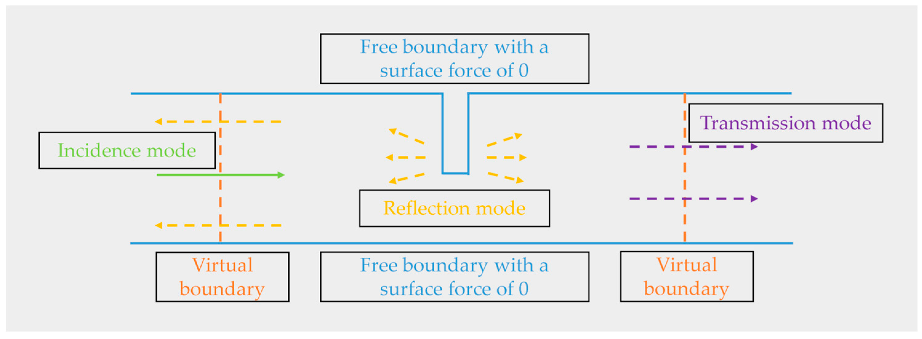
3.3 Electromagnetic Ultrasonic Excitation Process
- Establish a simplified geometric model of the antenna wheel-rail. A low-reflection boundary is applied to the left and right boundaries of the model, and the reflections from the structural boundaries are neglected. The grid is divided into more than three layers in the skin depth, and other parts are appropriately coarsened;
- Establish the electromagnetic field model. Set the appropriate step size and error in the transient solution to ensure the correctness and stability of the solution;
- Establish the acoustic field model. This part uses the solid mechanics module to add the Lorentz force to realize the transformation of magnetic field to force field;
- Multi-physics field coupling setup. The Lorentz force coupling setup is performed within the skin convergence depth of the specimen. The conversion of electric field-magnetic field-force field is realized by the above operations. The finite element simulation principle is shown in Figure 7.
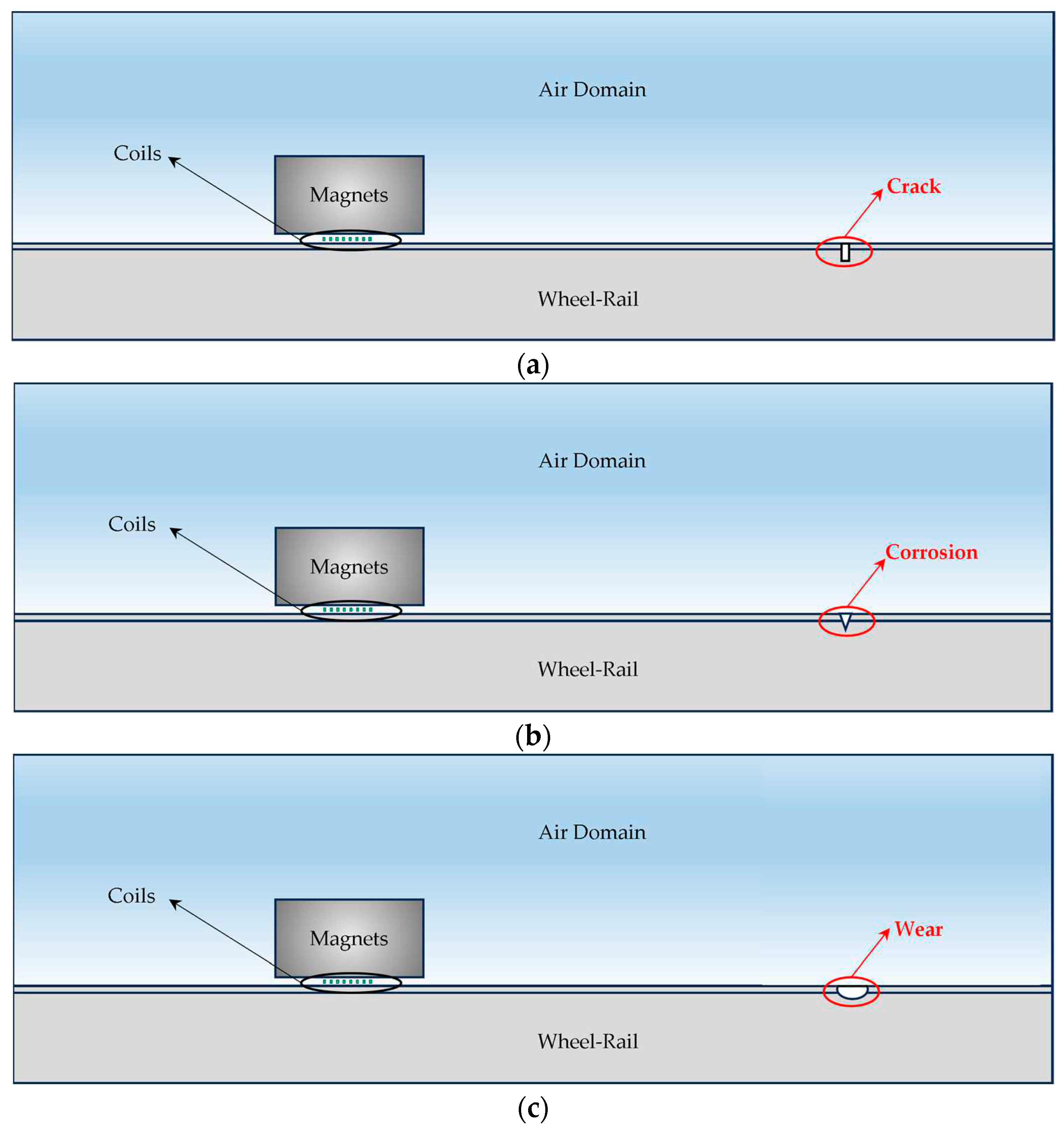
3.4 Setting of Wheel-Rail Surface Damage
3.5 Wheel-Rail Damage Detection and Analysis
4. Conclusions
Author Contributions
Funding
Data Availability Statement
Acknowledgments
Conflicts of Interest
References
- de Pater, I.; Molter, E.M.; Moeckel, C.M. A Review of Radio Observations of the Giant Planets: Probing the Composition, Structure, and Dynamics of Their Deep Atmospheres. Remote Sens. 2023, 15, 1313. [CrossRef]
- Wang, N. Xinjiang Qitai 110 m radio telescope. Scientia Sinica Physica, Mechanica & Astronomica. 2014, 44, 783-794. [CrossRef]
- Xu, Q.; Wen, H.X.; Wang, N.; Li, L. Development challenges for the Xinjiang 110 m radio telescope (QTT) high accuracy panel structures. Scientia Sinica Physica, Mechanica & Astronomica. 2017, 47, 8-18. [CrossRef]
- Gao, Y.L.; Wang, P.; Tian, G.Y.; Hao, S.S.; Xiong, L.H.; High-Speed Online Inspection Techniques of Rail Crack Defects Based on Electromagnetic Principle. NDT. 2012, 34, 1-11.
- Wan, S.G.; Kon, D.Q.; Chen, Z.P. Contact in Wheel-Rail Systems for Large Radio Telescopes: A Review. Astronomical Research and Technology. 2014, 11, 27-33.
- Liu, X.; AILI, Y.; Xiang, B.B.; Wang, C.S.; Xu, Q.; Wang, J. Analysis and Correction of the Influence of the Track Irregularity on Antenna Pointing. ACTA ASTRONOMICA SINICA. 2017, 58, 49-59.
- Wu, J.; Wang, B. Influence of track irregularity on the pointing accuracy for large reflector antenna. Journal of Terahertz Science and Electronic Information Technology. 2017, 15, 634-639.
- Kan, F.W.; Antebi, J. Slip and wear in multilayer azimuth track systems. Proceedings of SPIE. 2004, 549587. [CrossRef]
- Prestage, R.M.; Maddalena, R.J. The Green Bank Telescope: current status and early results. Large Ground-Based Telescopes. SPIE. 2003, 4837, 944-953. [CrossRef]
- Gu, J.X. Research on the antenna pointing error of 25m radio telescope. Annals of ShangHai Observatory Academia Sinica. 1994, 205-211.
- Anderson, R.; Symmes, A.; Egan, D. Replacement of the Green Bank Telescope azimuth track. Proceedings of SPIE the International Society for Optical Engineering. 2008, 63, 3026-3030.
- Symmes, A.; Anderson, R.; Egan, D. Improving the service life of the 100-meter green bank telescope azimuth track. In Ground-based and Airborne Telescopes. SPIE. 2008, 7012, 1225-1236. [CrossRef]
- Juneja, G.; Kan, F.W.; Antebi, J. Update on slip and wear in multi-layer azimuth track systems. Proceedings of SPIE. 2006, 627318. [CrossRef]
- Smith, D.R. Achievable alignment accuracy and surface hardness of a large welded azimuth track. Proceedings of SPIE. 2006, 627314. [CrossRef]
- Antebi, J.; Kan, F.W. Precision continuous high-strength Azimuth track for large telescopes. San Jose: International Society for Optics and Photonics. 2003, 612-623. [CrossRef]
- Guo, H.W. Analysis of Surface Crack on Wheel of a Rail Type Pedestal of Radar. Proceedings of the 2008 Electronic Machinery and Microwave Structure Technology Conference. 2008, 270-272.
- Kalker, J.J. On the rolling contact of two elastic bodies in the presence of dry friction. 1967.
- Kalker, J.J. Simplified theory of rolling contact. Delft Progress Rep. 1973, 1, 1-10. [CrossRef]
- Huray, P.Y. Maxwell's equations. John Wiley & Sons. 2011.
- Huang, S.L. Electromagnetic ultrasonic guided wave theory and application. Tsinghua University Press. 2013.
- Ribaric.; Marijan. Conservation laws and open questions of classical electrodynamics. Singapore: World Scientific. 1990. [CrossRef]
- Pei, C.; Fukuchi, T.; Zhu, H.; Koyama, K.; Demachi, K.; Uesaka, M. A study of internal defect testing with the laser-EMAT ultrasonic method. IEEE transactions on ultrasonics, ferroelectrics, and frequency control. 2012, 59, 2702-2708. [CrossRef]
- Wang, S.J.; Kang, L.; Li, Z.C.; Zhai, G.; Zhang, L. 3-D modeling and analysis of meander-line-coil surface wave EMATs. Mechatronics. 2012, 22, 653-660. [CrossRef]
- Zhang, Z.G.; Que, P.W.; Lei, H.M. Electromagnetic transducers for surface wave generation and their electroacoustic characteristics. Technical Acoustics. 2006, 25, 119-123.
- Cho, Y.; Rose, J. A Boundary Element Solution for a Mode Conversion Study on the Edge Reflection of Lamb Waves. Journal of the Acoustical Society of America. 1996, 99, 2097-2109. [CrossRef]
- Cho, Y.; Rose, J. An Elastodynamic Hybrid Boundary Element Study for Elastic Guided Wave Interactions with a Surface Breaking Defect. International Journal of Solids and Structures. 2000, 37, 4103—4124. [CrossRef]
- Kong, D.Q. National Astronomical Observatories 50-meter radio antenna. National Astronomical Observatories data. 2008.
- Xu, Q.; Hu, G.X.; Prediction of multi-layer and multi-pass welding Angle deformation under gravity bending moment of QTT antenna orbit. Transactions of The CHTNA Welding Institution. 2020, 41, 10-13+97-98.
- Shi, H.Q.; Xu, Q.; Wang, N.; Wang, Z.J. Finite Element Analysis of Wheel-on-track Rolling Contact for Large Aperture Radio Telescope. Astronomical Research & Technology. 2022, 19, 95-102.
- Liu, S.Z.; Dong, S.; Fang, Z.; Zhang, C. Tiny defect detection of aluminium plate by ultrasonic unidirectional surface electromagnetic wave. Technical Acoustics. 2019, 38(03).
- Liu, S.Z.; Wang, S.J.; Zhang, C.; Jin, L.; Yang, Q.X. Simulation Analysis of Electromagnetic Acoustic Surface Wave of Steel Plate and Quantitative Defect Detection. Transactions of CHINA Electrotechnical Society. 2020, 35, 97-105.
- Rose, J.; Shin, H.; Jeong, H. Detection of Defects in a Thin Steel Plate Using Ultrasonic Guided Wave. Proceedings of 15th World Conference on Non Destructive Testing, Rome. 2000.
- Ren, X.K.; Li, J. Simulation research on electromagnetic acoustic NDT by ANSYS. Electronic Measurement Technology. 2008, 31, 26-28.
- Bosso, N.; Magelli, M.; Zampieri, N. Simulation of wheel and rail profile wear: a review of numerical models. Railway Engineering Science. 2022, 30, 403-436. [CrossRef]
- Zhang, Y.S.; Huang, S.L.; Zhao, W. Detection System About Steel Cracks Based on Electronic Ultrasonic. NDT. 2009, 31, 307-310.
- Gharaibeh, Y.; Sanderson, R.; Mudge, P.; Ennaceur, C.; Balachandran, W. Investigation of the behaviour of selected ultrasonic guided wave modes to inspect rails for long-range testing and monitoring. Proceedings of the Institution of Mechanical Engineers, Part F: Journal of Rail and Rapid Transit. 2011, 225, 311-324. [CrossRef]


Disclaimer/Publisher’s Note: The statements, opinions and data contained in all publications are solely those of the individual author(s) and contributor(s) and not of MDPI and/or the editor(s). MDPI and/or the editor(s) disclaim responsibility for any injury to people or property resulting from any ideas, methods, instructions or products referred to in the content. |
© 2023 by the authors. Licensee MDPI, Basel, Switzerland. This article is an open access article distributed under the terms and conditions of the Creative Commons Attribution (CC BY) license (http://creativecommons.org/licenses/by/4.0/).


