Submitted:
01 August 2023
Posted:
03 August 2023
You are already at the latest version
Abstract
Keywords:
1. Introduction
2. Materials and Methods
2.1. Kinematic and Block Models of Series-Parallel PGSs
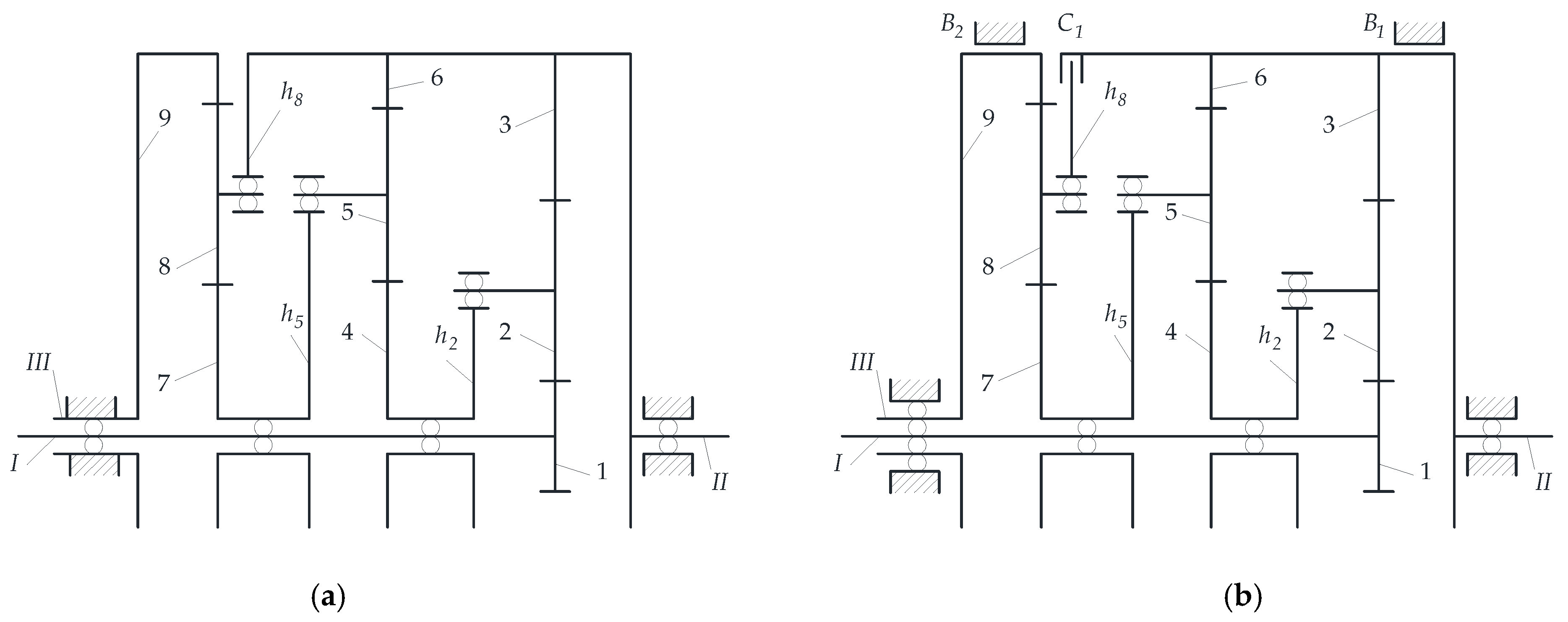
2.1.1. Geometric Structure of Series-Parallel PGSs
2.1.2. Decomposition of Series-Parallel Gear System into Subsystems
2.2. Analysis Algorithm of the Power Stream Flow in PGS without Power Loss
2.2.1. Method Algorithm
- (a)
- Gearbox geometry analysis—determination of gearbox mobility (1), decomposition of the gearbox into kinematic subsystems and their classification depending on the number of DoFs—Figure 2 and Figure 3, Section 2.2.2, Section 3.1, and Section 3.2;
- (b)
- Determination of the magnitudes and directions of angular velocities of gears and carriers in subsequent subsystems—Section 2.2.3 and Section 3.3.1 and Appendix A and Appendix B;
- (c)
- Determination of the magnitudes and directions of action of the torques loading the shafts of each of the subsystems (at this stage of calculation, without considering power losses)—Section 2.2.4 and Section 3.3.3 and Appendix C;
- (d)
- Determining the active and passive shafts of each of the transmission subsystems and the directions of the flow of power streams—Section 2.2.5, Section 3.3.4, and Section 3.3.5.
2.2.2. Analysis of the Geometry of Series-Parallel Gear Systems and Classification of Its Components
2.2.3. Analysis of the Kinematics of Series-Parallel Gears
2.2.4. Static Analysis without Considering Meshing Friction
2.2.5. Identification of Active and Passive Shafts and Power Flow Directions
- (1)
- For the driving shaft, the vectors of the angular velocity and the torque are in the same direction ();
- (2)
- For the driven shaft, the vectors of the angular velocity and the reaction torque are oppositely directed ().
3. Case Study
3.1. Case Study Subjects
3.2. Data
3.3. Power Flow Paths in PGS
3.3.1. Calculations of Angular and Tangential Velocities
3.3.2. Transmission Ratios on Power Flow Paths in Subsystems of Analysed PGS
3.3.3. Calculations of the Shaft Torques of Subsystems A, B, C
- Shaft torques of the two DoF subsystem A
- Shaft torques of the two DoF subsystem B
- Shaft torques of the single DoF subsystem C
3.3.4. Power Flow Paths in the Subsystems A, B, C of the PGS
- Identification of the power flow paths in type 2(a), 2(e) or 2(f) subsystem A
- Identification of the power flow path in the type 1(a) subsystem C
- Identification of the power flow path in analysed PGS (summary)
3.3.5. Powers and Power Ratios on the Shafts of Subsystems A, B, C of Analysed PGS
- Calculations of powers and power ratios on the shafts of subsystem A
- Calculations of powers and power ratios of subsystem B
- Calculations of powers and power ratios on the shafts of subsystem C
4. Results
5. Conclusions
- (1)
- The comparison of power flow paths and directions without considering power losses in two structurally similar PGSs, the first of which turned out to be structurally coupled (with a closed circuit) and dynamically coupled (with the power circulation phenomenon) during the analysis carried out in Part I, while the second PGS, analysed in part II, turned out to only be structurally coupled without power circulation;
- (2)
- The comparison of power flow paths and directions, considering power losses in gear meshing, and the determination of the power ratios and efficiency of these two PGSs (in Part III).
- (1)
- Checking the PGS mobility, dividing the PGS structure into blocks (subsystems) and closed circuits, and determining the fixed carrier transmission ratio of individual subsystems;
- (2)
- The determination of the magnitudes of the angular velocities of the gears and carriers, as well as gear ratios of the individual subsystems and PGSs using the Willis relationship;
- (3)
- Determining the magnitudes of the active and reactive torques, as well as the tangential and radial forces, using the free body diagram, which is necessary to calculate the active or reactive powers transmitted by the shafts of individual subsystems;
- (4)
- The determination of the paths with power flow directions by defining the role of individual subsystem shafts (active shafts—supplying power to the subsystem, passive shafts—discharging power from the subsystem)—an original method using the concepts of active and reactive torques, as well as active and reactive powers;
- (5)
- The calculation of power values and power ratios as a check of the algorithm.
Author Contributions
Funding
Conflicts of Interest
Appendix A
A.1. Willis formulas for subsystems A, B, C and PGS
- Equation for subsystem A (Figure B1):
- Equation for subsystem B (Figure B2):
- Equation for subsystem C (Figure B3):
A.2. Willis formulas for sun gear and planet gear pairs
- Equation for the sun gear 1 and the planet gear 2:
- Equation for the sun gear 4 and the planet gear 5:
- Equation for the sun gear 7 and the planet gear 8:
A.3. Calculations of angular velocities of gears and carriers of PGS
- Angular velocities of the carriers h2, h5 and h8:
- Angular velocities of the rim gear 3 and the sun gear 4:
- Angular velocities of the rim gear 6 and the sun gear 7:
- Angular velocity of the planet gear 2:
- Angular velocity of the planet gear 5:
- Angular velocity of the planet gear 8:
Appendix B
B.1. Calculation of tangential velocities of the gears of PGS
-
Assumption that the tangential velocities of the planet gears , , , , , are equal to the respective velocities of the sun and rim gears at their points of contact (according to Figure B1, Figure B2 and Figure B3):, , , , , .The calculated magnitudes of these velocities are given in Table B1.
| 1.385 | −1.372 | −0.229 | 0.256 | 0.047 | 0 |
B.2. Determination of instantaneous centre of zero velocity and velocities of the carrier
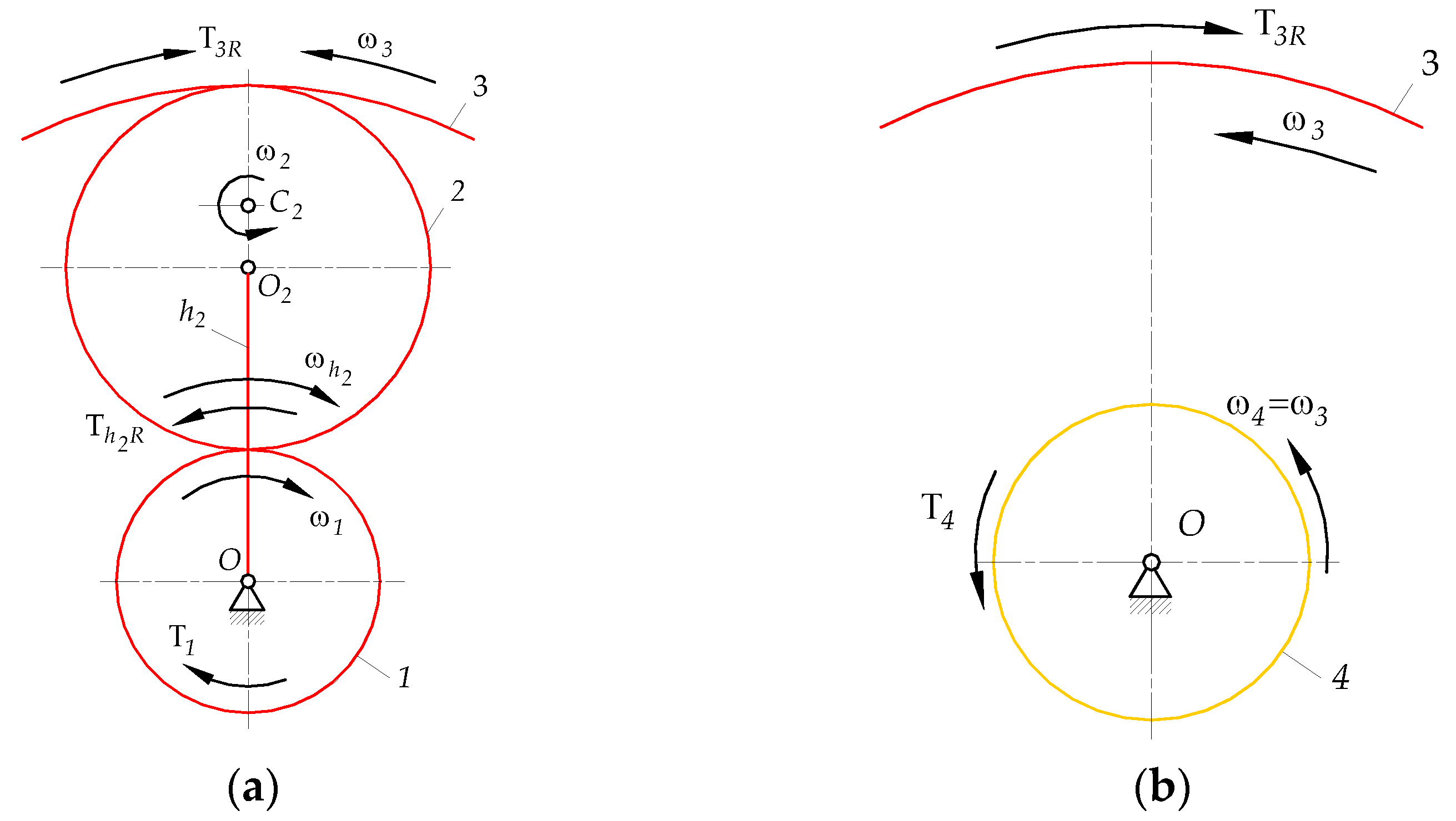
- The coordinate of the instantaneous centre of zero velocity of the planet gear 2 (Figure B1(a)):
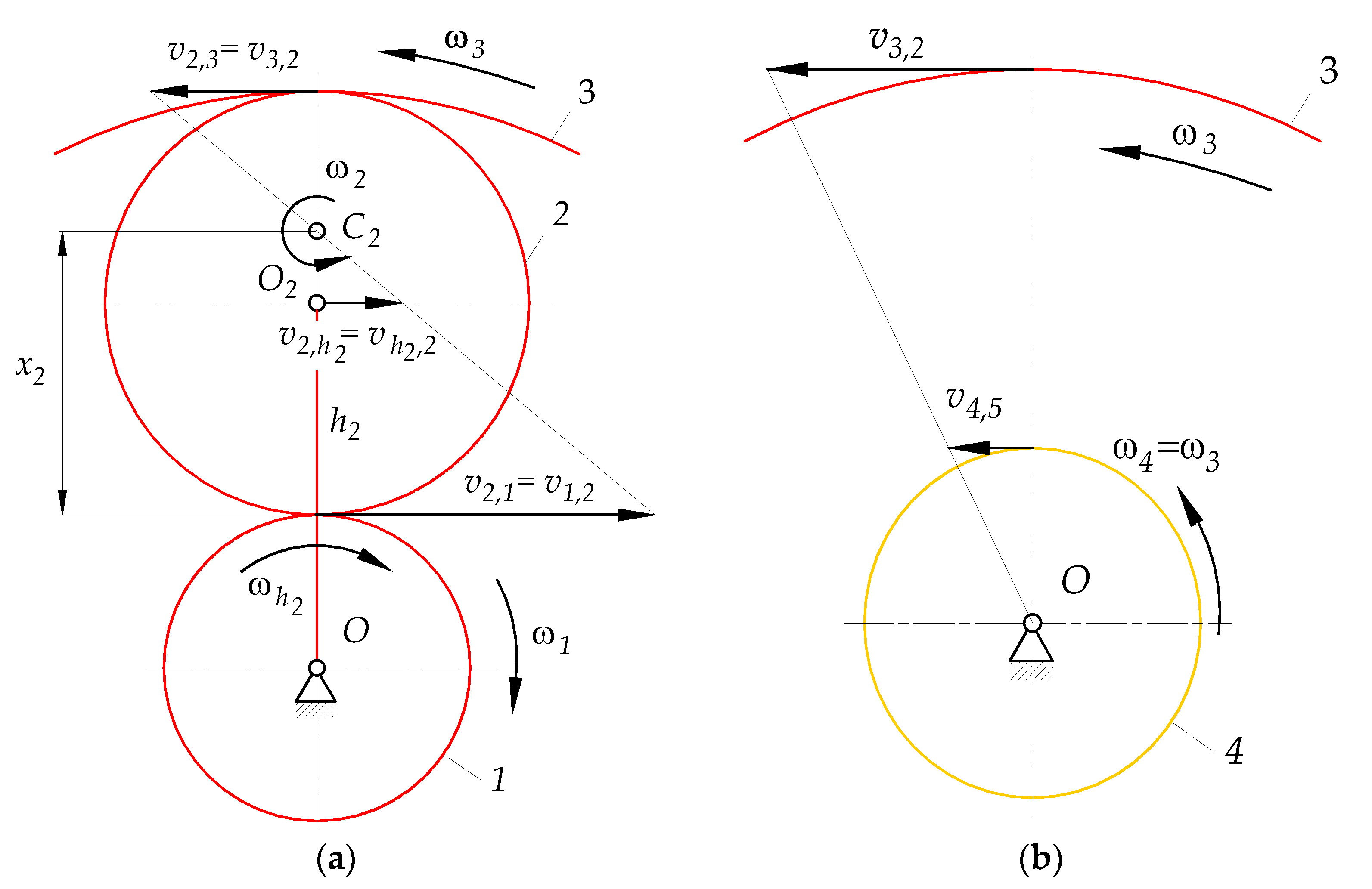
- Angular velocity of the planet gear 2 (check (A13)):
- Tangential velocities and of the centre of the planet gear 2 and the carrier , respectively (Figure B1(a)):
- Angular velocities of the carrier (Figure B1(a)):
- Tangential velocity of the sun gear 4 at the point of contact with the planet gears 5 (Figure B1(b)):
B.3. Determination of instantaneous centre of zero velocity and velocities of the carrier
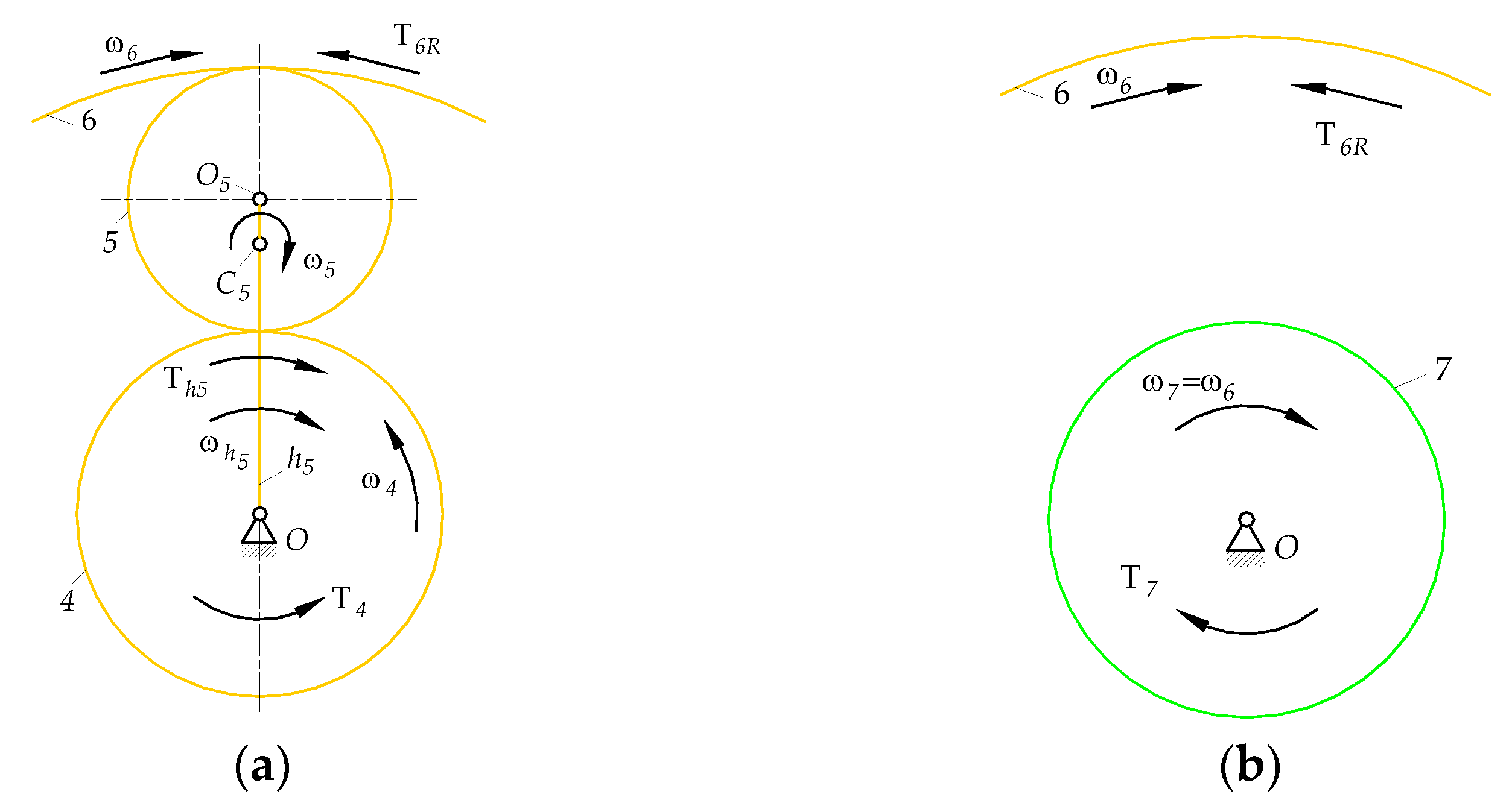
- The coordinate of the instantaneous centre of zero velocity of the planet gear 5 (Figure B2(a)):
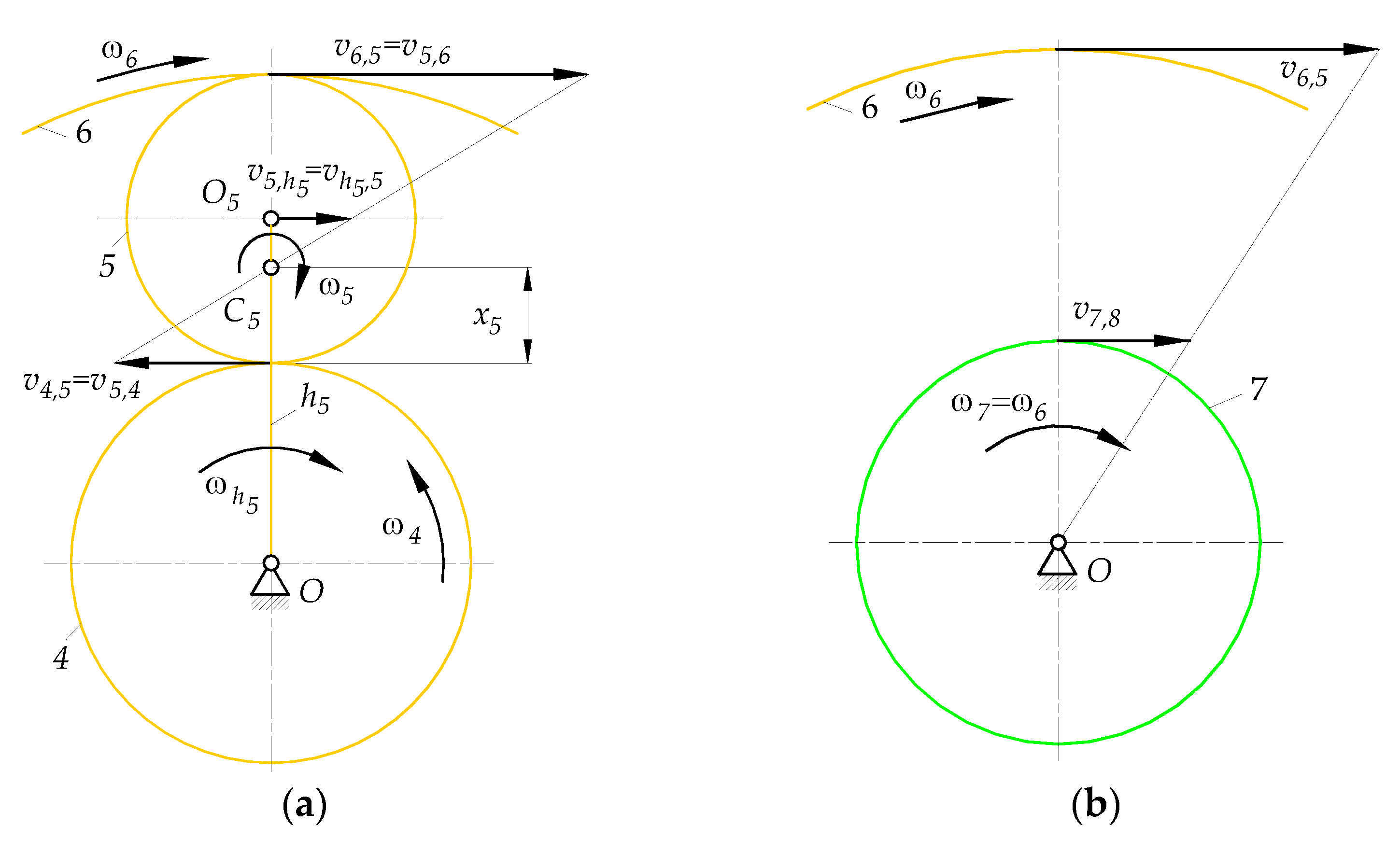
- Angular velocity of the planet gear 5 (check (A14)):
- Tangential velocities and of the centre of the planet gear 5 and the carrier , respectively (Figure B2(a)):
- Angular velocity of carrier (Figure B2(a)):
- Tangential velocity of the sun gear 7 at the point of contact with the planet gears 8 (Figure B2(b)):
B.4. Determination of instantaneous centre of zero velocity and velocities of the carrier
- The coordinate of the instantaneous centre of zero velocity of the planet gear 8 (Figure B3):
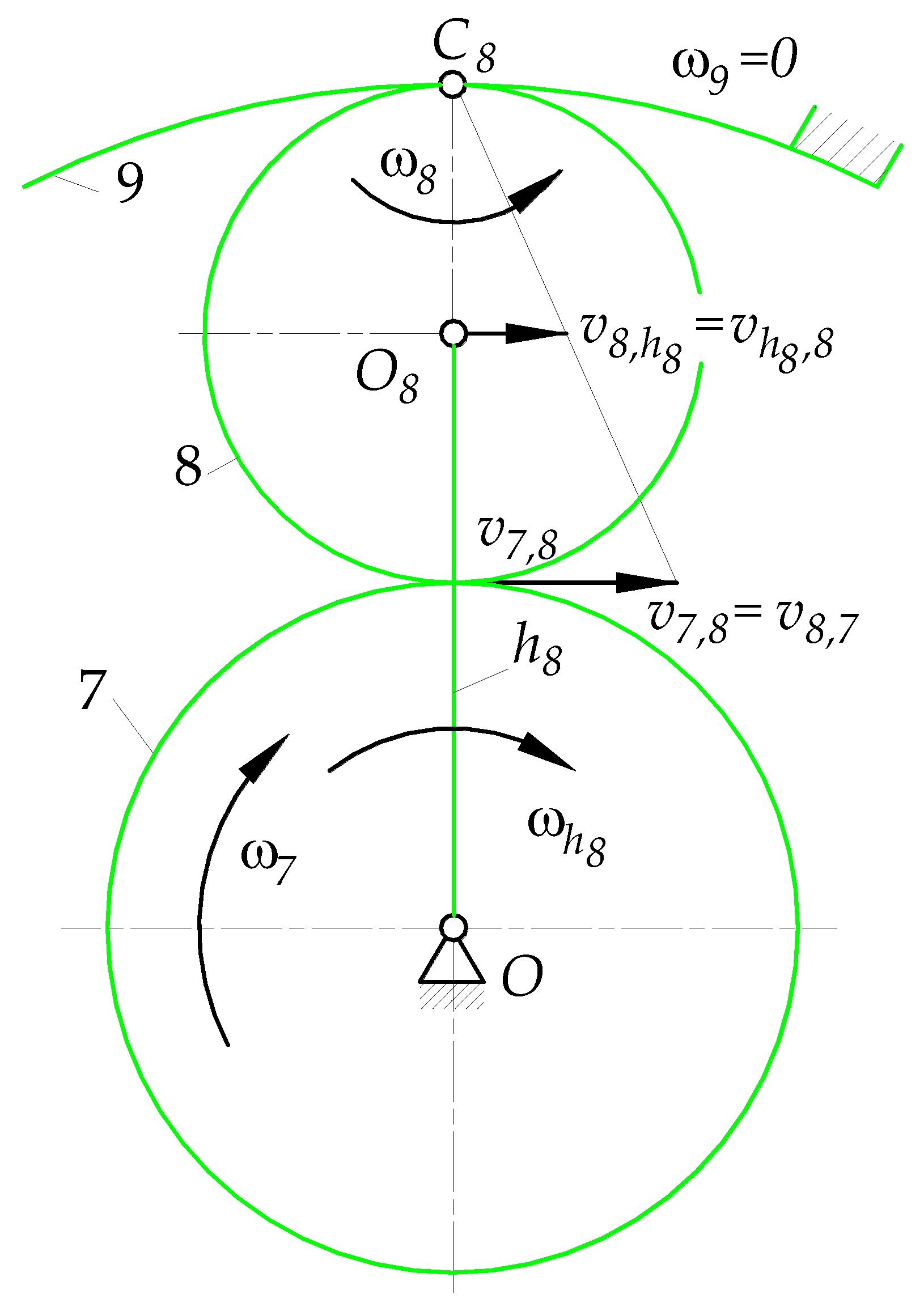
- Angular velocity of the planet gear 8 (check (A15)):
- Magnitude of velocities and , respectively, of the center of the planet gear 8 and the carrier (Figure B3):
- Angular velocity of the carrier (Figure B3):
| 0.007 | 0.014 | 0.024 |
Appendix C
C.1. Calculation of torques, tangential and radial forces acting on gears 1, 2, 3 and carrier
- The tangential force exerted by the planet gear 2 on the sun gear 1 (Figure C1(a)):
- The radial force exerted by the planet gear 2 on sun gear 1:
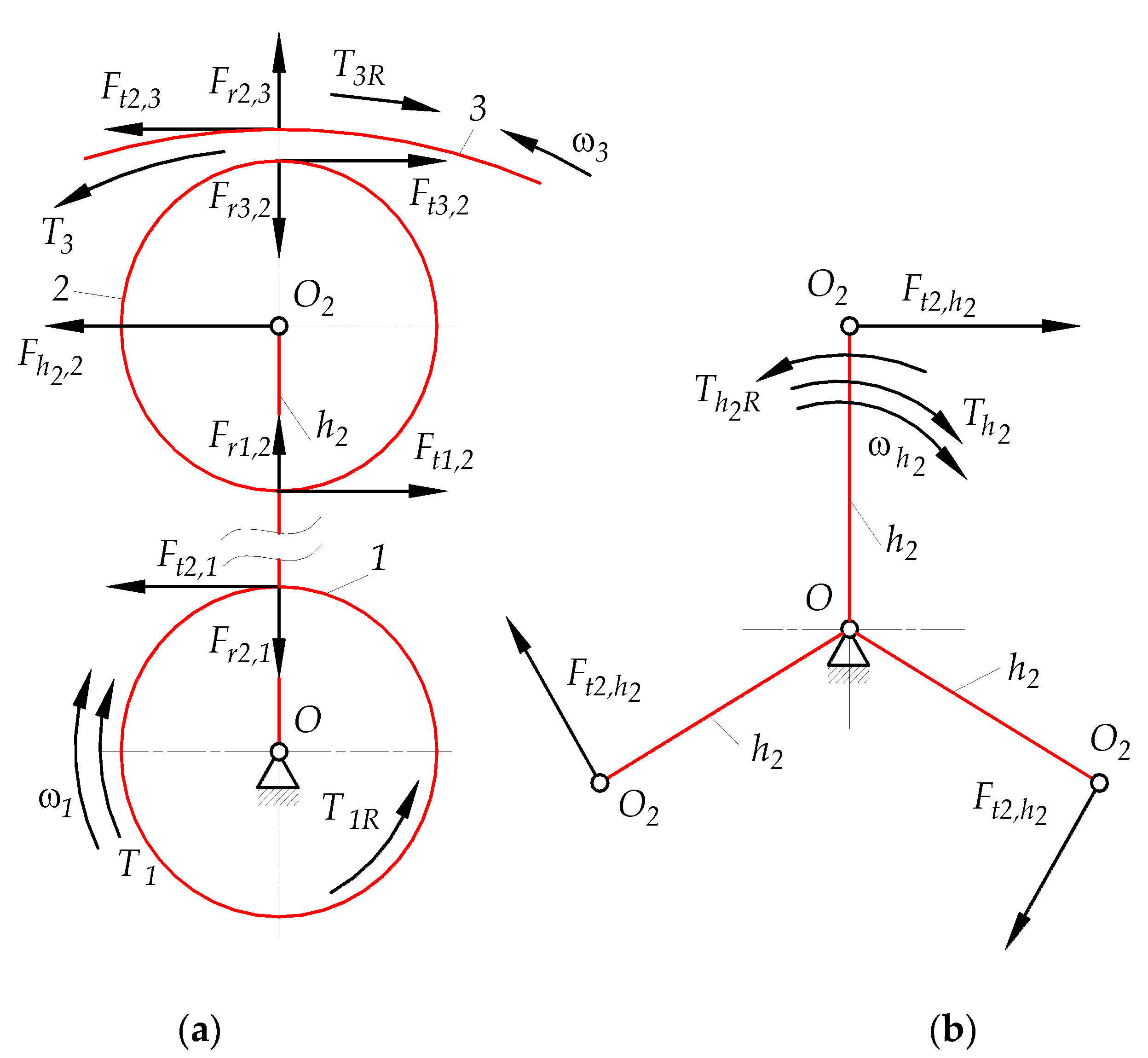
- The tangential force exerted by the sun gear 1 on the planet gear 2:
- The radial force exerted by the sun gear 1 on the planet gear 2:
- The tangential force exerted by the ring gear 3 on the planet gear 2:
- The tangential force exerted by the planet gear 2 on the ring gear 3:
- The radial forces and exerted respectively by the planet gear 2 on the ring gear 3 and vice versa by the ring gear 3 on the planet gear 2:
- The force exerted by the carrier on the center of planet gear 2 (Figure C1(b)):
- The tangential force exerted by the center of planet gear 2 on the carrier :
- The active torque transmitted to the shaft of the working machine II through the shaft of carrier :
- The reaction torque (generated by the resistance of the working machine) balancing the active torque :
- The active torque transmitted to the shaft of sun gear 4 through the shaft of ring gear 3):
- The reaction torque (generated by the resistance of subsystem B) balancing the active torque :
C.2. Calculation of torques, tangential and radial forces acting on gears 4, 5, 6 and carrier

- The reaction torque balancing the active torque :
- The tangential force F exerted by the planet gear 5 on the sun gear 4 (Figure C3(a)):
- The tangential force exerted by the sun gear 4 on the planet gear 5:
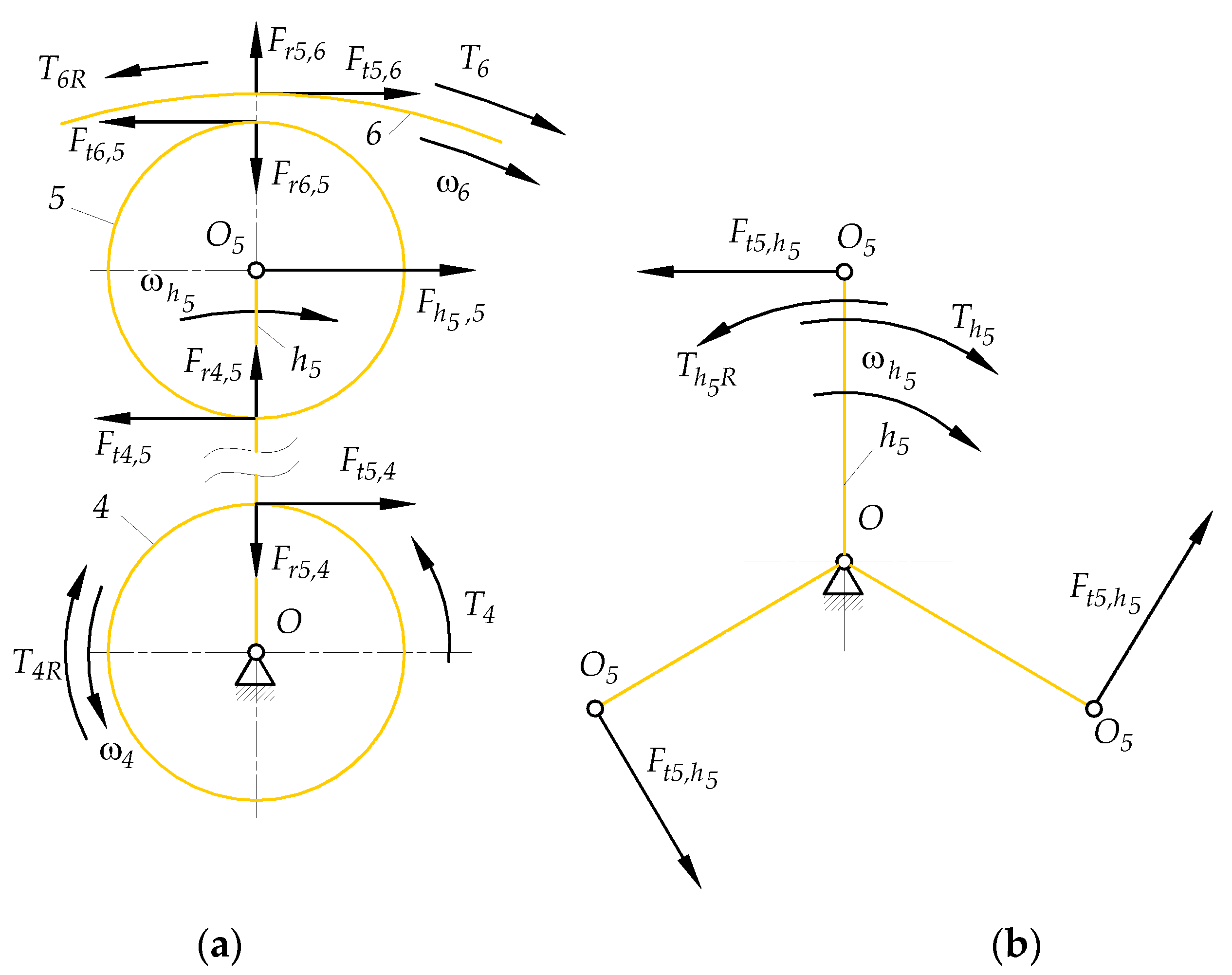
- The radial forces and exerted respectively by the planet gear 5 on the sun gear 4 and vice versa by the sun gear 4 on the planet gear 5 (Figure C3(a)):
- The tangential force exerted by the ring gear 6 on the planet gear 5:
- The tangential force exerted by the planet gear 5 on the ring gear 6:
- The radial forces and exerted respectively by the planet gear 5 on the ring gear 6 and vice versa by the ring gear 6 on the planet gear 5 (Figure C3(a)):
- The force exerted by the carrier on the center of planet gear 5 (Figure C3(b)):
- The tangential force exerted by the center of planet gear 5 on the carrier :
- The active torque driving the shaft of carrier and carrier according to Figure C3(b):
- The reaction torque balancing the active torque :
- The active torque driving the shaft of sun gear 7 through the shaft of ring gear 6 (Figure C4):
- The reaction torque balancing the active torque :
C.3. Calculation of torques, tangential and radial loads acting on gears 7,8, 9 and carrier
- The reaction torque balancing the active torque (Figure C4):
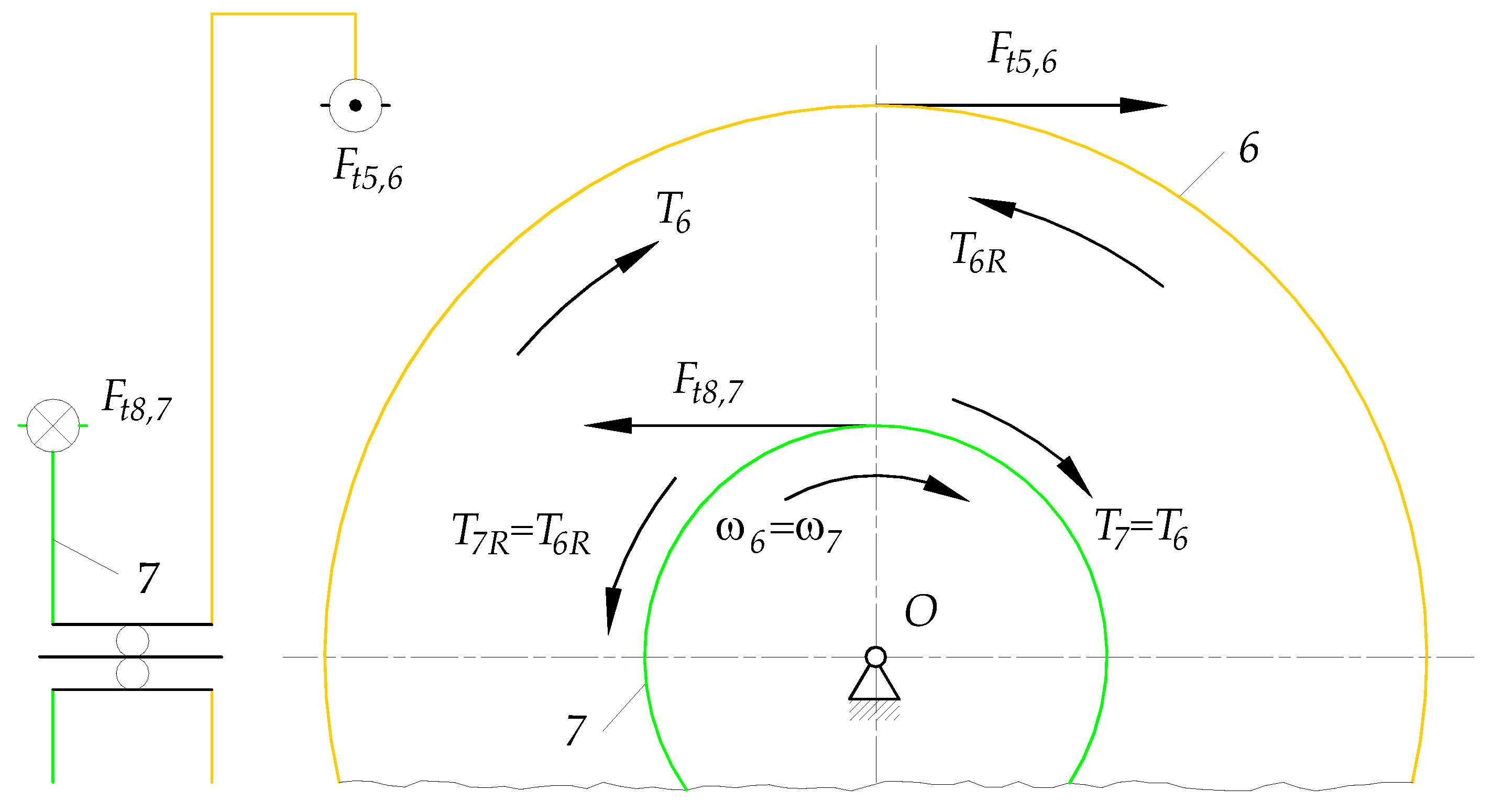
- The active torque driving the shaft of sun gear 7 (Figure C4):
- The tangential force exerted by the planet gear 8 on the sun gear 7 according to Figure C5(a):
- The tangential force exerted by the sun gear 7 on the planet gear 8:
- The radial forces and exerted respectively by the planet gear 8 on the sun gear 7 and vice versa by the sun gear 7 on the planet gear 8 (Figure C5(a)):
- The tangential force exerted by the ring gear 9 on the planet gear 8:
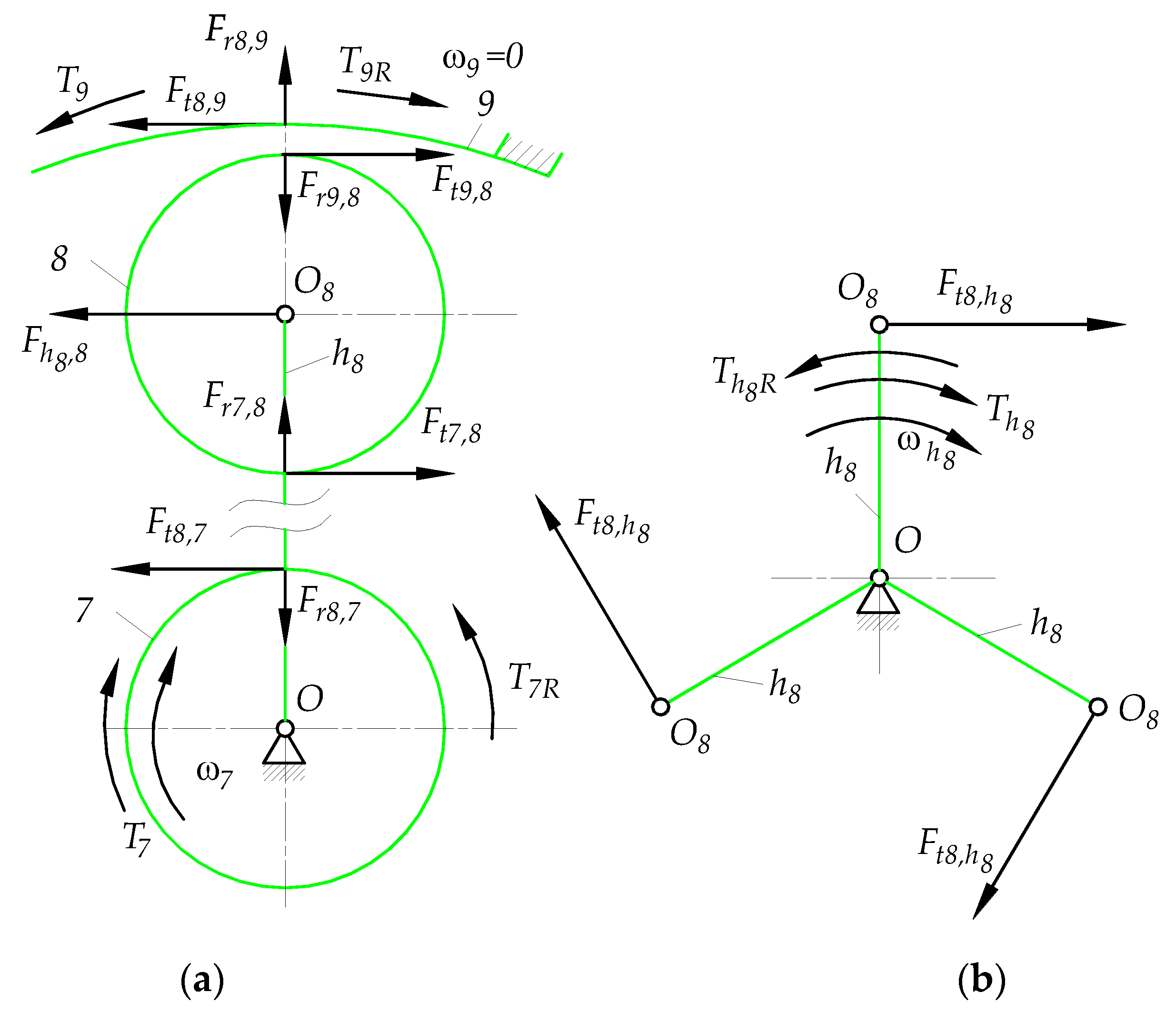
- The tangential force exerted by the planet gear 8 on the ring gear 9:
- The radial forces and exerted respectively by the ring gear 9 on the planet gear 8 and vice versa by the planet gear 8 on the ring gear 9 (Figure C5(a)):
- The active torque loading the fixed ring gear 9:
- The reaction torque balancing the active torque :
- The force exerted by the carrier on the center of planet gear 8 (Figure C5(a)):
- The tangential force exerted by the center of planet gear 8 on the carrier (Figure C5(b)):
- The active torque driving the shaft of carrier :
- The reaction torque balancing the active torque :
Appendix D
D.1. Calculations of powers and power ratios of subsystem A
- Power transmitted to subsystem A by the shaft I of sun gear 1 ():
- Power transmitted outside subsystem A by the shaft of ring gear 3 ():
- Power transmitted outside subsystem A by the shaft of carrier ():
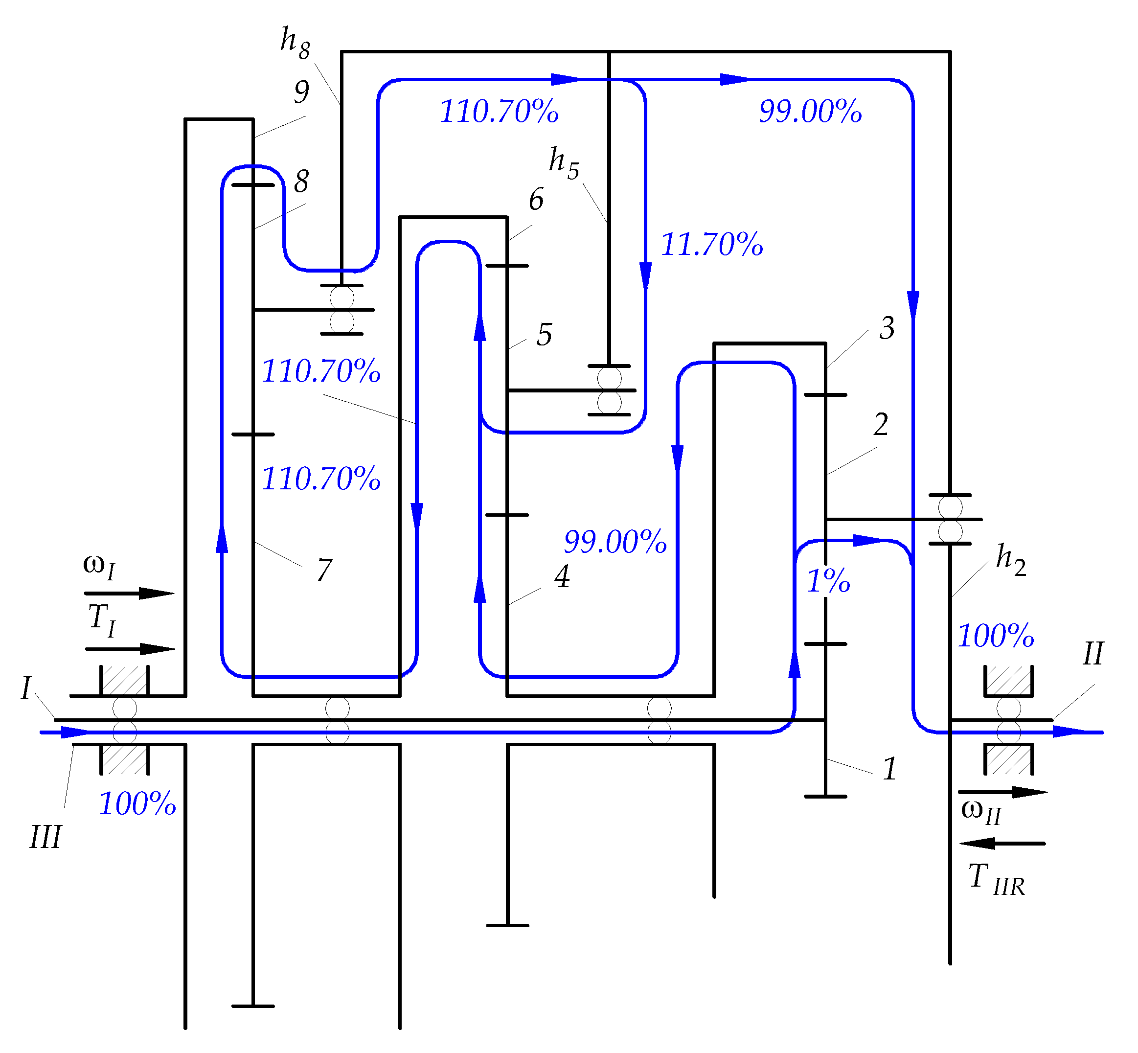
- Power ratio in the power flow path from the input shaft to the shaft of carrier (Figure 9):
- Power ratio in the power flow path from the input shaft I to the shaft of ring gear 3 (Figure 9):
- Power ratio in the power flow paths from the input shaft I to the shafts of carrier and rim gear 3 (checking the absence of the power losses in subsystem A):
D.2. Calculations of powers and power ratios of subsystem B
- Power transferred to subsystem B by the shaft of sun gear 4:
- Power transmitted to subsystem B by the shaft of carrier :
- Power transmitted outside subsystem B by the shaft of ring gear 6:
- Power ratio in the power flow path from the shaft of rim gear 3 to the shaft of sun gear 4 i.e. from subsystem A to subsystem B (Figure 9):
- Power ratio in the power flow path from the shaft of carrier to subsystem B due to the coupling phenomenon (Figure 9):
- Power ratio in the power flow path from the shaft of rim gear 6 to the shaft of sun gear 7 i.e. from subsystem B to subsystem C (Figure 9):
- Power ratio in the power flow paths from the shafts of sun gear 4 and carrier to the shaft of rim gear 6 (checking for no power loss in subsystem B):
D.3. Calculations of powers and power ratios of subsystem C
- Power transmitted to subsystem C by the shaft of sun gear 7:
- Power transmitted to the fixed shaft of ring gear 9 ():
- Power transmitted to the outside of the subsystem C by the shaft of carrier :
- Power ratio in the power flow path from the shaft of rim gear 6 to the shaft of sun gear 7 i.e. from subsystem B to subsystem C (Figure 9):
- Power ratio in the power flow path from the shaft of sun gear 7 to the shaft of carrier (Figure 9):
- Power ratio in the power flow path along the shaft of carrier from connection point with the carriers shafts and before connection point with the carrier (Figure 9):
- Power transmitted by the output shaft II of the PGS:
- Power ratio in the power flow paths between input shaft I and output shaft II (confirmation of no power loss):
- The efficiency of the PGS (confirmation of no power loss):
- Torque acting on the output shaft II:
- Total gear ratio (for ):
References
- Davies, T. An extension of Manolescu’s classification of planar kinematic chains and mechanisms of mobility M ≥ 1, using graph theory. J. Mech. 1968, 3, 87–100. [Google Scholar] [CrossRef]
- Gogu, G. Mobility of mechanisms: A critical review. Mech. Mach. Theory 2005, 40, 1068–1097. [Google Scholar] [CrossRef]
- Gogu, G. Chebychev–Grübler–Kutzbach’s criterion for mobility calculation of multi-loop mechanisms revisited via theory of linear transformations. Eur. J. Mech. 2005, 24, 427–441. [Google Scholar] [CrossRef]
- Liberati, A.; Belfiore, N.P. A method for the identification of the connectivity in multi-loop kinematic chains: Analysis of chains with total and partial mobility. Mech. Mach. Theory 2006, 41, 1443–1466. [Google Scholar] [CrossRef]
- Huang, Z.; Liu, J.; Li, Q. A Unified Methodology for Mobility Analysis Based on Screw Theory. In Smart Devices and Machines for Advanced Manufacturing; Wang, L., Xi, J., Eds.; Springer: London, UK, 2008; pp. 49–76. [Google Scholar]
- Zhua, X.; Shena, H.; Wua, C.; Chablat, D.; Yang, T. Computer-aided mobility analysis of parallel mechanisms. Mech. Mach. Theory 2020, 148, 103810. [Google Scholar] [CrossRef]
- Laughlin, H.; Holowenko, A.; Hall, A. How to determine circulating power in controlled epicyclic gear systems. Mach. Des. 1956, 28, 132–136. [Google Scholar]
- Gupta, A.K.; Ramanarayanan, C.P. Analysis of circulating power within hybrid electric vehicle transmissions. Mech. Mach. Theory 2013, 64, 131–143. [Google Scholar] [CrossRef]
- Bottiglione, F.; De Pinto, S.; Mantriota, G. Infinitely Variable Transmissions in neutral gear: Torque ratio and power recirculation. Mech. Mach. Theory 2014, 74, 285–298. [Google Scholar] [CrossRef]
- Hussen, H.A.; Hussain, R.A.; Esmail, E.L. A Simplified Algorithm for Detecting Power Recirculation within 1-Dof Multi-Entity Planetary Gear Trains. In Proceedings of the 3rd International Conference on Sustainable Engineering Techniques, Baghdad, Iraq, 15 April 2020; IOP Conference Series: Materials Science and Engineering. IOP Publishing: Bristol, UK, 2020; Volume 881, p. 012087. [Google Scholar] [CrossRef]
- Chen, H.; Chen, X.-A. Recirculation of Parallel-Connected Planetary Gear Trains. Chin. J. Mech. Eng. 2022, 35, 27. [Google Scholar] [CrossRef]
- Buckingham, E.N. (Ed.) Spur Gears; McGraw-Hill: New York; pp. 259–261.
- Brandenberger, H. (Ed.) Wirkungsgrad und Aufbau einfacher und zusammengesetzter Umlaufraedergetriebe. In Maschinenbau Betrieb; 1929, 8 u. 9); pp. 249/253 u. 290/294.
- Rudenko, N.F. Planetary Gears, 3rd ed.; Mashgiz 1947, 3rd Edition. (In Russian)
- Müller, L.; Wilk, A. Planetary Gears; PWN: Warsaw, Poland, 1996. (In Polish) [Google Scholar]
- Arnaudov, K.; Karaivanov, D.P. Planetary Gear Trains; CRC Press: London, UK; Taylor & Francis Group: New York, NY, USA, 2019. [Google Scholar]
- Krukowski, A. Fundamentals of planetary gear theory. In Machine Design Basics; Dietrich, M., Ed.; PWN: Warsaw, Poland, 1991; Volume 4, pp. 330–360. (In Polish) [Google Scholar]
- Radzimovsky, E.I. A Simplified Approach for Determining Power Losses and Efficiency of Planetary Gear Drives. Mach. Des. 1956, 28, 101–110. [Google Scholar]
- Radzimovsky, E.I. How to find efficiency, speed and power losses in planetary gear drives. Mach. Des. 1959, 31, 144–153. [Google Scholar]
- Macmillan, R.H. Power flow and loss in differential mechanisms. J. Mech. Eng. Sci. 1961, 3, 37–41. [Google Scholar] [CrossRef]
- Sanger, D. The determination of power flow in multiple-path transmission systems. Mech. Mach. Theory 1972, 7, 103–109. [Google Scholar] [CrossRef]
- Salgado, D.R.; Del Castillo, J.M. Selection and Design of Planetary Gear Trains Based on Power Flow Maps. J. Mech. Des. 2005, 127, 120–134. [Google Scholar] [CrossRef]
- Bu, Z.; Liu, G.; Wu, L.; Liu, Z. Kinematics and Statics Analysis for Power Flow Planet Gear Trains. In Global Design to Gain a Competitive Edge; Yan, X.-T., Eynard., B., Ion, W.J., Eds.; Springer: London, UK, 2008; pp. 631–640. [Google Scholar]
- Dooner, D.; Yoon, H.-D.; Seireg, A. Kinematic considerations for reducing the circulating power effects in gear-type continuously variable transmissions. Proc. IMechE Part D J. Automob. Eng. 1998, 212, 436–478. [Google Scholar] [CrossRef]
- Hedman, A. Transmission Analysis—Automatic Derivation of Relationships. J. Mech. Des. 1993, 115, 1031–1037. [Google Scholar] [CrossRef]
- Rabindran, D.; Tesar, D. ParametricDesign and Power-Flow Analysis of Parallel Force/Velocity Actuators. J. Mech. Robot. 2009, 1, 011007-1. [Google Scholar] [CrossRef]
- Rabindran, D.; Tesar, D. ParametricDesign of Parallel Force/Velocity Actuators: Force Distribution Analysis. J. Mech. Robot. 2010, 2, 011013-1. [Google Scholar] [CrossRef]
- Wang, C.; Cui, H.-Y. The analysis of power circulation and the simplified expression of the transmission efficiency of 2K-H closed epicyclic gear trains. Meccanica 2013, 48, 1071–1080. [Google Scholar] [CrossRef]
- Arnaudov, K.; Karaivanov, D. Alternative Method for Analysis of Complex Compound Planetary Gear Trains: Essence and Possibilities. In Power Transmissions, Mechanisms and Machine Science 13; Dobre, G., Ed.; Springer Science & Business Media: Dordrecht, The Netherlands, 2013. [Google Scholar] [CrossRef]
- Li, J.; Hu, Q. Power analysis and efficiency calculation of the complex and closed planetary gears transmission. Energy Procedia 2016, 100, 423–433. [Google Scholar]
- Nutakor, C.; Kłodowski, A.; Sopanen, J.; Mikkola, A.; Pedrero, J.I. Planetary gear sets power loss modeling: Application to wind turbines. Tribol. Int. 2017, 105, 42–54. [Google Scholar] [CrossRef]
- Theochari, G.; Troha, S.; Karaivanov, D. Reducer with a planetary gear train for a hoisting mechanism of dangerous goods cranes. Int. Scient. J. “Trans Motauto World” 2020, 5, 125–128. [Google Scholar]
- Hussen, H.A.; Essam Lauibi Esmail, E.L.; Hussen, R.A. Power Flow Simulation for Two-Degree-of-Freedom Planetary Gear Transmissions with Experimental Validation. Hindawi Model. Simul. Eng. 2020, 2020, 8837605. [Google Scholar] [CrossRef]
- Sun, Z.; Gao, B.; Jin, J.; Sanada, K. Power Loss Evaluation of Automated Manual Transmission with Gearshift Assistant Mechanism. Int. J. Automot. Technol. 2021, 22, 441–454. [Google Scholar] [CrossRef]
- Kahraman, A.; Ligata, H.; Kienzle, K.; Zini, D.M. A Kinematics and Power Flow Analysis Methodology for Automatic Transmission Planetary Gear Trains. J. Mech. Des. 2004, 126, 1071–1081. [Google Scholar] [CrossRef]
- Dong, P.; Liu, Y.; Tenberge, P.; Xu, X. Design and analysis of a novel multi-speed automatic transmission with four degrees-of-freedom. Mech. Mach. Theory 2017, 108, 83–96. [Google Scholar] [CrossRef]
- Liu, J.; Yu, L.; Zeng, Q.; Li, Q. Synthesis of multi-row and multi-speed planetary gear mechanism for automatic transmission. Mech. Mach. Theory 2018, 128, 616–627. [Google Scholar] [CrossRef]
- Hwang, W.-M.; Huang, Y.-L. Connecting clutch elements to planetary gear trains for automotive automatic transmissions via coded sketches. Mech. Mach. Theory 2011, 46, 44–52. [Google Scholar] [CrossRef]
- Ciobotaru, T.; Frunzeti, D.; Rus, I.; Jantschi, L. Method for analyzing multi-path power flow transmissions. Proc. IMechE Part B J. Eng. Manuf. 2009, 224, 1447–1454. [Google Scholar] [CrossRef]
- Chen, H.; Chen, X.A. New Methodology for Multistage Multispeed Planetary Transmission Design Based on Geometry. J. Mech. Des. 2021, 143, 113401. [Google Scholar] [CrossRef]
- Zhang, Q.; Liu, X. Optimization of the Quality of the Automatic Transmission Shift and the Power transmission Characteristics. Energies 2022, 15, 4672. [Google Scholar] [CrossRef]
- Zhang, W.; Yang, J.; Zhang, W. Influence of a New Type of Two-Speed Planetary Gear Automatic Transmission on the Performance of Battery Electric Vehicles. Energies 2022, 15, 4162. [Google Scholar] [CrossRef]
- Mangialardi, L.; Mantriota, G. The advantages of using continuously variable transmission in wind power systems. Renew. Energy 1992, 2, 201–209. [Google Scholar] [CrossRef]
- Mangialardi, L.; Mantriota, G. Power flows and efficiency in infinitely variable transmissions. Mech. Mach. Theory 1999, 34, 973–994. [Google Scholar] [CrossRef]
- Mantriota, G. Theoretical and experimental study of power split CVT systems: Part I. Proc. IMechE Part D J. Automob. Eng. 2001, 215, 837–850. [Google Scholar] [CrossRef]
- Mantriota, G. Theoretical and experimental study of power split CVT systems: Part II. Proc. IMechE Part D J. Automob. Eng. 2001, 215, 851–864. [Google Scholar] [CrossRef]
- Mucino, V.H.; Lu, Z.; Smith, J.E.; Kimcikiewicz, M.; Cowan, B. Design of continuously variable power split transmission systems for automotive applications. Proc. IMechE Part D J. Automob. Eng. 2001, 215, 469–478. [Google Scholar] [CrossRef]
- Mantriota, G. Performances of a series infinitely variable transmission with type I power flow. Mech. Mach. Theory 2002, 37, 579–597. [Google Scholar] [CrossRef]
- Mantriota, G. Performances of a parallel infinitely variable transmissions with a type II power flow. Mech. Mach. Theory 2002, 37, 555–578. [Google Scholar] [CrossRef]
- Zhao, X.; Maißer, P. A novel power splitting drive train for variable speed wind power generators. Renew. Energy 2003, 28, 2001–2011. [Google Scholar] [CrossRef]
- Linares, P.; Méndez, V.; Catalán, H. Design parameters for continuously variable power-split transmissions using planetaries with 3 active shafts. J. Terramechanics 2010, 47, 323–335. [Google Scholar] [CrossRef]
- Macor, A.; Rossett, A. Optimization of hydro-mechanical power split transmissions. Mech. Mach. Theory 2011, 46, 1901–1919. [Google Scholar] [CrossRef]
- Bottiglione, F.; Mantriota, G. Power Flows and Efficiency of Output Compound e-CVT. Intern. J. Veh. Des. 2015, 2015, 136437. [Google Scholar] [CrossRef]
- Mantriota, G. Power split transmissions for wind energy systems. Mech. Mach. Theory 2017, 117, 160–174. [Google Scholar] [CrossRef]
- Ismaeil, E.L. Comments on “Power flow and efficiency analysis of epicyclic gear transmission with split power”. Mech. Mach. Theory 2017, 115, 237–243. [Google Scholar]
- Esmail, E.L. Comments on “Analysis of circulating power within hybrid electric vehicle transmissions”, Mechanism and Machine Theory 64 (2013) 131–143, by A.K. Gupta, C.P. Ramanarayanan. Mech. Mach. Theory 2018, 121, 425–429. [Google Scholar] [CrossRef]
- Cammalleri, M.; Rotella, D. Functional design of power-split CVTs: An uncoupled hierarchical optimized model. Mech. Mach. Theory 2017, 116, 294–309. [Google Scholar] [CrossRef]
- Rotella, D.; Cammalleri, M. Direct analysis of power-split CVTs: A unified method. Mech. Mach. Theory 2018, 121, 116–127. [Google Scholar] [CrossRef]
- Rotella, D.; Cammalleri, M. Power losses in power-split CVTs: A fast black-box approximate method. Mech. Mach. Theory 2018, 128, 528–543. [Google Scholar] [CrossRef]
- Xiong, S.; Wilfong, G.; Lumkes, J., Jr. Components Sizing and Performance Analysis of Hydro-Mechanical Power Split Transmission Applied to a Wheel Loader. Energies 2019, 12, 1613. [Google Scholar] [CrossRef]
- Wang, G.; Song, Y.; Wang, J.; Wanqiang Chen, W.; Cao, Y.; Wang, J. Study on the Shifting Quality of the CVT Tractor under Hydraulic System Failure. Appl. Sci. 2020, 10, 681. [Google Scholar] [CrossRef]
- Neagoe, M.; Saulescu, R.; Jaliu, C.; Simionescu, P.A. A Generalized Approach to the Steady-State Efficiency Analysis of Torque-Adding Transmissions Used in Renewable Energy Systems. Energies 2020, 13, 4568. [Google Scholar] [CrossRef]
- Lin, A.-D.; Hung, T.-D.; Kuang, J.-H.; Tsai, H.-A. Power Flow Analysis on the Dual Input Transmission Mechanism of Small Wind Turbine Systems. Appl. Sci. 2020, 10, 7333. [Google Scholar] [CrossRef]
- Mantriota, G.; Reina, G.; Ugenti, A. Performance Evaluation of a Compound Power-Split CVT for Hybrid Powertrains. Appl. Sci. 2021, 11, 8749. [Google Scholar] [CrossRef]
- Li, Q.; Zhang, Z.; Bai, J.; Zhang, T.; Gai, F. Development of compound power-split hybrid power system for commercial vehicles. Int. J. Automot. Technol. 2022, 23, 135–147. [Google Scholar] [CrossRef]
- Li, X.; Kang, X.; Ba, X.; Peng, Z.; Yang, S.; Zhao, Z. A Design Methodology for Dual-Mode Electro-Mechanical Transmission Scheme Based on Jointing Characteristics. Energies 2022, 15, 5482. [Google Scholar] [CrossRef]
- Kukla, M.; Wieczorek, B.; Warguła, Ł.; Rybarczyk, D.; Górecki, J. Manual Wheelchair Equipped with a Planetary Gear-Research Methodology and Preliminary Results. Appl. Sci. 2022, 12, 7737. [Google Scholar] [CrossRef]
- Wang, L.; Cui, Y.; Zhang, F.; Li, G. Architectures of Planetary Hybrid Powertrain System: Review, Classification and Comparison. Energies 2020, 13, 329. [Google Scholar] [CrossRef]
- Ngo, H.-T.; Yan, H.-S. Configuration synthesis of parallel hybrid transmissions. Mech. Mach. Theory 2016, 97, 51–71. [Google Scholar] [CrossRef]
- Yang, F.; Feng, J.; Du, F. Design and Power Flow Analysis for Multi-Speed Automatic Transmission with Hybrid Gear Trains. Int. J. Automot. Technol. 2016, 17, 629–637. [Google Scholar] [CrossRef]
- Ahn, K.; Cho, S.-T.; Lim, W.; Park, Y.-I.; Lee, J.M. Performance analysis and parametric design of the dual-mode planetary gear hybrid powertrain. Proc. IMechE Part D J. Automob. Eng. 2006, 220, 1601–1614. [Google Scholar] [CrossRef]
- Kim, N.; Kim, J.; Kim, H. Control of Dual Mode Power Split Transmission for a Hybrid Electric Vehicle. World Electr. Veh. J. 2008, 2, 353–362. [Google Scholar] [CrossRef]
- Cammalleri, M.; Castellano, A. Analysis of hybrid vehicle transmissions with any number of modes and planetary gearing: Kinematics, power flows, mechanical power losses. Mech. Mach. Theory 2021, 162, 104350. [Google Scholar] [CrossRef]
- Li, Q.; Zhang, Z.; Zhang, T.; Guo, H. Control optimization of a compound power-split hybrid power system for commercial vehicles. Proc. IMechE Part D J. Automob. Eng. 2021, 235, 2509–2524. [Google Scholar] [CrossRef]
- Van Harselaar, W.; Brouwer, M.; Hofman, T. A generic transmission model for hybrid electric drives. Forsch. Ingenieurwes. 2019, 83, 1–9. [Google Scholar] [CrossRef]
- Yang, F.; Feng, J.; Zhang, H. Power flow and efficiency analysis of multi-flow planetary gear trains. Mech. Mach. Theory 2015, 92, 86–99. [Google Scholar] [CrossRef]
- Yin, C.; Tang, D.; Deng, Z. Research on configurations of multi-axis speed-differential mechanisms based on 2K-H gear train. Mech. Mach. Theory 2020, 148, 103783. [Google Scholar] [CrossRef]
- Gu, J.; Zhao, Z.; Chen, Y.; He, L.; Zhan, X. Integrated optimal design of configuration and parameter of multimode hybrid powertrain system with two planetary gears. Mech. Mach. Theory 2020, 143, 103630. [Google Scholar] [CrossRef]
- Kim, H.; Wi, J.; Yoo, J.; Son, H.; Park, C.; Kim, H. A Study on the Fuel Economy Potential of Parallel and Power Split Type Hybrid Electric Vehicles. Energies 2018, 11, 2103. [Google Scholar] [CrossRef]
- De Carlo, M.; Mantriota, G. Electric vehicles with two motors combined via planetary gear train. Mech. Mach. Theory 2020, 148, 103789. [Google Scholar] [CrossRef]
- Mantriota, G.; Reina, G. Dual-Motor Planetary Transmission to Improve Efficiency in Electric Vehicles. Machines 2021, 9, 58. [Google Scholar] [CrossRef]
- Cipek, M.; Pavkovic’, D.; Petric, J. A control-oriented simulation model of a power-split hybrid electric vehicle. Appl. Energy 2013, 101, 121–133. [Google Scholar] [CrossRef]
- Son, H.; Kim, H. Development of Near Optimal Rule-Based Control for Plug-In Hybrid Electric Vehicles Taking into Account Drivetrain Component Losses. Energies 2016, 9, 420. [Google Scholar] [CrossRef]
- Yang, W.; Liang, J.; Yang, J.; Zhang, N. Investigation of a Novel Coaxial Power-Split Hybrid Powertrain for Mining Trucks. Energies 2018, 11, 172. [Google Scholar] [CrossRef]
- Kim, S.J.; Kim, K.-S. Experimental Investigation of the Seamless Gearshift Mechanism Using an Electric Motor and a Planetary Gear-Set. Energies 2020, 13, 6705. [Google Scholar] [CrossRef]
- Kim, J.; Kang, J.; Kim, Y.; Kim, T.; Min, B.; Kim, H. Design of Power Split Transmission: Design of Dual Mode Power Split Transmission. Int. J. Automot. Technol. 2010, 11, 565–571. [Google Scholar] [CrossRef]
- Wang, W.; Song, S.; Guo, M.; Liu, S. Analysis on compound-split configuration of power-split hybrid electric vehicle. Mech. Mach. Theory 2014, 78, 272–288. [Google Scholar] [CrossRef]
- Esmail, E.L. Hybrid Transmission for Mobile Robot. J. Mech. Des. 2012, 134, 021001. [Google Scholar] [CrossRef]
- Ho, T.T.; Hwang, S.J. Configuration synthesis of two-mode hybrid transmission systems with nine-link mechanisms. Mech. Mach. Theory 2019, 142, 103615. [Google Scholar] [CrossRef]
- Li, H.; Hu, X.; Fu, B.; Wang, J.; Zhang, F.; Zhou, Y. Effective optimal control strategy for hybrid electric vehicle with continuously variable transmission. Adv. Mech. Eng. 2019, 11, 1–11. [Google Scholar] [CrossRef]
- Yang, H.; Chom, S.; Kim, N.; Lim, W.; Cha, S. Analysis of Planetary Gear Hybrid Powertrain System. Part 1: Input Split System. Intern. J. Automot. Technol. 2007, 8, 771–780. [Google Scholar]
- Yang, H.; Kim, N.; Par, Y.; Lim, W.; Cha, S. Analysis of Planetary Gear Hybrid Powertrain System. Part 2: Output Split System. Intern. J. Automot. Technol. 2009, 10, 381–390. [Google Scholar] [CrossRef]
- Schulz, M. Circulating mechanical power in a power-split hybrid electric vehicle transmission. Proc. IMech Part D J. Automob. Eng. 2004, 218, 1419–1425. [Google Scholar] [CrossRef]
- Kim, I.; Kim, H. Configuration Analysis of Plug-in Hybrid Systems using Global Optimization. World Electr. Veh. J. 2013, 6, 391–404. [Google Scholar] [CrossRef]
- Szumanowski, A.; Liu, Z.; Krawczyk, P. Analyse of Clutch-brake System Control Based on Experimental Tests and Applied in Hybrid Power Train. World Electr. Veh. J. 2013, 6, 353–363. [Google Scholar] [CrossRef]
- Zou, Y.; Huang, R.; Wu, X.; Zhang, B.; Zhang, Q.; Wang, N.; Qin, T. Modeling and energy management strategy research of a power-split hybrid electric vehicle. Adv. Mech. Eng. 2020, 12, 1–14. [Google Scholar] [CrossRef]
- De Pinto, S.; Mantriota, G. Power Flows in Compound Transmissions for Hybrid Vehicles. Machines 2019, 7, 19. [Google Scholar] [CrossRef]
- Mazali, I.I.; Daud, Z.H.C.; Hamid, M.K.A.; Tan, V.; Samin, P.M.; Jubair, A.; Ibrahim, K.A.; Kob, M.S.C.; Xinrui, W.; Talib, M.H.A. Review of the Methods to Optimize Power Flow in Electric Vehicle Powertrains for Efficiency and Driving Performance. Appl. Sci. 2022, 12, 1735. [Google Scholar] [CrossRef]
- Wang, S.; Li, J.; Shi, D.; Sun, X.; Yao, Y. Energy Management Strategy of Dual Planetary Hybrid Electric Vehicle Based on Optimal Transmission Efficiency. J. Theor. Appl. Mech. 2019, 57, 383–396. [Google Scholar] [CrossRef]
- Huang, K.; Xiang, C.; Ma, Y.; Wang, W.; Langari, R. Mode Shift Control for a Hybrid Heavy-Duty Vehicle with Power-Split Transmission. Energies 2017, 10, 177. [Google Scholar] [CrossRef]
- Li, L.; Yana, B.; Songa, J.; Zhanga, Y.; Jiang, G.; Li, L. Two-step optimal energy management strategy for single-shaft series-parallel powertrain. Mechatronics 2016, 36, 147–158. [Google Scholar]
- Zhang, D.; Chen, J.; Hsieh, J.; Rancourt, J.; Schmidt, M.R. Dynamic modelling and simulation of two-mode electric variable transmission. Proc. IMechE Part D J. Automob. Eng. 2001, 215, 1217–1223. [Google Scholar] [CrossRef]
- Yaohua, L.; Wang Ying, W.; Xuan, Z. Modelling and Simulation Study on a Series-parallel Hybrid Electric Vehicle. World Electr. Veh. J. 2015, 7, 133–141. [Google Scholar]
- Chen, H.; Li, L.; Küçükay, F. Study of Series-Parallel and Power-Split DHT for Hybrid Powertrains. Automot. Innov. 2021, 4, 23–33. [Google Scholar] [CrossRef]
- Weichao Zhuang, W.; Zhang, X.; Peng, H.; Wang, L. Simultaneous Optimization of Topology and Component Sizes for Double Planetary Gear Hybrid Powertrains. Energies 2016, 9, 411. [Google Scholar] [CrossRef]
- Wu, J.; Liang, J.; Ruan, J.; Zhang, N.; Walker, P.D. Efficiency comparison of electric vehicles powertrains with dual motor and single motor input. Mech. Mach. Theory 2018, 128, 569–585. [Google Scholar] [CrossRef]
- Liang, J.; Yang, H.; Wu, J.; Zhang, N.; Walker, P.D. Shifting and power sharing control of a novel dual input clutchless transmission for electric vehicles. Mech. Syst. Signal Process. 2018, 104, 725–743. [Google Scholar] [CrossRef]
- Tom Verstraten, T.; Furnémont, R.; López-García, P.; Rodriguez-Cianca, D.; Cao, H.-L.; Vanderborght, B.; Lefeber, D. Modeling and design of an energy-efficient dual-motor actuation unit with a planetary differential and holding brakes. Mechatronics 2018, 49, 134–148. [Google Scholar] [CrossRef]
- Han, J.-O.; Shin, J.-W.; Kim, J.-C.; Oh, S.-H. Design 2-Speed Transmission for Compact Electric Vehicle Using Dual Brake System. Appl. Sci. 2019, 9, 1793. [Google Scholar] [CrossRef]
- Hu, J.; Mei, B.; Peng, H.; Jiang, X. Optimization Design and Analysis for a Single Motor Hybrid Powertrain Configuration with Dual Planetary Gears. Appl. Sci. 2019, 9, 707. [Google Scholar] [CrossRef]
- Zhao, X.; Tang, J. Modeling and Optimal Shift Control of a Planetary Two-Speed Transmission. World Electr. Veh. J. 2019, 10, 53. [Google Scholar] [CrossRef]
- Nazari, S.; Siegel, J.; Middleton, R.; Stefanopoulou, A. Power Split Supercharging: A Mild Hybrid Approach to Boost Fuel Economy. Energies 2020, 13, 6580. [Google Scholar] [CrossRef]
- Tota, A.; Galvagno, E.; Dimauro, L.; Vigliani, A.; Velardocchia, M. Energy Management Strategy for Hybrid Multimode Powertrains: Influence of Inertial Properties and Road Inclination. Appl. Sci. 2021, 11, 11752. [Google Scholar] [CrossRef]
- Castellano, A.; Cammalleri, M. Power Losses Minimization for Optimal Operating Maps in Power-Split HEVs: A Case Study on the Chevrolet Volt. Appl. Sci. 2021, 11, 7779. [Google Scholar] [CrossRef]
- Yang, W.; Li, C. Symmetry Detection and Topological Synthesis of Mechanisms of Powertrains. Energies 2022, 15, 4755. [Google Scholar] [CrossRef]
- Chen, X.; Jiang, J.; Zheng, L.; Tang, H.; Chen, X. Study and Analysis of a Multi-Mode Power Split Hybrid Transmission. World Electr. Veh. J. 2020, 11, 46. [Google Scholar] [CrossRef]
- Dong, P.; Zuo, S.; Liu, T.; Xu, X.; Guo, W.; Liu, Y.; Wu, H.; Wang, S. A matrix-based method for searching configurations of planetary gear trains. Mech. Mach. Theory 2023, 180, 105161. [Google Scholar] [CrossRef]
- Benford, H.L.; Leising, M.B. The Lever Analogy: A New Tool in Transmission Analysis. SAE Trans. 1981, 90, 429–437. [Google Scholar] [CrossRef]
- Esmail, E.L.; Hussen, H. Nomographs for Kinematics, Statics and Power Flow Analysis of Epicyclic Gear Trains. In Proceedings of the 2009 ASME International Mechanical Engineering Congress and Exposition, Lake Buena Vista, FL, USA, 13–19 November 2009. [Google Scholar]
- Esmail, E.L.; Pennestrì, E.; Juber, A.H. Power Losses in Two-Degrees-of-Freedom Planetary Gear Trains: A Critical Analysis of Radzimovsky’s Formulas. Mech. Mach. Theory 2018, 128, 191–204. [Google Scholar] [CrossRef]
- Marciniec, A.; Sobolak, M.; Połowniak, P. Graphical method for the analysis of planetary gear trains. Alex. Eng. J. 2022, 61, 4067–4079. [Google Scholar] [CrossRef]
- Xie, T.; Hu, J.; Peng, Z.; Liu, C. Synthesis of seven-speed planetary gear trains for heavy-duty commercial vehicle. Mech. Mach. Theory 2015, 90, 230–239. [Google Scholar] [CrossRef]
- Zhang, Y.; Ma, X.; Yin, C.; Yuan, S. Development and Simulation of a Type of Four-Shaft ECVT for a Hybrid Electric Vehicle. Energies 2016, 9, 141. [Google Scholar] [CrossRef]
- Liao, Y.G.; Chen, M.-Y. Analysis of multi-speed transmission and electrically continuous variable transmission using lever analogy method for speed ratio determination. Adv. Mech. Eng. 2017, 9, 1–12. [Google Scholar] [CrossRef]
- Ho, T.-T.; Hwang, S.-J. Configuration Synthesis of Novel Hybrid Transmission Systems Using a Combination of a Ravigneaux Gear Train and a Simple Planetary Gear Train. Energies 2020, 13, 2333. [Google Scholar] [CrossRef]
- Yang, X.; Yu, W.; Shao, Y.; Xu, Z.; Zeng, Q.; Nie, C.; Peng, D. An Augmented Lever Analogy Method for Kinematic Analysis of Dual-Input Planetary/Epicyclic Gear Sets Involving Planet Gear. IEEE Access 2022, 10, 101137–101148. [Google Scholar] [CrossRef]
- Chen, X.-A.; Chen, H. Analytical geometry method of planetary gear trains. Sci. China Technol. Sci. 2012, 55, 1007–1021. [Google Scholar] [CrossRef]
- Esmail, E.L. Kinematic nomographs of epicyclic-type transmission mechanisms. Emir. J. Eng. Res. 2007, 12, 47–55. [Google Scholar]
- Esmail, E.L. Nomographs for synthesis of epicyclic-type automatic transmissions. Meccanica 2013, 48, 2037–2049. [Google Scholar] [CrossRef]
- Esmail, E.L. Nomographs and Feasibility Graphs for Enumeration of Ravigneaux-Type Automatic Transmissions. Adv. Mech. Eng. 2013, 5, 120324. [Google Scholar] [CrossRef]
- Del Castillo, J.M. The Analytical Expression of the Efficiency of Planetary Gear Trains. Mech. Mach. Theory 2002, 37, 197–214. [Google Scholar] [CrossRef]
- Chen, C.; Angeles, J. Virtual-power flow and mechanical gear-mesh power losses of epicyclic gear trains. J. Mech. Des. 2007, 129, 107–113. [Google Scholar] [CrossRef]
- Chen, C.; Liang, T.T. Theoretic Study of Efficiency of Two-DOFs of Epicyclic Gear Transmission via Virtual Power. J. Mech. Des. 2011, 133, 031007. [Google Scholar] [CrossRef]
- Chen, C. Power Analysis of Epicyclic Transmissions Based on Constraints. J. Mech. Robot. 2012, 4, 041004. [Google Scholar] [CrossRef]
- Chen, C. Power Flow and Efficiency Analysis of epicyclic gear transmission with split power. Mech. Mach. Theory 2013, 59, 96–106. [Google Scholar] [CrossRef]
- Chen, C.; Chen, J. Power analysis of two-dof epicyclic gear transmission and experimental validation. In Proceedings of the International Gear Conference, Lyon, France, 26–28 August 2014; pp. 646–658. [Google Scholar]
- Chen, C.; Chen, J. Efficiency analysis of two degrees of freedom epicyclic gear transmission and experimental validation. Mech. Mach. Theory 2015, 87, 115–130. [Google Scholar] [CrossRef]
- Wang, C. The effect of planetary gear/star gear on the transmission efficiency of closed differential double helical gear train. Proc. IMech Part C J. Mech. Eng. Sci. 2019, 233, 5647–5658. [Google Scholar] [CrossRef]
- Chen, C. Power Flow analysis of Compound Epicyclic Gear Transmission: Simpson Gear Train. J. Mech. Des. 2011, 133, 094502. [Google Scholar] [CrossRef]
- Li, J.; Wu, T.; Chi, W.; Hu, Q.; Meen, T. Integrated Analysis of Influence of Multiple Factors on Transmission Efficiency of Loader Drive Axle. Energies 2019, 12, 4540. [Google Scholar] [CrossRef]
- Esmail, E.L.; Pennestri, E.; Cirelli, M. Power-Flow and Mechanical Efficiency Computation in Two-Degrees-of-Freedom Planetary Gear Units: New Compact Formulas. Appl. Sci. 2021, 11, 5991. [Google Scholar] [CrossRef]
- Wojnarowski, J. Letters to the Editor Comments on “The Determination of Power Flow in Multiple-Path Transmission Systems”. Mech. Mach. Theory 1975, 10, 261–266. [Google Scholar] [CrossRef]
- Wojnarowski, J.; Lidwin, A. The application of signal flow graphs—The kinematic analysis of planetary gear trains. Mech. Mach. Theory 1975, 10, 17–31. [Google Scholar] [CrossRef]
- Wojnarowski, J. The Graph Method of Determining the Loads in Complex Gear Trains. Mech. Mach. Theory 1976, 11, 103–121. [Google Scholar] [CrossRef]
- Pennestri, E.; Freudenstein, F. A systematic approach to power-flow and static-force analysis in epicyclic spur-gear trains. J. Mech. Des. 1993, 115, 639–644. [Google Scholar] [CrossRef]
- Pennestri, E.; Freudenstein, F. The Mechanical Efficiency of Epicyclic Gear Trains. J. Mech. Des. 1993, 115, 645–651. [Google Scholar] [CrossRef]
- Valentini, P.P.; Pennestri, E. A Review of Formulas for the Mechanical Efficiency Analysis of Two Degrees-of-Freedom Epicyclic Gear Trains. J. Mech. Des. 2003, 125, 602–608. [Google Scholar] [CrossRef]
- Pennestri, E.; Mariti, L.; Valentini, P.P.; Mucino, V.H. Efficiency evaluation of gearboxes for parallel hybrid vehicles: Theory and applications. Mech. Mach. Theory 2012, 49, 157–176. [Google Scholar] [CrossRef]
- Del Pio, G.; Pennestri, E.; Valentini, P.P. Kinematic and power-flow analysis of bevel gears planetary gear trains with gyroscopic complexity. Mech. Mach. Theory 2013, 70, 523–537. [Google Scholar] [CrossRef]
- Geitner, G.-H.; Kömürgöz, G. Generic power split modelling for compound epicyclic four speed gears. Mech. Mach. Theory 2017, 116C, 50–68. [Google Scholar] [CrossRef]
- Geitner, G.-H.; Kömürgöz, G. Bond Graph Based Synthesis of Generic Power Split Modelling for Epicyclic Four-Speed Gears. In Graph-Based Modelling in Science, Technology and Art; Zawiślak, S., Rysiński, J., Eds.; Springer: Cham, Switzerland, 2022. [Google Scholar]
- Salgado, D.R.; del Castillo, J.M. Analysis of the transmission ratio and efficiency ranges of the four-, five-, and six-link planetary gear trains. Mech. Mach. Theory 2014, 73, 218–243. [Google Scholar] [CrossRef]
- Pennestrì, E.; Belfiore, N.P. On Crossley’s contribution to the development of graph based algorithms for the analysis of mechanisms and gear trains. Mech. Mach. Theory 2015, 89, 92–106. [Google Scholar] [CrossRef]
- Cui, Y.; Gao, J.; Ji, X.; Zhou, X.; Yan, H. The multi-attribute topological graph method and its application on power flow analysis in closed planetary gear trains. J. Adv. Mech. Eng. 2018, 10, 1–9. [Google Scholar] [CrossRef]
- Esmail, E.L.; Hassan, S.S. An approach to power-flow and static force analysis in multi-input multi-output epicyclic-type transmission trains. J. Mech. Des. 2010, 132, 0110091–01100910. [Google Scholar] [CrossRef]
- Ayats, J.R.G.; Calvet, J.V.; Canela, J.M.; Diego-Ayala, U.; Artes, F.F. Power transmitted through a particular branch in mechanisms comprising planetary gear trains and other fixed or variable transmissions. Mech. Mach. Theory 2011, 46, 1744–1754. [Google Scholar] [CrossRef]
- Ayats, J.R.G.; Diego-Ayala, U.; Artes, F.F. The singular point transition concept: A novel continuously variable transmission comprising planetary gear trains and a variator. J. Power Sources 2012, 197, 125–135. [Google Scholar] [CrossRef]
- Mantriota, G. Comments on “Power transmitted through a particular branch in mechanisms comprising planetary gear trains and other fixed or variable transmissions”. Mech. Mach. Theory 2014, 73, 101–102. [Google Scholar] [CrossRef]
- Xue, H.L.; Liu, G.; Yang, X.H. A review of graph theory application research in gears. Proc. IMechE Part C J. Mech. Eng. Sci. 2015, 30, 1697–1714. [Google Scholar] [CrossRef]
- Esmail, E.L. Meshing Efficiency Analysis of Two Degree-of-Freedom Epicyclic Gear Trains. J. Mech. Des. 2016, 138, 083301. [Google Scholar] [CrossRef]
- Wang, Y.; Yang, W.; Tang, X.; Lin, X.; He, Z. Power Flow and Efficiency Analysis of High-Speed Heavy Load Herringbone Planetary Transmission Using a Hypergraph-Based Method. Appl. Sci. 2020, 10, 5849. [Google Scholar] [CrossRef]
- Freudenstein, F.; Yang, A.T. Kinematics and Statics of Coupled Epicyclic Spur Gear Trains. Mech. Mach. Theory 1972, 7, 263–375. [Google Scholar] [CrossRef]
- Willis, R.J., Jr. On the Kinematics of the Closed Epicyclic Differential Gears. J. Mech. Des. 1982, 104, 712–719. [Google Scholar] [CrossRef]
- Gibson, D.; Kramer, S. Symbolic Notation and Kinematic Equations of Motion of the Twenty-Two Basic Spur Planetary Gear Trains. J. Mech. Trans. Autom. 1984, 106, 333–340. [Google Scholar] [CrossRef]
- Hsu, C.-H. A graph notation for the kinematic analysis of differential gear trains. J. Frankl. Inst. 1992, 329, 859–867. [Google Scholar] [CrossRef]
- Hsu, C.-H.; Lam, K.-T. A New Graph Representation for the Automatic Kinematic Analysis of Planetary Spur-Gear Trains. J. Mech. Des. Mar. 1992, 114, 196–200. [Google Scholar] [CrossRef]
- Ma, R.; Gupta, K.C. Signal Flow Graphs for Spatial Gear Trains. J. Mech. Des. 1994, 116, 326–331. [Google Scholar] [CrossRef]
- Hsieh, H.-I.; Tsai, L.-W. Kinematic Analysis of Epicyclic-Type Transmission Mechanisms Using the Concept of Fundamental Geared Entities. J. Mech. Des. 1996, 118, 294–299. [Google Scholar] [CrossRef]
- Lang, S.Y.T. Graph-theoretic modelling of epicyclic gear systems. Mech. Mach. Theory 2005, 40, 511–529. [Google Scholar] [CrossRef]
- Mathis, R.; Remond, Y. Kinematic and dynamic simulation of epicyclic gear trains. Mech. Mach. Theory 2009, 44, 412–424. [Google Scholar] [CrossRef]
- Drewniak, J.; Zawiślak, S. Graph methods in kinematical analysis of multi-speed epicyclic gears. Int. J. Appl. Mech. Eng. 2010, 17, 791–798. [Google Scholar]
- Drewniak, J.; Zawiślak, S. Linear graph and contour graph based models of planetary gears. J. Theor. Appl. Mech. 2010, 48, 415–433. [Google Scholar]
- Zawiślak, S. The Graph-Based Methodology as an Artificial Intelligence Aid for Mechanical Engineering Design; Publishing House Bielsko-Biala University: Bielsko-Biala, Poland, 2010. [Google Scholar]
- Amirinezhad, S.V.; Uyguroğlu, M.K. Kinematic analysis of geared robotic mechanism using Matroid and T–T graph methods. Mech. Mach. Theory 2015, 88, 16–30. [Google Scholar] [CrossRef]
- Uyguroglu, M.; Tokad, Y. Kinematic Analysis of Robotic Bevel-Gear Trains: An Application of Network Model Approach. Meccanica 1998, 33, 177–194. [Google Scholar] [CrossRef]
- Uyguroglu, M.; Demirel, H. Kinematic analysis of bevel-gear trains using graphs. Acta Mech. 2005, 177, 19–27. [Google Scholar] [CrossRef]
- Drewniak, J.; Kopeć, J.; Zawislak, S. Kinematical and Efficiency Analysis of Planetary Gear Trains by Means of Various Graph-Based Approaches. In Theory and Practice of Gearing and Transmissions; Goldfarb, V., Barmina, N., Eds.; Part of the Book Series: Mechanisms and Machine Science; Springer: Cham, Switzerland, 2016; Volume 34, pp. 263–284. [Google Scholar] [CrossRef]
- Esmail, E.L. A universal kinematic analysis of geared mechanisms. J. Braz. Soc. Mech. Sci. Eng. 2017, 39, 2253–2258. [Google Scholar] [CrossRef]
- Wojnarowski, J.; Kopeć, J.; Zawiślak, S. Gears and Graphs. J. Theoret. Appl. Mech. 2006, 44, 139–162. [Google Scholar]
- Liu, C.-P.; Chen, D.-Z.; Tsung Chang, Y.-T. Kinematic analysis of geared mechanisms using the concept of kinematic fractionation. Mech. Mach. Theory 2004, 39, 1207–1221. [Google Scholar] [CrossRef]
- Liu, C.-P.; Chen, D.-Z. On the Embedded Kinematic Fractionation of Epicyclic Gear Trains. J. Mech. Des. 2000, 122, 479–483. [Google Scholar] [CrossRef]
- Gao, M.-F.; Hu, J.-B. Kinematic Analysis of Planetary Gear Trains Based on Topology. J. Mech. Des. 2018, 140, 012302. [Google Scholar] [CrossRef]
- Penaud, J.; Alazard, D.; Amiez, A. Kinematic Analysis of Spatial Geared Mechanisms. J. Mech. Des. 2012, 134, 021009. [Google Scholar] [CrossRef]
- Marghitu, D.B. Kinematic Chains and Machine Components Design; Elsevier: Amsterdam, The Netherlands; Academic Press: London, UK, 2005. [Google Scholar]
- Ayats, J.R.G.; Diego-Ayala, U.; Canela, J.M.; Fenollosa, F.; Vivancos, J. Hypergraphs for the analysis of complex mechanisms comprising planetary gear trains and other variable or fixed transmissions. Mech. Mach. Theory 2012, 51, 217–229. [Google Scholar] [CrossRef]
- Drewniak, J.; Kopeć, J.; Zawiślak, S. Graph Models of Automobile Gears—Kinematics. Int. J. Appl. Mech. Eng. 2010, 19, 563–573. [Google Scholar] [CrossRef]
- Hussen, H.A.; Esmail, E.L. Application of incidence matrix to topological structure and kinematic analysis of multi-planet gear trains. Results Eng. 2021, 12, 100305. [Google Scholar] [CrossRef]
- Esmail, E.L. Teaching Planetary Gear Trains with the Aid of Nomographs. Adv. Mech. Eng. 2013, 5, 978418. [Google Scholar] [CrossRef]
- Talpasanu, I.; Yih, T.C.; Simionescu, P.A. Application of Matroid Method in Kinematic Analysis of Parallel Axes Epicyclic Gear Trains. J. Mech. Des. 2006, 128, 1307–1314. [Google Scholar] [CrossRef]
- Ke, T.; Ding, H.; Gong, C.; Geng, M. Configuration synthesis of nine-speed automatic transmissions based on structural decomposition. Mech. Mach. Theory 2021, 164, 104421. [Google Scholar] [CrossRef]
- Ding, H.; Cai, C.; Chen, Z.; Ke, T.; Mao, B. Confguration Synthesis and Performance Analysis of 9-Speed Automatic Transmissions. Chin. J. Mech. Eng. 2020, 33, 50. [Google Scholar] [CrossRef]
- Wojnarowski, J.; Drewniak, J.; Kądziołka, T.; Kopeć, J.; Stańco, K.; Zawiślak, S. Application of Contour Equations to Kinematic Analysis of Complex and Compound Planetary Gears. In Advances in Mechanism and Machine Science; Uhl, T., Ed.; Mechanisms and Machine Science 73; Springer: Cham, Switzerland, 2019. [Google Scholar] [CrossRef]
- Zhou, H.; Wang, L.; Lu, Z.; Qian, J.; Zhang, H.; Zhao, Y.; Cheng, Z.; Wang, X. Transmission Parameter Design and Characteristic Analysis of Three-Row Parallel Planetary Gear HMCVT. Machines 2022, 10, 740. [Google Scholar] [CrossRef]
- Wu, J.; Yan, H.; Liu, S.; Zhang, Y.; Tan, W. Bond Graph-Based Approach to Modeling Variable-Speed Gearboxes with Multi-Type Clutches. Appl. Sci. 2022, 12, 6181. [Google Scholar] [CrossRef]
- Tsai, M.-C.; Huang, C.-C.; Lin, B.-J. Kinematic analysis of planetary gear systems using block diagrams. J. Mech. Des. 2010, 132, 065001. [Google Scholar] [CrossRef]
- Tian, L.; Li-Qiao, L. Matrix System for the Analysis of Planetary Transmissions. J. Mech. Des. 1997, 119, 333–337. [Google Scholar] [CrossRef]
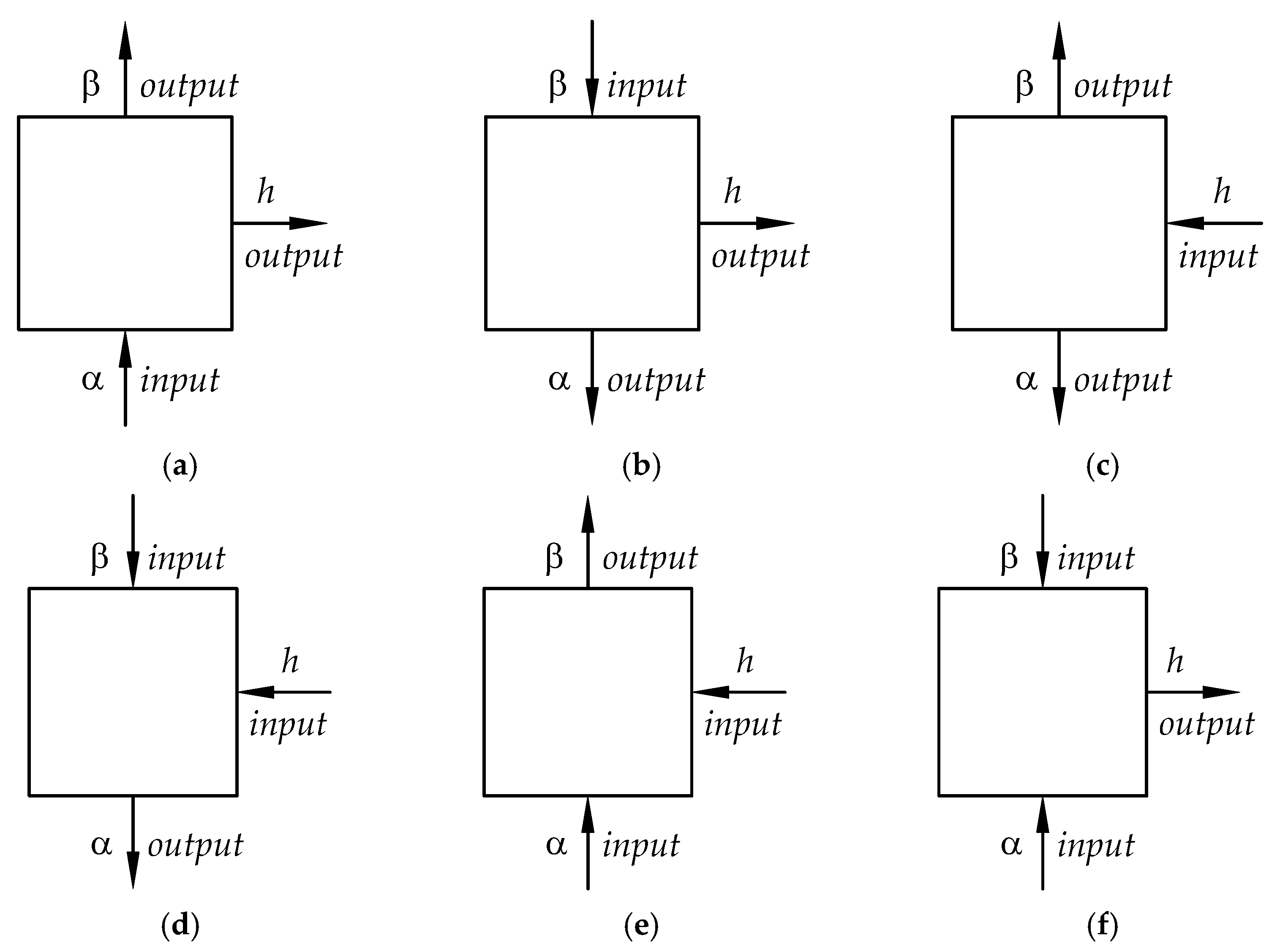
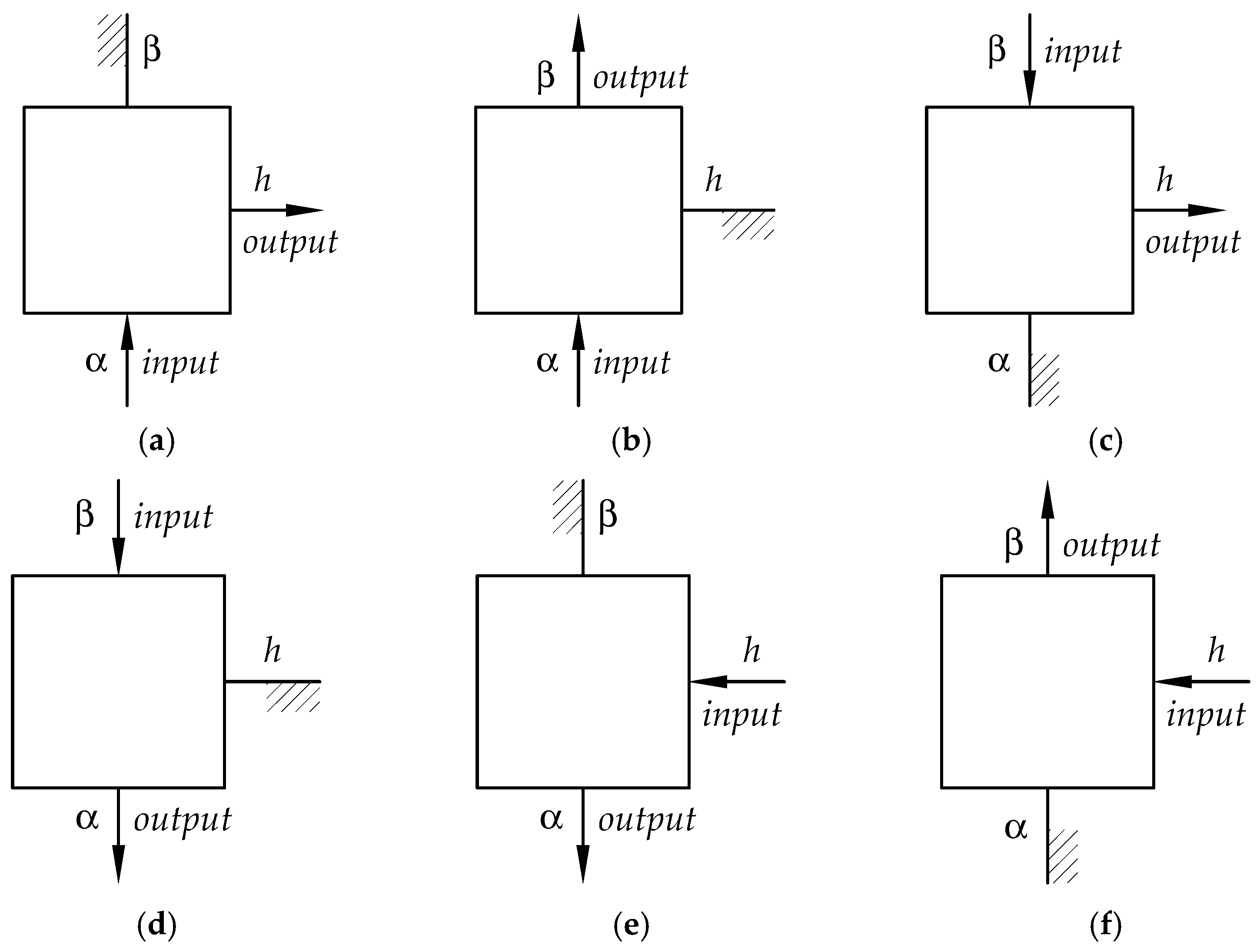
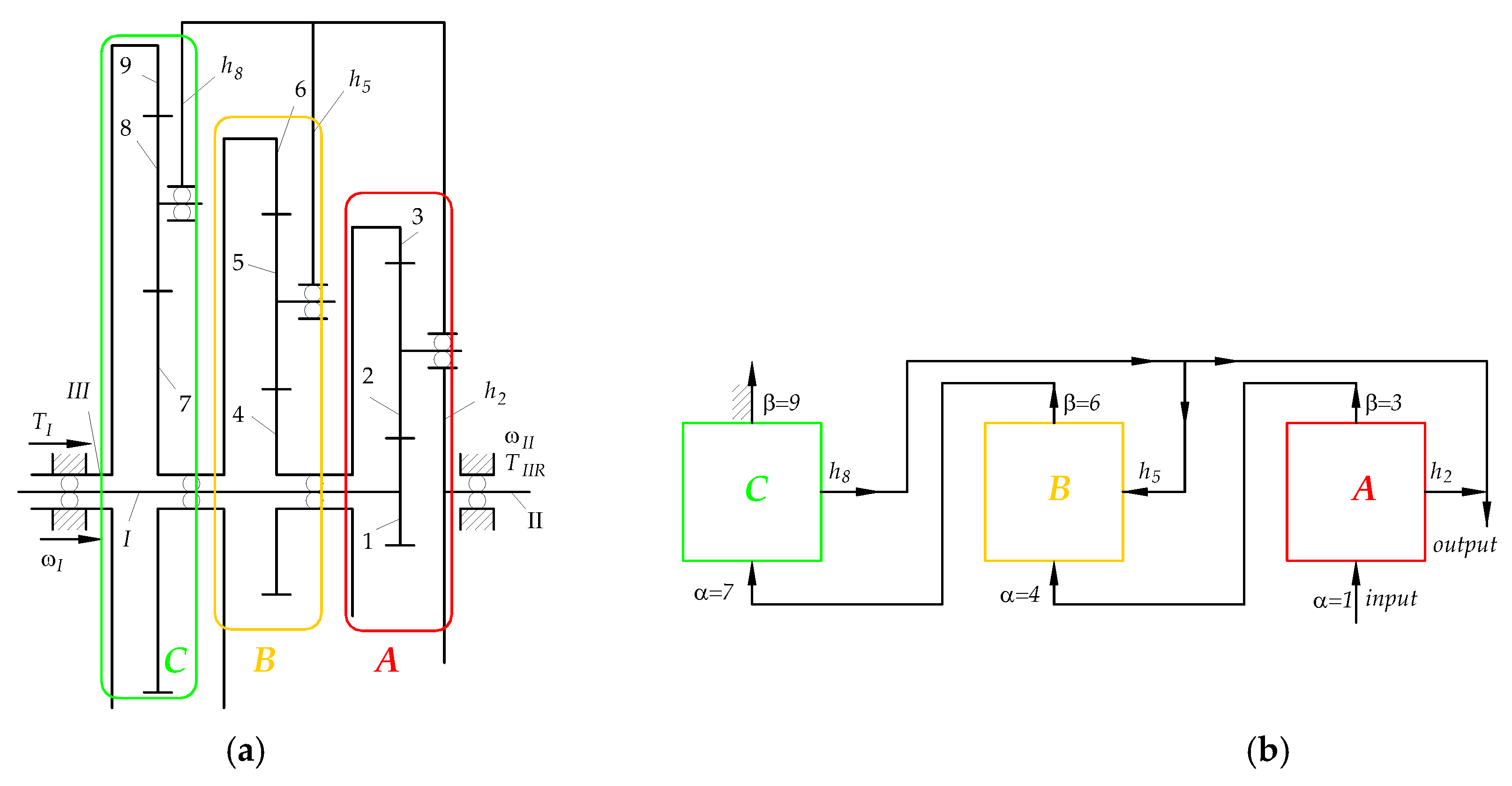
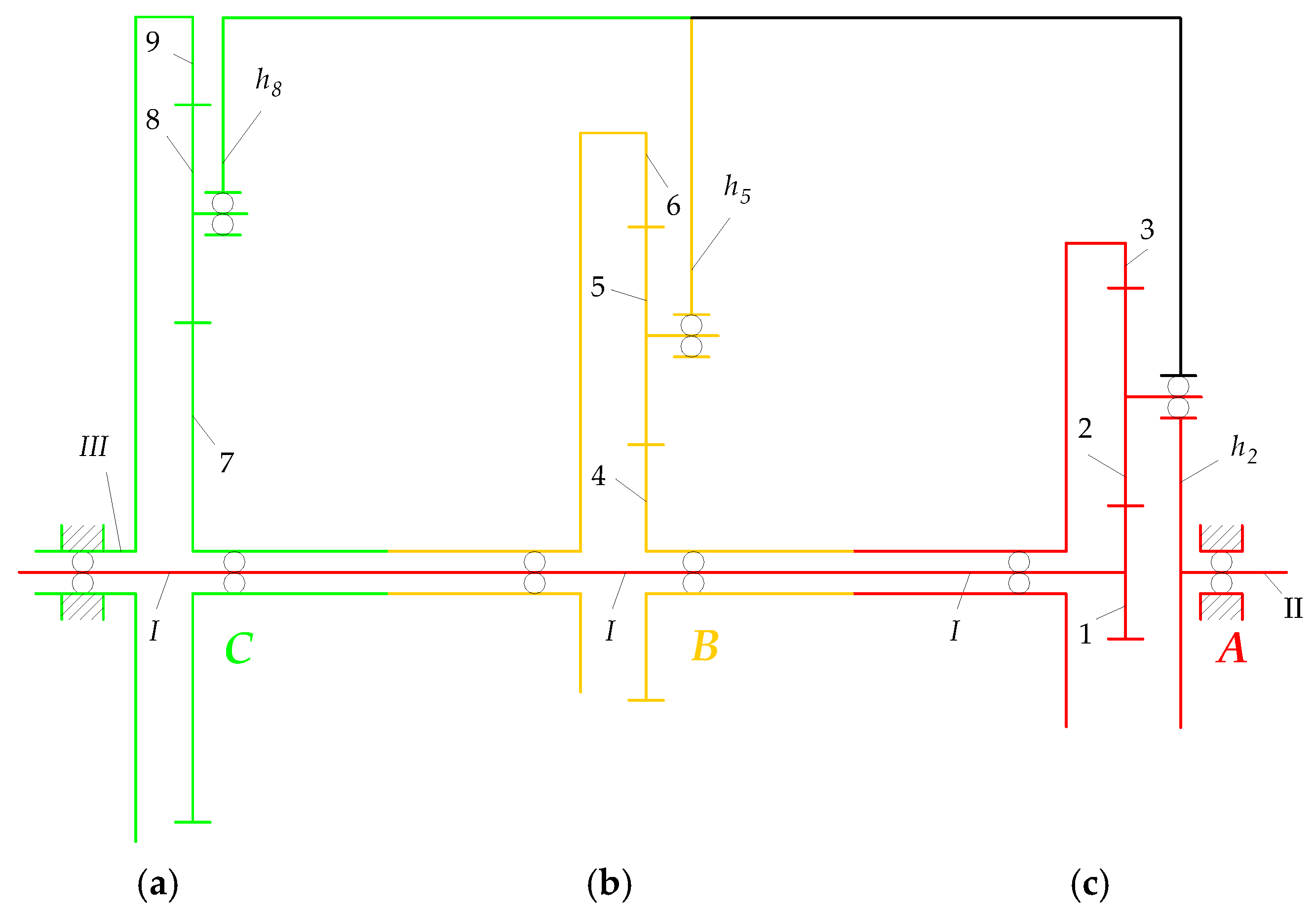

| Subsystem | |||
|---|---|---|---|
| DoF | |||
| Subsystem type |
| Subsystem A | Subsystem B | Subsystem C | ||||||
| ) | ||||||||
| Parameter | Shafts of gear or carrier No. | |||||||
| Charakter | Active | Reactive | Reactive | Active | Reactive | Active | Active | Reactive |
| Type | 2(a) | 2(a) | 2(a) | 2(e) | 2(e) | 2(e) | 1(a) | 1(a) |
Disclaimer/Publisher’s Note: The statements, opinions and data contained in all publications are solely those of the individual author(s) and contributor(s) and not of MDPI and/or the editor(s). MDPI and/or the editor(s) disclaim responsibility for any injury to people or property resulting from any ideas, methods, instructions or products referred to in the content. |
© 2023 by the authors. Licensee MDPI, Basel, Switzerland. This article is an open access article distributed under the terms and conditions of the Creative Commons Attribution (CC BY) license (https://creativecommons.org/licenses/by/4.0/).


