1. Introduction
The internal erosion of soil under the seepage flow causes the transport and loss of fine particles, which can result in significant changes in the soil structure and its mechanical properties. It is often categorized into four types in engineering: concentrated leak erosion, backward erosion, contact erosion, and suffusion [
1]. Internal erosion is one of the most common reasons for the instability or failure of water retaining structures, i.e., the earth dam and embankment. Therefore, it is of great practical significance to investigate the characteristics and mechanism of seepage erosion for cohesionless soil, which can provide references and bases for the design, construction, and long-term service of embankments or earth dams under the complex seepage condition, reducing the risk of seepage erosion.
The occurrence and development of seepage erosion is a complex dynamic process between water and soil mixture. Its occurrence is closely related to particle gradation, fines content, hydraulic conditions, etc. To study the law of seepage erosion, many scholars have carried out a lot of research and achieved many profitable results. These studies can be mainly divided into two categories: experimental tests and numerical simulations. Guidoux et al. [
2] studied the contact erosion between coarse soil and base soil, especially the cohesive base soil. They proposed an empirical expression for the critical velocity of silt/clay (or sand/clay) mixture and sand by using the effective particle diameter of base soil to calculate the critical velocity. According to laboratory tests, Liang et al. [
3] evaluated the effects of different Particle Size Distributions (PSD) and dry density of soils on the critical hydraulic gradient of seepage erosion and pointed out that the PSD has a significant effect on the internal erosion behavior of soils. Pan et al. [
4] investigated the effect of head rise rates on erosion using an indoor device and found that different head rise rates lead to different internal erosion damage patterns. The behaviors of soils are highly stochastic under seepage. Limited by the experimental methods, it is difficult to capture the process of erosion development and the change of internal contacts between particles when erosion occurs.
With the development of computer and numerical methods, numerical simulation can be a powerful supplement to experimental tests. Hu et al. [
5] used coupled Discrete Element Method and Computational Fluid Dynamics (DEM-CFD) to simulate the seepage of intermittently graded and well-graded soils. They found that the fine particle content and hydraulic gradient had significant effects on the seepage dynamics and the reduction of fine particles was accompanied by the reduction of contact with weaker force and particles with lower contact numbers. Wang et al. [
6] used a coupled DEM-CFD method to simulate the seepage of multilayered soils with different fine particle contents. They obtained that the quality of eroded soil is mainly determined by the fine particle content of underlayer soil. The higher the fine particle content of the underlayer soil, the higher the cumulative quality of eroded soil. Compared with laboratory tests, numerical simulation is more convenient and can better reveal the evolution of the seepage erosion process of soil in mesoscale. However, most previous studies have not considered the complex boundary conditions and the change of contact forces inside the soil during the seepage process. In actual engineering, the slight alteration of underlying soils below the embankment may lead to significant changes in its work performances, such as a higher flow velocity in the local area, a greater erosion extent, and a deeper damage depth. E.g., Scholtes et al. [
7] pointed out that under constant confining pressure, the dilatancy and peak stress of the soil decrease after the seepage failure. In summary, it is necessary to combine experimental methods and numerical simulations to further study the characteristics and mechanism of seepage erosion for cohesionless soil. which can provide a theoretical foundation and basis for the prevention and control of seepage erosion of embankments or earth dams.
Accordingly, this study firstly developed a self-made seepage erosion device. Based on this device, the seepage erosion process and critical hydraulic gradient of two graded soils are investigated by applying water head on samples step by step. Meanwhile, the PSD and mechanical properties of soil samples before and after the test were measured. Furthermore, the seepage erosion model for cohesionless soil was established by using the DEM-CFD coupling method. Based on this model, the migration law of fine-grain particles of soil during the seepage erosion process and the contact force chain of particle assembly were further analyzed from macroscopic and mesoscopic view.
2. Model test on seepage erosion of cohesionless soils
2.1. Material
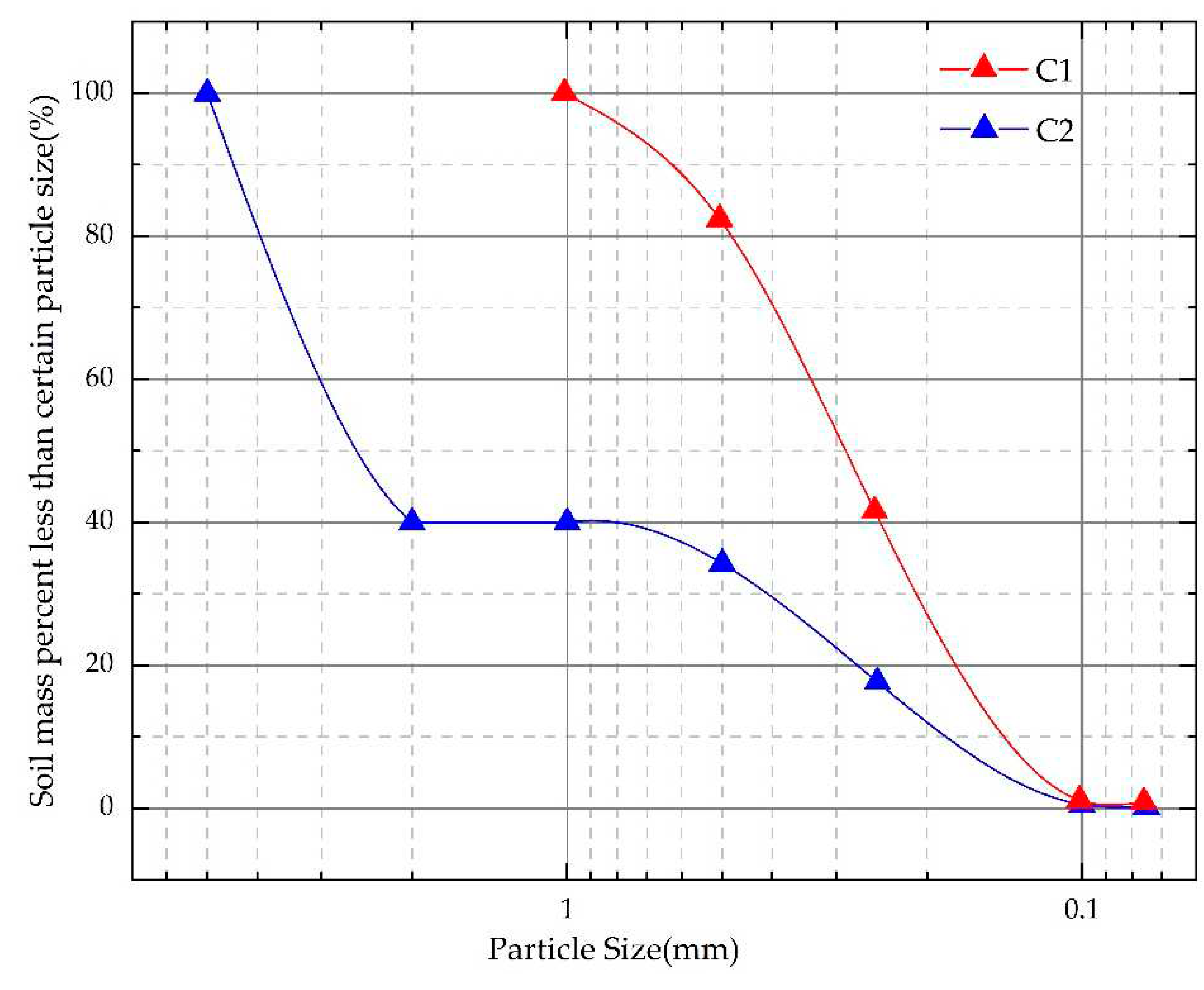
The material used in the test is quartz sand, which is rinsed, dried, and prepared for use. The sand with particle size between 0.075-0.5 mm is named the particle group C1. The particle group C2 is obtained by mixing the coarse sand (particle size between 2-4mm) with C1 at a ratio of 6:4. C1 is continuous-graded soil, and C2 is gap-graded soil, as shown in
Figure 1. The gradation curves of C1 and C2 are shown in
Figure 2. The grain composition ratio and particle size parameters of C1 and C2 are shown in
Table 1.
2.2. The seepage erosion device
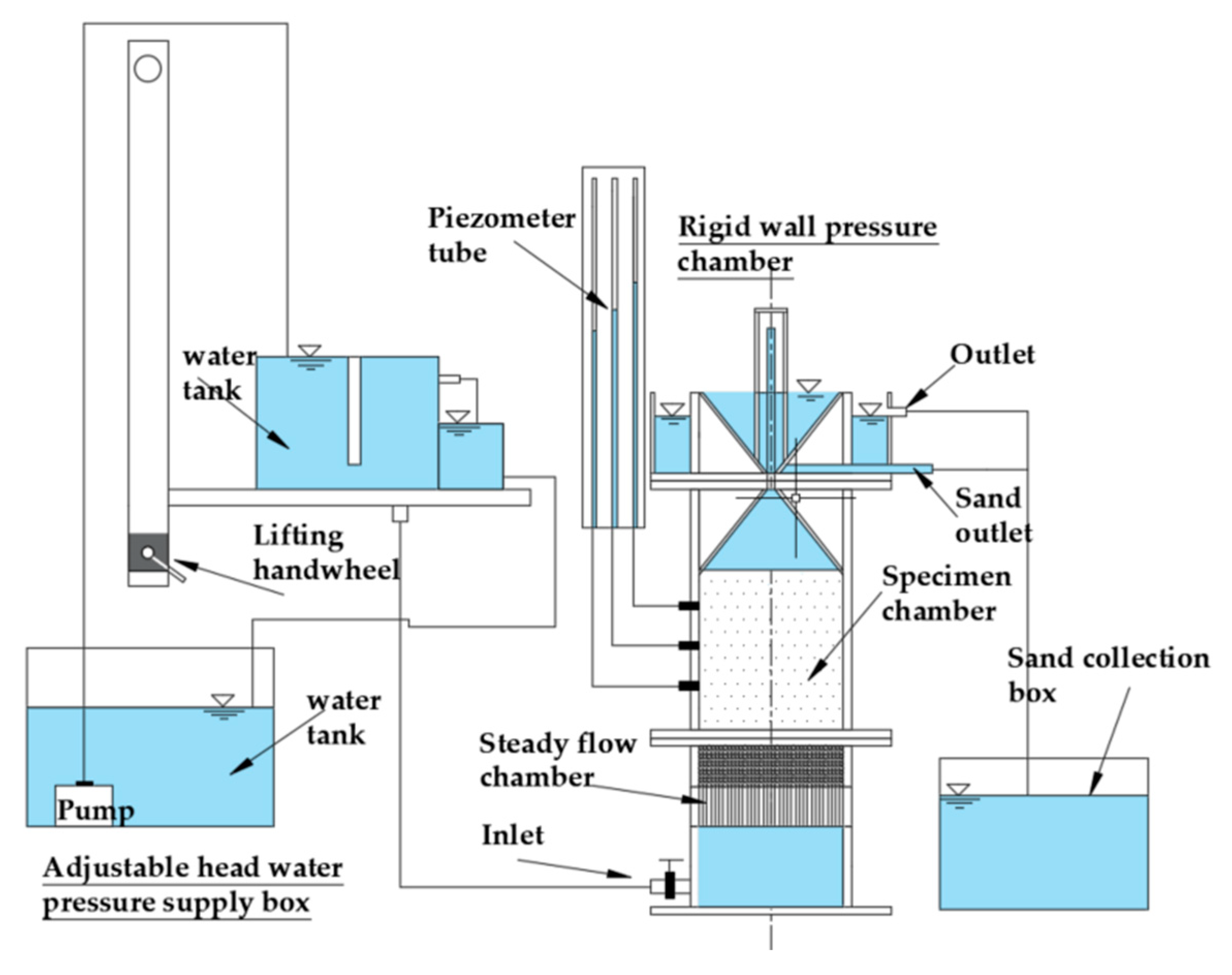
The self-made seepage erosion device and the experimental scheme are described in this section.
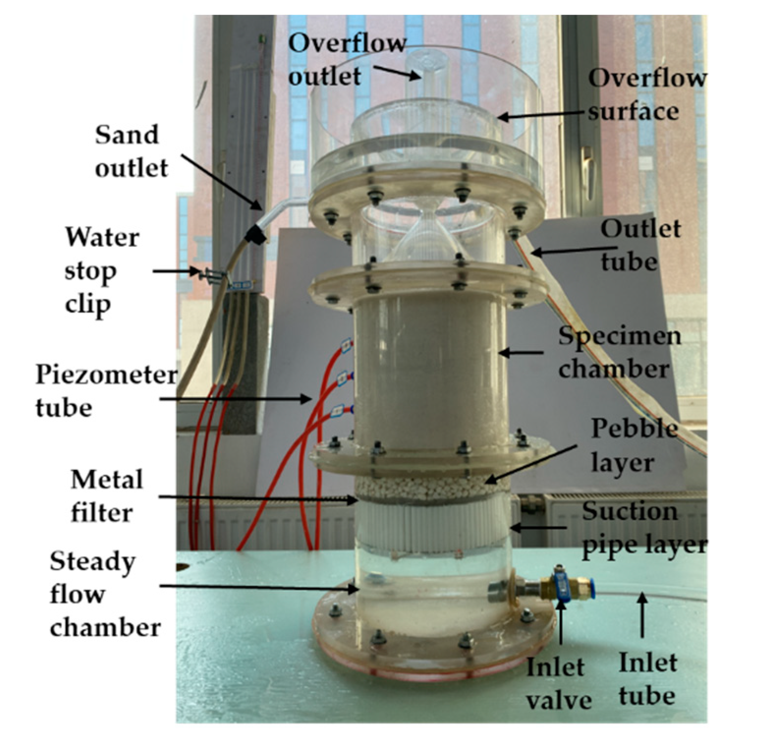
Figure 3 is a schematic diagram of the self-made seepage device. The whole device is mainly composed of 4 parts: a rigid wall pressure chamber, an adjustable head water pressure supply box, a pressure measuring tube, and a sand collection box. The rigid wall pressure chamber (Φ20 cm×60 cm) is made of transparent Plexiglas and consists of 3 parts: the steady flow chamber, the sample chamber, and the inverted siphon overflow outlet, as shown in
Figure 4. The steady flow chamber is used to smooth the water flow and avoid the water impacts, which is composed of an inlet, a 5cm high suction pipe layer, and a 5 cm high pebble layer. The sample chamber is 20 cm in diameter and 20 cm in height. Three pressure measuring heads are installed with 5 cm intervals on the side of the cylinder to measure the head, and a geotextile is laid between the steady flow chamber as a filter layer to prevent soil loss. The inverted siphon overflow outlet is made of two cones connected by a thin tube to prevent the precipitated particles from falling back into the sample chamber. This device can be used to study the seepage erosion process of cohesionless soil under increasing water head, monitor the water head change, escaping particles and water flow rate, etc.
To improve experimental accuracy, the replicate tests of seepage erosion tests were carried out. The water head was applied step by step, with each step increasing by 5cm in height and maintaining for 20 min. After each step, the water head of the pressure tube was recorded every 5min. When the difference of water head approached equality, the next level of water head would be applied. The seepage erosion process of the sample was observed and recorded by taking photos at each step during the test. When the sand overflowed into the inverted cone in a large amount, the test would be ended. Both C1 and C2 samples, which represent the continuous graded soil and gap-graded soil respectively, were applied water pressure in the bottom step by step to find the critical hydraulic gradient corresponding to the occurrence of seepage erosion.
3. DEM-CFD coupling analysis on seepage erosion of cohesionless soils
Due to the limitation of the experimental device, it is difficult to capture the migration of soil particles and the evolution of soil structure during the seepage erosion process. The DEM-CFD coupling simulations can be a powerful supplement to experimental tests to further explore the mesoscopic process of cohesionless soil under seepage erosion.
3.1. DEM-CFD coupling Method
The DEM-CFD coupling method is based on the Euler-Lagrange model [
8]. In this study, the coarse grid method proposed by Tsuji et al. [
9,
10] is used to solve the fluid phase. The fluid field is divided into a coarse grid first, and then the fluid phase is solved according to the continuity equation and Navier-Stokes equation (N-S equation) of the local average theory proposed by Anderson et al. [
11] The DEM is used to solve the solid particle system, and the drag force model is used to solve the interaction force between particles and fluid [
12]. At present, the solution of particle-fluid interaction mainly includes particle-particle interaction, fluid interaction, and particle-fluid interaction.
The particle motion in the DEM calculation is controlled by Newton's second law, and the moving process mainly includes translation and rotation, and its control equation is as follows:
where:
is the translational linear velocity of the particle
;
is the contact force acting on the particle
;
is the fluid-particle interaction force acting on the particle
;
is the gravitational force on the particle
;
is the rotational inertia of the particle;
is the rotational angular velocity of the particle
;
is the rotational moment of particle
by particle
.
For fluid motion, it is derived by local averaging of the incompressible Navier-Stokes (N-S) equation, which in turn leads to:
where:
is the divergence operator;
is the fluid unit porosity;
is the fluid density;
is the numerical calculation time;
is the velocity vector of fluid motion;
represents the fluid pressure in the fluid unit,
represents the fluid dynamic viscosity,
is the total volume force per unit volume applied to the fluid unit by the particles in the fluid unit, and
represents the gravitational acceleration.
In this study, the effects of drag force
and buoyancy
are considered. Drag force is the main force affecting the interaction between particles and fluids. At present, many researchers [
13,
14,
15] have studied and given expressions for fitting the drag force model of porous media. In this paper, we use Di Felice [
13] obtained from the drag force
on a single particle during smooth settling within a fluid multiplied by a function related to the porosity
of the stacked body, expressed in the following form:
where:
denotes the empirical correction term considering local porosity, which makes the force applied to both high-porosity and low-porosity systems, and applies to the large Reynolds number range [
16];
is the empirical coefficient related to local porosity, see Equation (5);
denotes the fluid drag force applied to a single particle. The fluid drag force on a single particle can be calculated using Equation (6):
where:
is Reynolds number;
denotes the drag coefficient, formula reference;
represents the particle diameter;
is the particle velocity vector.
The second part of the force is the buoyancy force caused by the fluid pressure, which is calculated by the formula:
where:
represents the particle volume.
In summary, the fluid-particle interaction force can be expressed by the following equation:
3.2. DEM-CFD Model of seepage erosion for cohesionless soils
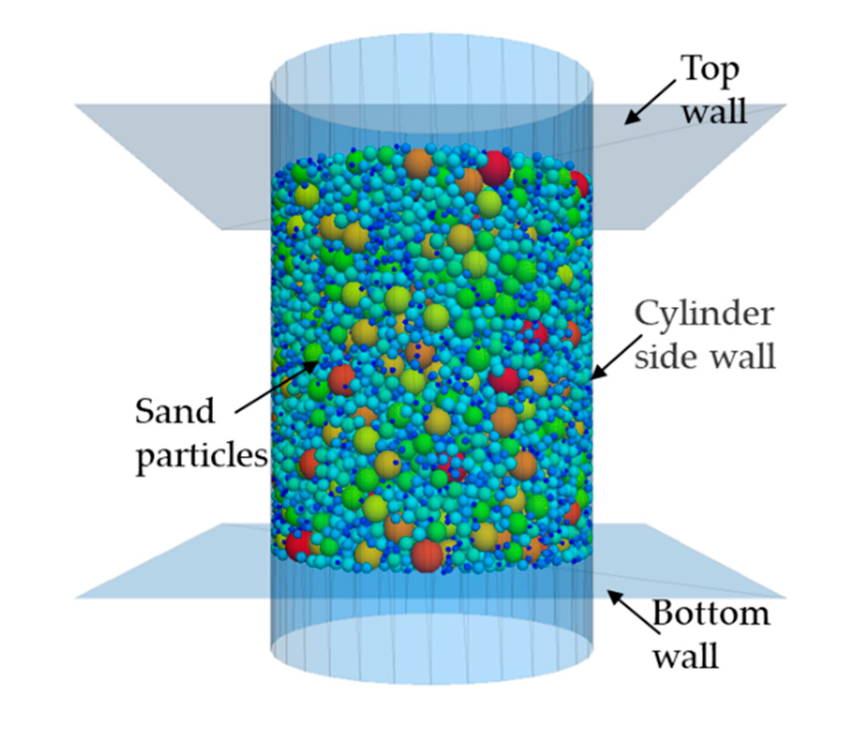
Based on the laboratory test, a numerical model is established as shown in
Figure 5. To improve the computational efficiency of the model, a scaling model is established, i.e., the sizes of numerical samples were reduced by 10 times compared to the real samples. The numerical model is a cylinder with a diameter of 1.8 cm and a height of 2.0 cm. First, we built an impermeable cylinder as a sample container and generated two square walls at the top and bottom. The cohesionless soil particles are represented by spheres of different sizes. The linear contact model is used to describe the behaviors between particles and particles, and between particles and walls. The influence of sand particle shape is reflected by the higher friction coefficient. The soil particles are generated in the cylinder with specified initial porosity and PSD. The soil particle size in the model was scaled up to three times compared with the actual soil to further reduce the computational load.
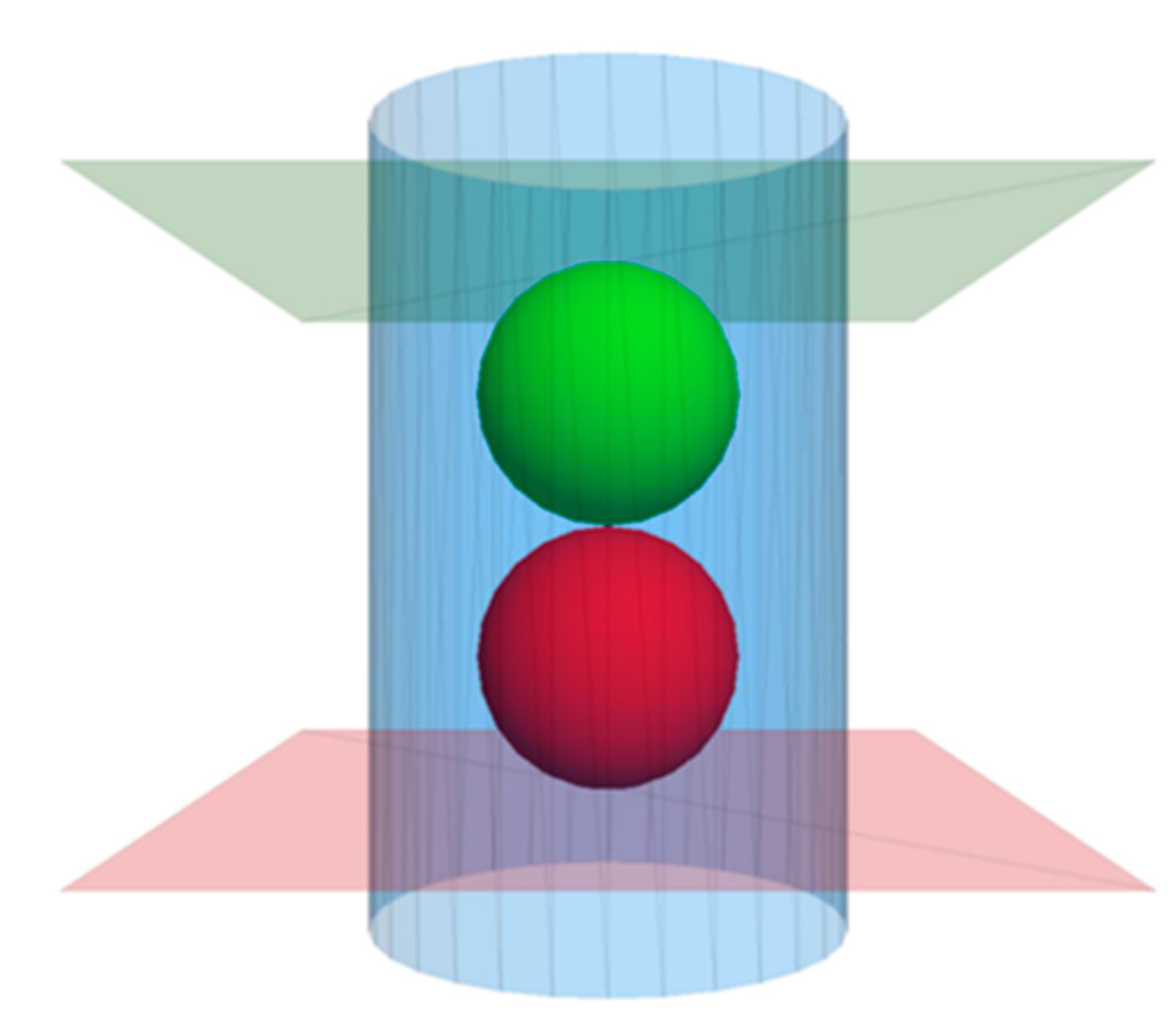
To monitor the state change and structure evolution of the particle assembly during the seepage process, two measuring balls with a 5mm radius are created in the middle of the sample. The positions of the measuring balls are on the central axis of the cylindrical model. As shown in
Figure 6, the red ball is the No.1 measuring ball, and the green is the No.2 measuring ball.
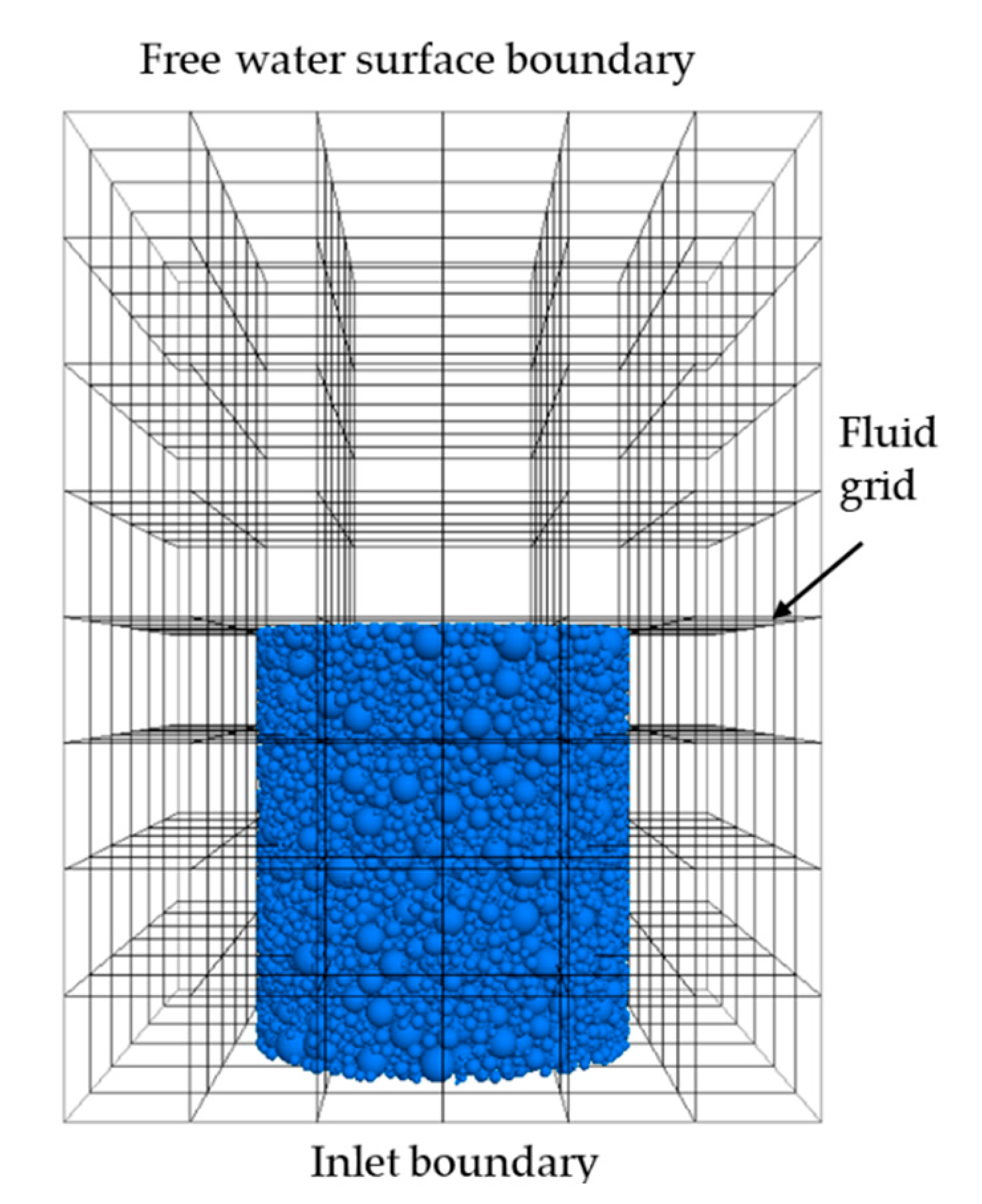
Finally, the fluid field is meshed and the fluid boundaries are determined. The fluid domain includes the whole DEM model. According to the laboratory tests, the seepage direction is upward and the gravity direction is downward. The lower boundary of the fluid mesh is set as the inlet with specific pressure, and the upper boundary is set as the outlet with zero pressure. The surrounding boundary conditions are set to impervious wall boundary, as shown in
Figure 7. The model parameters are shown in
Table 2.
4. Results and discussion
4.1. Experimental phenomenon and critical hydraulic gradient analysis
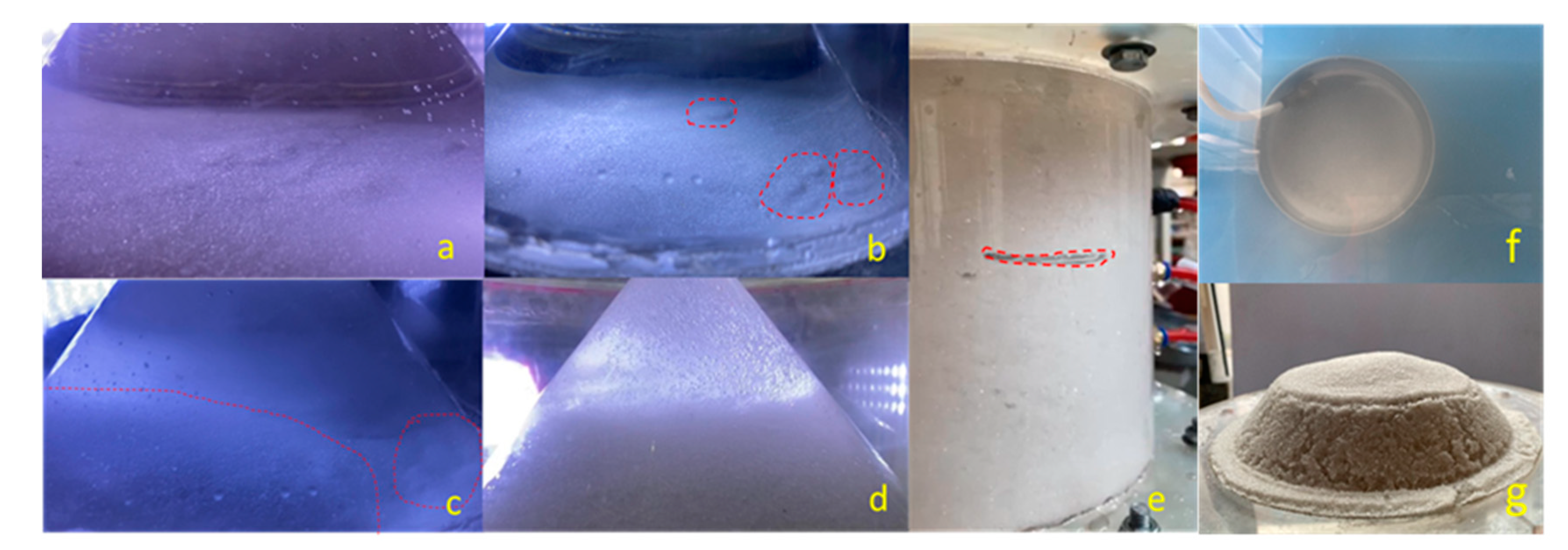
Figure 8 shows the development of seepage occurring in sample C1. At the beginning of the experiment, the sample was stable and no significant movement of sand was observed, as shown in
Figure 8a. As the water head increases, the sand sample gradually became fluffy, accompanied by tiny bubbles emerging. The water head continues to increase, some small bulges appeared at the top of the sample and increasing fine particles begin to jump, as shown in
Figure 8b. Continuing to increase the water pressure, the sand particles at the bulge continued to gush out, forming circles on the sample surface and expanding. The sand expanded and accumulated on the surface, and the water flow became turbid, as shown in
Figure 8c. Further increasing the water pressure, the sand sample was pulled apart between the horizontal cracks (
Figure 8e). The water flowed along the side walls in a circular expansion and rose, the sample was destroyed. The top sand sample overturned obviously, and a large amount of sand gushed into the cone (
Figure 8d). Due to the continuous seepage, the finer particles would be brought to the upper cone sand flushing port. Then the finer particles flow into the sand collection box with the water flow (
Figure 8f). When the sample is eroded by seepage, the whole sand sample expands and lots of pores appear on the surface of the sand sample after erosion (
Figure 8g). It can be observed that a small number of fine particles remain on the surface of the cone. This indicates that the actual mass of eroded fine particles of the sample under the action of seepage is larger than the collected mass.
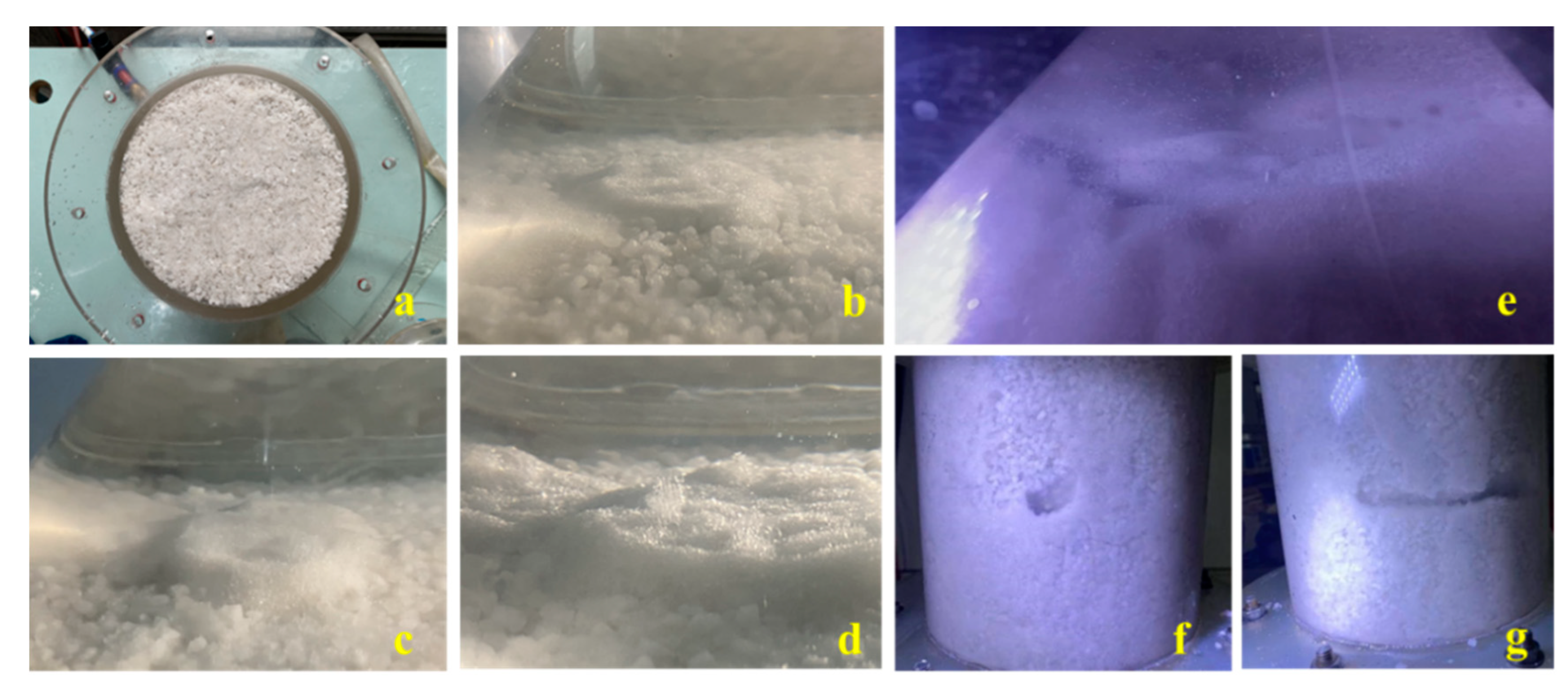
The C2 sample experimental phenomenon is consistent with the C1 sample process. However, the water head required for the sand gushing of C2 sample is higher. Under the action of seepage flow, the C2 sample would produce tiny bubbles and gradually form the seepage channels in early stage. Subsequently, the phenomenon of gravel boiling appeared at the top surface. With the water head increasing, sand boiling intensified and occurred in multiple areas, causing lots of bulges on the surface of the sample, as shown in
Figure 9 (b) ~ (d). As the water head continues to increase, the entire sample undergoes expansion. Many sands at the top of the sample were gushed out along the cone, and the water flow became turbid, as shown in
Figure 9 (e). Further increasing the water head, the fine sand at the side wall of the sample was brought out in large quantities under the seepage flow, and the pores between the coarse particles increased to form an obvious depression, as shown in
Figure 9(f). Under the continuous action of the water head, a clear seepage channel appeared in the middle of the sample, and the fine particles begin to scour along the sidewall, as shown in
Figure 9(g).
The development process of seepage erosion of C1 and C2 graded samples are approximately the same, which is consistent with the study of Fleshman and Rice [
17]. The seepage erosion of the sandy soil can be divided into four stages: stable seepage stage, fine particles upward migration stage, sand samples boiling stage, and erosion damage stage.
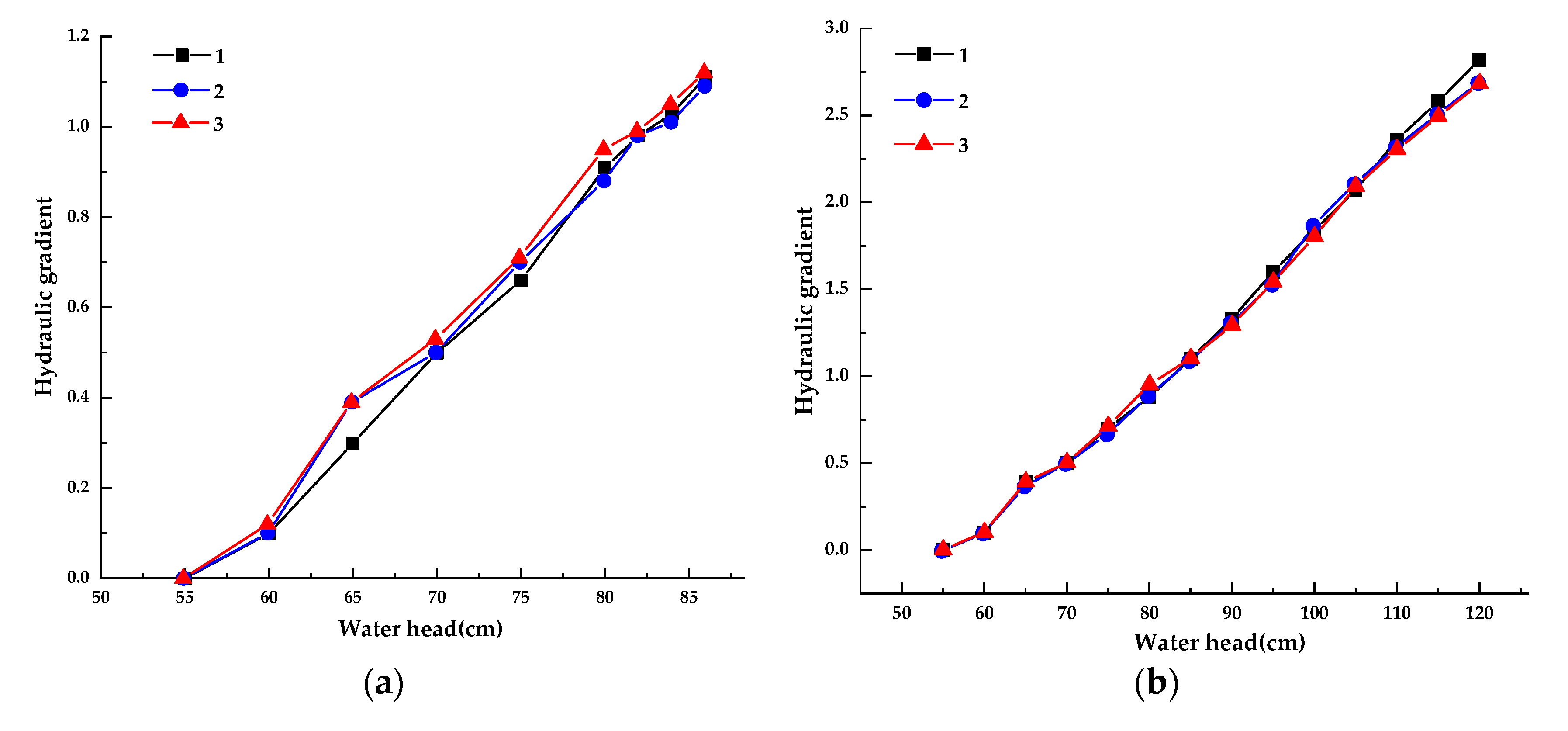
Figure 10 shows the change in the water head-hydraulic gradient of the C1 and C2 samples. The first test sand of the C1 sample started to bulge when the water head was 80 cm. After the fine particles moved upward, the water head was gradually increased with a head difference of 2 cm at a time. In both the second ad the third experiments, the water head was 82 cm when the fine particles began to move upward. The critical hydraulic gradient can be calculated by the pressure tube data. The critical hydraulic gradient for the three experiments is 0.91, 0.98, and 0.99. By averaging the three experiments, the critical hydraulic gradient for seepage erosion in the C1 sample is 0.96. As the water head rises, the sand is violently overturned and finally destroyed.
The critical water head of the C2 sample for three tests is 110cm, 105cm, and 105cm. According to the pressure tube data, the critical hydraulic gradient can be calculated as 2.36, 2.11, and 2.09, respectively. The first test data may be large due to the operation problem during the test. So we averaged the data of the remaining two sets of tests, and obtain the critical hydraulic gradient of C2 test soil as 2.1. It can be seen that the required hydraulic gradient is elevated by using a mixture of coarse-grained quartz sand and fine-grained quartz sand. This is because the fine sand is better bonded to the coarse sand and the soil becomes more capable of withstanding seepage.
4.2. Mesoscopic analysis of seepage erosion process and particle migration law
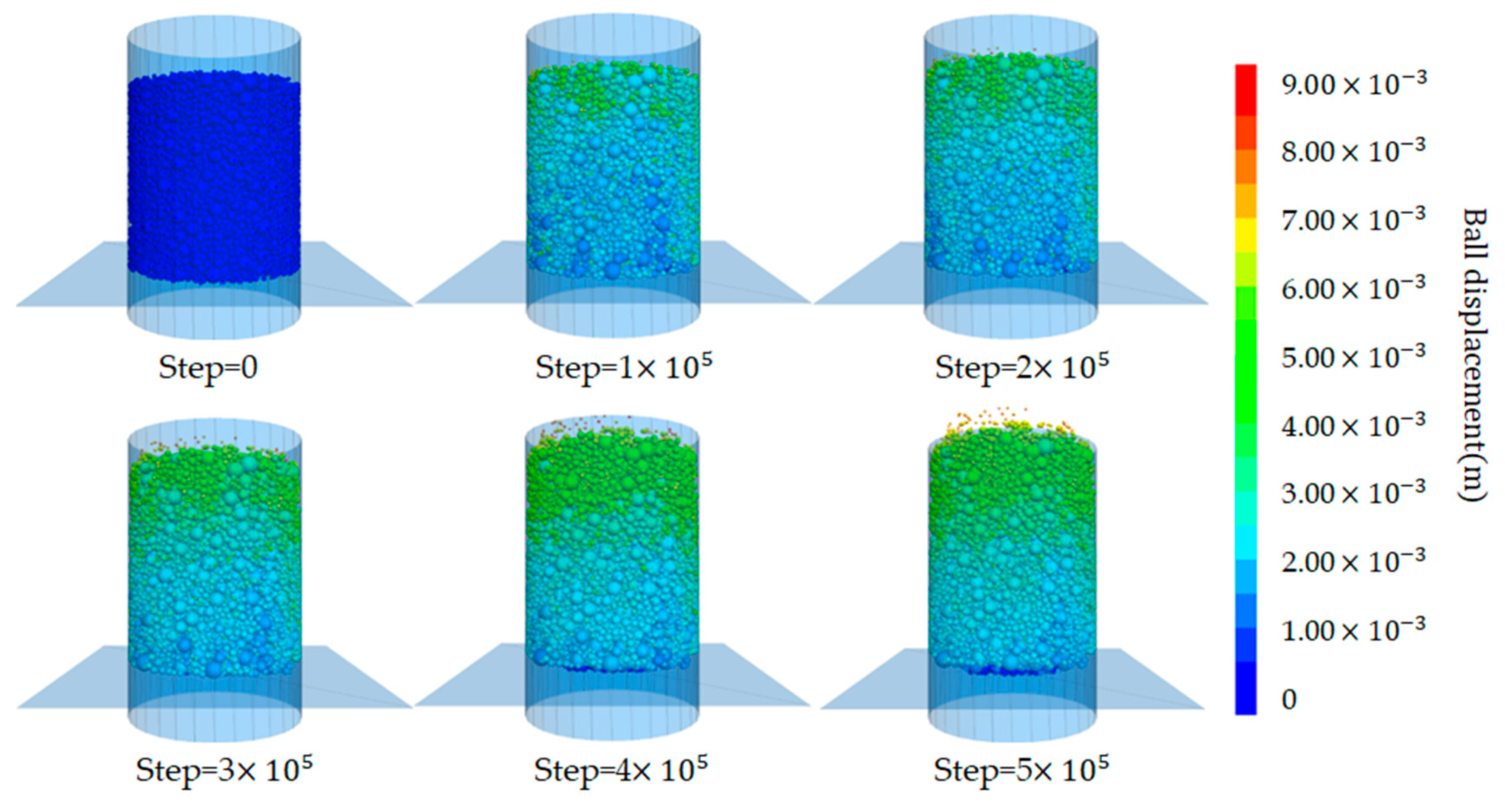
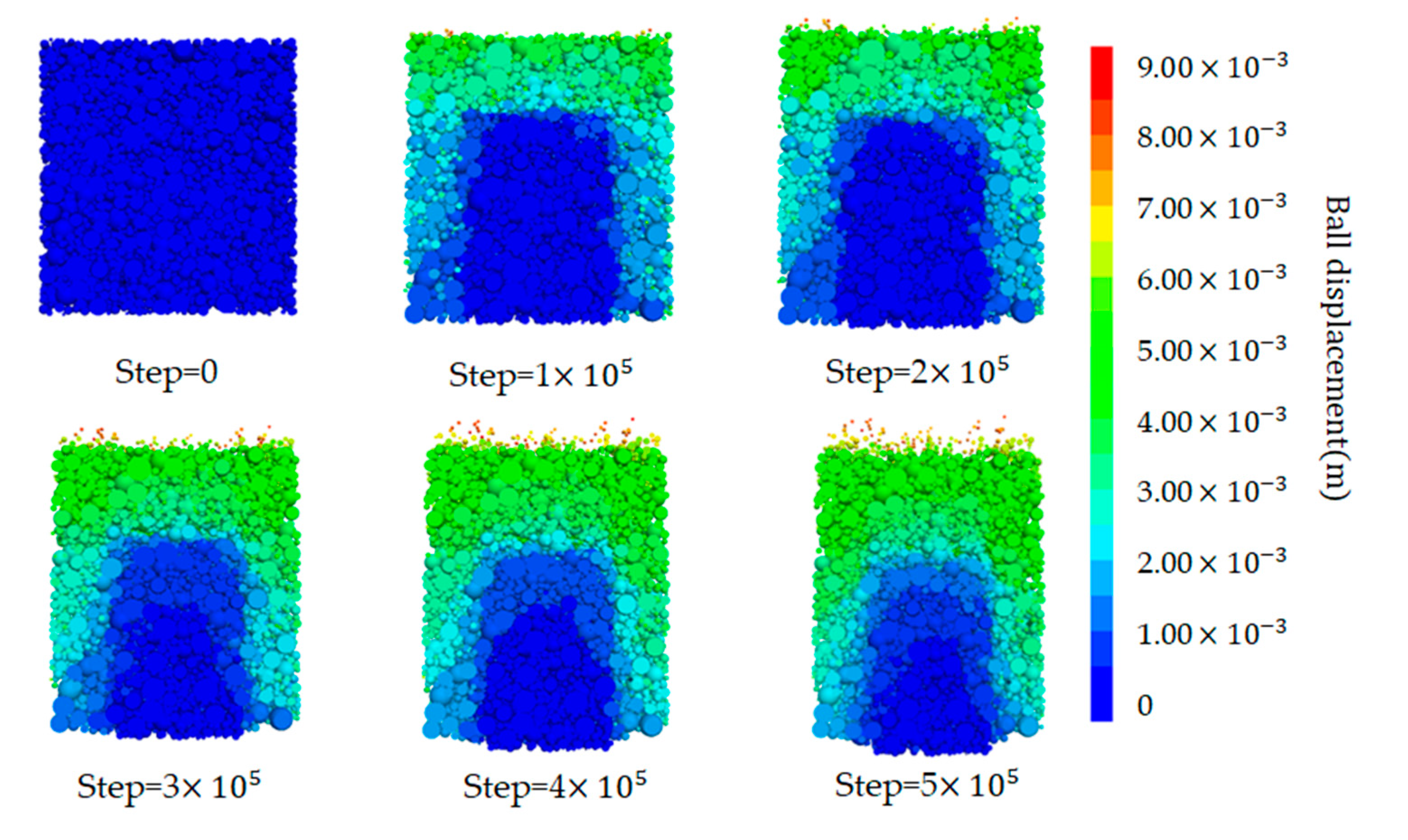
Figure 11 and
Figure 12 respectively show the model particle displacement scalar diagram and the model particle displacement section diagram in different periods. When the model runs for 100,000 steps in
Figure 11, the particles in the surface layer under the action of the water flow first initiate a large displacement, and mainly fine particles are washed out. According to
Figure 12, it can be seen that the central particles are denser, and the migration distance that occurred is not long. Due to the small friction coefficient between the rigid wall and the particles, the particles in contact with the wall surface also occurred in different degrees of displacement. The loss of fine particles shows the overall instability failure. Due to the loss of fine particles, the gap in the middle of the soil becomes larger. Finally, the whole soil particles appear to move upward.
According to the numerical results, the seepage erosion of cohesionless soil is divided into four stages in this study:
(1) Stable seepage stage
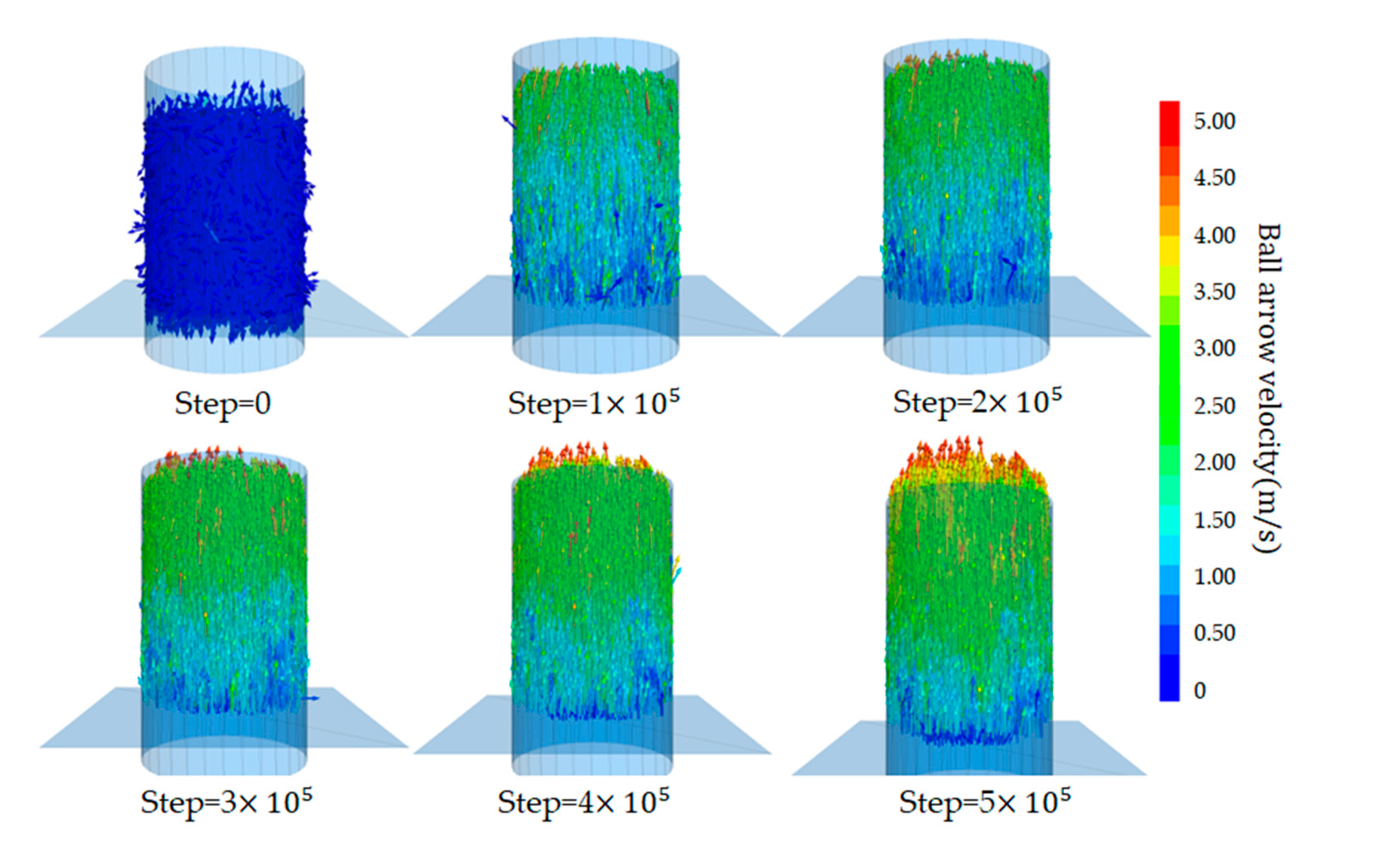
In the initial stage of seepage, gravity, and fluid force are applied to the particles. The particles are subjected to upward water pressure and buoyancy, and downward gravity and drag force. From
Figure 13, it can be seen that the overall velocity of the particles in the initial situation is downward, and the velocity of a small number of particles on the surface is upward. This is because the water pressure is low, and the particles settle downward under gravity. This process lasts a short time. Due to the increased water pressure, the force on the particles is in balance with the seepage force, and the particles are stable under the action of water pressure.
(2) Fine particle upward migration stage
As the water pressure continues to increase and reaches a certain critical value, the fine particles inside the sample are clearly displaced. It can be seen from
Figure 11 that the fine particles on the surface of the sample first generate displacement at 100 thousand steps. The upper particles of the sample flow upward under the action of seepage, and the sample began to become fluffy. As can be seen from
Figure 12, the displacement of particles in the bottom area of the sample is less. As the water pressure increases, the particles begin to show varying degrees of displacement and some loss of fine particles has occurred. The loss of fine particles at this stage can be taken as an important sign that seepage damage begins to occur in the sample. The seepage channel begins to form inside the sample, with a hydraulic gradient of about 2.0 at this stage.
(3) Skeleton particle loosening stage
Increasing the water pressure, the fine particles inside the sample are taken out in large quantities. The porosity inside the soil increases and the permeability coefficient of the upper part of the sample increases accordingly. Therefore, the ability of the upper unit to bear the water head also decreases, and the particle velocity increases sharply, as shown in the 300-thousand-step diagram in
Figure 13. With the loss of fine particles, some weak areas and voids appear in the upper region of the sample, and the skeleton particles inside the soil move upward, and this stage occurs at a hydraulic gradient of about 6.0.
(4) Complete failure stage
With the initiation of the skeleton particles, the overall stability of the soil decreases and the internal erosion becomes severe. Continuing to increase the water pressure, The soil inside the sample began to destabilize, resulting in infiltration erosion damage. A large number of particles move towards the outlet, as shown in
Figure 11 in the 400-thousand-step and 500-thousand-step. At this time, the overall porosity of the model also increases, the model volume expands, and the inter-particle contact numbers continue to decrease. With the massive loss of particles in the upper region, the pressure on the particles in the lower area decreases, and the lower area begins to move upward. The contact inside the model becomes sparse, and at this point, the model is destroyed. This is consistent with the laboratory experiment results, the water head rises to a certain extent, and the sample is destroyed. This stage occurs at a hydraulic gradient of about 9.0.
4.3. Mesostructural characteristics of soil particles during the seepage erosion process
In order to quantitatively describe the damage degree of seepage erosion, the erosion rate parameter is introduced to represent the amount of particle loss inside the soil. According to the model of this paper, the erosion rate is defined as the ratio of the mass of sand particles washed out of the model device (i.e., the mass of eroded particles) to the mass of all sand particles in the barrel before the start of seepage, which is calculated as follows.
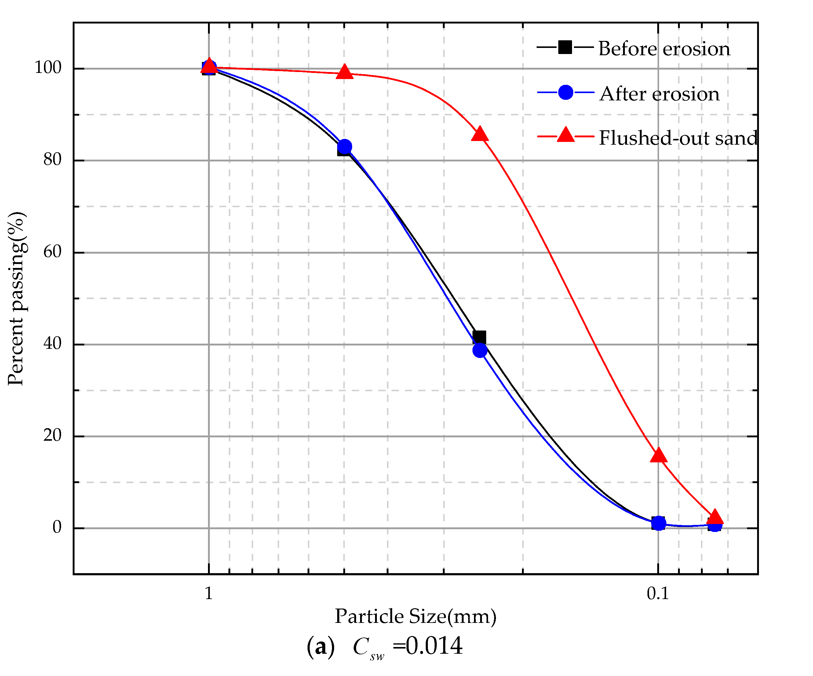
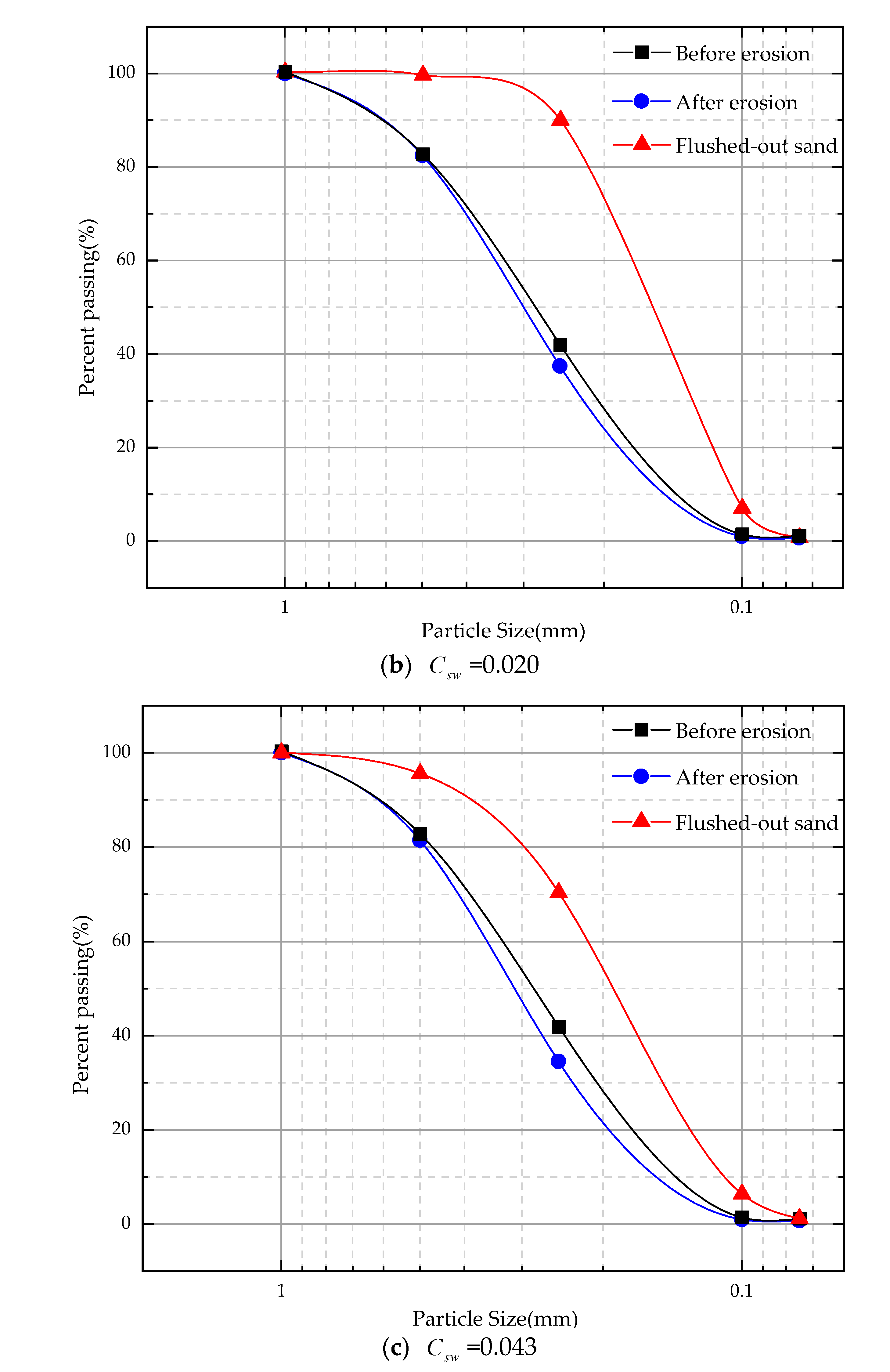
After the laboratory test, the residual samples in the container and the precipitated sand particles in the sand collection box are recovered, dried, sieved, and weighed. Then we compare it with the PSD before the test to analyze the change of particle gradation under different erosion rates. According to the change of distribution, the sieve analysis was carried out on the dried soil material after erosion and the gradation curve was drawn. This section mainly analyzes the gradation before and after the erosion of the C1 sample, as shown in
Figure 14.
According to the gradation curves of the samples before and after erosion at the three erosion rates shown in
Figure 14, it can be seen that after the seepage test, the particle gradation curve shifted downward compared with the initial particle gradation curve. The degree of deviation of the gradation curve after erosion is proportional to the amount of particle loss. The greater the erosion rate, the greater the deviation of the gradation curve, which indicates that more particles precipitate out, leading to a change in the internal particle composition structure of the soil. The internal structure of the soil is rearranged during the seepage process. The parameters characterizing the soil gradation at different erosion rates can be obtained by calculation, as shown in
Table 3.
As shown in
Table 3, the average particle size of the eroded particles tends to increase with the erosion rate, and the fineness modulus also tends to increase. For the same graded fine aggregate, the smaller the fineness modulus of the sand, the finer the particles. With the increase of the erosion rate, more fine particles are lost inside the sample. The fineness modulus of the precipitated particles also increases with increasing erosion rate, which indicates that the loss of coarse particles will increase with seepage development. Initially, fine particles on the surface are lost first under upward percolation conditions, and fine particles inside the sample are transported and lost through the gaps in the coarse particles. When the hydraulic gradient reaches the start-up hydraulic gradient, the fine particles begin to transport and continuously fill the formed voids, thereby forming a blockage or channel between the skeleton particles. When the hydraulic gradient increases, the soil is insufficient to resist the seepage force, and the soil skeleton starts to deform and rearrange. Soil deformation is the formation of strong chains between coarse particles, and fine particles provide lateral support for these force chains. When the fine particles continue to lose, water flow continuously weakens the lateral support forces, resulting in changes in the soil's internal structure and thus causing overall instability and deformation.
4.4. Influence and mechanism analysis of seepage erosion on the mechanical properties of soil
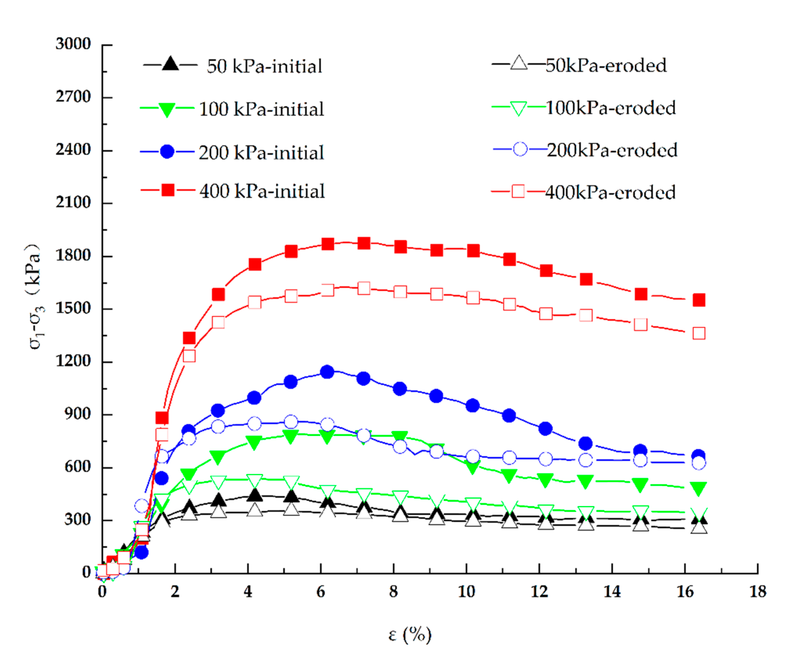
In order to explore the difference in mechanical properties before and after seepage, the C1 sample is mainly analyzed. Triaxial drainage tests were carried out on sand samples with an erosion rate of
=0.014 before and after erosion. The deviatoric stress-strain curves before and after erosion are shown in
Figure 15. The square represents the pre-erosion curve and the triangle represents the post-erosion curve. According to the diagram, with the increase of confining pressure, the deviatoric stress of soil increases, and the shear strength increases. Under different confining pressures, the deviatoric stress of the sample reaches a peak when it is close to 5 %, and then decreases slowly. When the strain is 16 %, it has not yet reached a stable critical state, showing a certain strain-softening behavior. The strength of soil after seepage erosion is lower than that before erosion, which is due to the loss of internal fine particles caused by seepage erosion, and the soil shows lower mechanical strength.
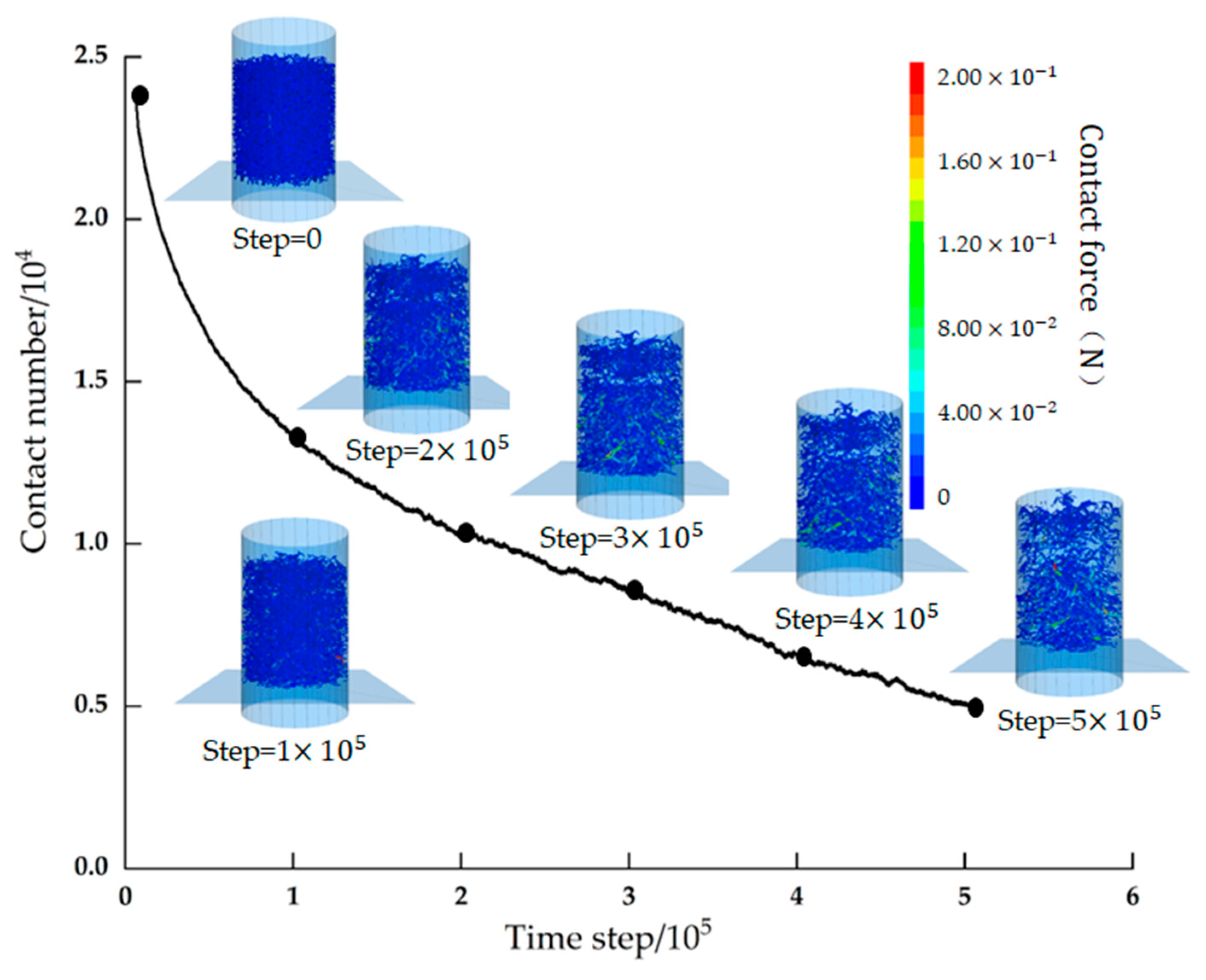
Figure 16 show the change of contact force and contact number between particles during numerical simulation. In
Figure 16, the thin cylinder represents the weak contact force between fine particles, and the thicker cylinder represents the contact between skeleton particles and between skeleton particles and the wall. As can be seen from
Figure 16, the overall number of model contacts decreases with increasing time steps. In
Figure 16, due to the large loss of fine particles in the upper area, the contact between particles is seriously reduced, which has an impact on the model structure. The contact reduction in the lower area is relatively small due to the upper pressure. The strength of the contact force of the sample shows different strengths in different periods. It can be seen from the contact bond color change, the upper part shows a weak force chain and the lower region shows a certain strong force chain due to the filling and squeezing between the particles, which increases the pressure on the skeleton particles and the transfer of stress between the skeleton. With the fine particles decrease, the strong force chain gradually decreases and the weak force chain gradually increases. This is consistent with the above physical experimental results. As the pressure gradient increases, the particle spacing increases, the number of contacts decreases, the contact force decreases, and the mechanical properties of the soil decrease, resulting in the instability of the skeleton stress transfer structure. In general, under the action of seepage, the decrease of contact between particles caused by the loss of fine particles leads to a change in soil mechanics and structure, which eventually leads to the instability and failure of the whole sample.
5. Conclusions
In this study, we studied the characteristics and mechanism of seepage erosion for cohesionless soils by model tests and DEM-CFD coupling simulations. According to the experimental and numerical results, the migration law of fine particles and the critical hydraulic gradient of seepage erosion for cohesionless soils are analyzed. Moreover, the change in framework structure and mechanical properties of cohesionless soils before and after erosion are discussed. Specifically, the following conclusions were drawn:
(1) A self-made seepage erosion device for cohesionless soil was developed, which can be used to observe the seepage erosion process, measure the critical hydraulic gradient of seepage erosion, and investigate the escaping particles during the seepage erosion process.
(2) The seepage erosion process of cohesionless soil can be divided into four stages: stable seepage stage, fine particles upward migration stage, sand samples boiling stage, and erosion damage stage.
(3) Mixing with coarse-grain sand can increase the critical hydraulic gradients of the fine-grain quartz sand sample. Because the coarse-grain sand can improve the soil structure and force chain of fine-grain sand samples.
(4) The increasing erosion ratio means more loss of fine sand particles and the increase of pore structure between soil skeleton. These changes may result in the rearrangement of soil particles, i.e., the decrease of contact number and the weakening of contact force, which will lead to the strength decrease.
References
- Xiukai, W. , et al., Review on Numerical Simulation of the Internal Soil Erosion Mechanisms Using the Discrete Element Method. Water, 2021. 13(2).
- Guidoux, C. , et al., Contact Erosion at the Interface between Granular Coarse Soil and Various Base Soils under Tangential Flow Condition. Journal of Geotechnical & Geoenvironmental Engineering, 2010. 136(5): p. 741-750.
- Liang, Y. , et al., Onset of suffusion in gap-graded soils under upward seepage. Soils and Foundations, 2017. 57(5). [CrossRef]
- Ming, P. , et al., Experimental study on internal erosion and seepage in the foundation of a dike under variable water head. European Journal of Environmental and Civil Engineering, 2021(12): p. 1-16.
- Hu, Z., Y. Zhang and Z. Yang, Suffusion-induced deformation and microstructural change of granular soils: a coupled CFD–DEM study. Acta Geotechnica, 2019. 14(3). [CrossRef]
- Pei, W. , et al., CFD-DEM modelling of suffusion in multi-layer soils with different fines contents and impermeable zones. Journal of Zhejiang University-SCIENCE A, 2022. 24(1).
- Scholtes, L., P. Y. Hicher and L. Sibille. A micromechanical approach to describe internal erosion effects in soils. International Symposium on geomechanics and geotechnics: from micro to macro. 2011. IS-Shanghai.
- Zhou, H. , et al., A Novel, Coupled CFD-DEM Model for the Flow Characteristics of Particles Inside a Pipe. Water, 2019. 11(11). [CrossRef]
- Tsuji, Y., T. Tanaka and T. Ishida, Lagrangian numerical simulation of plug flow of cohesionless particles in a horizontal pipe - ScienceDirect. Powder Technology, 1992. 71(3): p. 239-250.
- Tsuji, Y., T. Kawaguchi and T. Tanaka, Discrete particle simulation of two-dimensional fluidized bed. Powder Technology, 1993. 77(1): p. 79-87. [CrossRef]
- Anderson, T.B. and R. Jackson, Fluid Mechanical Description of Fluidized Beds. Stability of State of Uniform Fluidization. Industrial & Engineering Chemistry Fundamentals, 1968. 7(1): p. 12-21.
- Zhao, J. and T. Shan, Coupled CFD–DEM simulation of fluid–particle interaction in geomechanics. Powder Technology, 2013. 239.
- Di Felice, R. , The voidage function for fluid-particle interaction systems. International Journal of Multiphase Flow, 1994. 20(1). [CrossRef]
- Ergun, S. , Fluid Flow through Packed Columns. Engineering, 1952. 48: p. 89-94.
- J., H.R., K. J., H.R., K.D. L. and L.A.J. C., Moderate-Reynolds-number flows in ordered and random arrays of spheres. Journal of Fluid Mechanics, 2001. 448.
- Xu, B.H. and A.B. Yu, Numerical simulation of the gas-solid flow in a fluidized bed by combining discrete particle method with computational fluid dynamics. Chemical Engineering Science, 1997. 52(16). [CrossRef]
- Fleshman, M.S. and J.D. Rice, Laboratory Modeling of the Mechanisms of Piping Erosion Initiation. Journal of Geotechnical and Geoenvironmental Engineering, 2014. 140(6). [CrossRef]
|
Disclaimer/Publisher’s Note: The statements, opinions and data contained in all publications are solely those of the individual author(s) and contributor(s) and not of MDPI and/or the editor(s). MDPI and/or the editor(s) disclaim responsibility for any injury to people or property resulting from any ideas, methods, instructions or products referred to in the content. |
© 2023 by the authors. Licensee MDPI, Basel, Switzerland. This article is an open access article distributed under the terms and conditions of the Creative Commons Attribution (CC BY) license (http://creativecommons.org/licenses/by/4.0/).

