
Submitted:
03 August 2023
Posted:
03 August 2023
You are already at the latest version
Abstract
In this study, we investigate the magnetization behavior of coaxial nanowires fabricated through the sol-gel electrospinning method. Our analysis uncovers a significant reduction in coercivity for CoFe2O4 nanowires when BaTiO3 is used as the shell material, effectively transforming them from hard to soft magnetic. This intriguing behavior is attributed to the magnetization reversal effect at the interface between ferromagnetic and paramagnetic regions, and it is also observed in NiFe2O4 and Fe2O3 nanowires. Surprisingly, introducing a GdBa2Cu3O7 shell induces a similar effect. Additionally, we employ magnetic impedance measurements on the coaxial nanowires, unveiling their potential for magnetic field sensing applications.
Keywords:
electrospinning
; core-shell structure
; coaxial nanowire
; ferrite
; magnetic reversal
1. Introduction
As a class of materials renowned for their unique blend of physical properties, chemical stability, and cost-effectiveness, ferrites have gained increasing popularity across a wide range of applications [4]. Among these, CoFeO stands out with its mixed cubic spinel structure (Fd3m space group), occupying a distinctive position between soft and hard magnetic ferrites and often classified as a semi-hard material. The emergence of nanotechnology has further enriched the properties of ferrites, leading to the application of nanocrystalline CoFeO in magnetic recording, magnetic fluids, magnetic drug delivery, sensors, electrical devices, optoelectronics, and photocatalytic activities, among others [5,6,7,8]. Researchers have achieved high coercivity and saturation magnetization in nanocrystalline CoFeO by introducing doping with various transition metals into its host spinel ferrite structure [9,10,11,12,13,14,15]. The CoFeO anisotropic particles with size between 5.1 and 12.5 nm have been reported showcasing superparamagnetic behavior [16]. Such nano-sized ferrites have been found utility in magnetic data storage, magnetic imaging, and microwave devices [17,18].
In the realm of multiferroic systems, the CoFeO@BaTiO system has garnered significant attention, attracting fundamental research and applications in novel memory devices and magnetic field sensors [19,20,21,22,23]. Coercivity in CoFe2O4@BaTiO3 materials is influenced by the size of CoFeO particles and the magnetic dipolar interactions between them. For instance, when the particles are within the superparamagnetic size limit and fully isolated by BaTiO3, a low coercivity of 15 Oe can be achieved [24]. On the other hand, core-shell CoFeO@BaTiO particles, with sizes between 40 and 60 nm, exhibit higher coercivity (264 Oe), while the core-shell CoFeO@BaTiO3 nanotubes (diameter around 100 nm) exhibit comparable coercivity to pure CoFeO nanotubes, reaching 901 Oe.
In this study, we present intriguing results obtained from coaxial electrospun CoFeO@BaTiO nanowires with an average diameter over 200 nm, revealing unexpected soft magnetism compared to the relatively hard magnetic behavior observed in pure CoFeO nanowires. This behavior cannot be solely attributed to superparamagnetic effects as observed in isolated CoFeO particles. To gain insight into this magnetism variation, we investigate the influence of core and shell materials in coaxial nanowires. Additionally, magnetic impedance measurements are applied to the aligned coaxial nanowires, demonstrating their potential application in magnetic field sensing. These findings shed light on the intriguing properties of coaxial CoFeO@BaTiO nanowires and hold promise for future magnetic sensing applications.
2. Materials and Methods
2.1. Preparation of Coaxial Nanowires
The fabrication of all the nanowires is achieved through the sol-gel electrospinning method, employing commercially available chemicals from Alfa Aesar GmbH. All the chemicals are above analytical grade. To prepare the CoFeO precursor, cobalt acetate (Co(Ac)4HO) and iron nitrite (Fe(NO)9HO) are weighted in the molar ratio Co : Fe = 1 : 2 and dissolved in deionized water, the polymer polyvinylpyrrolidone (PVP) (MW 1,300,00) is then mixed with solution as to increase the viscosity of the precursor, preparing for the following electrospinning process. Table 1 listed the precursor recipes of all the required chemical phases in this work.
To fabricate coaxial nanowires, we utilize a specially designed coaxial nozzle (Figure 1B) integrated into the electrospinning setup (Figure 1C). The coaxial nozzle comprises two nozzles with different diameters. The inner nozzle is centered using a rubber holder, while the outer nozzle is equipped with a branch connector to enable connection to the secondary syringe.
During the electrospinning process, as depicted in Figure 1A, the core precursor and shell precursor are housed in separate syringes, both driven by the same microspeed boost pump. As the two different precursors emerge, they form a core-shell liquid sphere. Upon applying high voltage to the outer nozzle, the core-shell sphere becomes ionized and morphs into a coaxial jet under the influence of the electric field force between the high voltage nozzle and the grounding collector. Consequently, the coaxial fibers are drawn and collected on the collector. Subsequent thermal treatment at 650 oC yields the desired phase configuration in the coaxial nanowires.
2.2. Sample Preparation for the Magnetic Impedance Measurement
Typically, the collected electrospun nanowires are randomly distributed. To conduct magnetic impedance measurements on these nanowires, it becomes necessary to align them. This alignment can be accomplished through the electric field distribution on the collection area of the electrospinning setup (as illustrated in Figure 2A). Subsequently, the aligned nanowires can be readily ’picked up’ using a silicon wafer (as demonstrated in Figure 2C).
In the subsequent stage, we employ Laser lithography (PG 101 from Heidelberg Instruments) to write an electric connection pattern on the aligned nanowires. Due to the specific orientation of the nanowires, applying the electric pattern precisely on the area where the nanowires are located allows for straightforward identification of the electric pattern covering them. Subsequently, the nanowires undergo a sputtering process in the magnetic sputter instrument, resulting in a 300 nm copper layer being deposited on top of the nanowires, as depicted in Figure 3. With the copper pattern now covering both ends of the nanowire, a solid electric connection between the electric pattern and the nanowire can be expected.
To conduct magnetic impedance measurements on the nanowires, we utilize a vector analyzer (Rohde und Schwarz ZNL-3) featuring a three-pin connection. According to this setup, the upper part of the electric pattern serves as the ground connection, while the bottom part is designated for the source connection.
2.3. Remaining Experimental Details
The chemical phases of the samples were identified using a high-resolution automated RINT2200 X-ray powder diffractometer with Cu-K radiation (40 kV, 40 mA). The microstructure characterization involved SEM imaging with a Hitachi S800 at 10 kV and TEM analysis using JEOL JSM-7000 F (200 kV, LaB cathode), which also included EDAX element analysis. For magnetic property characterization, the samples were examined via PPMS (Quantum Design 6000).
3. Results and Discussion
3.1. Microstructure of the Samples
To evaluate the suitability of the coaxial nozzle for coaxial nanowire fabrication, we initially utilized BaTiO precursor as the shell material, while the core precursor consisted of a mixture of PVP and propionic acid. As illustrated in Figure 4A, the organic component underwent decomposition and evaporation during the thermal treatment, resulting in the formation of BaTiO nanotubes with the desired perfect shape. In comparison, the CoFeO@BaTiO coaxial nanowires exhibit a completely solid appearance as shown in Figure 4B. Both the BaTiO nanotubes and CoFeO@BaTiO coaxial nanowires have average diameters of approximately 200 nm. The average grain size of the coaxial nanowires ranges from 20 nm to 50 nm. These results confirm the absence of the superparamagnetic effect in these nanowires, as the grain size exceeds the promising limit for such effect.
3.2. Phase Analysis of the Coaxial Nanowires
Figure 4C displays the EDAX analysis results of the coaxial nanowires, indicating an atomic ratio of Co : Fe : Ba : Ti = 16.23 : 30.35 : 28.02 : 25.40. This confirms the presence of both CoFeO and BaTiO phases in the coaxial nanowires, with an approximate molar ratio of 1 : 2. Furthermore, Figure 5 presents the XRD pattern of the coaxial nanowires, providing additional evidence for the existence of both CoFeO and BaTiO phases. The XRD refinement analysis reveals a mass ratio between the two phases as 22.52 : 77.48, which, when converted to a molar ratio, becomes 22.41 : 77.59. The higher ratio of BaTiO phase can be attributed to its shell configuration on the nanowires, as the XRD diffraction signals mainly originate from the surface. Considering this aspect, the phase ratio estimated from EDAX analysis is deemed more reliable.
3.3. Magnetic Properties of the Samples
Figure 6A illustrates the M(H) magnetization loop of the pure CoFeO nanowires at 295 K, exhibiting a coercivity () of 468 Oe, with the saturation field at 4700 Oe. When compared to the electrospun CoFeO nanowires from another study [25], the coercivity of these nanowires is relatively lower, possibly due to lattice defects induced during the thermal treatment. Nevertheless, these nanowires still fall into the category of ’hard magnetic’ materials. Surprisingly, a striking transformation occurs when a paramagnetic shell of BaTiO is introduced. As depicted in Figure 6C, the coercivity of the CoFeO@BaTiO coaxial nanowires reduces significantly to 5 Oe, and the saturation field is now at 495 Oe. In essence, the incorporation of a BaTiO shell causes a shift from hard magnetic to soft magnetic behavior in the CoFeO nanowires.
As previously discussed, the reduction of coercivity in these coaxial nanowires cannot be explained solely by the superparamagnetic effect. Instead, the CoFeO@BaTiO coaxial nanowire can be seen as a multilayer system, with paramagnetic (PM) layers (BaTiO) at the top and bottom, and a ferromagnetic (FM) layer (CoFeO) at the center. When an external magnetic field is applied to the system, the magnetizations of the different layers align parallel to the field direction. However, when the external magnetic field opposes the magnetization of the FM region, the PM region develops a magnetic moment proportional to its susceptibility. These induced moments decay exponentially with distance away from the interfaces [26]. In this configuration, the magnetization of the FM region becomes antiparallel to the induced PM magnetization. Such a setup is energetically unfavorable, leading to an increase in the interlayer exchange energy. Interestingly, this energy facilitates the magnetization reversal process of the FM region, favoring the parallel alignment of the magnetizations of the PM and FM regions. Consequently, a reduction in the coercivity field is observed. Based on this analysis, it becomes evident that the interface energy plays a crucial role in assisting the magnetization reversal process of the FM region, especially when the magnetization of the FM region and the external magnetic field are opposite to each other.
For comparison, we attempted to exchange the core material to BaTiO while the shell material became CoFeO, resulting in a coercivity () of 79 Oe for the new coaxial nanowires as shown in Figure 6D. The reduction of coercivity still persists, although it is not as pronounced as in the previous configuration. This is attributed to the system transforming into an FM/PM/FM multilayer setup, where the magnetization reversal process is constrained by the presence of the shell FM layer.
In our further investigation, we sought to understand the magnetization behavior of the coaxial nanowires as we varied the phase ratio. Achieving this was simple by decreasing the BaTiO concentration in the corresponding precursor. Figure 7 presents the magnetization results of the coaxial nanowires with different phase ratios. When CoFeO : BaTiO = 1 : 1 (Figure 7A), the coercivity of the samples remained small at = 6.7 Oe. However, this value increased to 146.3 Oe when the molar ratio of the BaTiO phase was doubled. This observation indicates that as the ratio of the BaTiO phase decreases, the magnetization reversal effect from the FM / PM interface weakens progressively. This explains why in the work of Raidongia et al., the coaxial nanowires synthesized via hydrothermal treatment exhibited a coercivity comparable to pure CoFeO nanowires [21]. The low ratio of BaTiO phase led to the absence of the magnetization reversal effect.
In the subsequent stage, we aimed to investigate whether the magnetization reversal effect was specific to CoFeO@BaTiO coaxial nanowires or not. To explore this, we replaced the core material of CoFeO with NiFeO and FeO, and then measured the magnetization behavior of the newly formed coaxial nanowires. As depicted in Figure 8A–D, the NiFeO nanowires exhibited a coercivity of 210 Oe. However, upon adding a BaTiO shell, the coercivity reduced significantly to 9.5 Oe. A similar trend was observed with the FeO nanowires, where the coercivity decreased from 133 Oe to 8.5 Oe after incorporating a BaTiO shell.
Through occasional attempts, we made an intriguing discovery that BaTiO is not the sole material capable of serving as the paramagnetic (PM) layer for magnetization reversal in the coaxial nanowire system. As demonstrated in Figure 8E, a noticeable reduction in coercivity also occurs with the GdBaCuO shell ( = 48 Oe). At 5 K, the hysteresis loop of the CoFeO@GdBaCuO coaxial nanowires displays a ferromagnetic loop. However, it is evident that the shape of the hysteresis loop is influenced by the superconducting component, as shown in the inset of Figure 8F.
3.4. Magnetic Impedance Measurement of the Coaixal Nanowires
Figure 9 illustrates the magnetic impedance results of the CoFeO@BaTiO coaxial nanowires across the frequency range from 10 MHz to 3 GHz. At 20 MHz, a single peak emerges with a maximum at 57.5 Oe, and the ratio increases with frequency up to 370% at 3 GHz. Another peak appears at 40 MHz, reaching a maximum at -53.8 Oe, and its ratio increases with frequency up to 77% at 3 GHz.
The small misalignment of the nanowire (not precisely perpendicular to the connected pattern) causes an angle between the current and external field, resulting in the occurrence of a second peak. Additionally, the written contact pads may inadvertently catch more than one nanowire, leading to a mixed signal. Moreover, since the wires are not field treated, the magnetization becomes randomly oriented.
In conclusion, the nanowires exhibit a high GMI ratio that can be utilized for magnetic field sensing. However, the preferred configuration is the double peak, as the linear range between those two peaks can be employed. To achieve this, the following options can be utilized: 1. Preparing the nanowires with an external field perpendicular to the length dimension during heat treatment; 2. Inducing helical anisotropy through joule heating.
4. Conclusions
In this study, we investigated the magnetization behavior and properties of CoFeO@BaTiO coaxial nanowires, along with their variations when different core materials were used. Our findings revealed a remarkable reduction in coercivity when a BaTiO shell was introduced to the CoFeO core, leading to a shift from hard magnetic to soft magnetic behavior. This intriguing magnetization reversal effect was also observed when GdBaCuO was used as the shell material. Additionally, we explored the impact of different phase ratios on the coercivity, further validating the significance of the PM layer in the nanowires’ magnetic behavior.
Moreover, we discovered that the misalignment of the nanowire affected the observed magnetic impedance behavior, leading to the emergence of multiple peaks. We suggested possible approaches, such as external field treatment or inducing helical anisotropy, to optimize the configuration and utilize the double peak for magnetic field sensing.
Throughout the investigation, our research sheds light on the versatile characteristics of coaxial nanowires and their promising applications, especially in the realm of magnetic field sensing.
Author Contributions
Conceptualization, Xian-Lin Zeng; methodology, Xian-Lin Zeng; validation, Uwe Hartmann; investigation, Xian-Lin Zeng, Indujan Sivanesarajah; resources, Uwe Hartmann; data curation, Xian-Lin Zeng; writing–original draft preparation, Xian-Lin Zeng; supervision, Uwe Hartmann. All authors have read and agreed to the published version of the manuscript.
Conflicts of Interest
The authors declare no conflict of interest.
Sample Availability
Samples of the compounds ...... are available from the authors.
References
- Jin, S.; Tiefel, T.H.; McCormack, M.; Fastnacht, R.A.; Ramesh, R.; Chen, L.H. Thousandfold change in resistivity in magnetoresistive La-Ca-Mn-O films. Science 1994, 264, 413–415. [Google Scholar] [CrossRef]
- Rodriguez, L.M.; Attfield, J.P. Cation disorder and size effects in magnetoresistive manganese oxide perovskites. Phys. Rev. B 1996, 54, R15622–R15625. [Google Scholar] [CrossRef] [PubMed]
- Ramirez, A.P. Colossal magnetoresistance. J. Phys. Condens. Matter 1997, 9, 8171–8199. [Google Scholar] [CrossRef]
- Mathew, D.S.; Juang, R.-S. An overview of the structure and magnetism of spinel ferrite nanoparticles and their synthesis in microemulsions. Chem. Eng. J. 2007, 129, 51–65. [Google Scholar] [CrossRef]
- Naseri, M.G.; Saion, E.B.; Ahangar, H.A.; Shaari, A.H.; Hashim, M. Simple Synthesis and Characterization of Cobalt Ferrite Nanoparticles by a Thermal Treatment Method. J. Nanomater. 2010, 2010, 907686. [Google Scholar]
- Patil, D.R.; Chougule, B.K. Effect of copper substitution on electrical and magnetic properties of NiFe2O4 ferrite. Mater. Chem. Phys. 2009, 117, 35–40. [Google Scholar] [CrossRef]
- Fan, H.M.; Yi, J.B.; Yang, Y.; Kho, K.W.; Tan, H.R.; Shen, Z.X.; Ding, J.; Sun, X.W.; Olivo, M.C.; Feng, Y.P. Single-Crystalline MFe2O4 Nanotubes/Nanorings Synthesized by Thermal Transformation Process for Biological Applications. ACS Nano 2009, 3, 2798–2808. [Google Scholar] [CrossRef]
- Laokul, P.; Arthan, S.; Maensiri, S.; Swatsitang, E. Magnetic and Optical Properties of CoFe2O4 Nanoparticles Synthesized by Reverse Micelle Microemulsion Method. J. Supercond. Nov. Magn. 2015, 28, 2483–2489. [Google Scholar] [CrossRef]
- Koseoglu, Y.; Alan, F.; Tan, M.; Yilgin, R.; Ozturk, M. Low temperature hydrothermal synthesis and characterization of Mn doped cobalt ferrite nanoparticles. Ceram. Int. 2012, 38, 3625–3634. [Google Scholar] [CrossRef]
- Bhame, S.D.; Joy, P.A. Tuning of the magnetostrictive properties of CoFe2O4 by Mn substitution for Co. J. Appl. Phys. 2006, 100, 113911. [Google Scholar] [CrossRef]
- Koseoglu, Y.; Baykal, A.; Gozuak, F.; Kavas, H. Structural and magnetic properties of CoxZn1-xFe2O4 nanocrystals synthesized by microwave method. Polyhedron 2009, 28, 2887–2892. [Google Scholar] [CrossRef]
- Kasapoglu, N.; Birsoz, B.; Baykal, A.; Koseoglu, Y.; Toprak, M.S. Synthesis and magnetic properties of octahedral ferrite NixCo1-x Fe2O4 nanocrystals. Cent. Eur. J. Chem. 2007, 5, 570–580. [Google Scholar]
- Moradmard, H.; Farjami Shayesteh, S.; Tohidi, P.; Abbas, Z.; Khaleghi, M. Structural, magnetic and dielectric properties of magnesium doped nickel ferrite nanoparticles. J. Alloys Compd. 2015, 650, 116–122. [Google Scholar] [CrossRef]
- Zhou, B.; Zhang, Y.W.; Liao, C.S.; Yan, C.H. Magnetism and phase transition for CoFe2-xMnxO4 nanocrystalline thin films and powders. J. Magn. Magn. Mater. 2002, 247, 70–76. [Google Scholar] [CrossRef]
- Chae, K.P.; Lee, J.-G.; Kweon, H.S.; Lee, Y.B. The crystallographic, magnetic properties of Al, Ti doped CoFe2O4 powders grown by sol–gel method. J. Magn. Magn. Mater. 2004, 283, 103–108. [Google Scholar] [CrossRef]
- Virden, A.; Wells, S.; O’Grady, K. Physical and magnetic properties of highly anisotropic cobalt ferrite particles. J. Magn. Magn. Mater. 2007, 316, e768–e771. [Google Scholar] [CrossRef]
- Mahmoudi, M.; Sant, S.; Wang, B.; Laurent, S.; Sen, T. Superparamagnetic iron oxide nanoparticles (SPIONs): development, surface modification and applications in chemotherapy. Adv. Drug Delivery Rev. 2011, 63, 24–46. [Google Scholar] [CrossRef] [PubMed]
- Lu, X.; Liang, G.; Sun, Q.; Yang, C. High-frequency magnetic properties of Ni-Zn ferrite nanoparticles synthesized by a low temperature chemical method. Mater. Lett. 2011, 65, 674–676. [Google Scholar] [CrossRef]
- Zheng, H.; Wang, J.; Lofland, S.E.; Ma, Z.; Mohaddes-Ardabili, L.; Zhao, T.; Salamanca-Riba, L.; Shinde, S.R.; Ogale, S.B.; Bai, F.; et al. Multiferroic BaTiO3-CoFe2O4 Nanostructures. Science 2004, 303, 661–663. [Google Scholar] [CrossRef]
- Duong, G.V.; Groessinger, R. Effect of preparation conditions on magnetoelectric properties of CoFe2O4–BaTiO3 magnetoelectric composites. J. Magn. Magn. Mater. 2007, 316, e624–e627. [Google Scholar] [CrossRef]
- Raidongia, K.; Nag, A.; Sundaresan, A.; Rao, C.N.R. Multiferroic and magnetoelectric properties of core-shell CoFe2O4@BaTiO3 nanocomposites. Appl. Phys. Lett. 2010, 97, 062904. [Google Scholar] [CrossRef]
- Lu, X.; Kim, Y.; Goetze, S.; Li, X.; Dong, S.; Werner, P.; Alexe, M.; Hesse, D. Magnetoelectric Coupling in Ordered Arrays of Multilayered Heteroepitaxial BaTiO3/CoFe2O4 Nanodots. Nano Lett. 2011, 11, 3202–3206. [Google Scholar] [CrossRef]
- Bauer, M.J.; Wen, X.; Tiwari, P.; Arnold, D.P.; Andrew, J.S. Magnetic field sensors using arrays of electrospun magnetoelectric Janus nanowires. Microsyst. Nanoeng. 2018, 4, 37. [Google Scholar] [CrossRef]
- Erdem, D.; Bingham, N.S.; Heiligtag, F.J.; Pilet, N.; Warnicke, P.; Vaz, C.A.F.; Shi, Y.; Buzzi, M.; Rupp, J.L.M.; Heyderman, L.J.; et al. Nanoparticle-Based Magnetoelectric BaTiO3–CoFe2O4 Thin Film Heterostructures for Voltage Control of Magnetism. ACS Nano 2016, 10, 9840–9851. [Google Scholar] [CrossRef]
- Cheng, C.; Dai, J.; Li, Z.; Feng, W. Preparation and magnetic properties of CoFe2O4 oriented fiber arrays by electrospinning. Materials 2020, 13, 3860–3870. [Google Scholar] [CrossRef] [PubMed]
- Fallarino, L.; Quintana, M.; Rojo, E.L.; Berger, A. Suppression of Coercivity in Nanoscale Graded Magnetic Materials. Phys. Rev. Appl. 2021, 16, 034038. [Google Scholar] [CrossRef]
Figure 1.
A. Scheme of coaxial electrospinning process; B. Image of the coaxial electrospinning nozzle; C. Image of the coaxial electrospinning setup.
Figure 1.
A. Scheme of coaxial electrospinning process; B. Image of the coaxial electrospinning nozzle; C. Image of the coaxial electrospinning setup.
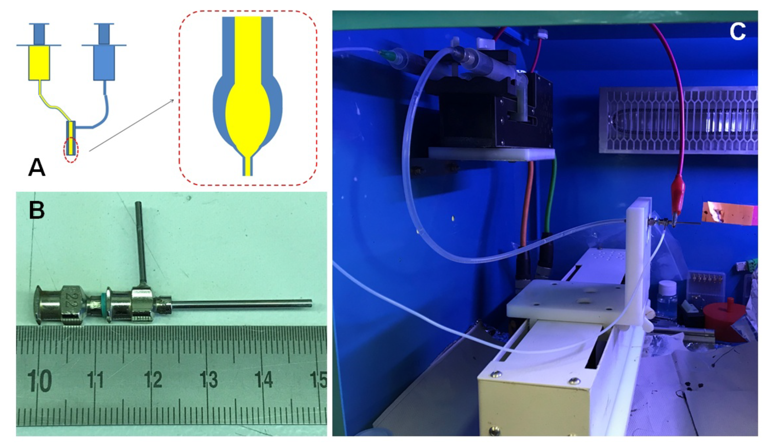
Figure 2.
A. collection setup for aligned nanowires; B. SEM image of aligned nanowires; C. approach of transporting aligned nanowires to a silicon wafer.
Figure 2.
A. collection setup for aligned nanowires; B. SEM image of aligned nanowires; C. approach of transporting aligned nanowires to a silicon wafer.
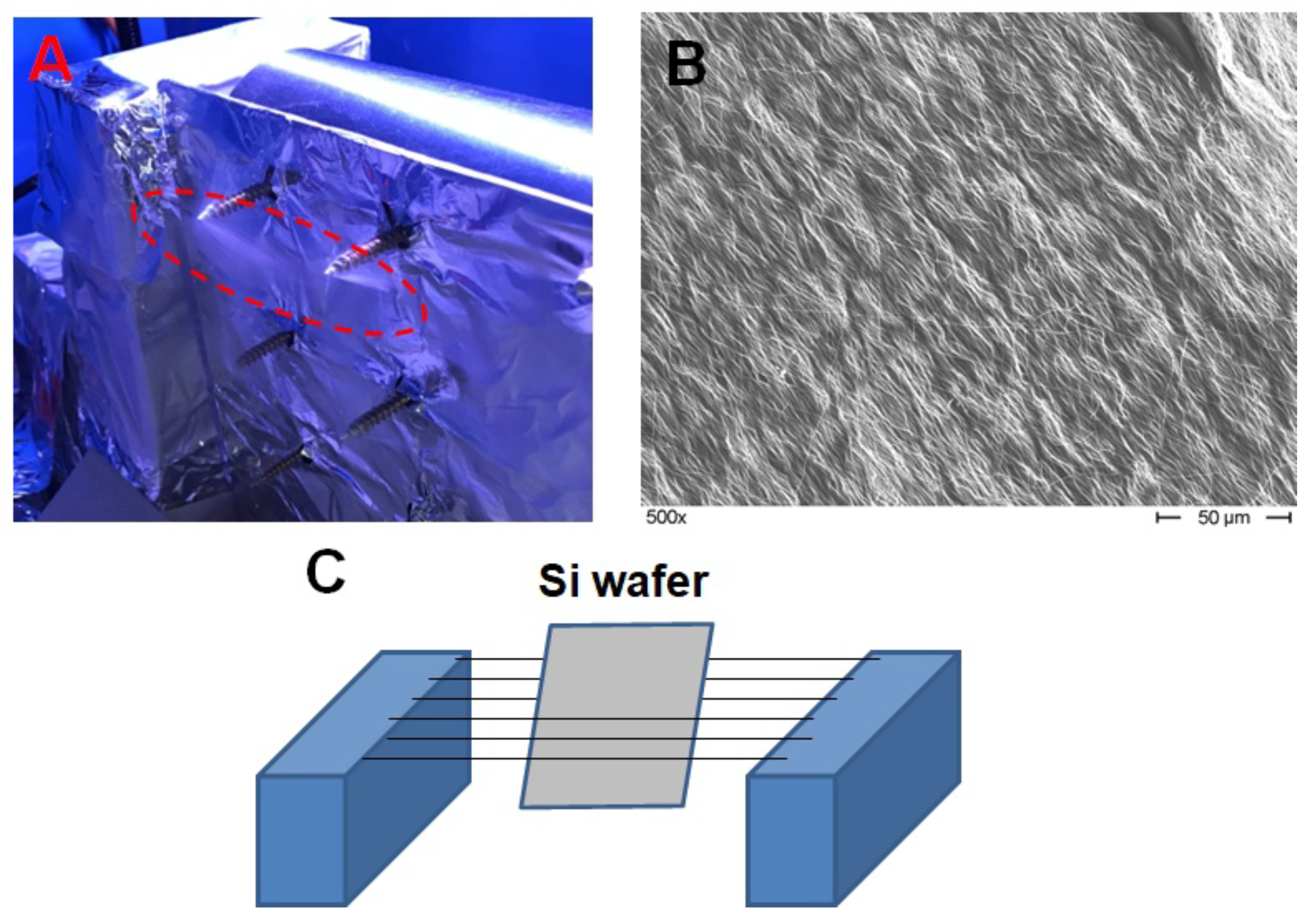
Figure 3.
SEM of the nanowire with electric pattern for magnetic impedance measurement.
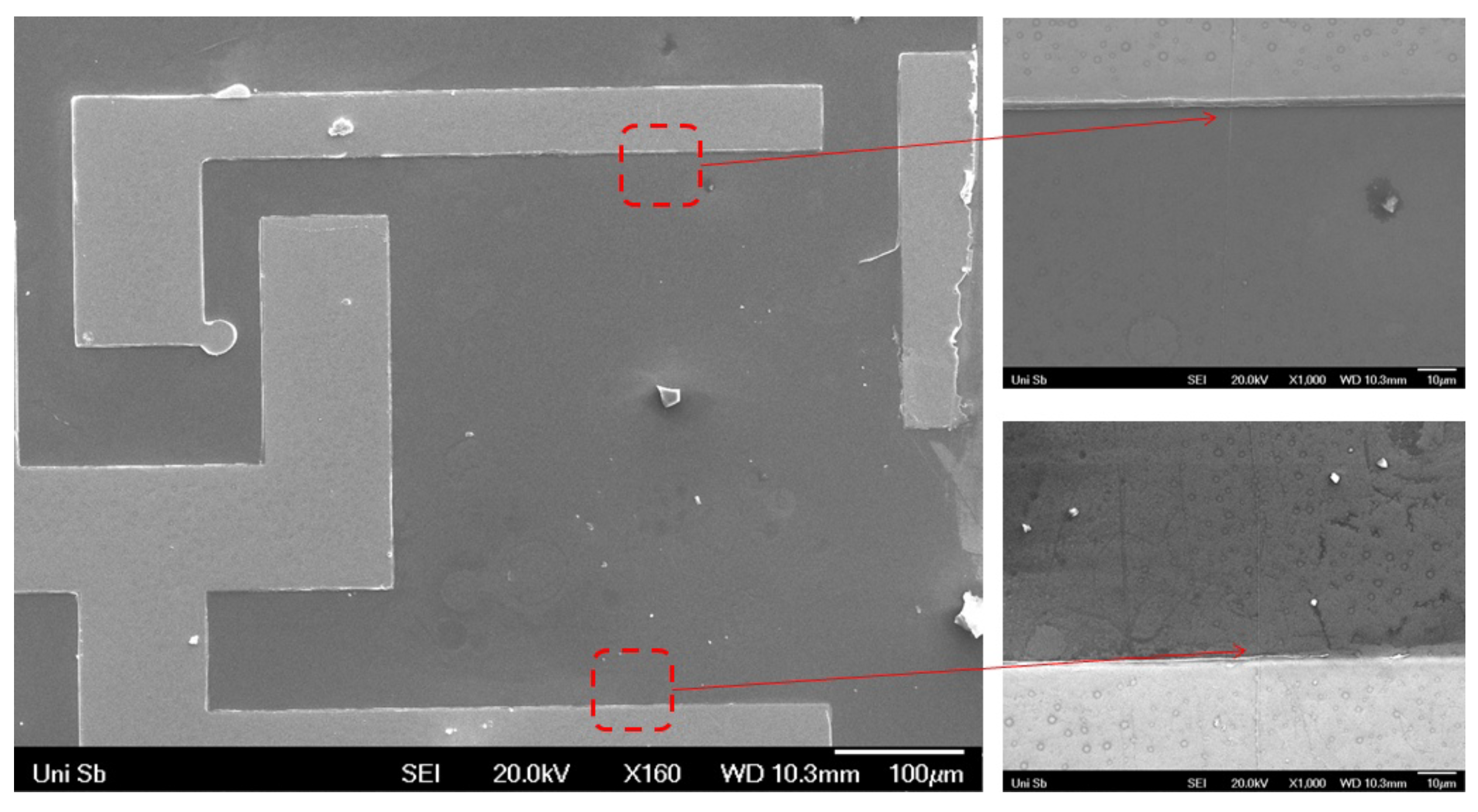
Figure 4.
A. TEM image of the BaTiO nanotubes; B. TEM image of the CoFeO@BaTiO coaxial nanowire; C. EDAX analysis of the CoFeO@BaTiO coaxial nanowire.
Figure 4.
A. TEM image of the BaTiO nanotubes; B. TEM image of the CoFeO@BaTiO coaxial nanowire; C. EDAX analysis of the CoFeO@BaTiO coaxial nanowire.
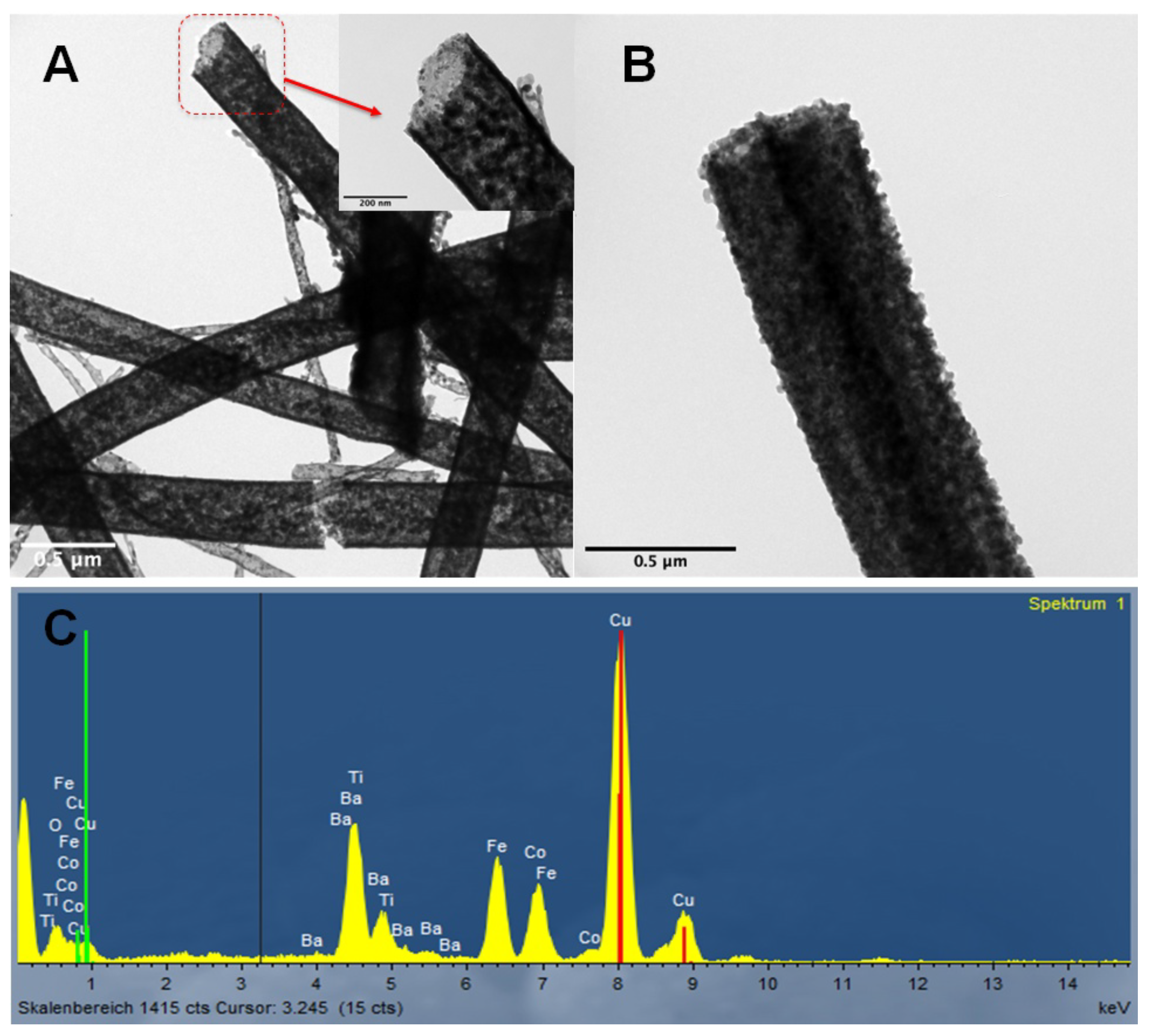
Figure 5.
XRD of the CoFeO@BaTiO coaxial nanowires with XRD refinement and phase analysis.
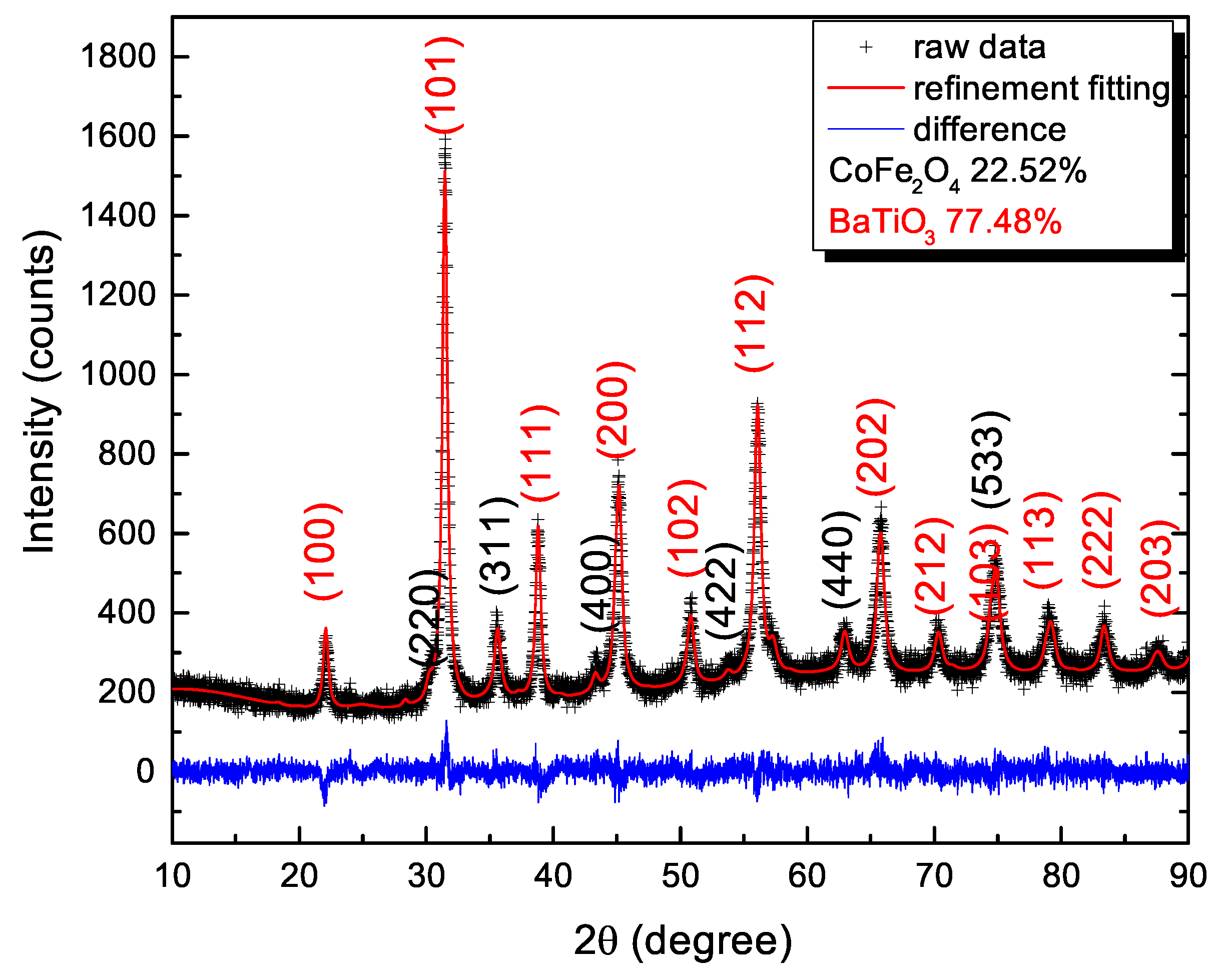
Figure 6.
M(H) magnetization of nanowires at 295 K: A. CoFeO nanowires; B. BaTiO nanotubes; C. CoFeO@BaTiO coaxial nanowires; D. BaTiO@CoFeO coaxial nanowires.
Figure 6.
M(H) magnetization of nanowires at 295 K: A. CoFeO nanowires; B. BaTiO nanotubes; C. CoFeO@BaTiO coaxial nanowires; D. BaTiO@CoFeO coaxial nanowires.
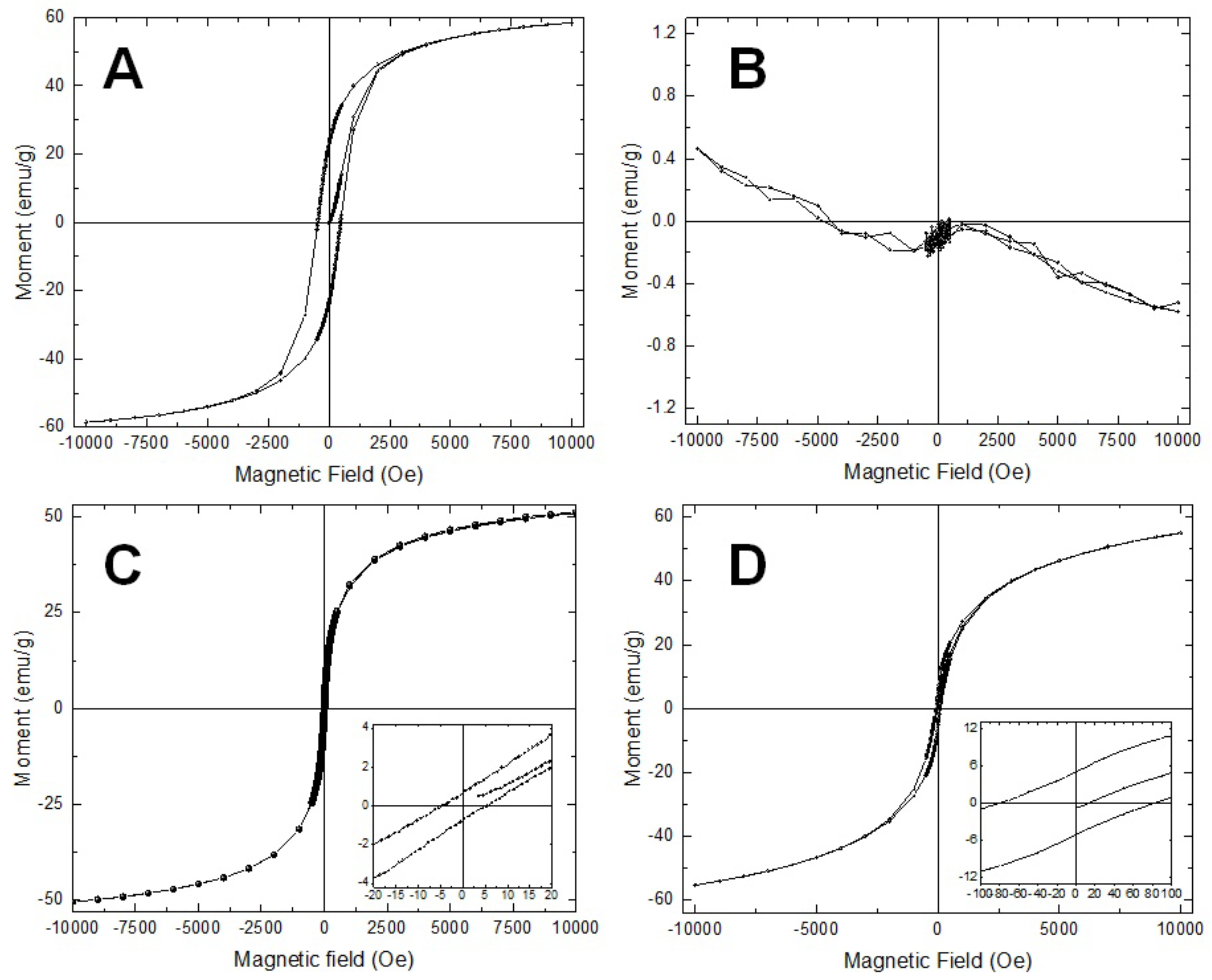
Figure 7.
M(H) magnetization of CoFeO@BaTiO coaxial nanowires with different phase ratio: A. CoFeO : BaTiO = 1 : 1; B. CoFeO : BaTiO = 2 : 1.
Figure 7.
M(H) magnetization of CoFeO@BaTiO coaxial nanowires with different phase ratio: A. CoFeO : BaTiO = 1 : 1; B. CoFeO : BaTiO = 2 : 1.
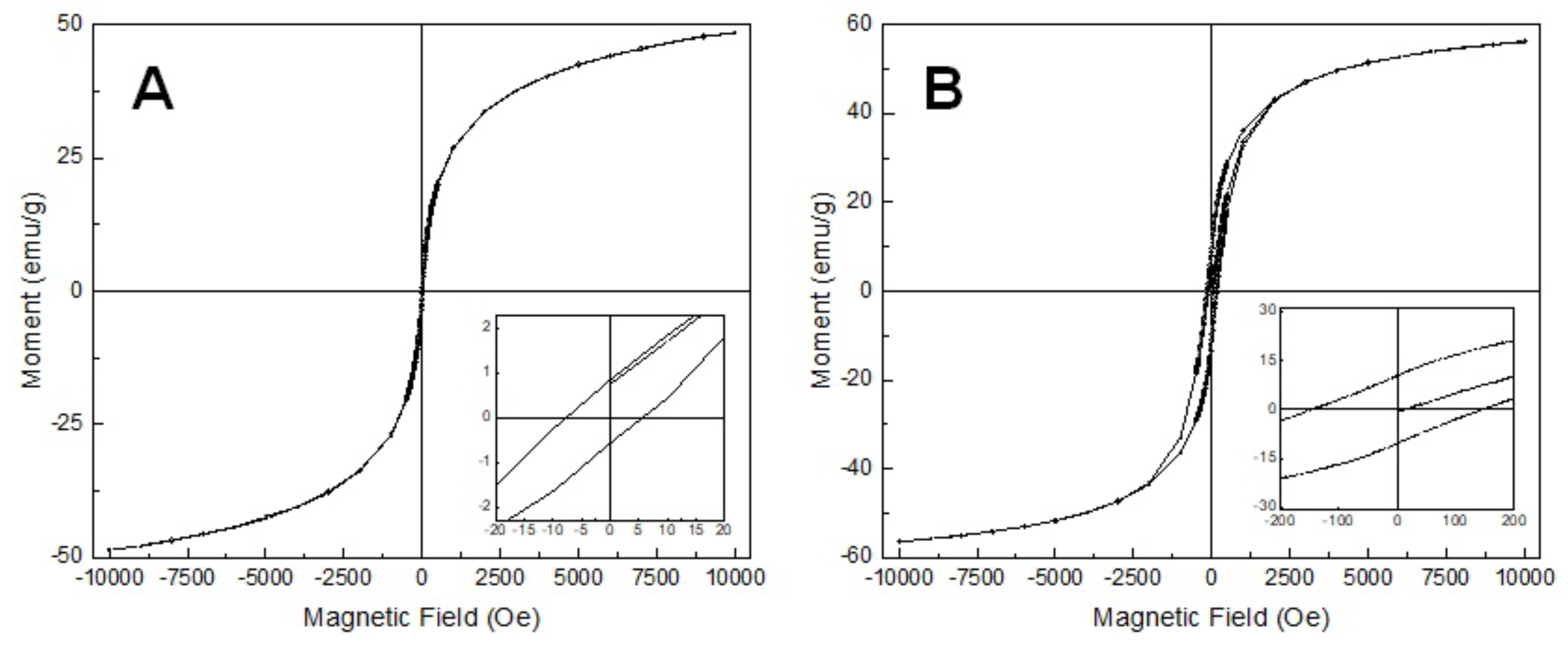
Figure 8.
A-D: M(H) magnetization of ferrite nanowires and their corresponding coaxial nanowires: A. NiFeO nanowire, B. NiFeO@BaTiO coaxial nanowires, C. FeO nanowires, D. FeO@BaTiO coaxial nanowires; E-F: M(H) magnetization of CoFeO@GdBaCuO coaxial nanowires: E: 295 K; F: 5 K.
Figure 8.
A-D: M(H) magnetization of ferrite nanowires and their corresponding coaxial nanowires: A. NiFeO nanowire, B. NiFeO@BaTiO coaxial nanowires, C. FeO nanowires, D. FeO@BaTiO coaxial nanowires; E-F: M(H) magnetization of CoFeO@GdBaCuO coaxial nanowires: E: 295 K; F: 5 K.
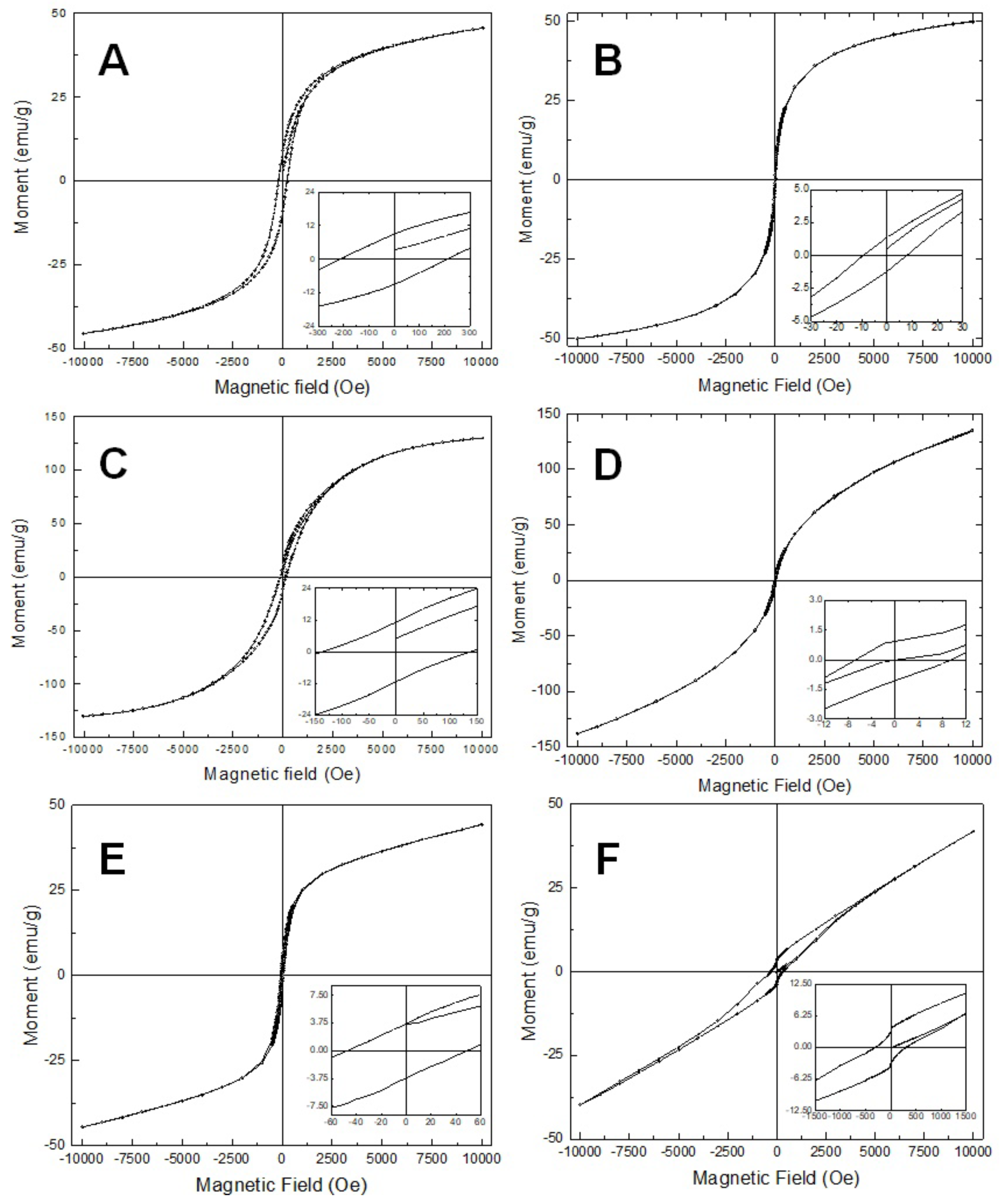
Figure 9.
A-C: Magnetic impedance measurement of the CoFeO@BaTiO coaxial nanowires: A. 10 MHz - 100 MHz, B. 100 MHz - 1 GHz, C. 1 GHz - 3 GHz; D. Maximum GMI ratio dependance on frequency.
Figure 9.
A-C: Magnetic impedance measurement of the CoFeO@BaTiO coaxial nanowires: A. 10 MHz - 100 MHz, B. 100 MHz - 1 GHz, C. 1 GHz - 3 GHz; D. Maximum GMI ratio dependance on frequency.
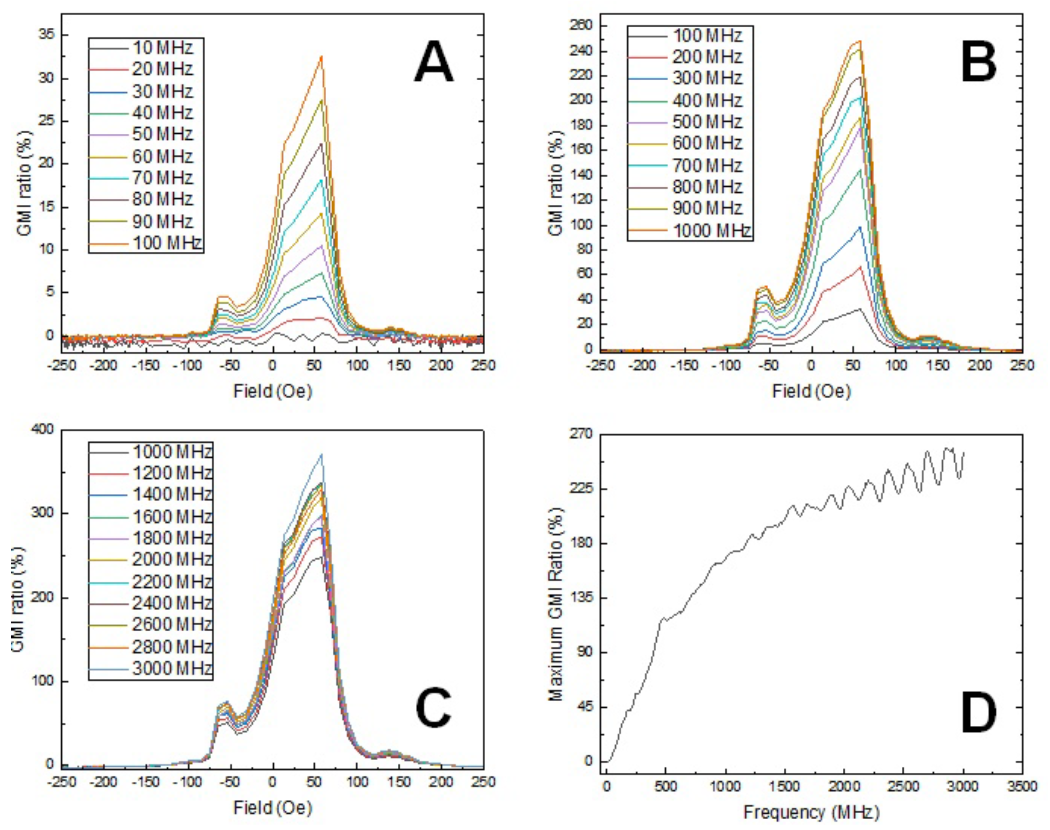

Table 1.
List of precursor recipes for the required chemical phase in this work.
| Phase | Chemicals | Molar Ratio | Solvent | ||||
|---|---|---|---|---|---|---|---|
| CoFeO | Co(Ac)4HO | Fe(NO)9HO | 1 | 2 | water | ||
| NiFeO | Ni(Ac)4HO | Fe(NO)9HO | 1 | 2 | water | ||
| FeO | Fe(NO)9HO | - | water | ||||
| BaTiO | Ba(Ac) | Ti(CHO) | 1 | 1 | Propionic acid | ||
| GdBaCuO | Gd(Ac)HO | Ba(Ac) | Cu(Ac) | 1 | 2 | 3 | Propionic acid |
Disclaimer/Publisher’s Note: The statements, opinions and data contained in all publications are solely those of the individual author(s) and contributor(s) and not of MDPI and/or the editor(s). MDPI and/or the editor(s) disclaim responsibility for any injury to people or property resulting from any ideas, methods, instructions or products referred to in the content. |
© 2023 by the authors. Licensee MDPI, Basel, Switzerland. This article is an open access article distributed under the terms and conditions of the Creative Commons Attribution (CC BY) license (http://creativecommons.org/licenses/by/4.0/).
Copyright: This open access article is published under a Creative Commons CC BY 4.0 license, which permit the free download, distribution, and reuse, provided that the author and preprint are cited in any reuse.


