Individual adjustment of the flow pattern illumination for simultaneous visualization of the shape of a rapidly deforming free surface during the formation of a cavity, a crown, a veil on its edge, as well as the registration of the drop matter position was used in each series of experiments instead of the traditional back-light illumination. The lighting technique allowed us to carry out both color and black-and-white registration of the flow pattern. To control the versatility of the proposed flow structural features classification, the spreading of uniformly colored drops of dilute solutions of alizarin ink, potassium permanganate , copper and iron sulphates, as well as tap water was studied. In all cases, the patterns of both the moving free surface and the distribution of the drop matter in a target fluid were recorded. While the overall fine flow structure was preserved, the individual properties of small elements turned out to depend on the composition of the media.
4.1. Drop Spreading of Alizarin Ink Solution in Water
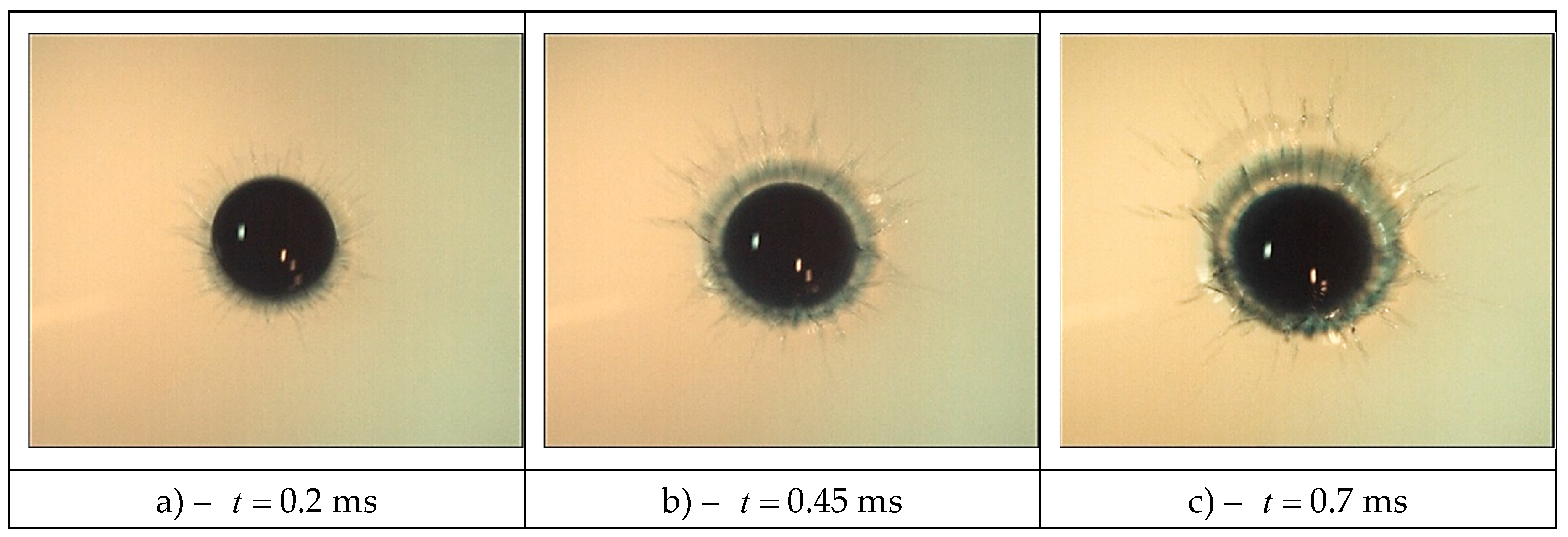
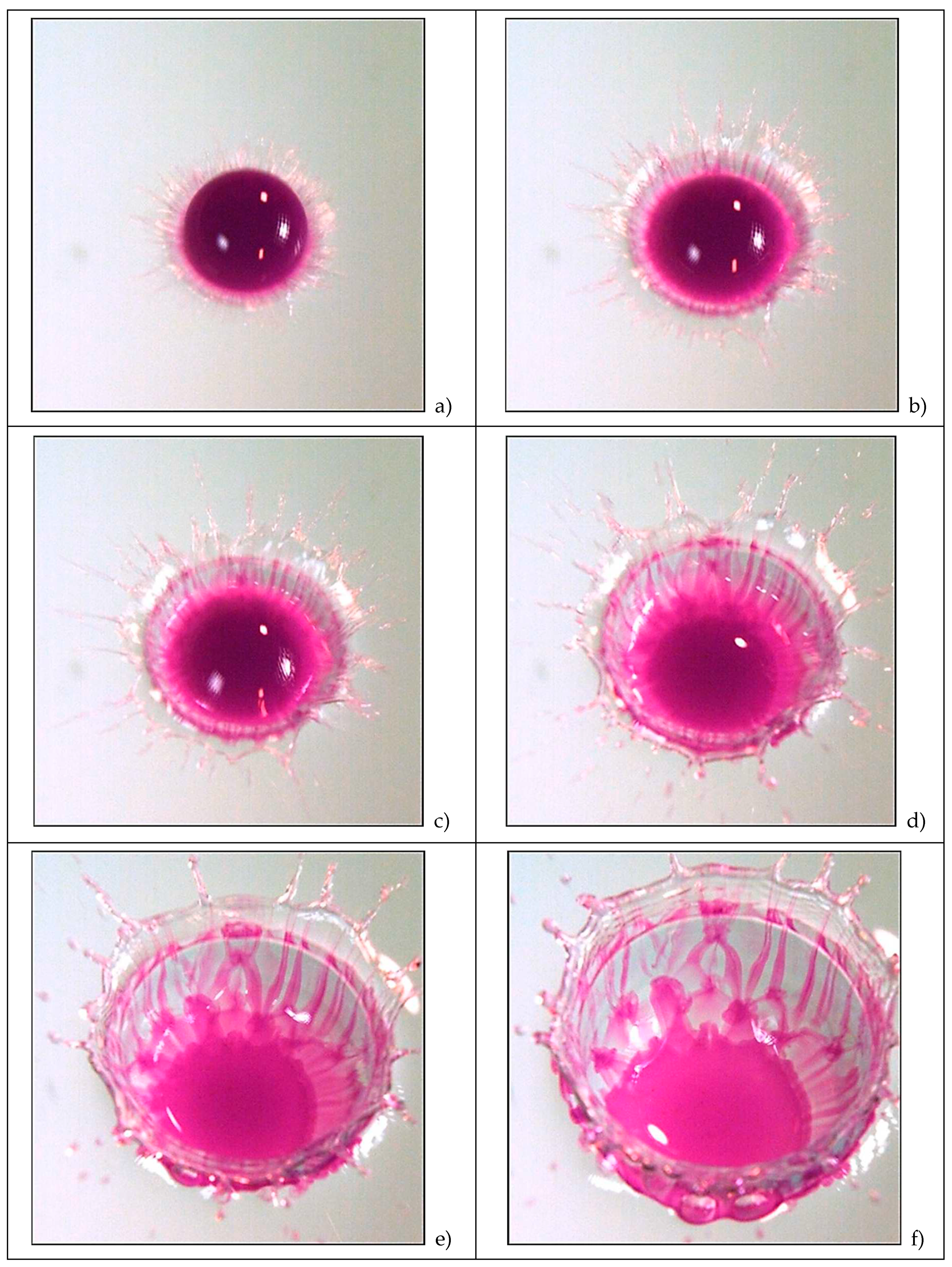
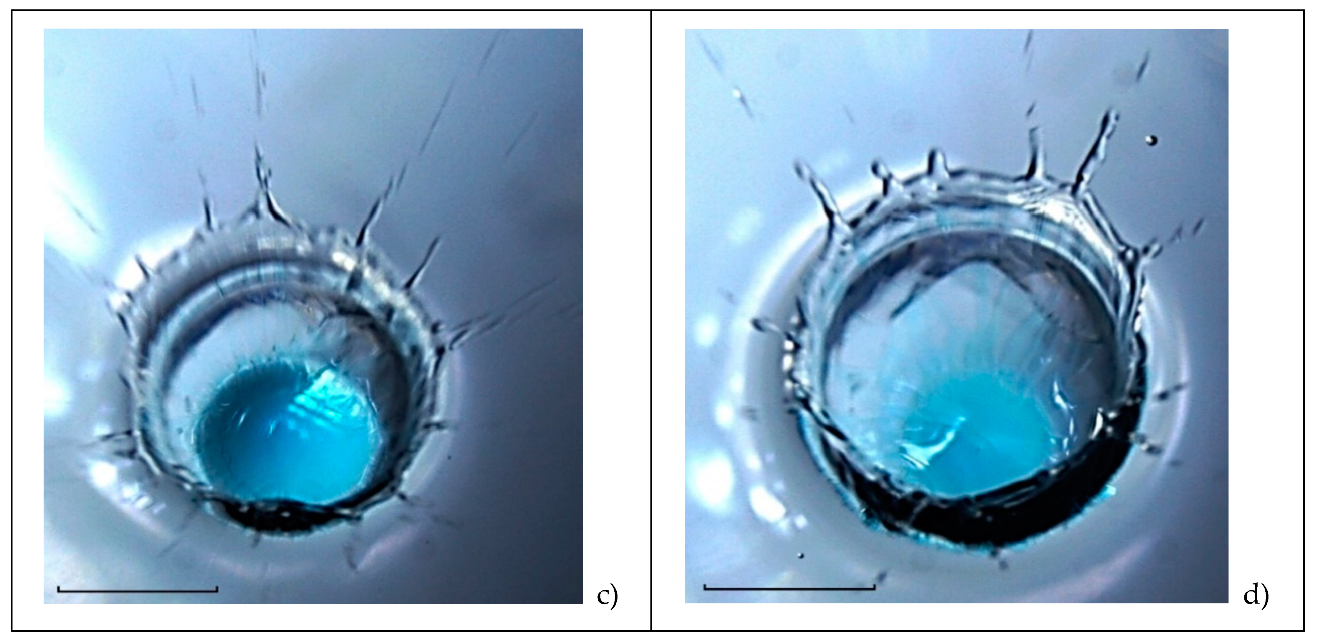
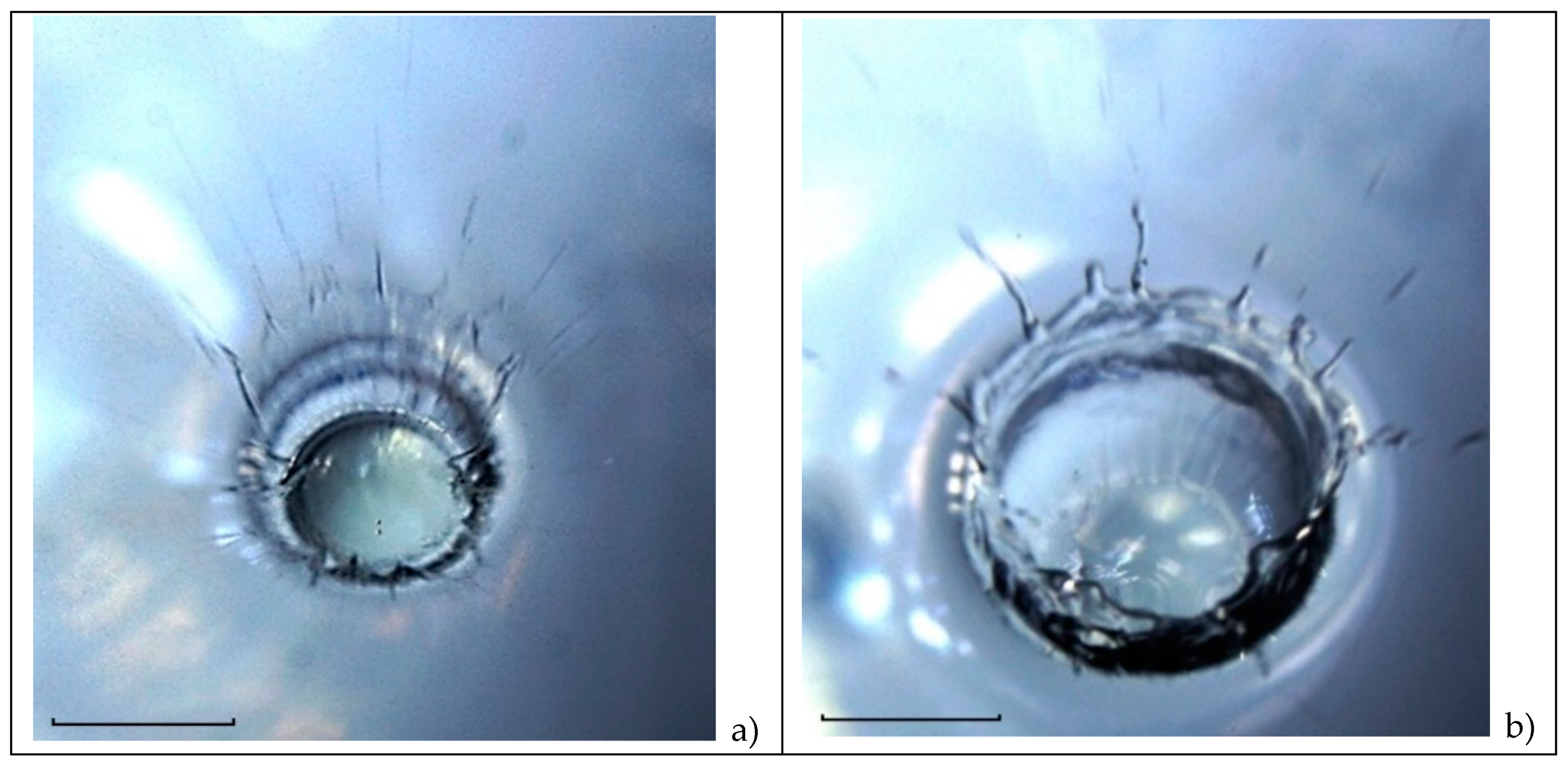
The evolution of the fine structure of the matter transfer pattern during the free-falling drop coalescence of a dilute 1:200 solution of blue alizarin ink is illustrated by the video shots shown in
Figure 2. The line of sight in these experiments is inclined at an angle
65° to the horizon. The shooting speed is 4000 fps, the shutter speed is 1/5000 s, the spatial resolution is 30 microns/pixel (µm/pix).
The primary contact of the drop is accompanied by the release of a veil (a gray strip
0.45 mm wide along the main diameter
5.6 mm), which is pierced by thin spikes. A sequence of drops is thrown from the tops of the spikes (
Figure 2,
ms). The deviation of the pattern from strict symmetry is due to the inclination of the line of sight and some asymmetry of the merging drop shape.
The length of separate jets, which are elongated traces of thrown droplets, is four times the width of the strip. In general, the trace pattern radially diverges, but some colored jets are located at an angle to the local radius vector. As it follows from the analysis of variations in the illumination distribution pattern along an arc 0.2 mm away from the contact line, the thickness of the droplet traces is 50 microns, the length reaches 1.8 mm, the inclination angle from the direction of the local radius vector lies in the range . The dispersion of the angular positions of the spray trajectories can be caused by variations in the angle between the shells of the veil edge in the vicinity of the spike from which the small sprays are thrown out.
The general asymmetry of the flow pattern is because of the difference in the shape of the incoming drop and the spherical one due to Rayleigh oscillations and capillary waves traveling along its surface [
45]. The general gray background of the veil and darker lines, which are traces of the thrown liquid layer and single ligaments (thin jets that arise at the contact line of the drop with the target liquid) indicate the complexity of the emerging flow pattern. It expresses both two-dimensional continuous veil and fast spikes that are three-dimensional components.
The ratios of the sizes (length and diameter) of individual strokes which are the extensions of spikes (blurred images of thrown droplets (their velocity is
m/s)), show that their velocity noticeably exceeds the drop velocity [
46]. The rapid flow of liquid in the jets is provided by additional energy released when the free surface of the merging liquids is eliminated. This energy is transformed into other forms, including the energy of mechanical motion.
As the drop coalescence, the flow pattern, in which one can distinguish the veil in the upper left part and the crown, becomes more complicated (
Figure 2b,
0.45 ms). The visible edge of the tinted domain (the trace of the drop residue) loses its smoothness. Colored fibers come out of individual protrusions, which spread at the cavity bottom, go through the crown wall and the veil forming spikes on its outer border. The continuity of the jet traces (linear elements of the flow geometry) indicates the structural stability of the developing flow. Jets are formed at the initial coalescence phase and persist for a long time.
The radial inhomogeneity of the image brightness allows to confidently identifying at 0.45 ms the individual flow components. They include the drop residue with a diameter of 4.74 mm and the cavity bottom. A dark circular line is the inner boundary of the crown wall; the circular boundary line is the crown outer edge, which is continuing by veil. The outer edge of veil is tightening and thickening; individual fibers on its surface and their extensions that are spikes coming out from the tops of the teeth. Strokes, which proceed the spikes, are traces of fast flying sprays.
The jet traces (dark fibers) are adjacent to the protrusions at the visible contact boundary of the drop residue and the deepening cavity. The slope of the cavity bottom explains some clarity loss of the image of the crown moving borders and the drop residue spreading along the cavern bottom. However, here the extension of jet traces connecting the spikes on the veil edge with the boundary of the drop residue is well traced.
As the flow evolves, the diameter of the central spot slowly grows (the drop remnant spreads along the cavity bottom). At the same time, the adhesion of the colored fibers to the boundary of the merging liquids is more and more clearly expressed (
Figure 2c,
0.7 ms).
As the flow evolves, the diameter of the central spot slowly grows (the drop spreads along the cavity bottom). At the same time, the contact of the colored fibers to the boundary of the merging liquids is more and more clearly expressed (
Figure 2c,
0.7 ms).
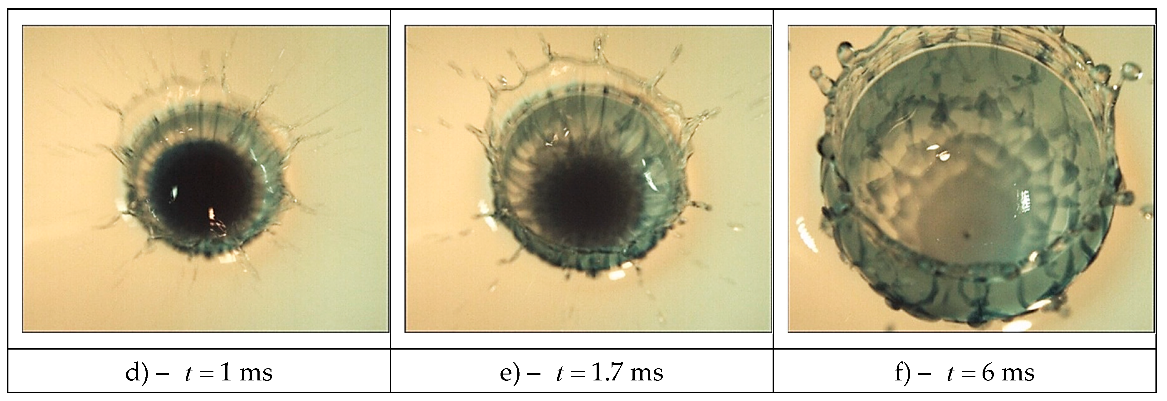
As the drop sinks, the sizes of the crown and the cavity grow. The diameter of the droplet residue (the central undisturbed spot) decreases somewhat due to the formation of new tiers at its edge of a discrete distribution pattern of the droplet matter (
Figure 2d, 1 ms). The boundary between the drop residue and the cavity bottom becomes more and more indented and thickened. There are separate protrusions on it – analogs of spikes on the veil edge in the air. Over time, the diameters of the protrusions grow, the contrast decreases.
The elements of the fibrous reticular structure are traced inside the tinted central spot with a diameter of
5.45 mm at
1.7 ms. Gradually, the linear structure on the outer cavity boundary is replaced by a reticular one, at
6 ms triangular cells appear on the crown walls (
Figure 2f). Five tiers of cells are allocated inside the cavity.
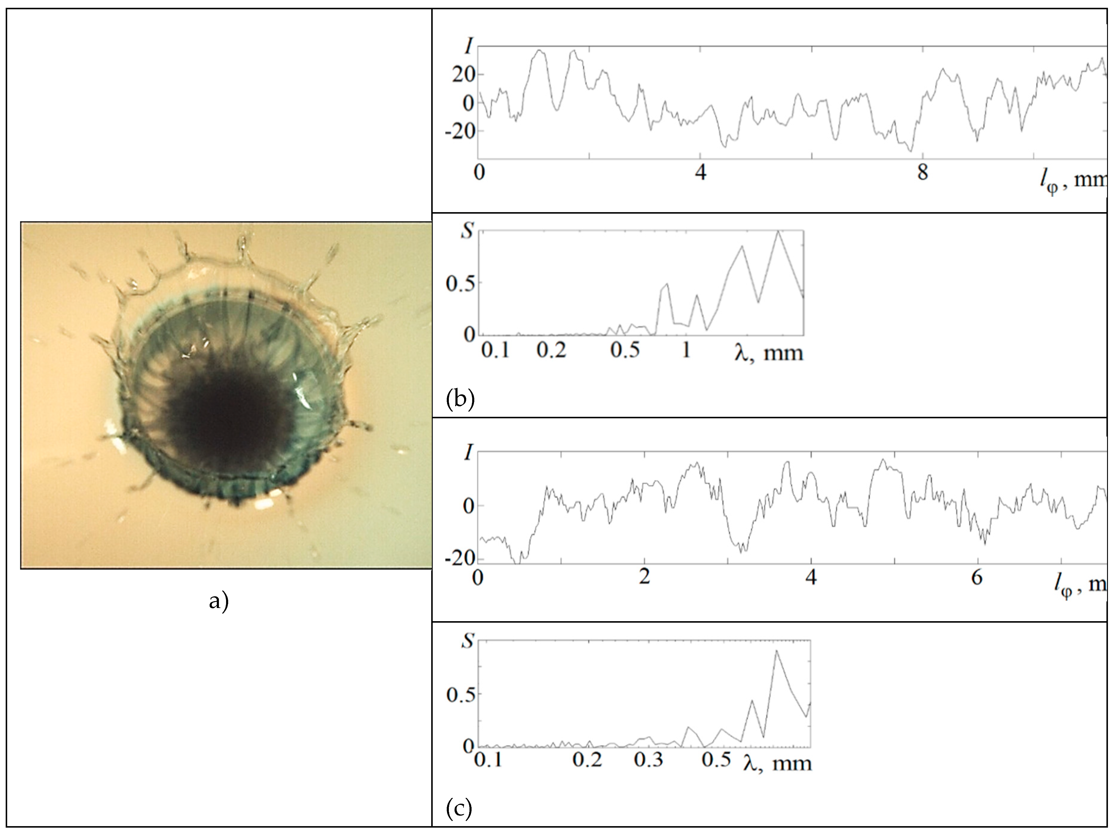
The photometry results of the relative flow pattern illumination are presented in
Figure 2e at 1.7 ms and the dependence of the relative energy spectrum
on the scale
is shown in
Figure 3. The illumination values
are determined in a circular spot with a diameter
30 µm, which moves a distance
along the arcs of circles with a radius
3.15 and 2.6 mm.
In the middle of the cavity sidewall at 3.15mm, where linear structures in the distribution of the drop matter are distinguished, the peaks on the spectrum correspond to scales 0.42, 0.47, 0.54, 0.63 and 0.8 mm. In the transition zone between the drop residue and the cavity bottom at 2.6 mm, where reticular structures with triangular cells are traced, the peaks at scales 0.39, 0.49, 0.6, 0.71 mm are distinguished in the spectrum. The smallest scales characterize the thickness of single fibers.
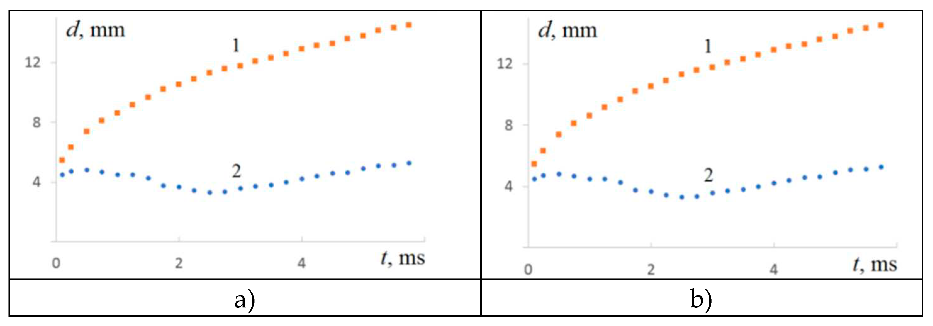
Figure 4.
The evolution of the coalescence domain parameters of a drop of ink solution with water: a) – the diameters of the crown and the central spot – curves 1 and 2; b) – changes in illumination in the center of the flow in a circle with a diameter 0.8 mm.
Figure 4.
The evolution of the coalescence domain parameters of a drop of ink solution with water: a) – the diameters of the crown and the central spot – curves 1 and 2; b) – changes in illumination in the center of the flow in a circle with a diameter 0.8 mm.
The change in the rate is explained by the complexity of competing diffusion and hydrodynamic processes occurring in the intermediate layer under the cavity bottom. The dark spot in the center of the flow at
6 ms is the trace of a growing jet with a vortex head under the bottom cavity center, which has been visualized earlier [
48]. With further evolution, the protrusions on the sidewall of the cavity also transform into jets, which form elongated colored loops when the cavity collapses.
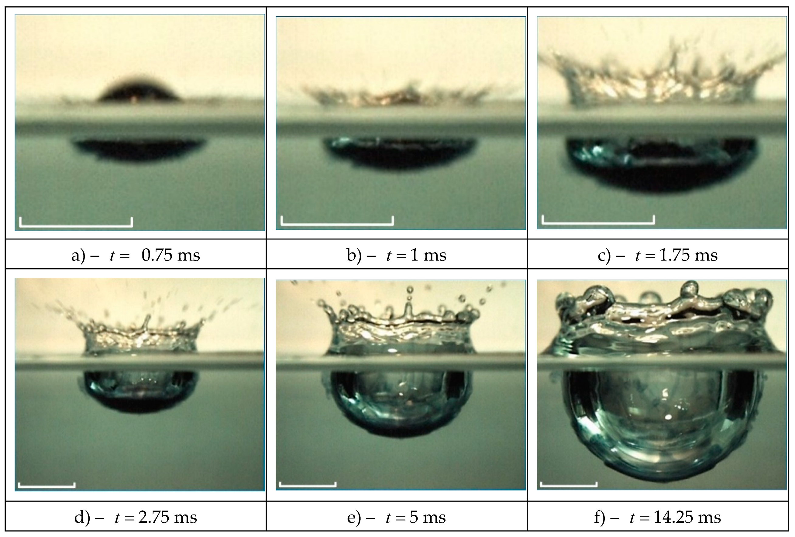
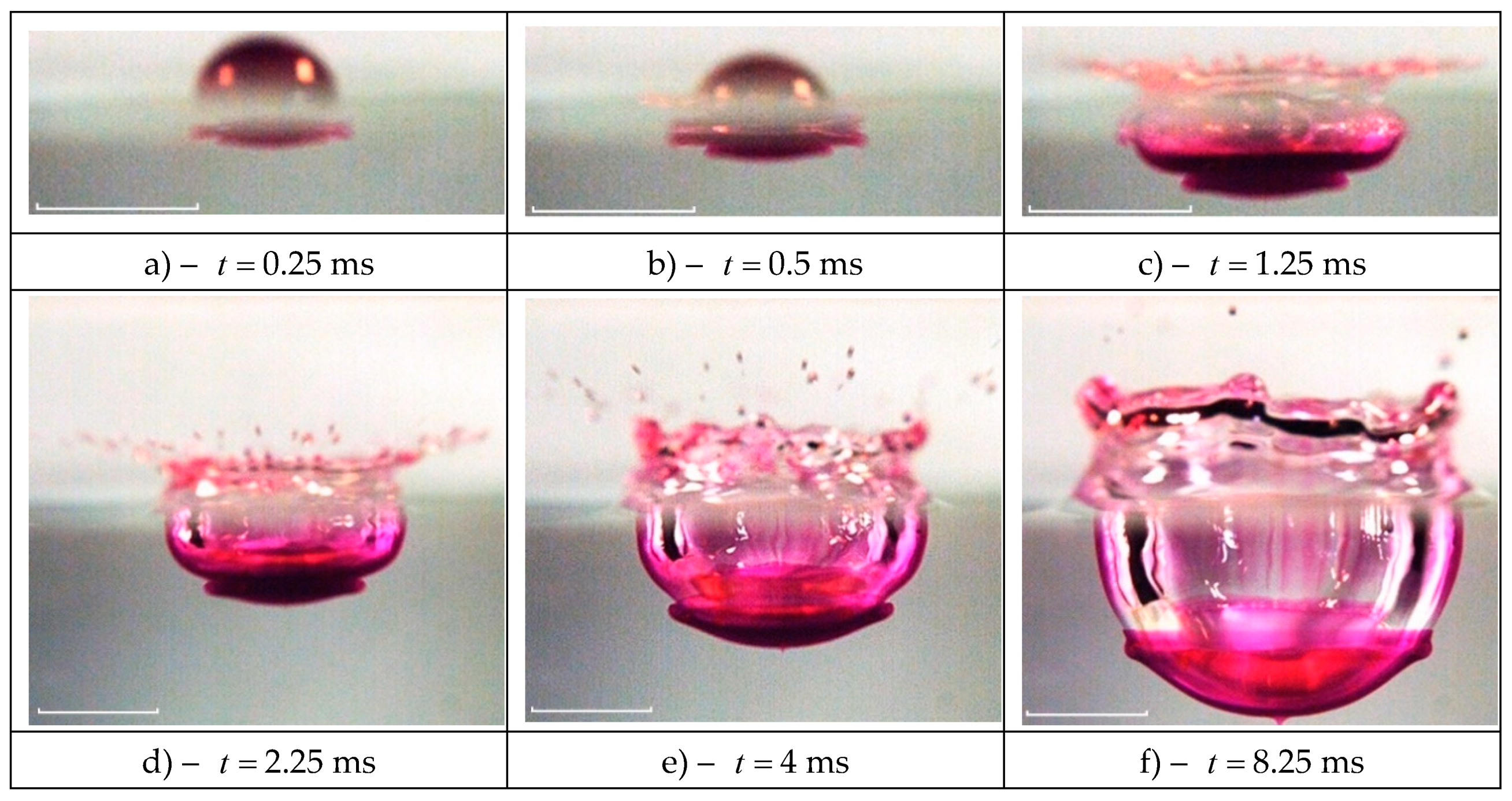
The pattern features of a drop spreading, colored with blue alizarin ink, in the fluid thickness are illustrated by frames from the video of the flow pattern in the lateral projection shown in
Figure 5. Drops begin to deform the free fluid surface, creating a cavity, from the moment of the initial contact. At the same time, the drop liquid leaks in thin jets through the cavity bottom and forms an intermediate layer in which the fibers of the colored liquid are separated by interfaces of the target fluid (water in these experiments) [
49].
In the first shot of the flow pattern in the lateral projection shown in
Figure 5a, a dark strip with a flat bottom
5.6 mm in diameter, and
0.56 mm in height, adjacent to the free surface, visualizes the cavity partially covered with droplet liquid fibers. Adjacent to the cavity from below is a growing intermediate layer with diameter
3.5 mm and height
0.4 mm, formed by fibers containing a drop matter` that have passed through the cavity bottom. The fibers grow perpendicular to the cavity bottom at the initial stage of the coalescence process, when the size of the contact domain of liquids increases rapidly. In this case, the free surfaces of the contacting liquids are eliminated with the simultaneous conversion of APSE into other forms, causing the formation of thin jets. The visualization of the intermediate layer at the later stages of droplet spreading is given in [
44], its thickness is measured in [
47].
The fibrous structure of the flow pattern, which is presented along the entire boundary of the intermediate layer, is more clearly expressed on its lower edge in
Figure 5b. In the upper part of the cavity with diameter
6.12 mm and depth
0.96 mm, a air cavity with thickness
0.5 mm is visible. An intermediate layer with diameter
3.9 mm and thickness
0.44 mm adjoins the cavity from below.
As the cavity grows, the intermediate layer on its lower edge becomes thinner, its outer border is leveled (
Figure 5c). Here, the main part of the droplet substance is concentrated in the lower part of the cavity in a layer
0.6 mm high, including an advanced intermediate layer. Examination of the enlarged image shows that the lower part of the cavity is densely covered with colored liquid droplets, and in the upper part, single colored fibers are distinguished.
Further, the intermediate layer becomes much thinner and covers the cavity surface with diameter
8.7 mm with a thin layer (up to
0.3 mm thick,
Figure 5d). The cavity height with an intermediate layer is
3.42 mm. Here the intermediate layer is distributed more evenly along the cavity bottom, its thickness does not exceed
0.4 mm. In a densely colored domain, the droplet matter is collected in the lower part of the cavity in a
0.9 mm high layer. At the upper edge of the intermediate layer, the surface is tinted most densely. Crests and troughs
2 mm in size are traced on the border of the tinted layer.
After the crown reaches its maximum size (the height is
3.7 mm, the diameter is
11.3 mm) and begins to decline, the capillary waves propagate down from its upper edge. The shape of the phase surfaces of waves replicates the changing contour of the edge crown. As the cavity deepens further, the concentration of the drop pigment becomes more and more aligned in height (
Figure 5e). Gradually, the pigment flows down, the side wall of the cavity become sufficiently transparent and vertical fibers are displayed on them (
Figure 5d). At the same time, the lower edge of the intermediate layer begins to lose its smoothness again, protrusions and troughs appear in it. They are caused by the flow of coloured fluid along the fibers, by accumulation in the reticular formation nodes, pushing through the cavity surface and the formation of small vortices [
48]. At the same time, the crown edge is rounded, capillary waves cover its entire surface.
The release of droplets from the tops of the spikes on the crown surface ceases over time, only their rounded remnants persist (
Figure 5f,
14.25 ms). The inner surface of the cavity is covered with individual fibers and spots containing droplet matter. The intermediate layer on the outer surface of the cavity also loses its homogeneity, individual brightly colored domains appear in it.
The study of color flow patterns allows distinguish between the processes of deformation of the liquid surface forming a cavity and a crown, and the processes of droplet matter transfer. The fibers containing the droplet matter leak through the deformed boundary of the cavity and form a finely structured layer under the cavity bottom in the thickness of the target fluid. Gradually, diffusion aligns out the heterogeneity of the droplet pigment distribution and a uniformly colored intermediate layer is formed under the cavity bottom. In the frontal projection, it corresponds to a more densely colored spot in the flow center. Over time, the thickness and size of the spot, its shape, undergo significant changes due to the size and shape alteration of the cavity, the fluid flow in thin jets forming linear and reticular structures on the cavity inner surface.
4.2. Drop Spreading of Potassium Permanganate Solution in Water
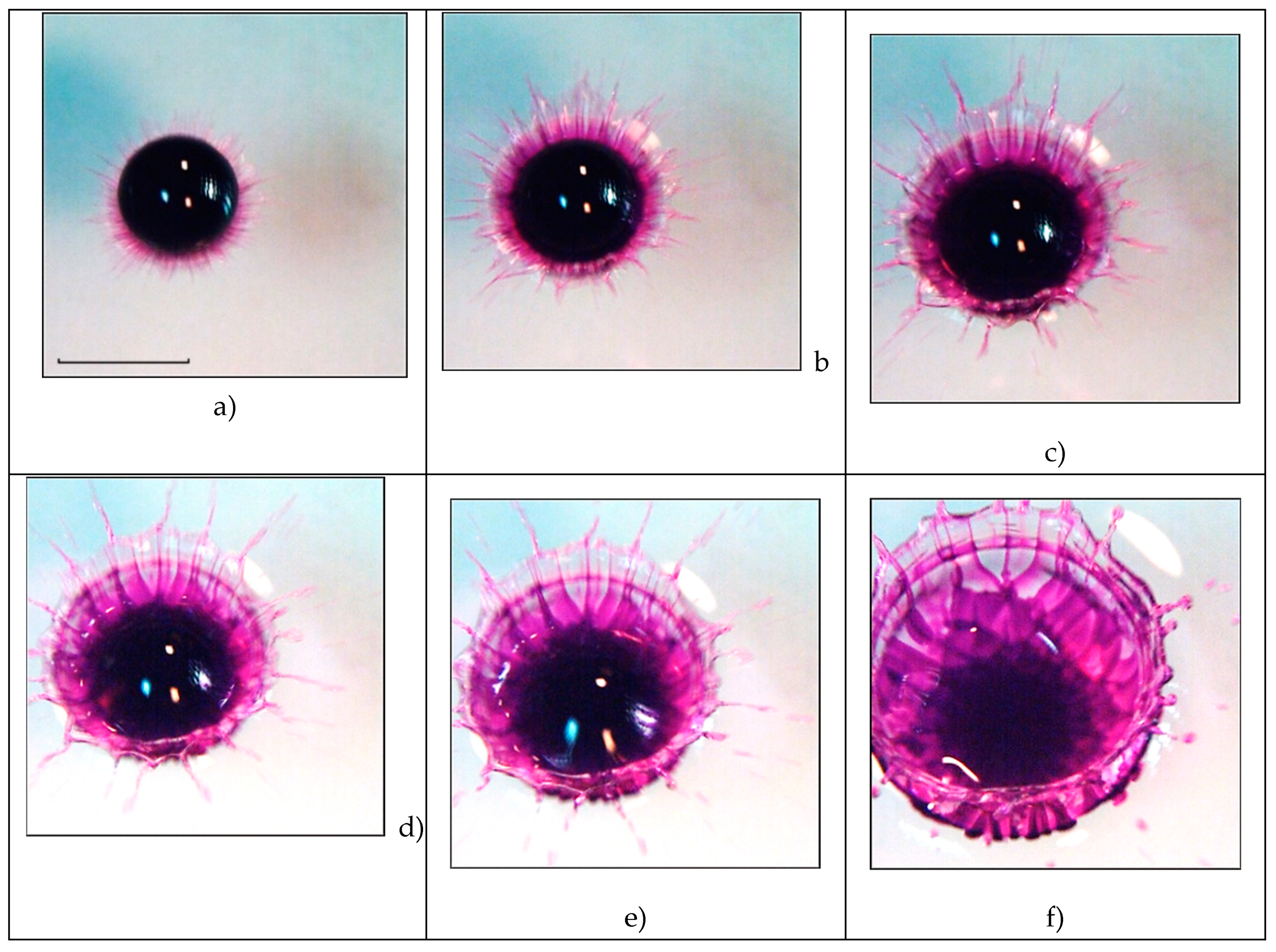
The video shots of the drop coalescence of dilute potassium permanganate solution with water are presented in
Figure 6 (the inclination of the line of sight is
65° to the horizon, the shooting speed is 4000 fps). When the chemical composition of the merging liquids changes, the general flow structure is preserved, but the parameters of the thin components change noticeably. The outer ring of the flow at the initial droplet contact consists of individual spikes
~ 0.1 mm thick and
mm long, partially tinted with pigment droplets (
Figure 6a,
0.25 ms).
The spikes are in contact with the edge of a thin, weakly colored light circular veil with a width
= 0.57mm, in which thin brightly colored jets
0.1 mm are traced. They form a rather regular linear structure, which has been repeatedly observed in experiments with other substances [
18]. Large splashes of light allow to consider the veil surface as a continuous relatively smooth surface.
The veil is adjacent to a darker wide ring 0.2 mm visualizing a growing crown. A brightly colored strip with a width =0.18 mm is a growing cavity in contact with a drop residue =4.5 mm in diameter. The examination of the enlarged image shows that colored fibers protrude from under the drop and continuously last in the cavity, crown, and veil. They form the core of a thin jet, which is a spike protruding from the crown edge. Thus, the flow of the spreading droplet has a predominantly radial direction.
The flow structure is preserved in the next shot at 0.5 ms. The dimensions of the above-mentioned structural components have grown: they are 0.15 mm and mm for the thickness and length of the spikes, mm for the veil, mm for the crown and 0.36 mm for the cavity. The diameter of the drop residue (a dark area with an uneven edge), the protrusions of which are adjacent to the colored fibers, is 4.26 m. The outer edge of the veil becomes more indented, the number of spikes increases (in the first frame you can count 17, in the second one – 19 teeth in the upper semicircle).
Over time, the clarity of the fiber pattern at the bottom of the cavity remains, which becomes more and more densely colored (
Figure 6c). At the same time, the boundary between the cavity bottom and the drop residue with diameter
4.33 mm becomes increasingly indented. The preservation of the continuity of the colored fibers indicates the immutability of their angular position in the moving contact domain of the merging fluids.
As the crown width increases and the cavity deepens, the velocity of the colored jets decreases, the protrusions in the edge contour of the cavity deepen, the spikes break up into sequences of individual droplets, the diameter of which grows over time (
Figure 6d). A reticular pattern of individual fibers is visible under the colored drop liquid floating to the cavity bottom. The uneven boundary of the central spot shifts slightly to the flow center –
4.6 mm.
As the cavity deepens and the crown expands, the contrast of the fibers decreases, the width of which increases (
Figure 6e,
2.25 ms). A fracture in the angular position of the fibers indicates a sharp change in the inclination of the cavity walls, at the bottom of which the contours of the emerging reticular structure of the fibers are traced in a diffusely colored layer. In the drop residue, a densely colored core and a diffuse outer part are distinguished. The fibers move to the protrusions of its boundary. The extensions of the fibers are traced on the cavity walls, the remnants of the veil, spikes and ejected splashes. The outer part of the cavity sidewall, visible in the lower part of the figure, loses its smoothness. Jets begin to bulge on it, gradually transforming into fibrous loops when the cavity collapses [
48].
After a while, the contrast of the fibers is decreasing, their width is increasing (
Figure 6f). The color of the flow central domain becomes more uniform. The inhomogeneity of the outer boundary contour of the drop residue is preserved in the right part of the figure, where the fibers are visualized along the entire length. In general, the pattern of fiber distribution is being rebuilt, its elements are being enlarged.
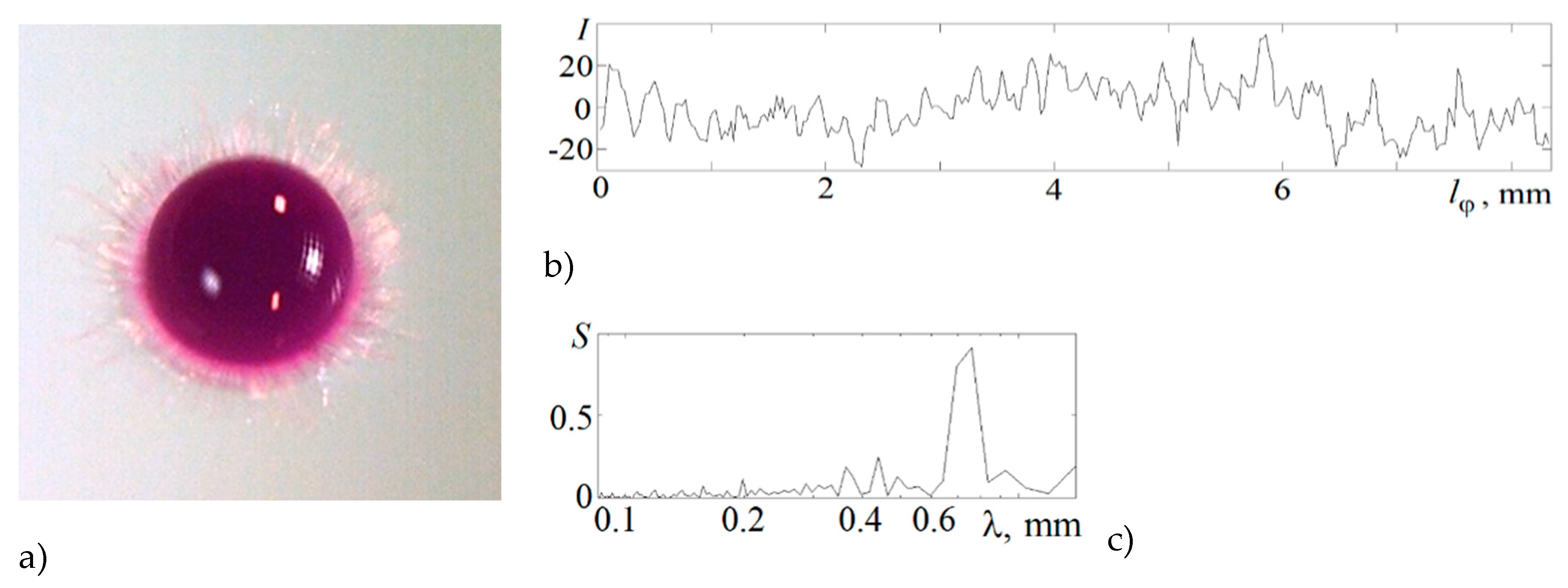
In the energy spectrum
of the distribution of the relative illumination flow pattern
along a circle with a radius
2.75 mm in the upper half-ring shown in
Figure 7 at
1.7 ms, the peaks at scales
0.2, 0.37, 0.44, 0.76 mm are distinguished. The smallest scales characterize the thickness of individual fibers.
The peculiarities of the droplet matter transfer in the impact coalescence mode are explained by samples from the video film of the flow pattern in the vertical plane (
Figure 8, side view image). At the initial stage of droplet coalescence, the flat bottom of the cavity is penetrated by thin fibers separated by interfaces of the target fluid. A fibrous layer of diameter
3.44 mm and height
0.3 mm with an uneven lower edge adjoins a flat brightly colored bottom of a growing cavity with width
4.83 mm and height
0.52 mm (
Figure 8a). The cavity quickly deepens, and at
0.5 ms, a gas cavity with width
3.3 mm and height
0.25 mm begins to be visible through the colored wall. The total height of the cavity is
0.55 mm. The growth of the size of the fibrous layer adjacent to the cavity bottom slows down, and at
0.5 ms its width is
4 mm and height is
0.42 mm.
All the traditional components of the flow – a cavity, a growing crown with spikes and a spray cloud are shown in
Figure 8c. The diameter and overall height of the cavity with a brightly colored lower layer is
8.2 mm and the height is
1.3 mm. The dimensions of the adjacent fibrous layer are
5.24 m and
0.77 mm at
1.25 ms in
Figure 8c. The inhomogeneities of the pigment distribution begin to smooth out quickly by the processes of molecular diffusion in the intermediate layer under the cavity bottom (
10.3 mm and the height
3.13 mm in
Figure 8d). Here on the side walls of the cavity, the bottom of which is gradually deformed from flat to convex, vertical fibers are viewed.
Further, the rapidly deepening cavity bottom "pushes apart" and throws the remnants of the intermediate layer, the boundaries of which can still be identified at
4 ms (
Figure 8e). The crown begins to fall off, the capillary waves appear at its edge.
The cavity takes a shape close to spherical at
8.25 ms (
Figure 8f). A system of vertical fibers remains on its side surface. The crown walls are covered with capillary waves. An intermediate layer
0.3 mm thick and
3.86 mm high covers the entire cavity bottom with an even layer. The exception is its center, where a thin jet begins to grow [
47]. The measurements of the thickness of the intermediate layer were carried out in [
47] by an optical method implementing longitudinal chromatic dispersion.
The three-dimensional structure of the flow in the contact domain of the merging liquids includes thin flat jets running along the cavity bottom to the spikes on the crown edge, and even thinner fibers penetrating the cavity bottom, which form an intermediate layer. At the initial stage, the liquid interface alternately passes along the tops of the fibers with the drop pigment, then it "jumps" to the tops of the layers of the target liquid separating the colored fibers. That is., in some domains it passes along the outer boundary of the fibrous intermediate layer, and in neighboring domains it passes along the inner one. Qualitatively, we can assume that at the bottom of the growing cavity, the boundary of the coalescence region has a complex three-dimensional piecewise smooth shape.
A sample of shots from the video of the coalescence of a solution of potassium permanganate of higher density, shown in
Figure 9 indicates the scenario stability of the appearance of new components of the flow pattern and illustrates some subtle details of the flow pattern more clearly. The bright color of the spikes with splash droplets flying from their tops confirms the tendency of the rapid flow of the drop pigmented fluid. The velocity of the first splashes in these experiments, which is
5.6 m/s, noticeably exceeds the drop velocity
3.5 m/s (
Figure 9a,b).
The inflow of additional energy, which ensures the rapid flow in spikes and sprays, is provided by the processes of APSE conversion in a thin layer of merging near-surface layers contact [
26,
36]. The length of the spikes does not exceed
2.7 mm, their thickness is
0.1 mm. A colored disk
0.4 mm wide between the annular line of coalescence of the drop residue with the target fluid and the growing wall of the cavity and crown is the forming bottom of the cavity with a diameter of
5 mm. The diameter of the crown edge reaches
7 mm at the same time.
The number of spikes decreases with time. Some of them are completely separated from the veil edge. A trough forms in such places (
Figure 9c). The heterogeneity of the shape of teeth and spikes indicates the complex three-dimensional nature of fluid flows in the veil. One part of the spikes serves as the continuation of the brightly colored traces of ligaments. The other part is formed as a result of the coalescence of a pair of jets, reaching the thickness of 0.2 mm.
Protrusions up to 1 mm long are observed at the border of a densely colored domain in the center of the flows. Fast trickles flow out from their tops (
Figure 9d). Gradually, as the intermediate layer spreads under the cavity bottom (
Figure 9e,f), the background color of the cavity walls becomes more uniform. Triangular elements appear in the flow structure. The heights of the tiers is
0.88, 1.24, 1.67 mm with the thickness of the forming fibers from
mm. They are most clearly expressed in the upper part of the cavity, in the vicinity of the transition domain where the cavity transfers into the crown rising above the level of the undisturbed surface (
Figure 9e).
As the cavity and crown grow, the number of triangular grid cells on the bottom and walls of the cavern increases, and boundaries appear in their structure separating ring sets of cells (
Figure 9f). The outer border of the cavity loses its smoothness at the bottom of the image. Here, colored sections of fibers begin to be squeezed into the transparent target liquid, the further evolution of which is traced in [
47]. When new tiers of the structure are formed, the size of the central spot (a diffusely colored central domain) decreases. Further, as the crown grows, the central spot grows linearly over time until the cavity reaches its maximum depth. When the cavity collapses, the central spot contracts to the center of the cavern remnant, to the top of the ascending reverse jet.
4.3. Examples of Photographic Registration of the Flow Pattern at the Initial Coalescence Stage of a Free-Falling Drop with the Target Fluid
The indisputable advantage of video recording is the ability to trace the structural connection and the temporal sequence of individual elements of the flow pattern appearance. The benefit of photo registration within the available technical resources is a higher spatial and temporal resolution. The comparison of the technical characteristics of the Optronis CR 300x2 video camera with a Nikon Nikkor 24-85mm lens, the distance from the front lens of the device to the center of the shooting area from 10 to 25 cm, the exposition from 1/5000 s and the Canon EOS 350D camera with a Canon EFS 18-55mm lens, the distance from the front lens of the device to the center of the shooting area 5-20 cm, the exposition 1/4000 s shows that the spatial and temporal resolution in the video frame (at a frame rate of 4000 fps) and the photo is, respectively, from 30 µm/pix and from 10 µm/pix. Under experimental conditions, photo registration allows to analyze the finer elements of the pattern of a rapidly evolving flow on a moving contact surface that continuously changes its location in space and its shape.
In the experiments carried out, the drops of a solution of potassium permanganate, copper sulfate, iron sulfate, or tap water fall into a cuvette
at room temperature. Some physical parameters of solutions are given in
Table 1.
The registration of the flow pattern is carried out with a Canon EOS350D camera with a 12 mm macro ring, ISO 100, D 5.6, with a minimum exposition 1/4000 s. The distance to the object is 15 cm and the spatial resolution is 13 µm/pix. The inclination of the sight line is 75° to the horizon.
4.3.1. Drop Spreading of Saturated Potassium Permanganate Solution in Water
The main components in the finely structured flow pattern formed during the initial contact of the droplet with the target liquid are a veil, spikes and sequences of small droplets (spray) that fly out both from the top of the spikes and directly from the contact line. The presence of "colored tongues" is explained not only by the conditions of heterogeneity of illumination and registration with an inclined line of vision, but also by the difference in the drop shape from the spherical one at the time of the initial contact. The droplet surface is distorted by Rayleigh oscillations, traveling capillary waves [
45], and it is also deformed by a radially spreading axial air jet [
43].
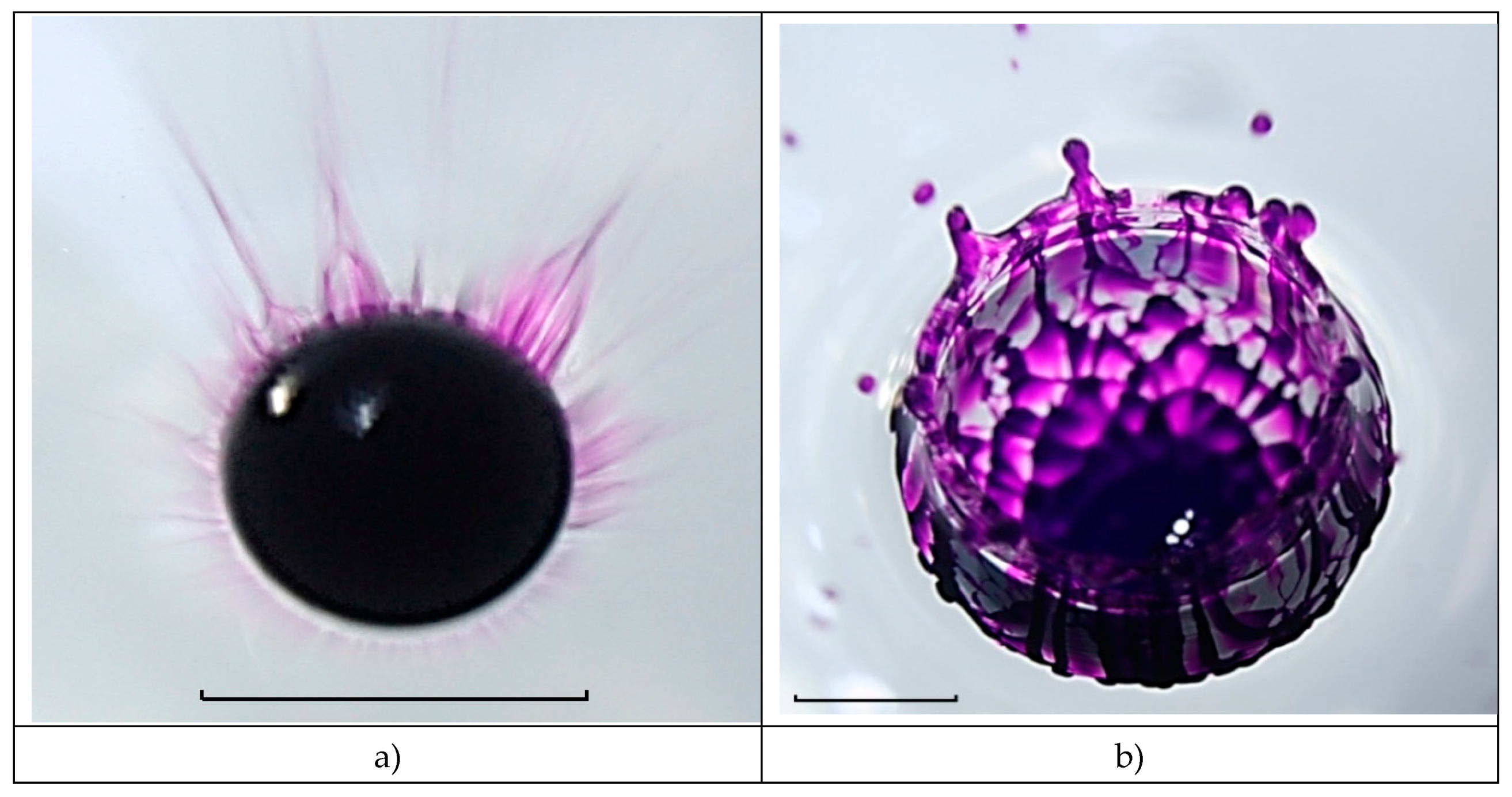
The flow photos at the beginning of the coalescence of a drop of potassium permanganate solution with water are shown in
Figure 10 a (the inclination of the sight line is
75° to the horizon). In the flow pattern, the "tongues" of the veil are expressed in the range of “10-11” and “13-14 o’clock” with a pronounced outer edge and an inner striped structure. The estimation of the velocity of the longest strokes (traces of droplets flying out from the spikes on the tops of the teeth), as the ratio of their length to the exposure time is
22 m/s (six times of the drop velocity
m/s). Careful consideration allows to distinguish thin strokes that have a continuation to the tops of the teeth, as well as those in contact with troughs at the boundary of the visible contact domain in the upper part of the drop.
In turn, the upper part of the boundary of the colored fluid is not a smooth line, protrusions and troughs with mm increments are distinguished in it. The transverse dimensions of the fibers on the veil teeth above the drop are mm or less. The question remains open about the coloring nature of the teeth, which may indicate the formation of a continuous inhomogeneously colored surface of the veil with thin trickles lying on its surface, or with separate isolated jets located in the space above and below the veil.
The outer wall of the developed spherical cavity, represented in the lower part of
Figure 10b, is covered with protruding fibers
mm thick, which are at a distance of
mm. Vortex heads of protruding jets appear on some fibers under the pigmented mesh nodes, which transform into vortex loops as the flow evolves [
48]. The original linear structure of the distribution of the drop matter is preserved on the wall of the falling crown remnant, covered with short capillary waves and in the upper part of the cavity. At the cavity bottom, fibers with a thickness from
mm form a three-tiered mesh with triangular and quadrangular cells of the size from
mm. Traces of cells are also visible in the central, more densely colored layer, under which the adjacent intermediate layer is located, which is shown in
Figure 8. Dark and light diffuse strips surrounding the cavity are shadow images of short circular capillary waves [
50,
51].
Either a single trickle flows to the tops of the teeth on the upper edge of the crown along its center, or a pair of trickles flow along the outer edge of the tooth, forming a spike, from the top of which sprays fly out.
4.3.2. Drop Spreading of Copper Sulphate Solution in Water
A distinctive feature of the flow during the primary contact of a drop of saturated aqueous solution of copper sulphate with water is also the abundance of rapid small sprays is presented in
Figure 11a (the inclination of the sight line is
75° to the horizon; registration: Canon EOS 350D with a 12mm macro ring, ISO 100, D 5.6).
The maximum length of thin strokes (traces of sprays) reaches
4 mm. Taking the stroke width as the diameter of the ejected droplet, and the length as its movement during exposure time,
0.25 ms, it is possible to estimate their velocity by the ratio
m/ s, which significantly exceeds the droplet velocity
3.8 m/ s. The existence of parallel strokes groups is the evidence of the successive ejection of droplets from the top of the same spike on the edge of the cavity veil, the position of which changes as the crown grows. In this experiment the sprays velocity
noticeably exceeds the drop velocity
–
The fact indicates the importance of the influence of the processes of converting APSE into other forms on the dynamics and structure of droplet flows [
16,
26,
40].
Droplet traces (strokes) are located on a pale background of a thin veil 1.25 mm wide, adjacent to a darker annular layer 0.9 mm wide, in contact with a light strip 0.14 mm (the image of the forming walls and cavity bottom). The density of the strokes indicates the high frequency of the process of the sprays generation on the spike tops at the veil or crown edge.
The drop spreads along the bottom as the cavity grows and in
Figure 11b it is possible to see the boundary of the contact domain of the merging fluids having a complex irregular shape. Basically, the veil and spikes are inclined outward, but in the lower part there are two sections of the veil, inclined inward.
The droplets from their tops fall on the surface of the merging drop and form short capillary waves (in
Figure 11b – in sectors for “6” and “8” o’clock [
52]). The complex structure of the fluids contact domain boundary (colored fibers visualizing thin trickles flowing along the cavity bottom, the crown walls and reaching the spikes on its edge) is preserved throughout the process of droplet coalescence (
Figure 11c, d).
Individual protrusions (precursors of the forming vortex loops [
48]) are also visible on the outer cavity wall in the lower part of
Figure 11b, c. In the enlarged images of the contact liquids domains shown in
Figure 12 fibers adjacent to the contact line and small-scale inhomogeneities of complex shape with a size of
0.22 mm are visible, forming a moving boundary of the coalescence domain. As in other experiments, the fibers containing the droplet matter go along the bottom, the walls of the cavity and reach the tops of the spikes on the veil edge [
45].
The colored fibers are traces of fast jets containing droplet matter (ligaments that violate the smoothness of the contact domain boundary of merging liquids). They flow for a long time while maintaining their angular position, leaving connected colored traces on the walls of the cavity and crown.
4.3.3. Spreading of an Iron Sulphate Solution Drop in Water
A large number of fast small droplets (sprays) are also formed when a drop of a saturated solution of iron sulphate FeSO
4 merges with water. However, the frequency of their ejection here is less than when a drop of copper sulphate solution merges with water. Splashes fly out from the tops of the spikes, to which thin trickles (ligaments) flow, penetrating the domain boundary where the droplet merges with water. Continuous trickles in
Figure 13a can be traced at the cavity bottom, the crown walls, above the crown edge.
However, the fine structure of the flow near the boundary of the fluid coalescence domain is more complex here than in
Figure 12. In the flow pattern, several groups of teeth are distinguished, the tops of which are wrapped inside the flow domain – two teeth in the left part, two teeth in the right part, three teeth at the bottom (angular position is at “3”, “6 and 9 o’clock”). Circular disturbances on the surface of the droplet residue in the lower part of the cavity bottom are systems of short capillary waves formed by the coalescence of sprays flying from the spikes on teeth tops [
52].
The coalescence boundary (the enlarged image of which is shown in
Figure 14) is uneven.
Fine fibers come out of periodic protrusions and troughs between them. The dark circular line on the cavity wall is the crest of a capillary wave running from the coalescence domain boundary.
Fibers (jets, ligaments, trickles) running from the uneven fluids contact domain boundary were observed in all experiments conducted with colored droplets in the impact coalescence mode. The high (in comparison with the falling drop velocity) speed of the liquid flow and the density of the additional kinetic energy of the flow in the ligaments were provided by the conversion processes of APSE, which was released during the fluids coalescence. The transformed energy was stored in the thin volume in which it was concentrated near the free surface.
4.3.3. Natural Shadowgraph Patterns of Water Droplet Spreading in Water
Changing the angles of inclination and the position of the water surface causes a redistribution of light flows and leads formation of the flow components distinctive images. Shadowgraph methods, which have been widely used in the study of fluid flows for almost two centuries [
53], can be also employed in the study of droplet flows. The resulting large gradients of the refractive index allows to trace the evolution of flow fine structure under the cavity water droplet in water by the direct shadowgraphy method [
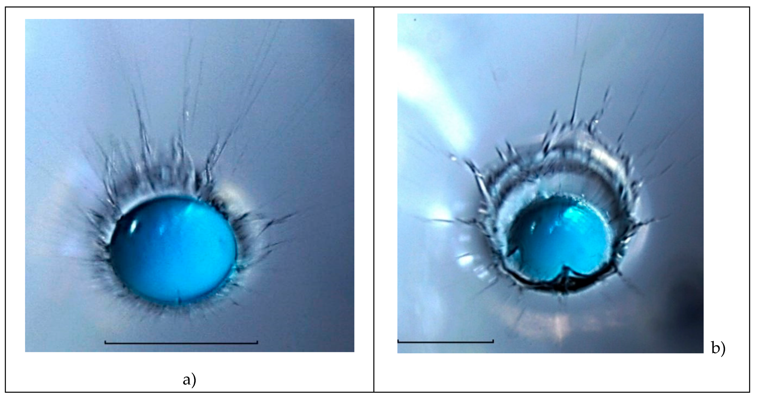
44]. The photos presented in
Figure 15, show the possibility of visualizing fibers (traces of trickles) on the surface of a complex-shaped liquid not only by tint, but also by observations of the redistribution of image illumination.
In the natural shadowgraph flow image shown in
Figure 15a , the merging drop residue in the center of the cavity is outlined with a dark line (the coalescence domain boundary). A light strip, which is wall and the growing cavity image, is penetrated by separate jets (ligaments). Thin jets that are generated in the domain where the droplet merges with the target fluid liquid deform the bottom. Part of jets penetrate the cavity walls, another part flow along a cavity bottom and is continued on the crown surface, then in the veil and finally form dark spikes protruding veil edge. They are especially distinguished in the upper right quarter of the flow. Sprays fly out from the spike tops, and are registered as thin strokes, the length of which reaches
4.25 mm. The maximum ratio of splash and drop velocities is
4.5. A large number of strokes above the crown and the veil is evidence of a multi–tiered level of sprays distribution flying out from the spikes on the edge of the veil or the crown [46].
The contrast of the flow components images is determined by the inclination of the surfaces, the location of the light source and photocamera [
46]. An uneven section of the boundary in the range of angles “10-12 o’clock” allows us to consider the visible boundary as the actual edge of the spreading drop. The boundary is radially stretched by thin-layer flows localized in the contact domain of the cavity shell and the near-surface layer of the target fluid [
16].
The resulting flows accelerate at the coalescence domain boundary, where the free surfaces are eliminated and the releasing APSE is transformed into other forms [
26]. In this case, together with the matter of the contacting media, a part of the extensive kinetic energy of the merging drop is captured by strays. It is the rapid release of the APSE that is the driver of the flow. At the same time, a noticeable contribution to the flow energy is created by the energy of the drop mechanical movement.
The spikes on the edge of the cavity can be a continuation of a single trickle (the upper left part of the flow), they can form during the coalescence of two edges of the veil (three spray lines in the upper right part of the figure). The question whether the observed structures are continuous jets or droplets collection consisting of a sequence of small components is still open.
As the drop merges, the number of spikes on the veil border decreases, their thickness increases, and the distribution of illumination in the upper part of the image takes on a diffuse character due to the reconfiguration of a large number of jet elements (
Figure 15b). Single jets can be seen more clearly in the lower part of the image. In the upper right corner of the angular position at “2 o'clock”, an inverted jet is visible, the top of which falls on the surface of the merging drop. Two clear contours appear in the flow pattern, one of which is the transition from the bottom to the cavity wall, and the second one is the boundary of the spreading drop at the cavity bottom. The images of the fibers in the lower part of the figure emphasize their origin at the contact domain boundary of the droplet residue with the target liquid.
Gradually, the spikes on the upper edge of the veil thicken, and the "strokes" (traces of more and more slowly flying droplets) shorten (
Figure 15c). At the same time, the inhomogeneous contrast of dark fibers on the walls of the crown and the cavity is preserved, which is determined by the shape of the surface and lighting conditions. The circular domain boundary where the droplet merges with the deformed liquid surface is visualized as well. In the lower part, the contact of the fibers with the contact line of the merging liquids at the cavity bottom is traced. The sequences of circular lines on the surface of the droplet residue, most pronounced in the sectors at “10” and “14 o’clock”, are images of a group of circular capillary waves running to the top of the flow from the expanding boundary of the contact merging fluids domain. A group of capillary waves in an angular position at "7 o'clock" on the surface of the drop residue is a trace of contact of the ejected spikes facing the flow center with the surface of the drop residue [
51,
52]. As the flow evolves, the inhomogeneities of the veil structure are smoothed out. The components of the structure on the crown edge and the cavity walls are enlarged.
The formation of additional structural components is accompanied by the emergence of new fine elements in the flow pattern, which, in particular, are expressed as light lines at the cavity bottom in the circular line vicinity of the drop residue coalescence in the “2-5 o'clock” sector. Their geometry, which correlates with the shape of the intermediate layer edge in
Figure 4 at
2.75 ms, confirms the formation of an intermediate layer under the cavity bottom in the impact mode of merging a water drop with water. The layer is created due to the mixing penetrating substance of the drop with the target fluid. At first glance, the identical physical properties of the contacting liquids in this experiment (tap water) exclude the formation of contrasting images of flow boundaries in the fluid thickness. However, the fact of their reproducible registration in independent experiments [
44] indicates the necessity for a more thorough study of the physical nature of the internal boundaries contrast formation. Perhaps the boundaries reflect large gradients in temperature distributions. Evaporative cooling lowers the surface temperature of a free-falling drop and creates a liquid layer with a changed refractive index, which persists during the flow evolution and is diluted by molecular diffusion processes, as well as the concentration gradient layer in
Figure 5 and 8.
A group of light ring strips in the sector of "7-9 o’clock" visualizes capillary waves running along the cavity wall. Radial strokes on the surface of the drop residue are traces of falling sprays. Vertical inhomogeneities of the structure of the cavity side wall in the "10-13 o'clock" sector are the traces of ligaments (thin jets flowing from the fluids coalescence domain boundary to the spikes on the edge of the crown or merged veil, the bases of which thicken over time, and the lengths decrease). Accordingly, the droplet sizes are growing, more and more slowly flying out from their tops.
