1. Introduction
An Autonomous Underwater Vehicle (AUV) is widely used in underwater exploration and scientific research. In AUV research, the control system of underwater thrusters can be said to be its neural center and the most complex technology, so the control of underwater thrusters is one of the most challenging problems in the field of control. Due to the crucial role played by AUVs in deep-sea environmental resource exploration. In recent decades, tracking control, the state maintenance, and path planning of AUVs have received attention from researchers, leading to an urgent need to develop new control theories in the theoretical and engineering fields of AUV output feedback control, making them fit for complex systems affected by various factors such as randomness, nonlinearity, and time delay. In addition, the control theory system built under the framework of certainly systems is no longer applicable to stochastic nonlinear systems [
1,
2,
3,
4,
5,
6,
7,
8,
9,
10,
11]. Therefore, it is a great challenge to solve the output feedback control problem of stochastic nonlinear systems by using stochastic control theory and related mathematical tools. In engineering practice, there is a high probability that the input and output of a controlled system are random signals. Therefore, the stochastic nonlinear system that combine the nonlinear and stochastic characteristics are a research area of considerable interest in the control theory community.
The application of trajectory tracking control is essential for autonomous underwater robots. However, due to the complex system, uncertain working environment, and highly coupled nonlinear characteristics of underwater robots [
1,
2], the controller design of AUV becomes very challenging. In the past decades, the design of trajectory tracking controller [
3] for underwater vehicles has been a problem worthy of attention. Traditional PID, LQR, and Kalman filtering [
4] can also control the trajectory of the underwater robot. In addition, nonlinear PID also has good performance in control. However, when the target trajectory being tracked is nonlinearity, the nonlinearity of the curved trajectory makes nonlinear PID no longer applicable in vehicle driving and class linear control techniques. Feedback linearization [
5] presents a powerful tool for dealing with nonlinear characteristics. However, applying feedback linearization to the AUV requires a system model with highly accurate hydraulic dynamic coefficients [
6]. In this context, the adaptive [
7,
8,
9] Lyapunov method has become the mainstream method for AUV trajectory control. In Article [
10], the dynamic controller is used for the first time in the backstepping control technique. AUV output backstep control can be found in Article [
11,
12]; another popular AUV trajectory tracking control method is sliding mode control. It is well known that this method has an excellent robust effect when the parameters are uncertain, but the sliding effect of sliding mode control tends to appear discrete. In order to reduce this phenomenon, sliding mode control is often used in combination with control methods such as robust control, adaptive control, and PID [
13,
14,
15].
Nonetheless, the above control methods have a general deficiency the inability to deal with the stochastic characteristics and uncertain disturbances of the system. For AUVs, stochastic and uncertain are very common [
16,
17], which the actuator must suffer in the working environment or the system’s characteristics. Adaptive control is featured in dealing with this randomness and uncertainties [
18], which proposes a robust control structure in the face of this wide range of control problems. In addition, adaptive control can solve complex nonlinear problems for solving the control problems of AUV dynamic systems. So far, we do not have a very effective control method for trajectory tracking control problems. In article [
19], a self-correcting adaptive method is proposed, a complete method to solve the problem that its dynamic parameters and even the model structure often change. The trajectory tracking control algorithm for AUV stochastic uncertain nonlinear system is proposed. In paper [
20], where the concept of stochastic and uncertain is creatively introduced. In article [
21,
22], a comprehensive trajectory tracking control and path planning problem is researched. A unified optimization framework [
23] is developed for the problem of AUVs combined motion control.
Although an adaptive control based on an integral high-order sliding mode concept provides a good algorithm for nonlinear systems with random and uncertain disturbances [
13], when solving, this method heavily burdens the computational bottleneck. In theoretical research, the computational time is often ignored, but in practice, the computational difficulty increases exponentially with the increase of stochastic and uncertain interference problems. Due to the short sampling period, many strategies such as iterative methods, precomputation, and numerical continuation [
24] have been proposed to decrease the computational complexity and reduce the computational time. By exploring the motion characteristics of underwater robots, a dynamic-static combined with a high-gain observer is successfully applied to the output feedback adaptive control algorithm. However, the stability proof of the closed-loop system in paper [
25] is not provided. Since the dynamic gain control, algorithm solves the trajectory tracking control problem of the underwater robots. The implicit coupling of the system state and the control signal complicates the stability analysis of the closed-loop system. It is urgent to find a better stability analysis method.
This paper hope to provide a method to eliminate the influence of random and uncertain disturbances on AUV trajectory tracking and simultaneously ensure the closed-loop system stability. Here, the reference augmentation technique is applied to modeling the AUV system so that the coupled motion between the systems is weakened [
26]. Then the dynamic gain method is studied to reduce the computational stress of stochastic uncertain nonlinear systems. Since the novel dynamic gain, adaptive control algorithm was proposed, the complex control problem has been changed into a parameter selection and construction problem through dynamic gain. The computational complexity is significantly reduced and the computation time is significantly reduced. The contributions of this article are as follows:
1. Aiming at the problem of AUV trajectory tracking control, a well-known stochastic uncertain nonlinear dynamic adaptive control algorithm is provided to study the AUV motion’s dynamic characteristics.
2. A novel dynamic-static combination of high-gain observers is proposed, which dramatically reduces the computational complexity of the control algorithm and transforms the controller design problem into a parameter calculation and selection problem.
3. Investigate fundamental properties of closed-loop systems. The control time and control error of AUV trajectory tracking is remarkably reduced, the control effect is incredibly optimized, and the sensitivity is improved.
4. Numerical simulations and additional experiments reveal that the proposed dynamic-static high-gain adaptive control algorithm has excellent robust performance against stochastic and uncertain disturbances.
The rest of this paper is organized as follows: The second section describes the AUV motion model. The third section is the dynamic and static high-gain adaptive control algorithm.
Section 4 presents simulation studies and additional experiments. The fifth section is the conclusion and prospects.
2. Description of Dynamic Modelling of Robot
In this section, the dynamics analysis of the AUV is carried out. According to the analysis of the power, resistance, and inertial force when moving underwater, we can obtain the general dynamic equation. Considering the complexity and uncertainty of the underwater environment [
2,
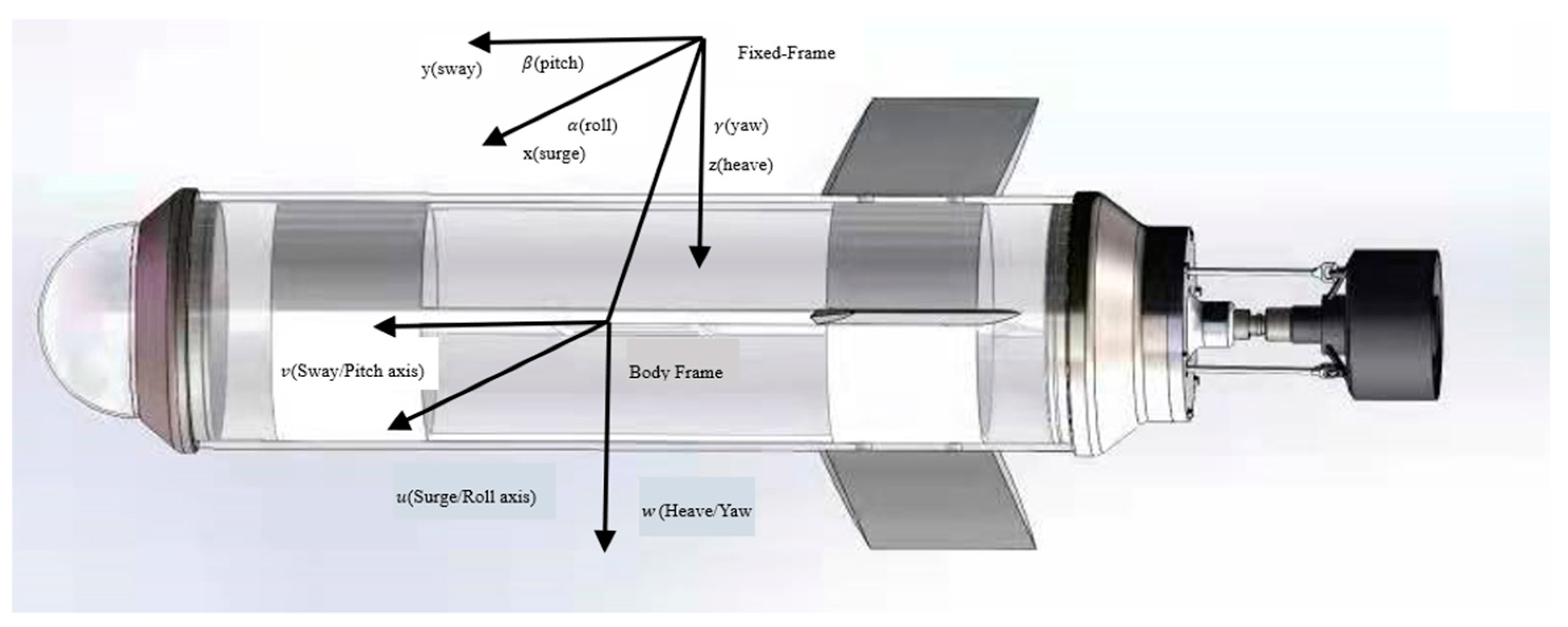
27], a stochastic process was added to the model. Based on the established underactuated underwater robot model, as shown in
Figure 1.
The 6-DOF dynamic model of the AUV can be expressed as follows:
where is the inertia mass matrix, which contains AUV additional quality. are Coriolis force matrix of the underwater vehicles. is for underwater vehicle fluid damping matrix. stands for the gravity of the underwater vehicle in operation and the restoring force (moment) matrix generated by the buoyancy. stands for the resultant forces and moments. are the linear and angular accelerations of the body (moving) frame in the direction of pitch, roll and heave, stands for the linear and angular velocity with respect to body (moving) frame, – surge velocity, – sway velocity, – heave velocity, – roll rate, – pitch rate, – yaw rate. are the position and orientation in inertial(fixed) frame, – surge position, – sway position, – heave position, – roll angle, – pitch angle, – yaw angle.
According to the above, the six-degree-of-freedom (6-DOF) model of the underwater robot has complex nonlinearity and state coupling. If the paper wants to design a controller with six degrees of freedom, it will pose a great challenge to the controller design and physical characteristics. Here, we decompose the 6-DOF motion model into two kinematic models, which is linear velocity variables and angular velocity variables . In the earth-fixed frame, the velocity can generally be decomposed into two kinematic models, underwater robot position and underwater robot orientation , which can highly simplify the AUV model. In this paper, we only consider the velocity variables and linear motion of the AUV underwater.
The relationship between the fixed frame and body frame in linear velocity is as follows:
is the kinematic transformation matrix of the following form:
Where,
,
and
is the angle between the surge, sway and heave direction and the earth frame, respectively. When
, this transformation is undefined and the quaternion method has to be considered. While, most robots are designed to operate at pitch angles below
; Thus, this restriction is of no great significance here. In order to better understand and analyze the motion state, we will study the AUV system based on the earth reference frame. In order to unify the signal states, using Eq. (2) for coordinate transformation
, we obtain:
The coordinate transformation is a global diffeomorphism analogous to a similarity transformation in the linear system. The dynamic underwater vehicle model with the earth fixed reference frame is as follows:
We need some assumptions as follows.
Assumption 1. In this paper, only the velocity between the self-position and the fixed frame is considered, the velocity is . Suppose the origin state and .
Assumption 2. In this paper, the velocity and the angle are known using the sensors.
In this paper, we focus on the problem of trajectory tracking control for a class of stochastic uncertain nonlinear systems. For the trajectory tracking control problem of the underwater robot under nonlinear dynamics, to better design the control algorithm, we convert the dynamic model of the system into a broad numerical model as follows.
In the stochastic nonlinear systems , , are the states, input and output of system, respectively; is the target trajectory to be tracked. Where state and are unmeasurable. The stochastic process of the system is introduced in this paper: is an m – dimensional standard Wiener process defined on the complete probability space , where is the sample space, is the filter, and is the probability measure. Nonlinear term is satisfied continuous polynomial growth conditions and local Lipschitz.
In this paper, we assume that system (5) satisfies the following assumptions and implements output feedback tracking control.
Assumption 3. There exists a positive constant
and a known integer
such that the following inequality holds
This assumption shows that the output polynomial growth rate governed this system (5).
Assumption 4. The target trajectory , is known constants. According to the description of the above system, this section’s goal is to design a time-varying gain constructive control algorithm: for any given in advance tolerance . In the closed-loop system, all the states are well-defined and globally bounded on in finite time , for instance .
Remark 1. It should be pointed out that the output feedback tracking control problems studied in previous literatures [
28,
29] are mainly aimed at nonlinear systems or nonlinear systems with parameter uncertainty and unknown control direction. The system (5) studied in this paper is a stochastic uncertain nonlinear system after introducing random factors. At the same time, system (5) is observable by Assumption 3, which depends on the unmeasurable state and nonlinear growth conditions satisfying the polynomial growth condition, according to Assumption 4. It can be seen that for the reference trajectory
, its upper bound value and the upper bound value of the derivative are given, which means that it is not necessary to give a specific description function or give more information to the reference trajectory
.
Based on this assumption 3, 4 and (5), for the
. We have:
where
is a known constant.
3. Dynamic and Static High Gain Adaptive Control Algorithm
In this section, we propose a dynamic gain observer strategy to achieve dynamic adaptive tracking control, so that the complexity can be greatly reduced, which will study the stochastic uncertain nonlinear underwater robot system in two steps. The first step is the dynamic gain observer and controller design of the AUV system; the second step is stability analysis and implementation of the AUV system.
3.1. Dynamic Gain Observer and Controller Design
First step, this section is to introduce the following state transformation:
So, we can get the system (9).
where
Since the states of the stochastic system are unmeasurable except for
, which is a measurable state, the time-varying observers are first constructed:
Meantime, we choose design parameters
, are constants and satisfying Hurwitz condition and
. The
is a dynamic gain parameter, which
is a constant and
is a time-varying function updated by
Theorem 1. So far, we can conclude that all closed-loop system states are bounded on
, then
must be infinite. Otherwise, at least one state will escape at
, contradicts the continuity of the closed-loop system. For a class stochastic uncertain nonlinear system (5),
is the output, and the nonlinear term of the system meets Assumptions 3 and 4. According to choose the suitable parameters
and
and based on observer (11), the output feedback controller is designed as follows:
where the parameter
is a constant vector and satisfying Hurwitz condition and
. Next, we will to prove that practical global tracking can be achieved when
is large enough. Furthermore, practical path tracking can be achieved. For any
, there exists a finite time
, such that
.
Remark 2. Through equation (8), we can turn complex systems into simple ones. According to the unmeasurable state of the system, we introduce a dynamic gain observer (11) to construct the observation time of the system state. Unlike the previous observers, the observer gain in this paper is an observer combined with dynamic and static gain parameters. The observed effect is closer to the actual value of the system, which provides a good condition for the following controller to control the error variable. On account of the insufficient information on the system and the tracking signal and the system’s instability after introducing random factors, the common tracking control methods, such as the MPC method, can no longer solve the problems in this chapter. For these challenging problems, this article will pay close attention to stochastic nonlinear systems satisfying assumptions 3 and 4 by constructing an output feedback dynamic adaptive tracking controller ground on the combination of the static and dynamic gain observer to achieve the original system (5) the actual tracking control target.
3.2. Stability Analysis and Implementation
In this subsection, the main results of the paper are presented and harshly proved. For the stability analysis, we need the following scaling transformation for the closed-loop system.
The state estimation error is defined as
. Then the dynamics of
satisfy:
To facilitate the design of the controller, we need to transform the estimated state
and the error state
as follows:
where
is a known constant,
. According to (15), stochastic nonlinear systems (9) and (11) can be converted as follows:
Meantime, .
Then, we discuss the gain
and the boundedness of the states
and
. Above all, choose the proper parameters
, so that the relationship between the positive definite matrices
and the matrix
satisfies:
Let
be the Lyapunov function candidate. Then along the trajectories of (16), the time derivative of
on
satisfies the following inequality:
From Remark 2, we can know
, and from (12),
.
Then, from this and (17), we have
By Assumption 4, (7), (8), (15) and the fact
we have
Split and enlarge the terms in formula (18), and we can get
Therefore, combining equations (18)-(22), the system Ito differential equation can be obtained as:
Where the last term of formula (23) can be enlarged as:
After finishing, we obtain
According to formula (25), selection satisfies:
According to
, choose
to satisfy:
According to the above selection of parameters, the formula (25) can be transformed into:
The relevant parameters are defined as follows:
As previously mentioned, the closed-loop system has a unique solution on the maximal time interval
, where
.
which shows that
are bounded on
.
Then prove the boundedness of
on
because
in
on the bounded, and
, we get
. Then from this, (12) and
, it is easily to get that
And hence is ounded on .
Proof 1 It is easy to verify that the resulting closed-loop system is locally Lipschitz in the open neighborhood of the initial conditions of
. Therefore, the closed-loop system has a unique solution on a small interval
. Let
be the largest interval for which a unique solution exists, where
. As stated in Lemma 1, where
, the closed-loop system states are defined on
.
It is important to point out here that
contains parameter
. From this, it is evident that
Combining (34), (36) and
, we can get:
Then, we know that for all ,
Combining (37) and in turn
From this and , when , by choosing big enough to make any small , so as to realize the actual path tracking.
Remark 3. By analyzing the dynamic gain parameter of the dynamic observer, we can see that this method turns the control problem into a parameter selection problem through analysis, which can be found that as long as the more prominent the parameter selection area is, the better the control effect will be. A dynamic high-gain state observer is constructed. With the help of Ito stochastic calculus theory, the output feedback actual tracking controller is obtained. By selecting appropriate design parameters, the state and high gain parameters of the closed-loop stochastic nonlinear system are guaranteed to be bounded, and the system tracking error can be converge to zero within a small neighborhood. The study of output feedback tracking control for nonlinear systems is extended to stochastic systems. The practical tracking of output feedback for a class of stochastic nonlinear systems satisfying the growth condition of the output polynomial function is studied for the first time.
