1. Introduction
Natural Fractured Reservoirs (NFRs) are among the most common hydrocarbon reservoirs globally, containing more than 50% of the known oil and gas reserves [Saidi 1987]. NFRs are distinguished by interconnected fracture network of high permeability and low storage capacity that serves as the primary flow path. In contrast, the rock matrix serves as the hydrocarbon source [Van Golf-Rach, 1982]. These reservoirs are well known for having poorer recoveries than their counterpart clastic reservoirs due to production characteristics and geological heterogeneities [Allan & Sun, 2003; Kharrat et al., 2012; Agada et al., 2016; Aljuboori et al., 2019; Luo & Mohanty, 2021]. Furthermore, channeling and fingering of the injected fluid may be a result owing to the complexity of the natural fracture networks [Xu et al., 2020]. Increasingly, NFRs recoveries ensure a steady supply of resources to international oil markets. Consequently, redevelopment of currently producing fractured reservoirs requires maintaining the supply but adequate fracture characterization and modeling [Kharrat et al., 2021; Kharrat & Ott, 2023]. Therefore proper fracture identification and characterization are essential for understanding fluid displacements, especially for improved and enhanced oil recovery [Guerriero et al., 2013; Pejic et al., 2022]. Recent studies have focused on modeling and simulating fluid flow in fractured subsurface systems due to the potential hydrocarbon reserves in fractured reservoirs [Gong & Rossen 2017; Gong & Rossen 2018; Kharrat et al. 2021; Gugl et al. 2022; Pejic et al. 2022].
Among the enhanced oil recovery (EOR) methods, gas injection (GI) has a wide range of applications in NFRs for various reasons, especially the availability and good injectivity of gas compared to water-based EOR Methods. Based on reservoir conditions, the immiscible or miscible gas injection might result in a successful EOR process [Mogensen & Masalmeh, 2020]. However, gas injection might benefit these types of reservoirs if operated in the gas-assisted gravity drainage (GAGD) mode [Aljuboori et al., 2019; Kharrat et al., 2021]. According to Silva and Maini, 2016, the storage and transmissibility capacities, as well as the direction and intensity of the fracture, are the key features of the GAGD process. Since the reservoir's production potential is determined by the storage and transmissibility capacity, fracture intensity and direction describe the flow pattern in the reservoir. Hence, information and implementation of fracture intensity and direction are important in assessing the GAGD recovery mode. Fracture intensity is thereby a controlling parameter for EOR and gas storage in a fractured reservoir, i.e., for carbon dioxide sequestration. A high fracture density forms massive continuous flow paths and makes the specific geometry of the fracture insignificant [Agada et al. 2016].
The gravity override and unfavorable mobility are the main cause of the poor sweep efficiency during gas injection. Consequently, it is necessary to utilize certain chemicals like surfactants or techniques such as gas-based EOR processes, which involve alternating water and gas injection in cycles. Foam can potentially serve as an alternative method for decreasing gas mobility and redirecting gas flow away from fractures and toward the reservoir matrix. Nevertheless, the precise mechanisms of foam injection and its interaction with different fracture types remain inadequately explored, especially in fractured carbonate reservoirs characterized by high salinity, divalent ions, and elevated temperatures [Mogensen & Masalmeh, 2020; Xu et al., 2020]. Therefore, Gas-based methods such as WAG and FAWAG methods are introduced to overcome the deficiencies of gas injection [Heeremans et al., 2006; Ayoub et al., 2014; Gbadamosi et al., 2018; Gugl et al., 2022]. However, the modeling and simulation of WAG and FAWAG include additional complexities, such as three-phase flow, especially for carbonate reservoirs. It has its challenges due to the flow functions that define the physics of fluid displacement in the fracture and the matrix, particularly the three phases transfer function [Elfeel et al. 2016].
Simplifying the model by excluding, including, or homogenizing fractures is a common practice in the simulation of fractured reservoirs. However, the heterogeneous distribution of fracture characteristics can considerably impact fluid flow behavior, leading to variations in recovery performance [Alfeel et al., 2019]. Additionally, the behavior of produced fluids over the injection period can also be affected [Alalim N., 2022], making fracture characteristics essential in the history-matching process of such reservoirs. Notably, a case study of a giant carbonated reservoir with a production history spanning over ninety years demonstrated improved prediction accuracy when all fracture networks were included, except for hairline fractures, which had a minor effect [Pejic et al., 2022]. Similarly, Aljuboori et al. (2020) confirmed the significance of fracture characteristics in history matching for a carbonate reservoir with a 40-year production history, emphasizing the importance of accurate fracture identification and modeling.
Water flooding processes have also been shown to be influenced by the types of fractures, with a remarkable observation that a relatively small number of fractures accounted for a major portion of the injected water flow [Gong and Rossen, 2018]. A recent study involving a 2D model with major, medium, and minor fracture networks observed that oil was displaced primarily in the fractures during the early production period, while drainage from the matrix occurred later. During this initial production period, the fracture network's impact on recovery was more pronounced, while the minor fractures had a comparatively smaller effect [Pejic et al., 2022].
Therefore, precise evaluation of both the matrix and fractures is crucial for a comprehensive approach, and accurate identification and modeling of fractures may significantly enhance the history-matching process and overall understanding of gas-based enhanced oil recovery methods in fractured reservoirs. Limited studies have been reported on the impact of fracture effect on the gas-based EOR processes; hence more work is needed. Generally, the dual continuum approach is used for modeling and simulation, where fracture properties are subjected to upscaling and homogenization [Bourbiaux B., 2010; Kasiri N., 2011; Lei et al., 2017; Bosma et al., 2017]. In certain cases, it may be necessary to reassess the fracture characteristic inputs based on the recovery process that has been implemented. The possibility of modeling different discrete fracture networks has been recently introduced without further upscaling processes [CMG 2020]. This approach can thoroughly facilitate the study of different fracture types and their impact on production. This work aims to investigate the impact of fracture network sets on the recovery of gas-based processes using the recent CMG DFN modeling approach.
2. Methodology
A two-dimensional vertical slice model is constructed to study the impact of fracture type on recovery for gas-based EOR methods. Vertical and horizontal injection schemes were used to investigate whether fracture networks are sensitive to the respective propagation direction. Moreover, an extended vertical model with two slices is used to investigate the assisted drainage mode. The model dimensions, grid size, and related properties are shown in
Table 1. A single porosity domain was used to represent the reservoir rock with an isotropic matrix permeability of 1mD with a matrix porosity of 20%. Three sets of fracture networks were defined in each model: major, medium, and minor sets of fractures with maximum and minimum apertures of 2 and 0.20 mm, respectively. In
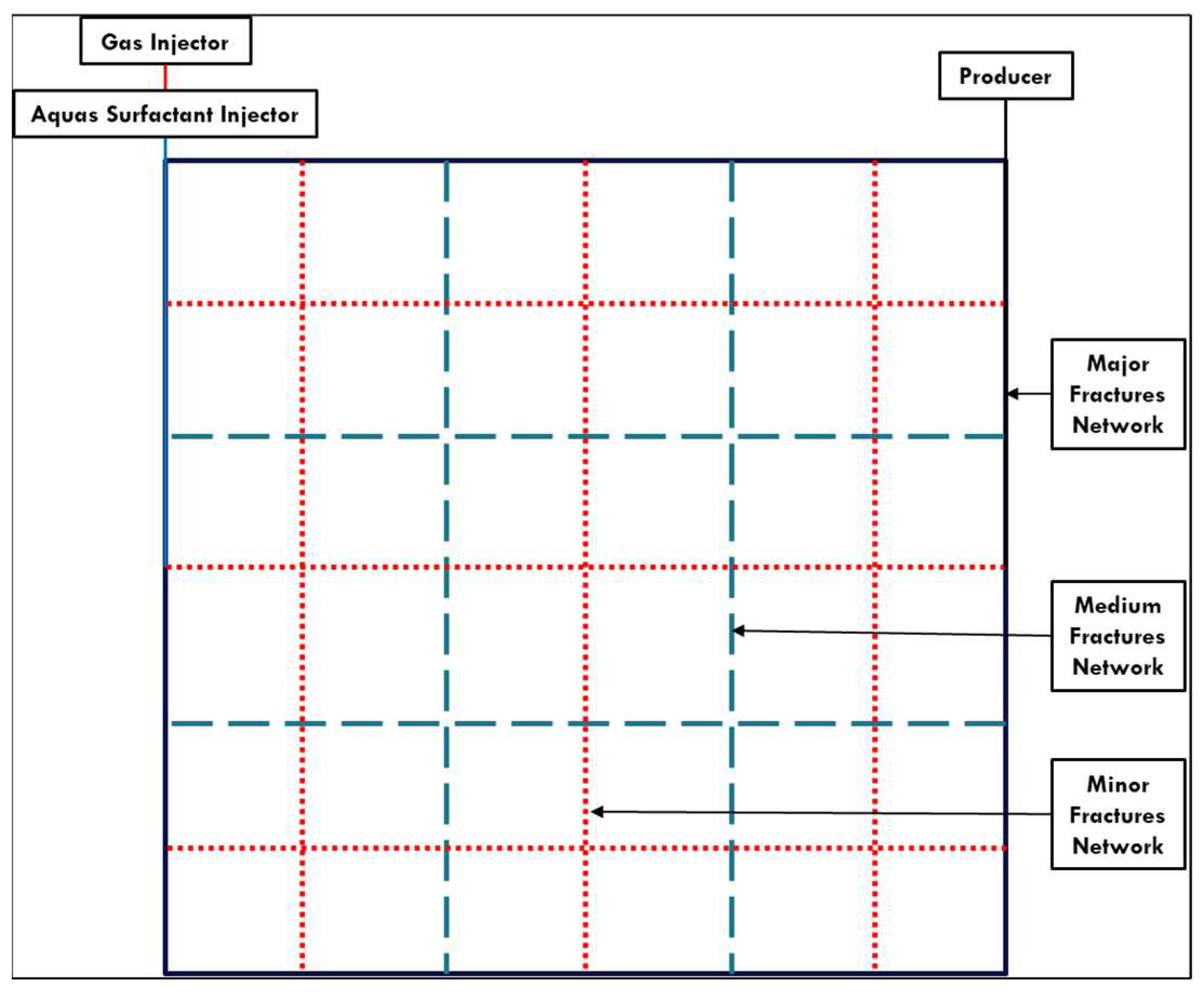
Figure 1, the exact locations of the fractures and the wells can be observed. A heterogeneous distribution is assumed for fracture aperture, i.e., fracture permeability.
With the CMG 2020.1 update, it is possible to model various discrete fracture networks without requiring additional upscaling procedures. The discrete fracture segment (DFS) and discrete fracture unit (DFU) are introduced for DFN. The control volume segments are embedded by defining the explicit location of the DFN. Each fracture plane intersects directly with the corresponding matrix grid to form a connected network. The DFN is discretized based on the shape, orientation, aperture, and permeability of a DFU. Then based on the intersection with the matrix grid, each DFU is discretized into a DFS. The flow ability of the fracture is then determined based on the fracture aperture and permeability [CMG, 2020]. In this approach, the flow description within fractures does not require data on capillary pressure and relative permeability but is connected to the matrix. Thus, this study utilized this approach to examine the effect of different fracture network sets on the production and recovery processes.
Dimensionless numbers, namely R
m12 (major-to-medium aperture ratio), R
m13 (major-to-minor aperture ratio), and R
n (number of major fractures-to-total number of major and medium fractures), are introduced to characterize system heterogeneity based on fracture apertures, as defined in equations 1, 2, and 3, respectively [Gong & Rossen, 2017]. Additionally, these dimensionless numbers allow us to descriptively describe the fracture properties and their influence on the recovery factor for each recovery process.
For each case, the fracture permeability was varied by variation of the fracture aperture using the cubic law. Three categories were defined to cover a wider range of properties for each set of fracture networks, from coarse to fine. The properties for the different categories and the resulting dimensionless number are summarized in
Table 2. As can be seen, the major fractures' aperture and permeability are constant in all categories. Fracture permeability was selected as higher than the matrix for all the cases to avoid any numerical issues, as Wong et al. (2020) recommended with a similar Embedded District Fracture Model (EDFM).
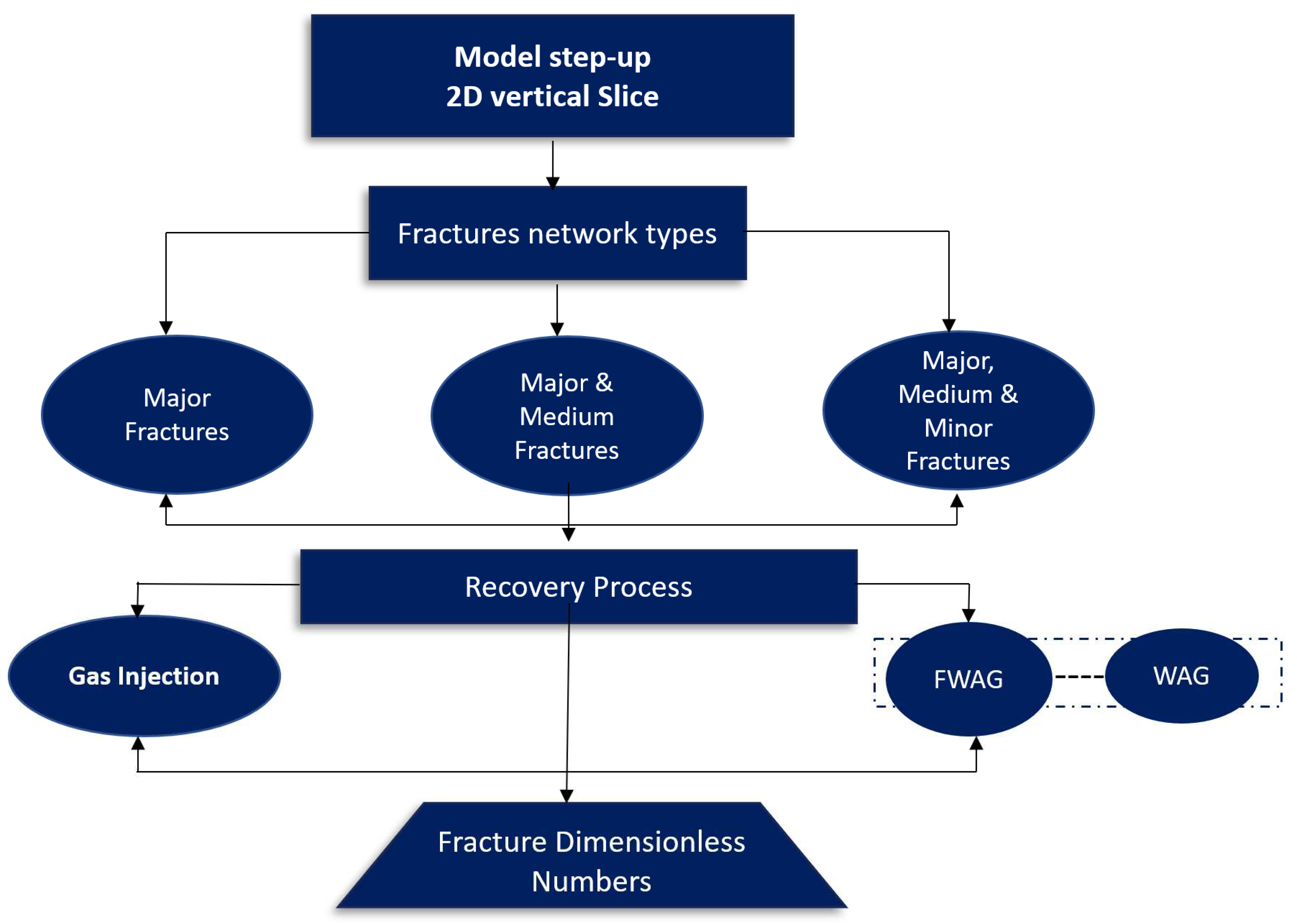
Different combinations of fracture types were implemented in the constructed 2-D model. The fracture set effect was in terms of major only, major-medium, and major-medium-minor with 1, 9, and 36 blocks, respectively. For the CGI, horizontal and vertical displacement modes were considered, while only horizontal displacement was used for the FAWAG and WAG. In the WAG and FAWAG processes, the water was injected at a half height of the matrix block to avoid gravity segregation and promote the interaction between the phases. Thus water flows in the lower part and the gas in the upper part model. The workflow of the study is illustrated in
Figure 2. Based on these models, several cases with different objectives were defined to investigate the properties change for these non-major fracture networks and compare it to the case when these networks are excluded. In all the cases, two pore volume was injected.
At first, the immiscible gas injection was investigated using IMEX-CMG black oil model. Then the FAWAG and WAG processes with a ratio of one to two cycles were studied using GEM-CMG compositional model. For Foam, the GMSMO85 CMG model was adjusted to simplify the modeling process and maintain this study's main target in investigating the fracture networks' effect on the recovery process. The fluid properties of the gas injection process and Foam are summarized in In this research, we employed the implicit-texture local-equilibrium approach to investigate the foam injection process, following the methodology established by Ma et al. in 2015. The foam quality, representing the ratio of the gas rate to the total fluid rate, was defined based on the work of Luo & Mohanty (2021). For this study, we utilized the foam empirical parameters and relevant equations previously documented by Alalim in 2022.
3. This approach involves the generation of Foam in the presence of a surfactant component in an aqueous and a gas phase. It assumes the presence of Foam wherever surfactant is present. The Foam properties are characterized by several empirically determined parameters, like the foam mobility reduction factor [CMG 2020].
In this research, we employed the implicit-texture local-equilibrium approach to investigate the foam injection process, following the methodology established by Ma et al. in 2015. The foam quality, representing the ratio of the gas rate to the total fluid rate, was defined based on the work of Luo & Mohanty (2021). For this study, we utilized the foam empirical parameters and relevant equations previously documented by Alalim in 2022.
3. Results and Discussion
The impact of fracture types on GI, WAG, and FAWAG processes is analyzed and discussed using the dimensionless numbers defined earlier. Various simulation scenarios are explored, with some cases involving only a primary (major) fracture network as the basis of the simulation, while others include an additional major fracture. Additionally, certain simulations incorporate connected medium and minor fracture networks. Moreover, both horizontal and vertical displacement modes are taken into account.
3.1. Gas injection
3.1.1. Horizontal Displacement Mode
At first, verticle wells in a single block (one slice) were used to investigate the gas injection mechanism, where the displacement is from left to right. The gas injection results for the three categories are discussed in this section.
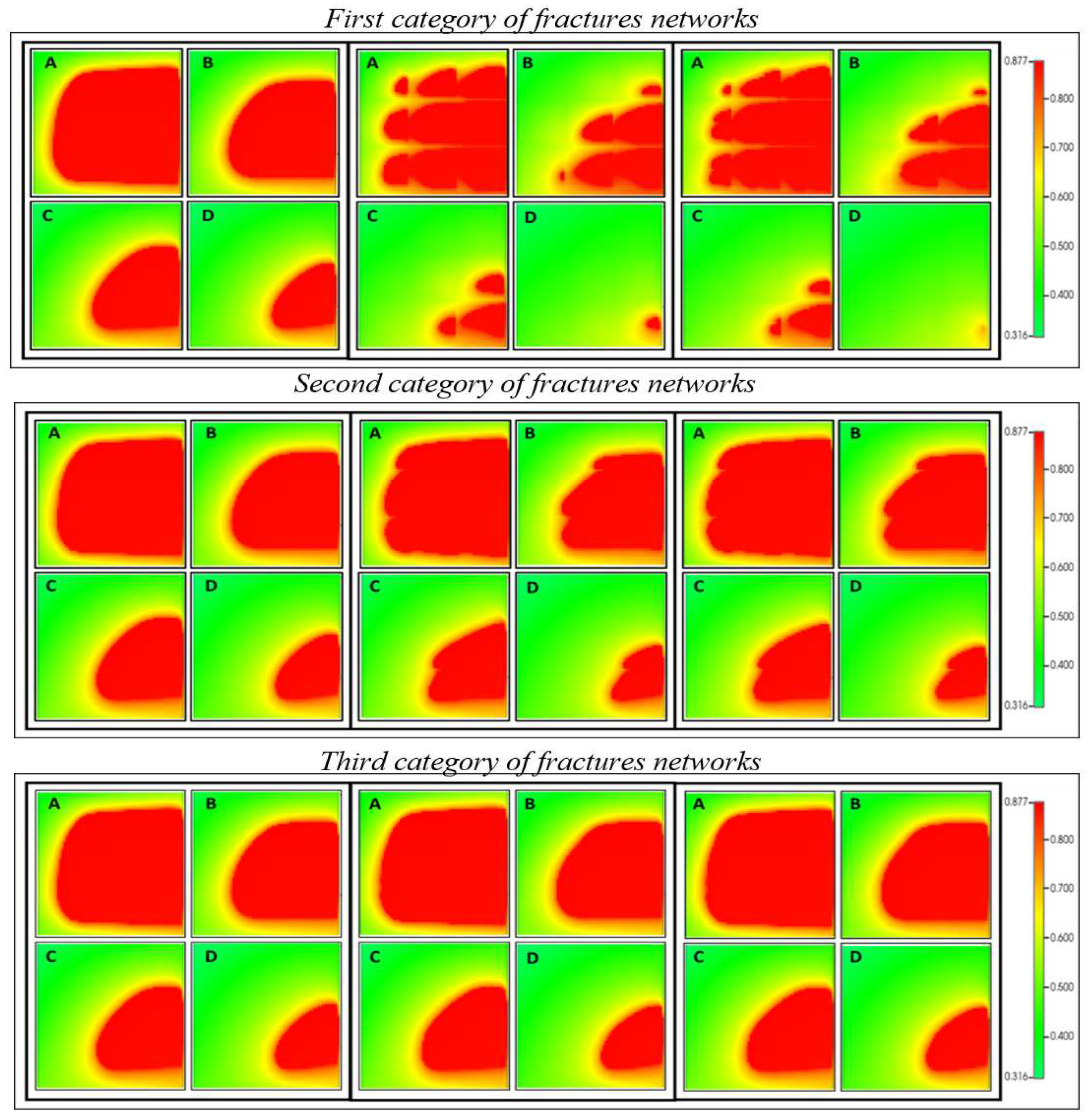
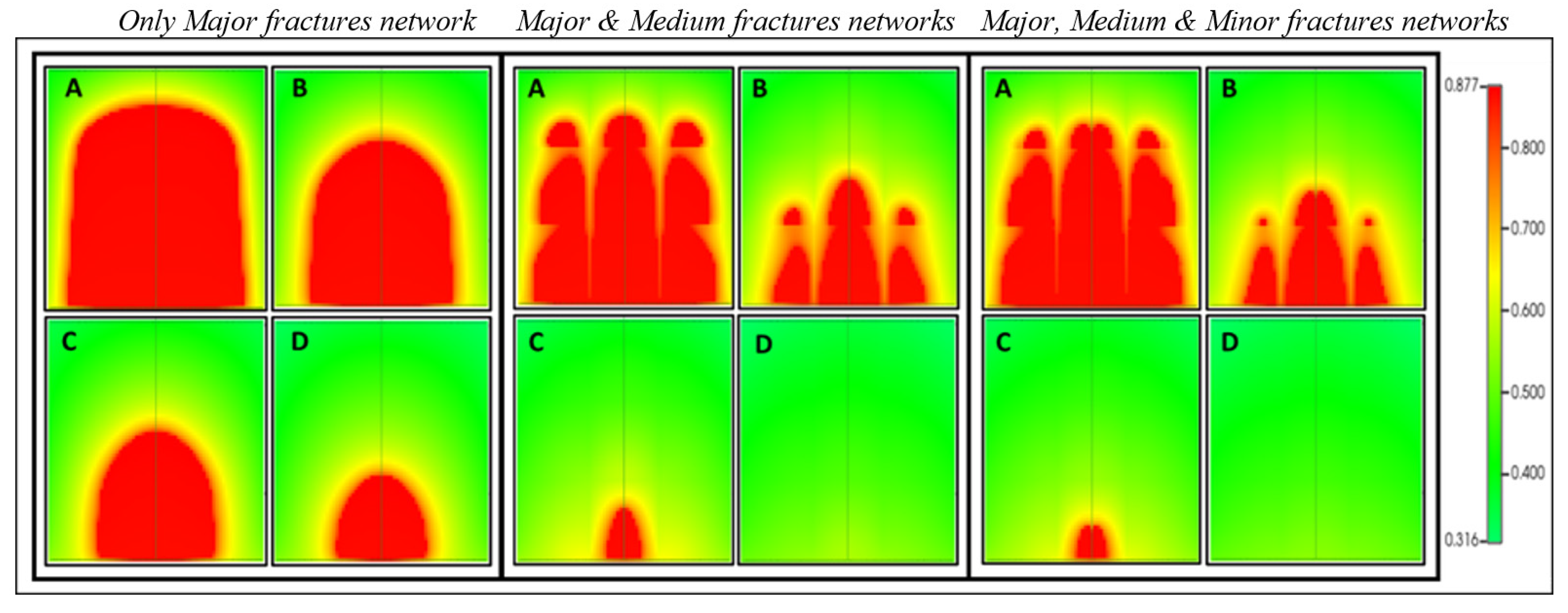
Figure 3 shows the resulting oil saturation profile at 0.5, 1, 1.5, and 2 pore volume (PV) for the three fracture-network categories defined above; only major fracture, major and medium fracture, and all fractures included. Based on the observed results, the gas flows first in the primary fractures network, surroundings the matrix block, and gradually drains the matrix. The gas flow parallels the flow direction in the horizontal fractures by including the medium and minor fractures. In contrast, the gas flow in the vertical fractures was subjected to re-infiltration of the oil from one matrix block to another and gravity effect. The oil gradually drains as the gas saturation increases and surrounds the matrix block. By including all fracture networks, slight differences can be observed even in the first category, explaining the small effect of the Minor fractures network. This is in agreement with the observed results published for a single porosity model and matrix block, especially for the second and third-category networks where smaller blocks are used, and the aperture size of the non-major fractures is small [Elfeel et al. 2016; Aljuboori et al.,2019].
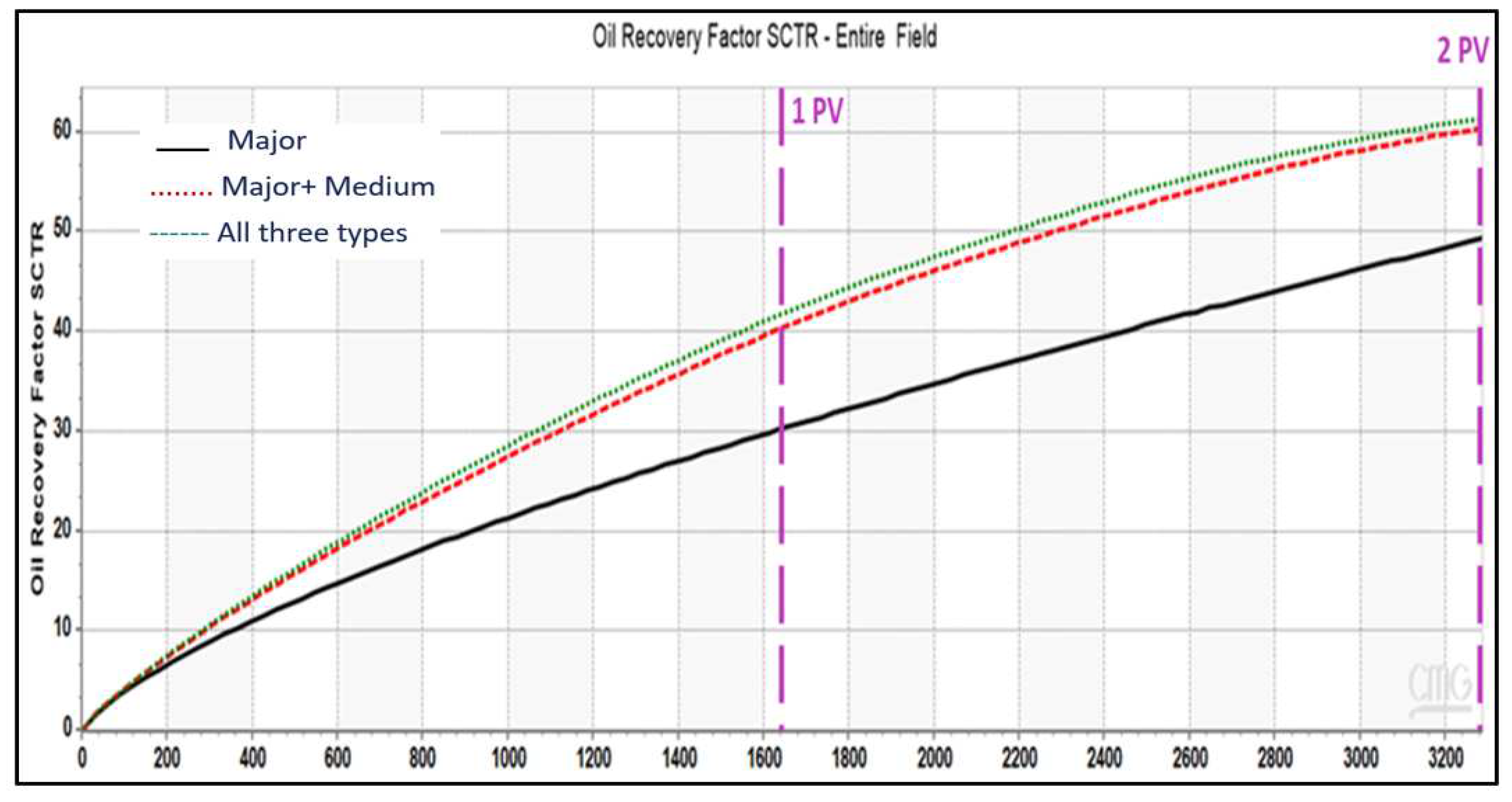
The comparison for the recovery factor of the first category indicates that the difference after the complete injection of 1 PV can reach 11% in the first category and results in an underestimation of the recovery factor when the medium and minor fracture network is excluded (
Figure 4). In the second category, the difference magnitude decreases to reach 3%. In the third category, almost no difference can be indicated. This indicates that their impact on recovery decreases as the aperture size of the non-major fracture networks decreases.
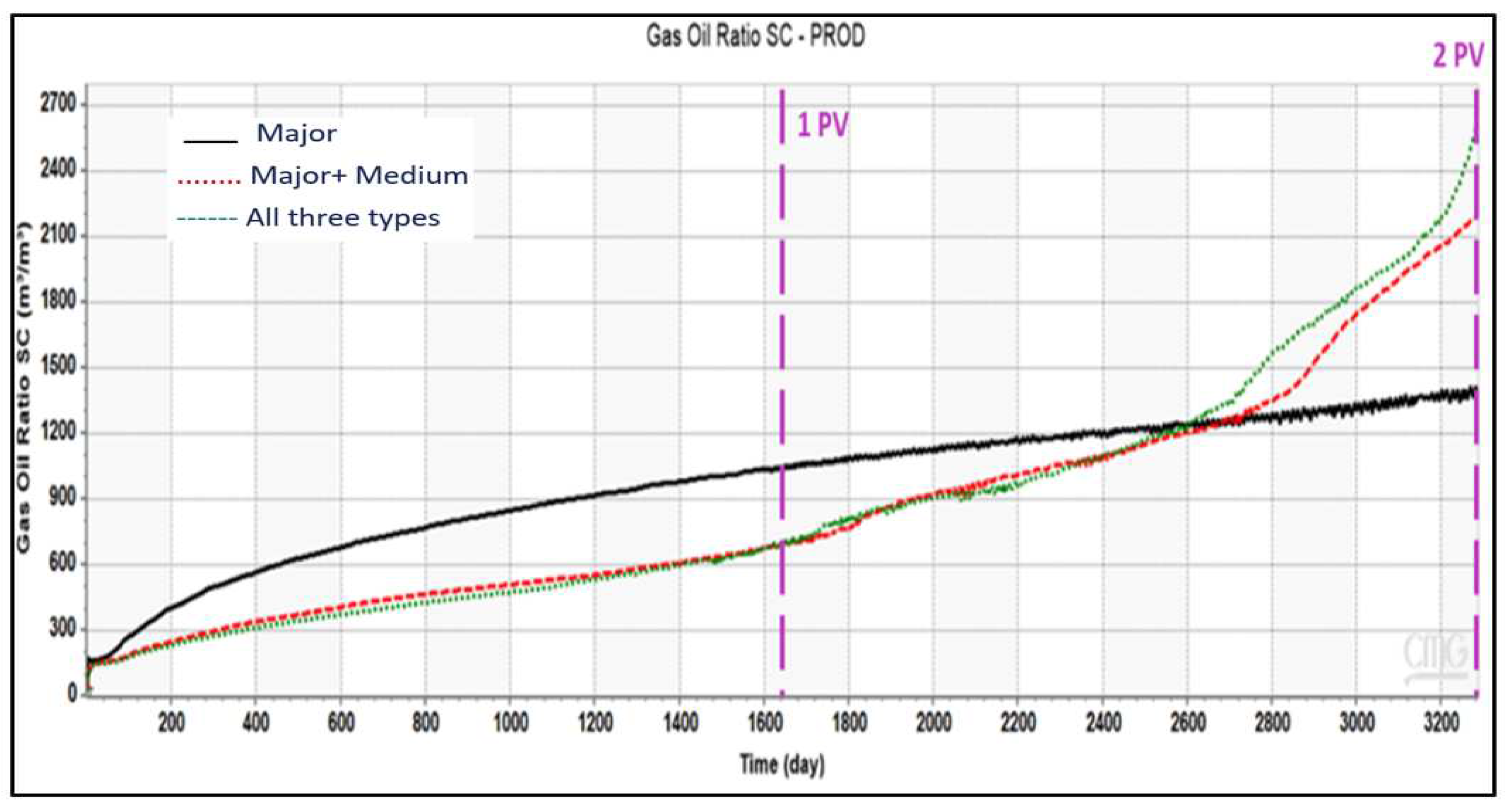
Figure 5 displays the gas-oil ratio of the gas injection process for the first category. The simulated GOR indicates an entirely different behavior with the inclusion of the medium and minor fracture networks. When considering only the Major fractures network, the produced gas volume is overestimated during the initial injection phase, from gas breakthrough to 1.6 pore volumes, but is underestimated in later stages. When the medium and minor fractures are included, the impact is more noticeable during the first pore volume injection and at the end of the process impact; hence all fractures should be considered. In the second category, excluding the non-Major fractures networks results in overestimating the GOR; however, the magnitude and behavior differ from the first. On the other hand, the inclusion of minor fractures does not change the picture. This indicates a threshold exists from which fractures may be ignored and do not alter the displacement behavior.
Narrow fractures, which may have comparable capillary pressures to the matrix because of liquid bridging, can lead to significant production volume discrepancies during gas injection processes if not considered, as noted by Harimi et al. (2019). The significance of incorporating various sets of fracture networks has been established for all three categories, highlighting the need to consider these fracture networks carefully.
3.1.2. Assisted Gravity Drainage Model
This section assumes a horizontal well configuration to study gas-assisted gravity drainage effects. The injection well was positioned at the top of the block, while the production well was at the bottom. The saturation profile of the first category is shown in
Figure 6. The gas moves in the Major fractures network and surroundings of the matrix block, where it is gradually draining the matrix. Incorporating medium fractures allows for the observation of gas flow in the vertical fractures as they are oriented parallel to the flow direction. The gas flow in the horizontal fractures results in the initiation of multiple mechanisms, such as capillary continuity, oil re-infiltration, and gravity drainage. However, as the gas saturation increases in the fractures, the matrix block is slowly drained.
3.1.2. Extended 2D Vertical Slice
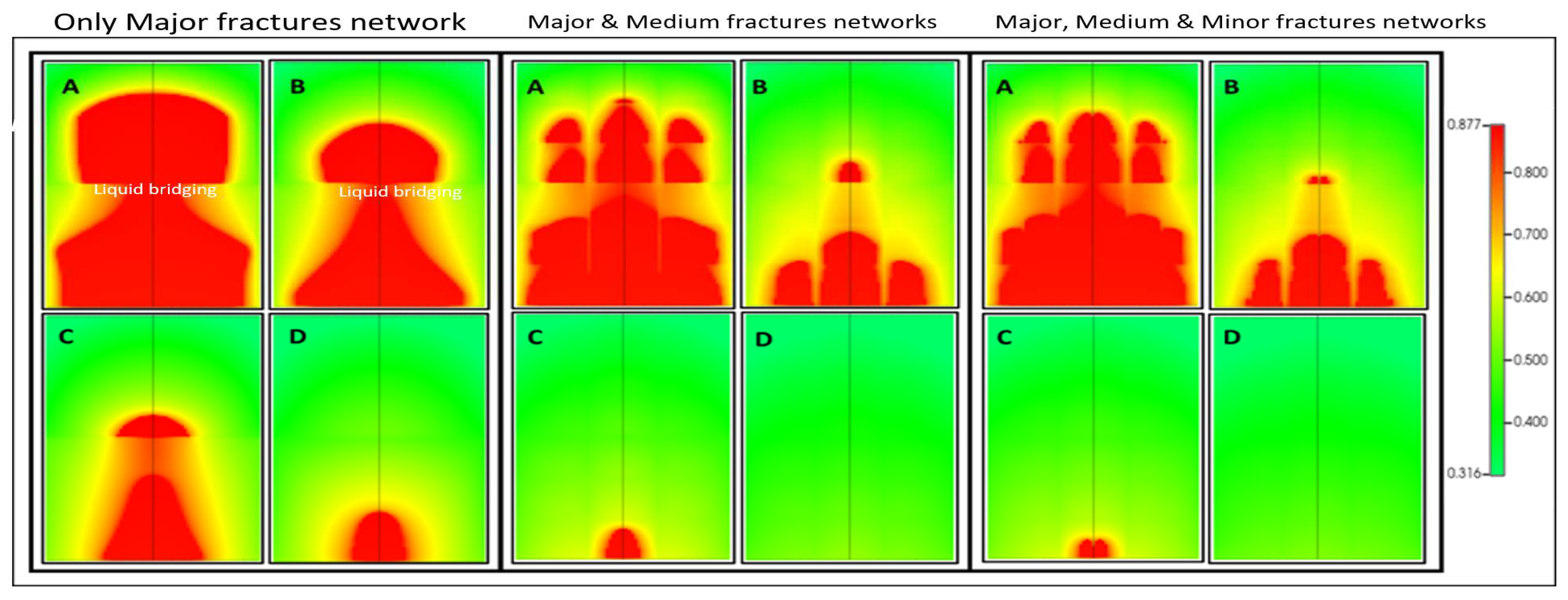
Two vertical slices were used to investigate the impact of the reservoir height and fractures network on the Gas-assisted gravity drainage. Also, to confirm the standard model's observations and capability to capture the production behavior. Comparable recovery performance was observed for the major and non-major fractures, similar to the standard model (one-slice model); however, the effects of capillary continuity and gas breakthrough across different fractures were better observed from the saturation profile. The capillary continuity phenomenon, as experimentally verified by Harimi et al. in 2019, is demonstrated in
Figure 7, where a liquid bridge is observed to form between two sections of the horizontal fractures. The formation of this bridge between the blocks is the cause of the phenomenon. The high oil saturation at the lower section of the upper block crossways the fracture into the upper part of the lower block. When the non-major fractures are not included, the capillary continuity is maintained for a longer time, even after the injection of one pore volume. However, the capillary continuity interrupts faster when the medium and minor fractures are included.
3.2. Foam-Assisted WAG
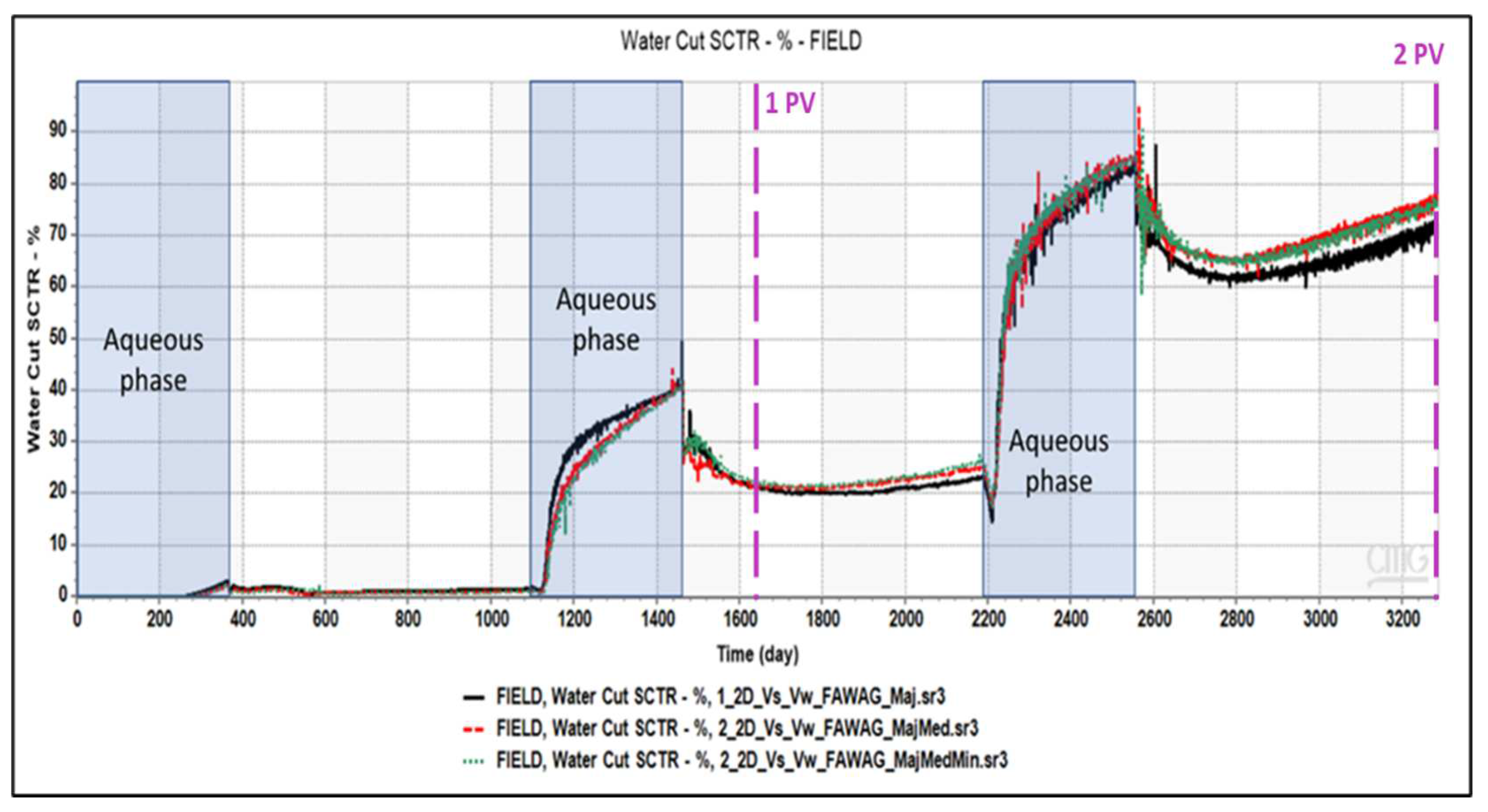
The simulation of the FAWAG process was conducted for the three categories based on horizontal displacement, and the difference between the oil recovery, GOR, water cut, and gas and water saturation was analyzed and compared. The results of the first category are discussed in greater detail because of its greater sensitivity.
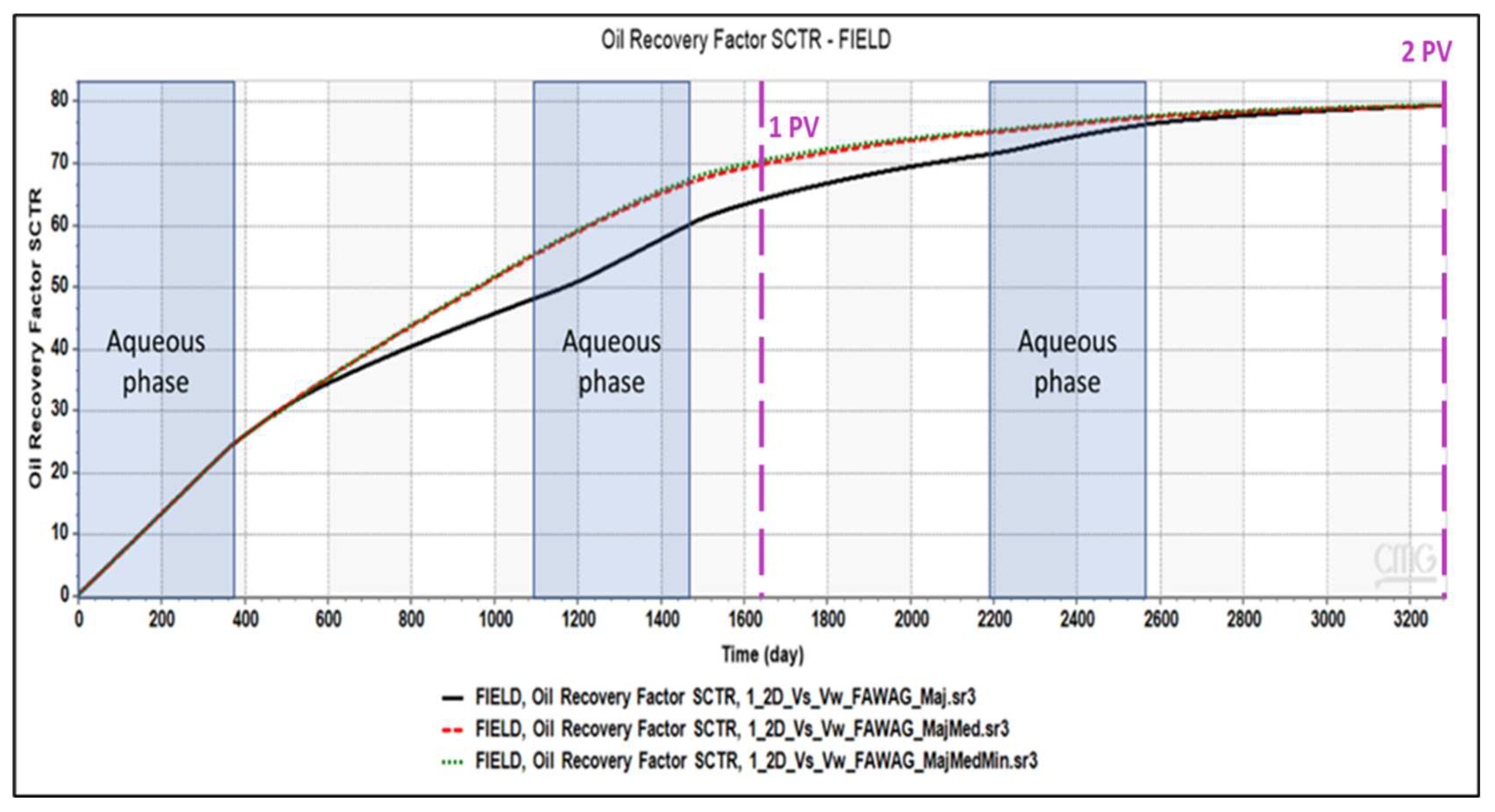
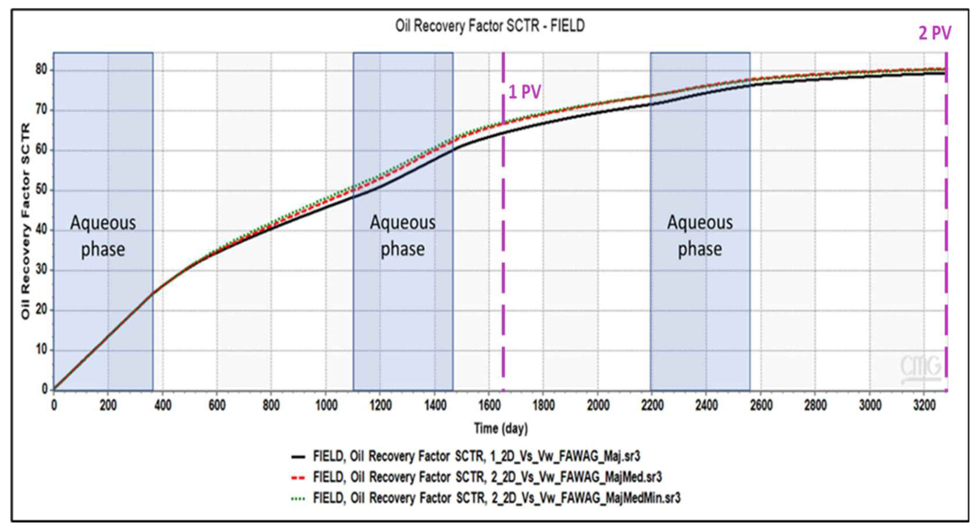
The major difference in the oil recovery was observed between 0.37 pore volumes and 1.58 pore volumes in the first category of fracture networks (
Figure 8). No difference was observed in the first cycle of the aqueous phase (capillary-driven imbibition) and the third gas phase (gravity-driven) cycle when the non-major fractures were included or excluded. It should be noted that in the third aqueous phase, the oil saturation almost reaches the residual oil saturation. Hence, the contribution of the medium fracture network to the recovery is around 5 to 10%. It should be noted that by introducing the non-major fracture networks, the size of the matrix block becomes smaller, which might result in different gravitational and capillary forces interactions since the interaction of these forces depends on the matrix blocks' size and shape [Elfeel et al. 2016].
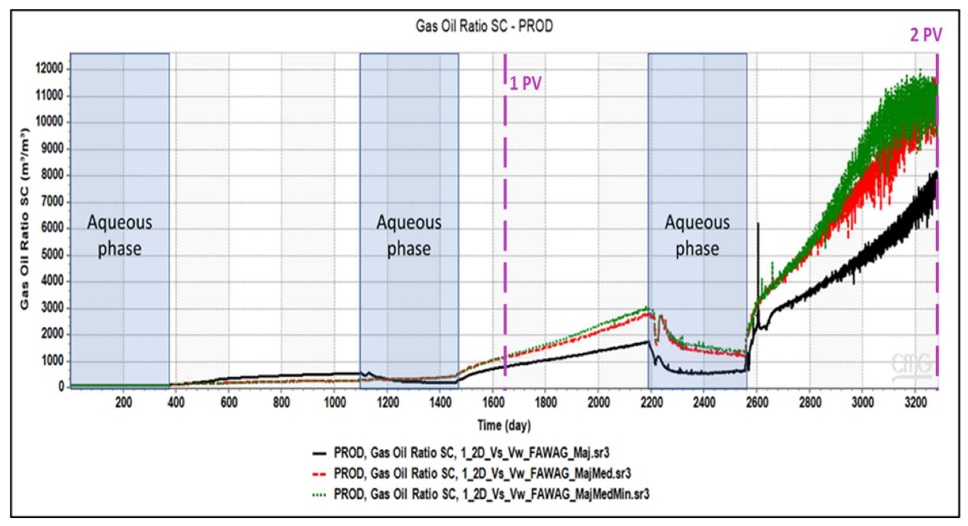
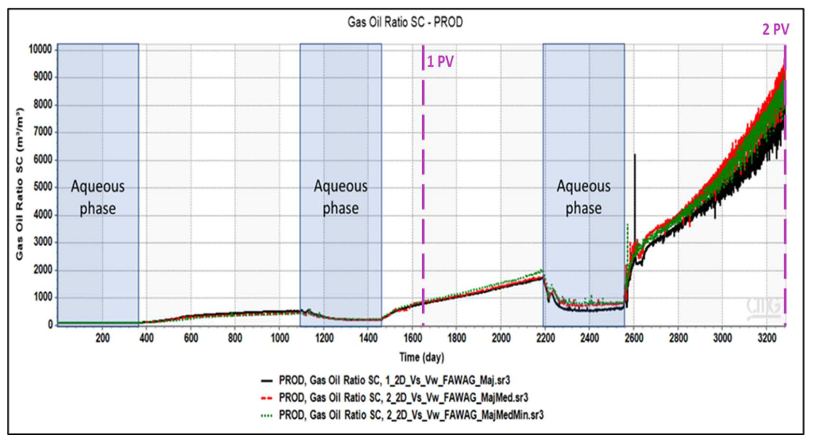
As shown in
Figure 9, the GOR profile over the two cycles shows that excluding the non-major fractures marks a slight overestimation of the produced gas in the first cycle. However, the difference is more noticeable upon the second cycle's commencement, especially at the last gas injection cycle. At the end of the injection period, the major fracture case shows a lower GOR. In comparison, the recovery factor at the end of the second cycle was consistent across all cases. GOR analysis provides a better understanding of fluid behavior and the influence of different fracture types, even in the case of minor fractures with small apertures. Theoretical and experimental evidence has shown a diversion mechanism in which the Foam flows in non-major fractures rather than major fractures within a fractured medium [Kovscek et al., 1995; Haugen et al., 2012].
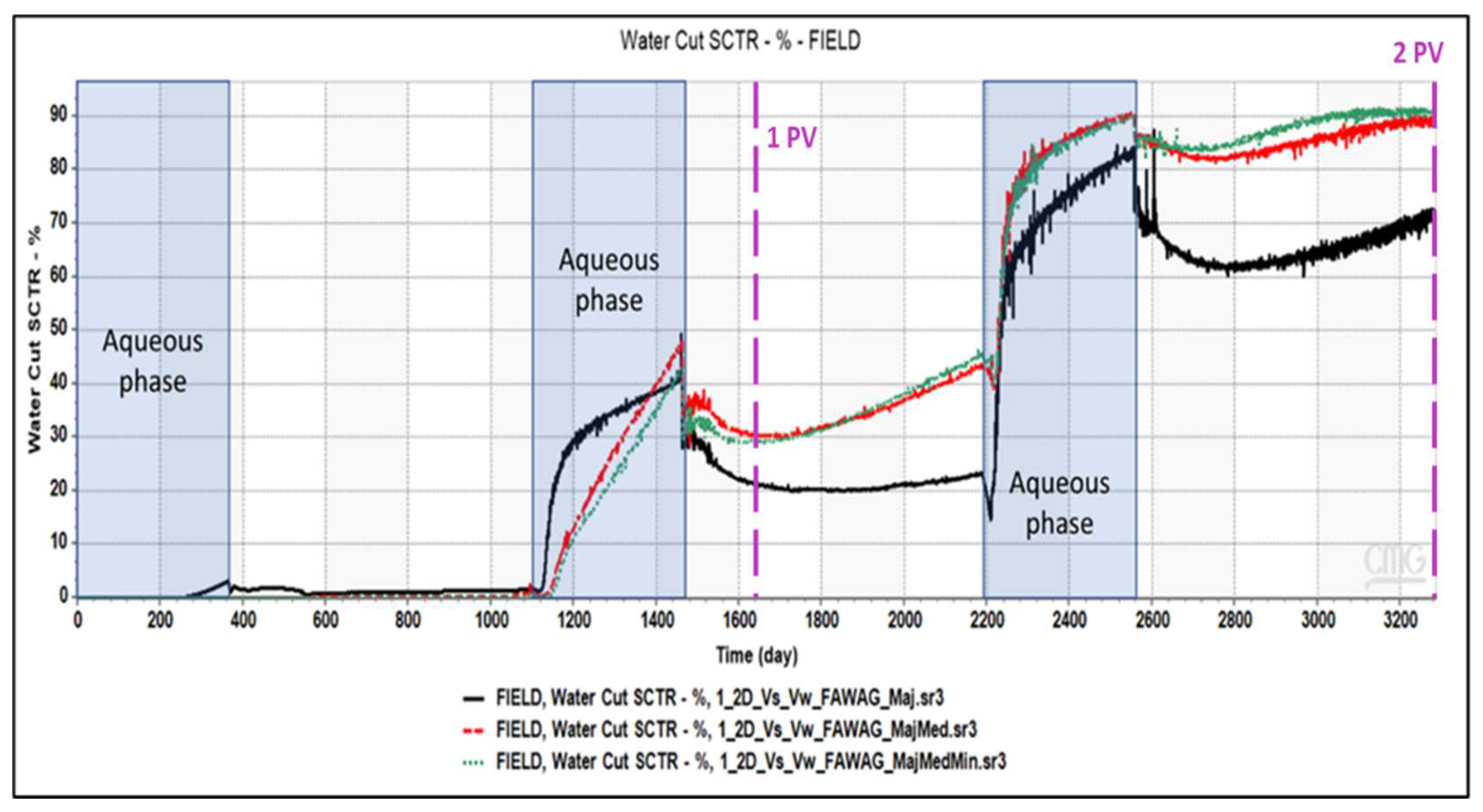
Table 10. Although the first cycle showed little variation in all scenarios, the second cycle, which involved the aqueous phase, led to a noticeable increase in water production in the major fracture network case. However, the opposite trend was observed during the remaining process, where all fractures were included. These observations indicate the fracture network's importance in displacing the injected and produced fluids in the early and late stages of production.
The influence of minor and medium fractures on the simulation of the gas injection process is more evident when incorporated or excluded, as evident from the Gas-Oil Ratio and water cut profiles. Therefore, the gas and water saturation profiles might better describe the observed effluence of the fracture types on production.
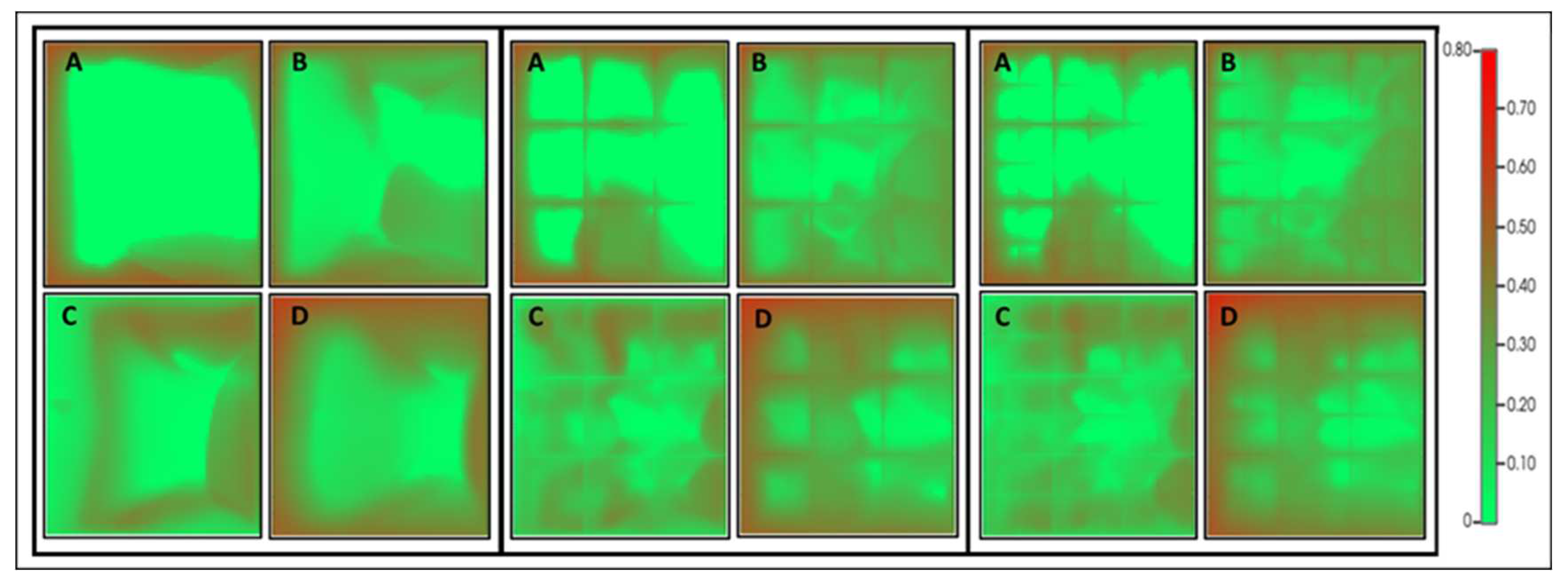
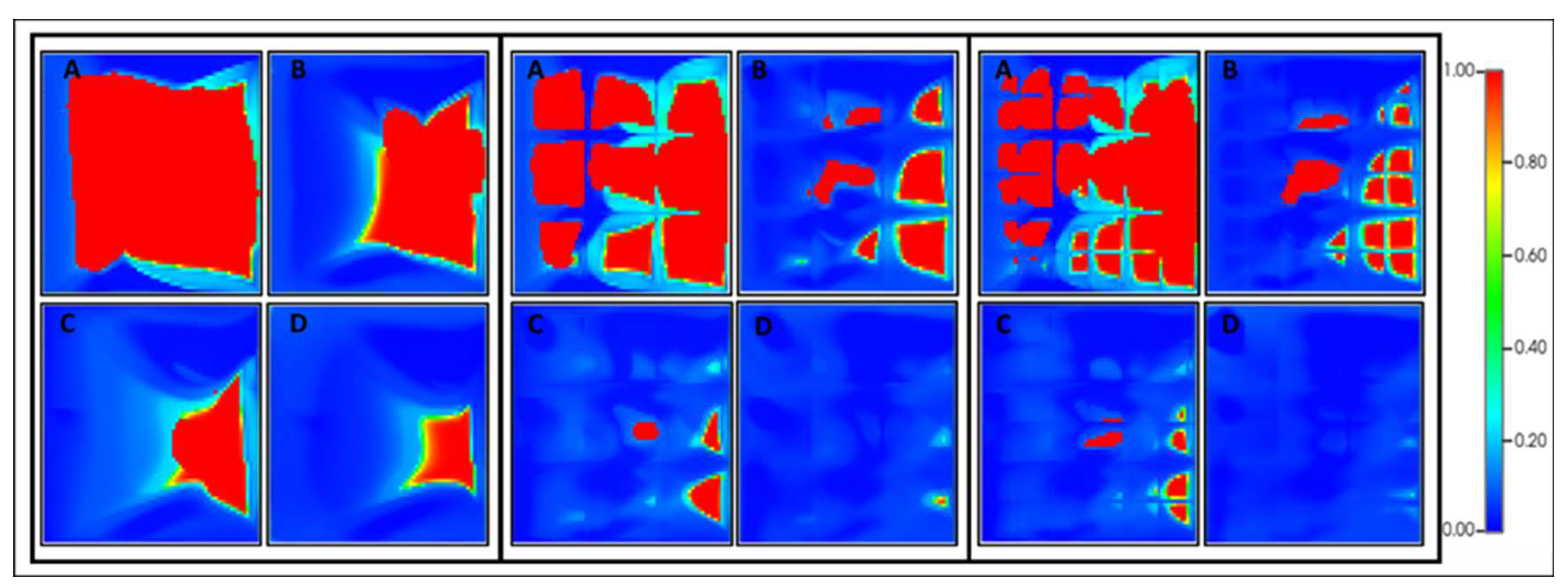
The gas and water saturation demonstrated notable profile differences attributed to governing recovery mechanisms. The gas saturation profile for the FAWAG in the first category for the three cases is shown in
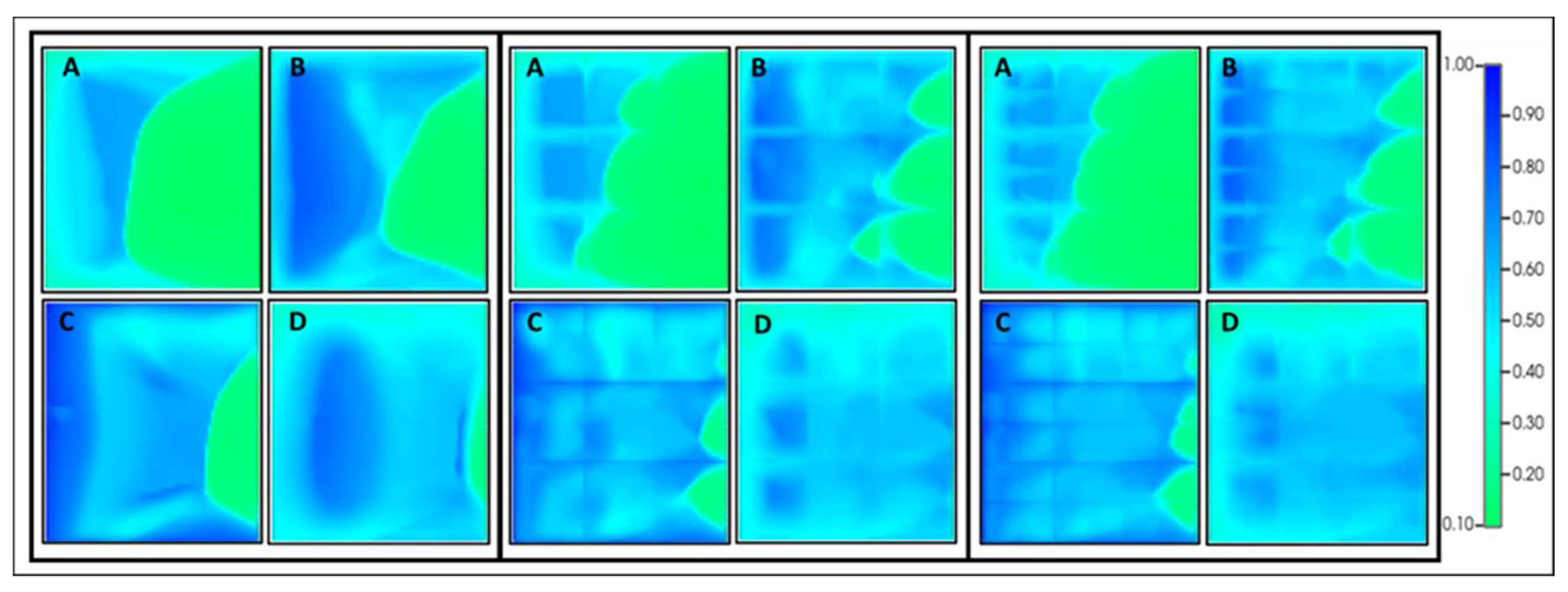
Figure 11. The green and red colors are oil and gas, respectively. As seen in the case of major facture only, the gas phase diffuses from the fracture into the matrix, resulting in the oil flow from the matrix block(s). More gas will be in contact with oil when the medium and minor fractures are included in the model resulting in higher recovery. In the water cycle, the imbibition and re-imbibition are more pronounced when the non-major fractures are included (
Figure 12).
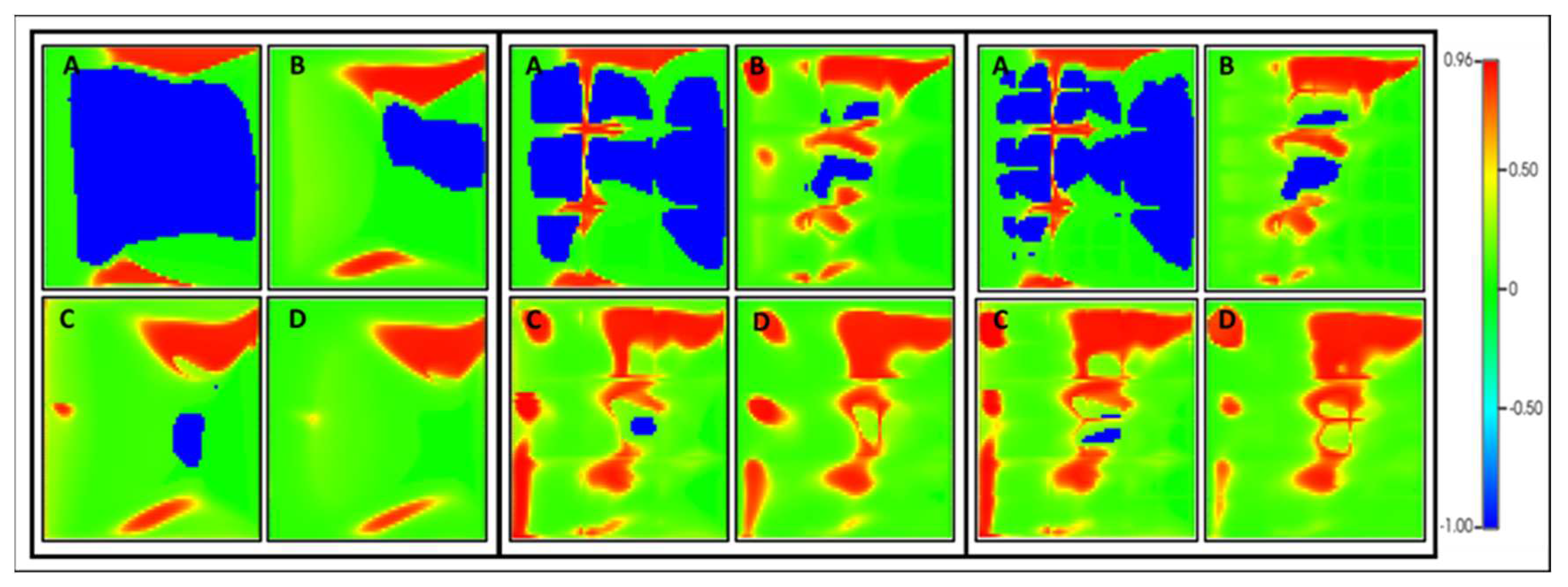
Permeability and dry-out interpolator parameters models are used to examine the degree of foam generation (CMG 2020). Based on the relative permeability indicator, the Foam (blue) is generated first in the major fractures and then in non-major fractures (
Figure 13). It is important to note that blue signifies foam production, while red does not. The gas phase's relative permeability is modified when the necessary condition for foam generation has started forming. The same observation was found when the dry-out interpolator parameter model was used (
Figure 14). In the figure, areas highlighted in red indicate where drying-out has occurred, while green indicates the formation has not experienced any drying-out conditions. The blue regions in the figure correspond to locations where Foam has yet to form.
The second and third categories showed a similar observation regarding oil recovery, GOR, and water cuts. However, the difference compared to the first category was less pronounced, as exemplified by the oil recovery of the second category (
Figure 15).
The GOR behavior difference is noticeable in the last cycle when the Medium and the Minor fractures networks were included. In contrast, no difference was observed in the previous cycles, as shown in
Figure 16.
The GOR and water cut profiles difference of the second category of fracture networks are more noticeable in the last cycle compared to the previous cycles when the Medium and the Minor fractures networks were included (
Figure 16). However, the difference in the water cut is slightly more pronounced than the GOR profile, as shown in
Figure 17.
For the third category, the magnitude of the recovery and the behavior trend was almost the same for the major and non-major fracture cases. Consequently, the Medium and Minor fracture networks exert a lesser influence on the displacement of the injected and produced fluids. This is based on the comparable behavior and magnitude observed for GOR and water cut for these cases. Moreover, the gas and water saturation profiles indicate that the gas flow performance within the fracture networks remained largely unaffected by the non-major fracture networks. As evidenced by the findings from the studied cases, the significance of non-major fracture networks in influencing recovery and fluid behavior during gas injection diminishes from the second to the third category.
3.3. WAG Process
The impact of the fracture types on the WAG process was simulated with the same cycle ratio used for the FAWAG process. The results of both methods for the major and non-major cases of the first category are given in
Figure 18. An underestimation of the foam generation's positive impact in improving recovery is observed for the major fracture case. The influence can only be observed at the injection of more than one pore volume. The impact of the Foam becomes evident when the medium and minor fractures are added to the major fractures, resulting in the inclusion of all fractures. However, minor fractures have minimum impact, and the Medium fractures network largely drives the additional recovery contribution.
As expected, lower oil recovery resulted in the WAG process than the FAWAG process for the three fractured studied cases. However, the positive impact of the Foam was perceived almost only after the second cycle of the aqueous phase injection when the non-major fracture was not included. This observation emphasized the importance of including fracture networks, especially the medium ones, in the recovery process. Hence, the impact of fracture type might be a process depended.
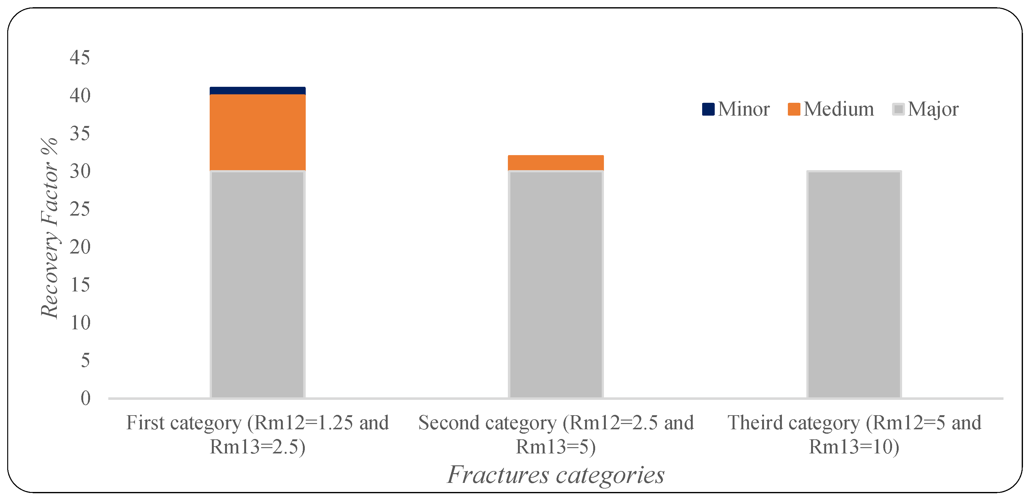
The study findings suggest that the efficacy of the EOR techniques examined is subject to the type and characteristics of the fracture network. Specifically, major fractures exert a greater influence compared to minor ones. The recovery factor for the horizontal displacement mode at one pore volume in the defined dimensionless numbers context is depicted in
Figure 19. The impact of minor fractures on the recovery is only seen at low R
m12 and R
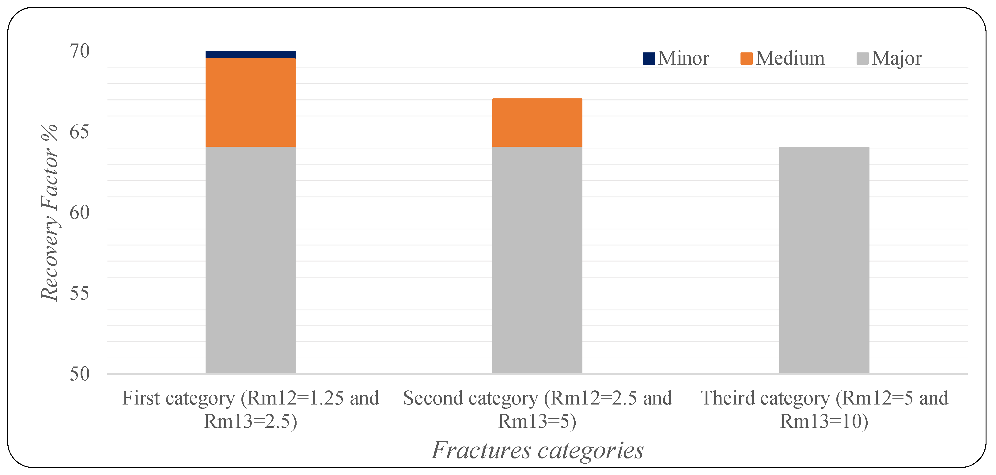
m13, as presented by the first category set. Similar results for the gravity drainage mode. As indicated by the thirst category set, the minor fractures' effect is nil when these two dimensionless numbers increase. The same trend was observed for the FAWAG process, as seen in
Figure 20. However, the impact of the medium fracture on the recovery is more pronounced in the Gas injection process than in the FAWAG process. Around 10% of the gas injection is attributed to the gas injection compared to the 5% for the FAWAG.
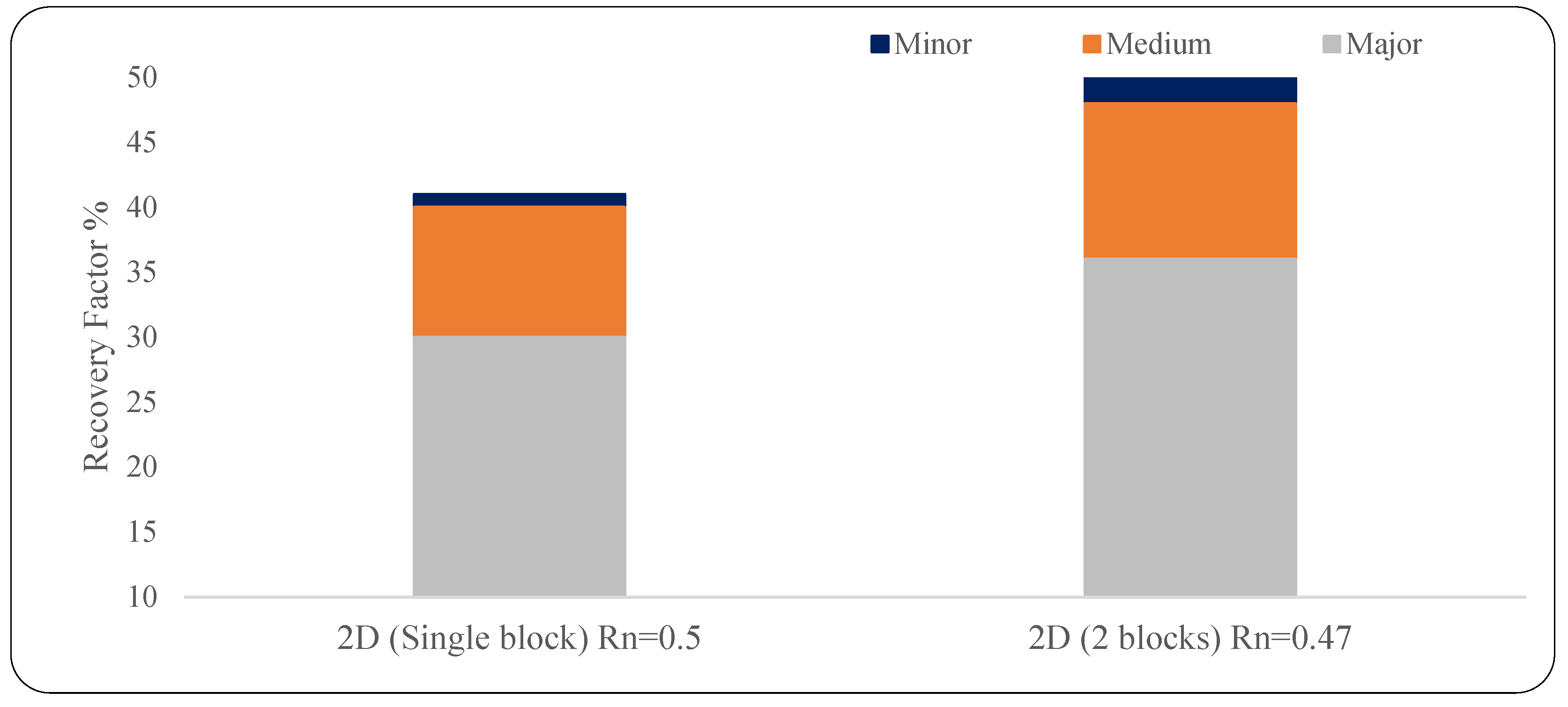
The results of the extended vertical model for the first category in which the fracture intensity (R
n) is increased are given in
Figure 21. When there is an increase in the intensity of major to medium fractures, the significance of other fracture networks decreases. More contribution is attributed to the non-major fractures. A 10% additional recovery results from the medium fractures than the one-slice vertical injection mode. This is related to block height increase and is attributed to the gravity drainage enhancement.
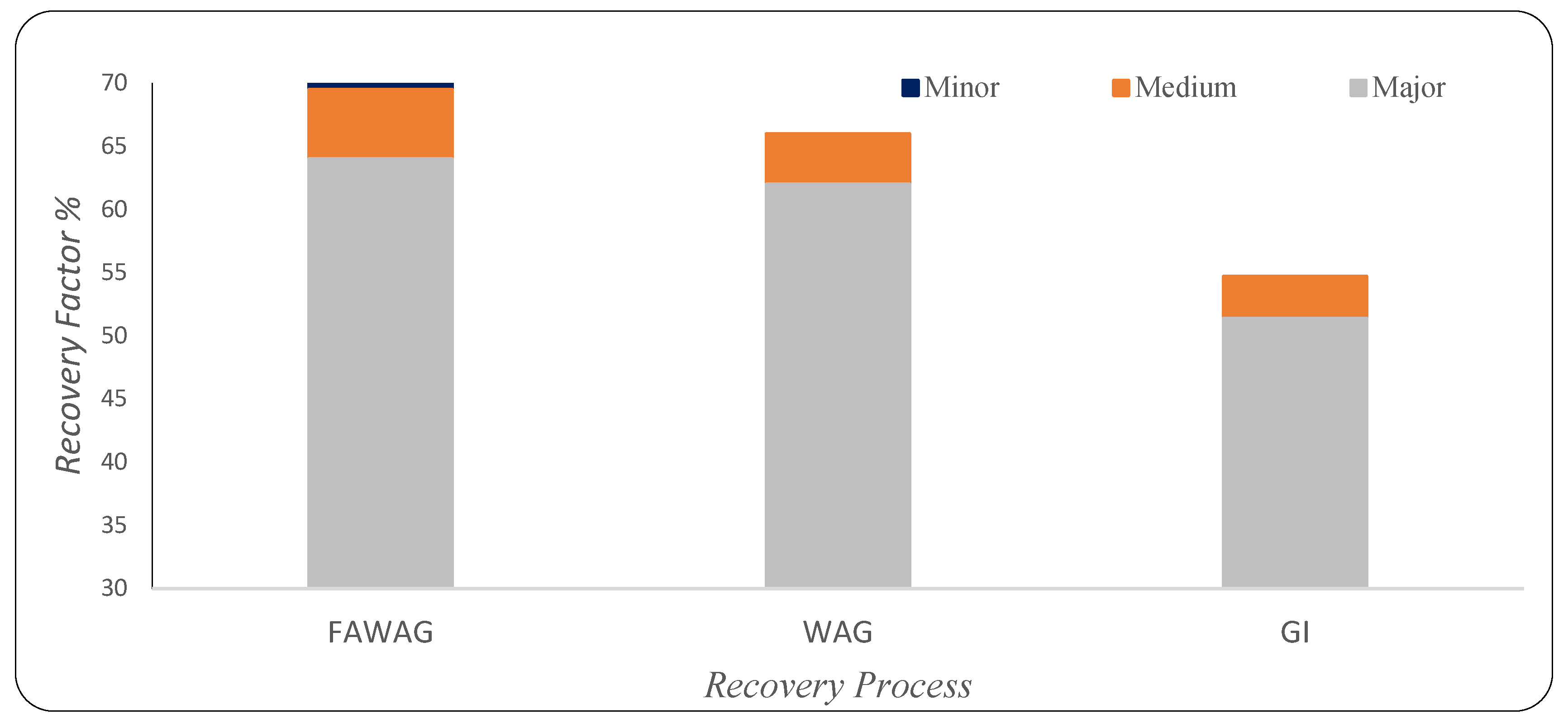
The fracture networks' contribution to the recovery factor for WAG, FAWAG, and GI processes is shown in
Figure 22, where the same oil model was used. The minor fracture type has the minimum recovery contribution to the GI and WAG processes. The recovery is mostly affected by the major and, to a lesser extent, the medium fracture. The equilibrium between capillary/gravity forces in matrix blocks and gravity/viscous forces in fracture control the recovery performance in fractured reservoirs [Kharrat et al., 2021; Heeremans et al., 2006]. The FAWAG process has been reported to be matrix–fracture interaction dependent and more sensitive to permeability contrast, fracture density, and matrix block heights than WAG injection [Kharrat et al.2021]. Furthermore, when evaluating gas-based EOR techniques for gas-invaded regions in fractured reservoirs, Gugl et al. (2022) found that fracture permeability had the greatest impact on oil recovery. Specifically, lower fracture permeability facilitated gas penetration into the matrix blocks. The impact of fracture types can be considered process-depending, possibly due to the different dominance forces for each process. The difference also highlights the fluid properties influence of the fracture network's impact on the EOR process, which needs further investigation.
4. Summary & Conclusion
In recent decades, fractured reservoirs have been a significant challenge in oil and gas reservoir modeling because the properties of fractures and matrix blocks substantially impact the flow performance. The continuous geoscience development in reservoir characterization, especially in fracture network recognition and interpretation, can significantly improve reservoir description and provide a more realistic reservoir model [Wenli et al. 2019]. In addition, the fracture types' contribution to production and the related mechanisms in the primary or later stages of production can be well understood if the interaction between the fracture network and matrix blocks is precisely modeled. Any simplification or homogenization with the assumption of a single set of fracture networks can undermine the production mechanisms, as usually done in the conventional dual-porosity or dual-permeability models [Yan et al., 2016; Xu & Sepehrnoori, 2019; Alalim N., 2022]. The observed results emphasized the impact of fracture networks on the gas-based EOR processes. The impact magnitude for excluding the different types of fracture networks depends on multiple effects that include the recovery process and the reservoir fluids' fluid properties. Also, the literature has established that fracture characteristics and heterogeneity of local apertures do impact foam generation and flow distribution [Osei-Bosu et al., 2016; Shojaei et al., 2019]. Consequently, more consideration is needed for the FAWAG process modeling in fractured reservoirs. In addition, dimensionless numbers used in this work might be further integrated with force-based to evaluate the production mechanisms in fractured reservoirs.
This study investigated the impact of fracture types on the performance of gas-based EOR methods. Major, medium, and minor fracture types were employed for studying the different combination effects of the gas injection, WAG, and FWAG processes. The Medium fractures contributed more to production for the FAWAG process than the WAG and GI based on the studied models, whereas the minor fractures had a minimum effect. According to the analyzed Enhanced Oil Recovery techniques results, the significance of non-major fracture networks diminishes as the major-to-medium and major-to-minor aperture ratios increase. Hence, increasing the aperture ratios decreases the relative importance of medium and minor fractures. However, the degree of impact increases with the height block. Moreover, the increase in the major to medium fracture intensity decreases the non-major impact on the studied processes. The major fractures have the highest impact on the recovery magnitude, while the minor ones have a minor contribution. However, the difference in the gas-oil ratio and water cut is more noticeable than in the oil recovery when the non-major fractures are included.
Author Contributions
Conceptualization, RK; Formal analysis, NA; Investigation, NA; Methodology, RK, and NA; Software, NA; Supervision, RK, and HO; Writing – review & editing, RK, and HO. All authors have read and agreed to the published version of the manuscript.
Funding
This research received no external funding.
Acknowledgments
The authors would like to acknowledge the support provided by the Computer Modeling Group (CMG).
References
- Van Golf-Racht, T. Developments in Petroleum Science, 1982. Fundamentals of Fractured Reservoir Engineering; Elsevier Scientific Publishing Company: Amsterdam, The Netherlands.
- Saidi, A. M, 1987. Reservoir Engineering of Fractured Reservoirs: Fundamental and Practical Aspects; Total: Paris, France.
- Allan, J.; Sun, S.Q. Controls on Recovery Factor in Fractured Reservoirs: Lessons Learned from 100 Fractured Fields. 2003. [Google Scholar] [CrossRef]
- Kharrat, R.; Mahdavi, S.; Ghorbani, D. A Comprehensive EOR Study of a Highly Fractured Matured Field-Case Study. 2012. [Google Scholar] [CrossRef]
- Agada, S. , Geiger, S., & Doster, F., 2016. Wettability, hysteresis, and fracture–matrix interaction during CO2 EOR and storage in fractured carbonate reservoirs. International Journal of Greenhouse Gas Control, 46, 57–75.
- Aljuboori, F.A.; Lee, J.H.; Elraies, K.A.; Stephen, K.D. Effect of fracture characteristics on history matching in the Qamchuqa reservoir: a case study from Iraq. Carbonates Evaporites 2020, 35, 1–20. [Google Scholar] [CrossRef]
- Luo, H.; Mohanty, K.K. Modeling Near-Miscible Gas Foam Injection in Fractured Tight Rocks and Its Challenges. Energies 2021, 14, 1998. [Google Scholar] [CrossRef]
- Kharrat, R. , Ott H., 2023. A Comprehensive Review of Fracture Characterization and Its Impact on Oil Production in Naturally Fractured Reservoirs, Energies vol.16, Issue 8, 16.
- Xu, Z.-X.; Li, S.-Y.; Li, B.-F.; Chen, D.-Q.; Liu, Z.-Y.; Li, Z.-M. A review of development methods and EOR technologies for carbonate reservoirs. Pet. Sci. 2020, 17, 990–1013. [Google Scholar] [CrossRef]
- Kharrat, R.; Zallaghi, M.; Ott, H. Performance Quantification of Enhanced Oil Recovery Methods in Fractured Reservoirs. Energies 2021, 14, 4739. [Google Scholar] [CrossRef]
- Guerriero, V.; Mazzoli, S.; Iannace, A.; Vitale, S.; Carravetta, A.; Strauss, C. A permeability model for naturally fractured carbonate reservoirs. Mar. Pet. Geol. 2013, 40, 115–134. [Google Scholar] [CrossRef]
- Gong, J.; Rossen, W.R. Modeling flow in naturally fractured reservoirs: effect of fracture aperture distribution on dominant sub-network for flow. Pet. Sci. 2016, 14, 138–154. [Google Scholar] [CrossRef]
- Gong, J.; Rossen, W.R. Characteristic fracture spacing in primary and secondary recovery for naturally fractured reservoirs. Fuel 2018, 223, 470–485. [Google Scholar] [CrossRef]
- Gugl, R.; Kharrat, R.; Shariat, A.; Ott, H. Evaluation of Gas-Based EOR Methods in Gas-Invaded Zones of Fractured Carbonate Reservoir. Energies 2022, 15, 4921. [Google Scholar] [CrossRef]
- Elfeel, M.A. , Al-Dhahli, Geiger S., van Dijke M.I.J., 2016. Fracture-matrix interactions during immiscible three-phase flow, Journal of Petroleum Science and Engineering, Volume 143, 171-186.
- Al Karfy, L. , Kharrat R., Ott H., 2021. Mechanistic study of the carbonated smart water in carbonate reservoirs, Greenhouse Gases, Science and Technology, Greenhouse Gases, Science and technology J., vol. 11, 661-681.
- Pejic M., Kharrat; Kadkhodaaie, A. ; Azizmohammadi; Ott H., 2022. Impact of fracture types on the oil recovery in naturally fractured reservoirs. Energies 5(19), 7321.
- Mogensen, K.; Masalmeh, S. A review of EOR techniques for carbonate reservoirs in challenging geological settings. J. Pet. Sci. Eng. 2020, 195, 107889. [Google Scholar] [CrossRef]
- Silva, R.R.; Maini, B. Evaluation of Gas Assisted Gravity Drainage GAGD in Naturally Fractured Reservoirs NFR. 2016. [Google Scholar] [CrossRef]
- Heeremans, J. , Esmaiel, T. & Kruijsdijk, C. V., 2006. Feasibility Study of WAG Injection in Naturally Fractured Reservoirs, SPE 100034, p. 10.
- Gbadamosi, A.O; Kiwalabye, J.; Juni, R.; Augustine, A. 2018. A review of gas enhanced oil recovery schemes used in the North Sea, Journal of Petroleum Exploration and Production Technology 8:1373–1387.
- Ayoub, M.; Saaid, I.B.; Shabib-asl, A. , 2014. Comprehensive Review of Foam Application during Foam Assisted Water Alternating Gas (FAWAG) Method Research Journal of Applied Sciences, Engineering and Technology 8(17): 1896-1904, 2014.
- CMG. 2020. GEM 2020.11 User Guide. Computer Modelling Group Ltd.
- Bourbiaux, B. , 2010. Fractured Reservoir Simulation: A Challenging and Rewarding Issue. Oil & Gas Science and Technology – Revue de l’Institut Français Du Pétrole, 65(2), 227–238.
- Kasiri, N.; Bashiri, A. Status of Dual-Continuum Models for Naturally Fractured Reservoir Simulation. Pet. Sci. Technol. 2011, 29, 1236–1248. [Google Scholar] [CrossRef]
- Lei, Q. , Latham, J.-P., & Tsang, C.-F., 2017. The use of discrete fracture networks for modeling coupled geomechanical and hydrological behavior of fractured rocks. Computers and Geotechnics, 85, 151–176.
- Bosma, S.; Hajibeygi, H.; Tene, M.; Tchelepi, H.A. Multiscale finite volume method for discrete fracture modeling on unstructured grids (MS-DFM). J. Comput. Phys. 2017, 351, 145–164. [Google Scholar] [CrossRef]
- Wong, D.L.Y.; Doster, F.; Geiger, S.; Francot, E.; Gouth, F. Fluid Flow Characterization Framework for Naturally Fractured Reservoirs Using Small-Scale Fully Explicit Models. Transp. Porous Media 2020, 134, 399–434. [Google Scholar] [CrossRef]
- Kovscek, A.R.; Tretheway, D.C.; Persoff, P. , Radke, C.J., 1995. Foam flow through a transparent rough-walled rock fracture Journal of Petroleum Science and Engineering, Volume 13, Issue 2, J, 75-86.
- Haugen. ; Fernø, M.A.; Graue, A.; Bertin, H.J. Experimental Study of Foam Flow in Fractured Oil-Wet Limestone for Enhanced Oil Recovery. SPE Reserv. Evaluation Eng. 2012, 15, 218–228. [Google Scholar] [CrossRef]
- Ma, K.; Ren, G.; Mateen, K.; Morel, D.; Cordelier, P. Modeling Techniques for Foam Flow in Porous Media. SPE J. 2015, 20, 453–470. [Google Scholar] [CrossRef]
- Alalim, N. , 2022. Impact of Fractures Networks on Gas-based EOR Methods, Montanuniverstat, MSc.
- Harimi, B.; Masihi, M.; Ghazanfari, M.H. Characterization of Liquid Bridge in Gas/Oil Gravity Drainage in Fractured Reservoirs. 2019; 8, 73–91. [Google Scholar] [CrossRef]
- Wenli, Y.; Sharifzadeh, M.; Yang, Z.; Xu, G.; Fang, Z. Assessment of fracture characteristics controlling fluid flow performance in discrete fracture networks (DFN). J. Pet. Sci. Eng. 2019, 178, 1104–1111. [Google Scholar] [CrossRef]
- Xu, Y.; Sepehrnoori, K. Development of an Embedded Discrete Fracture Model for Field-Scale Reservoir Simulation With Complex Corner-Point Grids. SPE J. 2019, 24, 1552–1575. [Google Scholar] [CrossRef]
- Yan, X.; Huang, Z.; Yao, J.; Li, Y.; Fan, D. An efficient embedded discrete fracture model based on mimetic finite difference method. J. Pet. Sci. Eng. 2016, 145, 11–21. [Google Scholar] [CrossRef]
- Shojaei, M.J.; de Castro, A.R.; Méheust, Y.; Shokri, N. Dynamics of foam flow in a rock fracture: Effects of aperture variation on apparent shear viscosity and bubble morphology. J. Colloid Interface Sci. 2019, 552, 464–475. [Google Scholar] [CrossRef] [PubMed]
- Osei-Bonsu, K.; Shokri, N.; Grassia, P. Fundamental investigation of foam flow in a liquid-filled Hele-Shaw cell. J. Colloid Interface Sci. 2016, 462, 288–296. [Google Scholar] [CrossRef] [PubMed]
Figure 1.
Model configuration with three fracture types.
Figure 1.
Model configuration with three fracture types.
Figure 2.
workflow of the study for the effect of the fracture's networks.
Figure 2.
workflow of the study for the effect of the fracture's networks.
Figure 3.
Oil saturation profile for gas injection process left: Only Major fractures network, Middle: Major & Medium fractures networks, right: Major, Medium & Minor fractures networks, at A:0.5., B:1, C:1.5 PV, 2PV (oil in red & gas in green color).
Figure 3.
Oil saturation profile for gas injection process left: Only Major fractures network, Middle: Major & Medium fractures networks, right: Major, Medium & Minor fractures networks, at A:0.5., B:1, C:1.5 PV, 2PV (oil in red & gas in green color).
Figure 4.
Oil Recovery factor for gas injection process ( Horizontal mode-first category).
Figure 4.
Oil Recovery factor for gas injection process ( Horizontal mode-first category).
Figure 5.
GOR for gas injection process ( Horizontal mode-first category).
Figure 5.
GOR for gas injection process ( Horizontal mode-first category).
Figure 6.
First category oil saturation profile of gas injection process (Gravity drainage mode) left: Only Major fractures network, Middle: Major & Medium fractures networks, Right: Major, Medium & Minor fractures networks, at A:0.5 PV, B:1 PV, C:1.5 PV, D:2 PV (oil in red & gas in green color). .
Figure 6.
First category oil saturation profile of gas injection process (Gravity drainage mode) left: Only Major fractures network, Middle: Major & Medium fractures networks, Right: Major, Medium & Minor fractures networks, at A:0.5 PV, B:1 PV, C:1.5 PV, D:2 PV (oil in red & gas in green color). .
Figure 7.
First category oil saturation profile of gas injection process (Extended Gravity drainage mode). of the first category at A:0.5 PV, B:1 PV, C:1.5 PV, and D:2 PV (oil in red & gas in green color).
Figure 7.
First category oil saturation profile of gas injection process (Extended Gravity drainage mode). of the first category at A:0.5 PV, B:1 PV, C:1.5 PV, and D:2 PV (oil in red & gas in green color).
Figure 8.
Oil Recovery vs. Time of the FAWAG process in the first category.
Figure 8.
Oil Recovery vs. Time of the FAWAG process in the first category.
Figure 9.
GOR vs. Time of the FAWAG process in the first category.
Figure 9.
GOR vs. Time of the FAWAG process in the first category.
Figure 10.
Water cut vs. Time of the FAWAG process of the first category.
Figure 10.
Water cut vs. Time of the FAWAG process of the first category.
Figure 11.
Profile of the gas saturation of FAWAG process in the first category left: Only Major fractures network, Middle: Major & Medium fractures networks, right: Major, Medium & Minor fractures networks, at A:0.5 PV, B:1 PV, C:1.5 PV, D:2 PV(gas in red & oil in green color).
Figure 11.
Profile of the gas saturation of FAWAG process in the first category left: Only Major fractures network, Middle: Major & Medium fractures networks, right: Major, Medium & Minor fractures networks, at A:0.5 PV, B:1 PV, C:1.5 PV, D:2 PV(gas in red & oil in green color).
Figure 12.
Profile of water saturation of FAWAG process in the first category left: Only Major fractures network, Middle: Major & Medium fractures networks, right: Major, Medium & Minor fractures networks, at A:0.5 PV, B:1 PV, C:1.5 PV, D:2 PV (water in blue & oil in green color). .
Figure 12.
Profile of water saturation of FAWAG process in the first category left: Only Major fractures network, Middle: Major & Medium fractures networks, right: Major, Medium & Minor fractures networks, at A:0.5 PV, B:1 PV, C:1.5 PV, D:2 PV (water in blue & oil in green color). .
Figure 13.
Profile of the relative permeability interpolator (in blue) of FAWAG process in the first category left: Only Major fractures network, Middle: Major & Medium fractures networks, right: Major, Medium & Minor fractures networks, at A:0.5 PV, B:1 PV, C:1.5 PV, D:2 PV.
Figure 13.
Profile of the relative permeability interpolator (in blue) of FAWAG process in the first category left: Only Major fractures network, Middle: Major & Medium fractures networks, right: Major, Medium & Minor fractures networks, at A:0.5 PV, B:1 PV, C:1.5 PV, D:2 PV.
Figure 14.
Profile of the dry-out interpolation parameter (in red) of FAWAG process in the first category left: Only Major fractures network, Middle: Major & Medium fractures networks, Right: Major, Medium & Minor fractures networks, at A:0.5 PV, B:1 PV, C:1.5 PV, D:2 PV.
Figure 14.
Profile of the dry-out interpolation parameter (in red) of FAWAG process in the first category left: Only Major fractures network, Middle: Major & Medium fractures networks, Right: Major, Medium & Minor fractures networks, at A:0.5 PV, B:1 PV, C:1.5 PV, D:2 PV.
Figure 15.
Oil Recovery vs. Time of the FAWAG process (Second category of fractures networks).
Figure 15.
Oil Recovery vs. Time of the FAWAG process (Second category of fractures networks).
Figure 16.
GOR vs. Time of the FAWAG process (Second category of fractures networks).
Figure 16.
GOR vs. Time of the FAWAG process (Second category of fractures networks).
Figure 17.
Water cut vs. Time of the FAWAG process (Second category of fractures networks).
Figure 17.
Water cut vs. Time of the FAWAG process (Second category of fractures networks).
Figure 18.
for FAWAG & WAG Oil Recovery factor in the first category of fractures networks.
Figure 18.
for FAWAG & WAG Oil Recovery factor in the first category of fractures networks.
Figure 19.
Gas injection recovery contribution of the three categories at one pore volume (Horizontal displacement: Rn=0.5).
Figure 19.
Gas injection recovery contribution of the three categories at one pore volume (Horizontal displacement: Rn=0.5).
Figure 20.
FAWAG recovery contribution of the three categories at one pore volume (Rn=0.5).
Figure 20.
FAWAG recovery contribution of the three categories at one pore volume (Rn=0.5).
Figure 21.
Gas injection recovery contribution of the fractures types of the verticle and the extended 2D models.
Figure 21.
Gas injection recovery contribution of the fractures types of the verticle and the extended 2D models.
Figure 22.
Fractures networks' effect on WAG, FAWAG, and GI recovery (Rn=0.50).
Figure 22.
Fractures networks' effect on WAG, FAWAG, and GI recovery (Rn=0.50).
Table 1.
Models configurations and description.
Table 1.
Models configurations and description.
| Model name |
Dimensions |
Grids number in each direction |
Porosity |
Permeability |
| meter |
% |
mD |
| X |
Y |
Z |
X |
Y |
Z |
- |
X |
Y |
Z |
| 2D Vertical slice |
15 |
1 |
15 |
67 |
1 |
67 |
0.2 |
1 |
1 |
1 |
| Extended 2D Vertical slice |
15 |
1 |
30 |
67 |
1 |
134 |
0.2 |
1 |
1 |
1 |
Table 2.
Properties of the three categories.
Table 2.
Properties of the three categories.
| Properties |
Fractures Aperture |
Dimensionless numbers |
Fractures Permeability |
| mm |
Darcy |
| Category |
Major |
Medium |
Minor |
Rm12
|
Rm13
|
Major |
Medium |
Minor |
| 1 |
2.00 |
1.60 |
0.80 |
1.25 |
2.50 |
4.00 |
2.56 |
0.64 |
| 2 |
2.00 |
0.80 |
0.40 |
2.50 |
5.00 |
4.00 |
0.64 |
0.16 |
| 3 |
2.00 |
0.40 |
0.20 |
5.00 |
10.00 |
4.00 |
0.16 |
0.04 |
Table 3.
Oil Fluid properties used for gas injection & Foam.
Table 3.
Oil Fluid properties used for gas injection & Foam.
| Gas injection fluid model |
Foam Model CMG |
| Parameter |
Value |
unit |
Component |
Mole |
| GOR |
155 |
m3/m3
|
C1 |
0.50 |
| Pb |
362.6 |
psi |
C3 |
0.03 |
| Bg |
0.0043 |
m3/sm3
|
C6 |
0.07 |
| Bo |
1.42 |
m3/sm3
|
C10 |
0.20 |
| µg |
0.042 |
cp |
C15 |
0.15 |
| µo |
0.76 |
cp |
C20 |
0.05 |
|
Disclaimer/Publisher’s Note: The statements, opinions and data contained in all publications are solely those of the individual author(s) and contributor(s) and not of MDPI and/or the editor(s). MDPI and/or the editor(s) disclaim responsibility for any injury to people or property resulting from any ideas, methods, instructions or products referred to in the content. |
© 2023 by the authors. Licensee MDPI, Basel, Switzerland. This article is an open access article distributed under the terms and conditions of the Creative Commons Attribution (CC BY) license (http://creativecommons.org/licenses/by/4.0/).
