1. Introduction
Lattice structures are cellular structures consisting of interconnected struts [
1]. Each lattice structure is based on a lattice frame, also denoted as a wireframe, which describes with nodes and edges the inherent topological skeleton. The latter can either be irregular or consists of periodically repeated unit cells. Besides the interconnections and coordinates described by the lattice frame, the cross section shapes and radii of the struts are local shape parameters of lattice structures.
Lattice structures find use in various disciplines, often in connection with additive manufacturing, reaching from architecture and mechanical engineering to health care [
2,
3]. Applications include medical implants [
4], crash boxes [
5] and heat sinks [
6]. Lattice structures are particularly suitable for lightweight designs due to their high stiffness-weight ratio [
3] and find therefore use in components that are designed for aeronautics and space applications [
7,
8]. In [
8], additively manufactured lattice structures are used as cellular infills in areas where the topology optimization of the discussed component recommends material densities between void and solid. Even entire components consisting of lattice structures are derived in [
9] from topology optimization results. To solidify the proposed (often irregular) wireframes in CAD software, an automated algorithm is required. Many commercial CAD software tools rely on spline-based surface patches that are exactly parametrizable by their control points. To integrate the design of lattice structure infills in the design process of the surrounding component, a method based on surface patches is favourable. Having a component design based on splines is also advantageous for additive manufacturing, because it enables local manipulations i.e., to remove large overhangings and to create support-free printable structures.
Besides the wireframe topology, smooth node transitions, also called filleted nodes, are an important aspect of lattice structure design as they can improve the structural response to loadings by reducing local stress concentrations and increasing the stiffness [
10,
11]. Also the realizability of strut radii gradients, usefull for further tailoring the lattice structure to an intended use, is improved in smooth lattice structures, according to [
12].
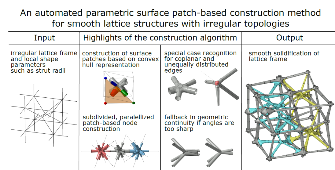
Several methods, that are discussed in
Section 2, have been developed to construct smooth lattice structures. However, no algorithm is available that automatizes the surface-patch based construction for irregular lattice topologies. Therefore, the objective of this work was to develop an surface-patch based algorithm without manual construction steps that is able to construct smooth lattice structures based on given lattice frames and strut radii for as general cases as possible. The method expanded on in this work has been applied by the authors for constructing a planar lattice as an infill for a lightweight structure in [
8]. The algorithm is implemented in the commercial software CATIA, however it can be used in any computer aided design software that supports the three basic surface construction methods discussed in
Section 3.
2. Related Work
Smooth lattice structures are constructed using polygon mesh methods [
11,
13,
14], iso-surface methods [
10,
15,
16] and surface patch methods [
12,
17]. Their commonality is the construction of the lattice structures surface instead of a solid object. In [
11,
13,
14], lattice structures are described with polygon meshes. Starting with simple mesh models, subdivision schemes are applied to refine the mesh leading to smooth strut intersections. The main disadvantage of polygon mesh based approaches is the inexact parametrizability of local shape parameters such as strut radii, as discussed in [
11]. In [
10,
16], the definition of lattice structures with iso-surfaces is based on surface equations that map the three dimensional space to the set of real numbers. The lattice structure is defined by the set of points that is mapped to values smaller or equal to zero. Thus, the zero-value iso-surface describes the lattice structures’ surface. Thereby, the lattice structures’ smoothness is inherited from the surface equations. Construction methods assembling the lattice structures’ surface with surface patches are presented in [
12,
17]. Boundary conditions ensure smooth transition between patches. However, the available algorithms for this method either require manual construction steps or are restricted to periodic topologies.
The complex task of smoothly solidifying a wide range of different nodes in lattice frames with irregular topology is either solved manually [
17] or with convex hull algorithms [
11,
13,
14].
Regarding the possibility to respect different local shape parameters such as strut radii gradients within the lattice structure, all of the reviewed methods face limitations. Polygon-mesh based approaches allow different strut radii in the definition of the initial mesh model. According to [
11], the application of subdivision schemes during the smoothing process leads to deformations of these initial radii and cross section shapes. Therefore, parameters have to be selected carefully or manually and extensive post-processing is required. Furthermore, an exact parametrization is impossible. In [
10], an iso-surface construction method with varying strut radii is discussed. On the basis of surface equations, this approach only allows radius gradients along vectors. Consequently, the radii are not separately parametrizable for each strut. Contrary to the preceding approaches, surface patch methods offer the possibility of exact strut radii parametrization, as it is shown in [
12]. Nevertheless, the algorithm developed in [
12] is restricted to periodic lattice structures with repeated unit cells.
So far the only known surface patch-based approach [
17] for constructing irregular lattices with smooth surfaces is based solely on manual construction steps. The here presented work is focused on fully automating this process with using a convex hull algorithm in conjunction with similar but automated construction steps as well as automated special case handling for non-standard inputs.
3. Surface Construction Methods
The lattice structure is to be constructed as a
free-form surface [
18], meaning that it does not belong to a more easily recognized class of surfaces like cylinders or spheres due to the desired smoothness and irregular topology. According to [
18], free-form surfaces are here constructed using a segmentation into local parametrizations of the surface, also denoted as
surface patches [
19]. To ensure smoothness,
-continuity [
20] is imposed between neighbouring patches. Within the proposed algorithm, surface patch construction methods for the following three base cases are required:
Given two curves
and
, the
ruled surface [
20]
linearly interpolates
b and
c.
Figure 1a shows an example for the latter. In the developed algorithm, they are used for the definition of cross-boundary tangent conditions to ensure
-continuity of further constructed surface patches.
If the ruled surface matches additionally cross-boundary tangent conditions along
and
, it is denoted as
-continuous ruled surface. An example is illustrated in
Figure 1b. A method to impose geometric continuity on ruled surfaces can be found in [
21]. This type of surface patch is used for the construction of struts and for smooth transitions between strut ends that converge to the same node.
Given a set of
N boundary curves
forming a loop, a surface patch filling the region inside the loop and meeting cross-boundary tangent conditions is denoted as
-continuous N-patch. In
Figure 1c, a
-continuous 3-patch is sketched. Algorithms to construct this type of surface patch can be found in [
22,
23,
24]. They are used in the lattice construction algorithm to fill regions between strut ends and their smooth transitions.
4. Lattice Construction Algorithm
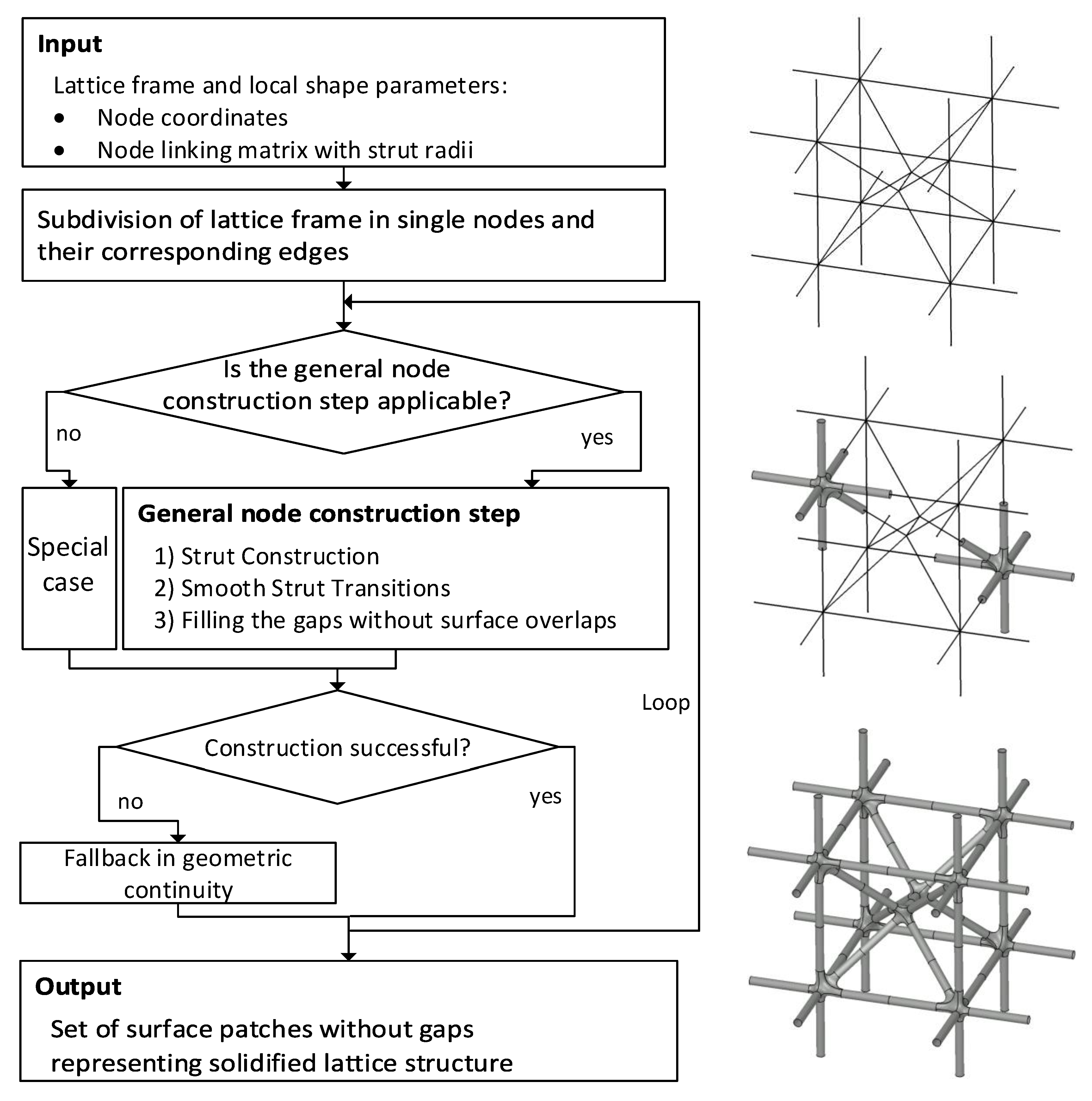
The algorithm is summarized in the flow chart (
Figure 2). First, the inputs, given by the lattice frame and local shape parameters are read. Then, the lattice frame is subdivided in order to split the construction task in small, independent and parallelizable pieces. Afterwards, for each of the latter the applicability of the general construction method is checked. Otherwise, a suitable special case workaround is considered. In any case, the construction is tested of failures and a fallback in geometric continuity is applied if necessary. A set of surface patches that describes the surface of the solidified lattice structure is given as an output. The algorithm is implemented in CATIA but not limited to this software. It can be reimplemented in any CAD software that enables the construction of the three types of surfaces defined in
Section 3.
4.1. Input and Output
The input to the proposed construction method consists of the lattice frame and of strut radii. For each node the associated coordinates are required and for each edge two radii are to be defined, one per end. Thus, lattice structures with thickness gradients can be constructed. The coordinates as well as the linking and radii informations are stored in matrices, which could be generated by any lattice frame design algorithm. In this work, they are assumed to be given. The developed algorithm solidifies the lattice frame by generating a set of surface patches that describes the lattice structures’ surface without gaps.
4.2. Subdivision of the Lattice Structure
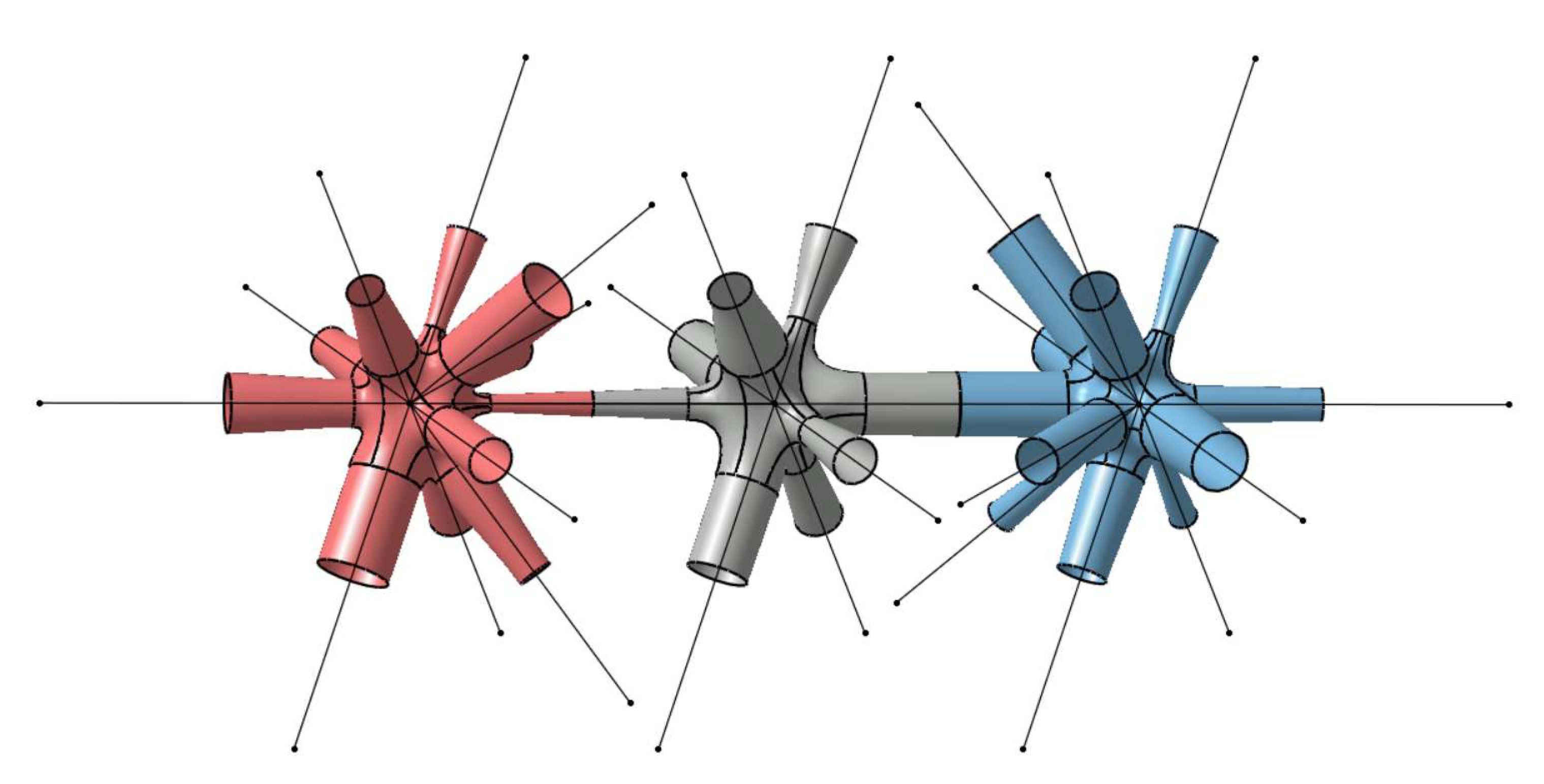
The developed method constructs the surface of the lattice structure iteratively. In each step a smooth transition corresponding to one node of the lattice frame and half of the struts converging to that node are created (
Figure 3). Combining the construction of transitions and struts in each step guarantees the availability of the boundary conditions that are required for
-continuous transitions. However, the steps are independent of each other and can be parallelized. Furthermore, parameter adjustments, special case workarounds and fall-back mechanisms can be applied locally in case the general node construction method fails to construct the transition.
4.3. General Node Construction Step
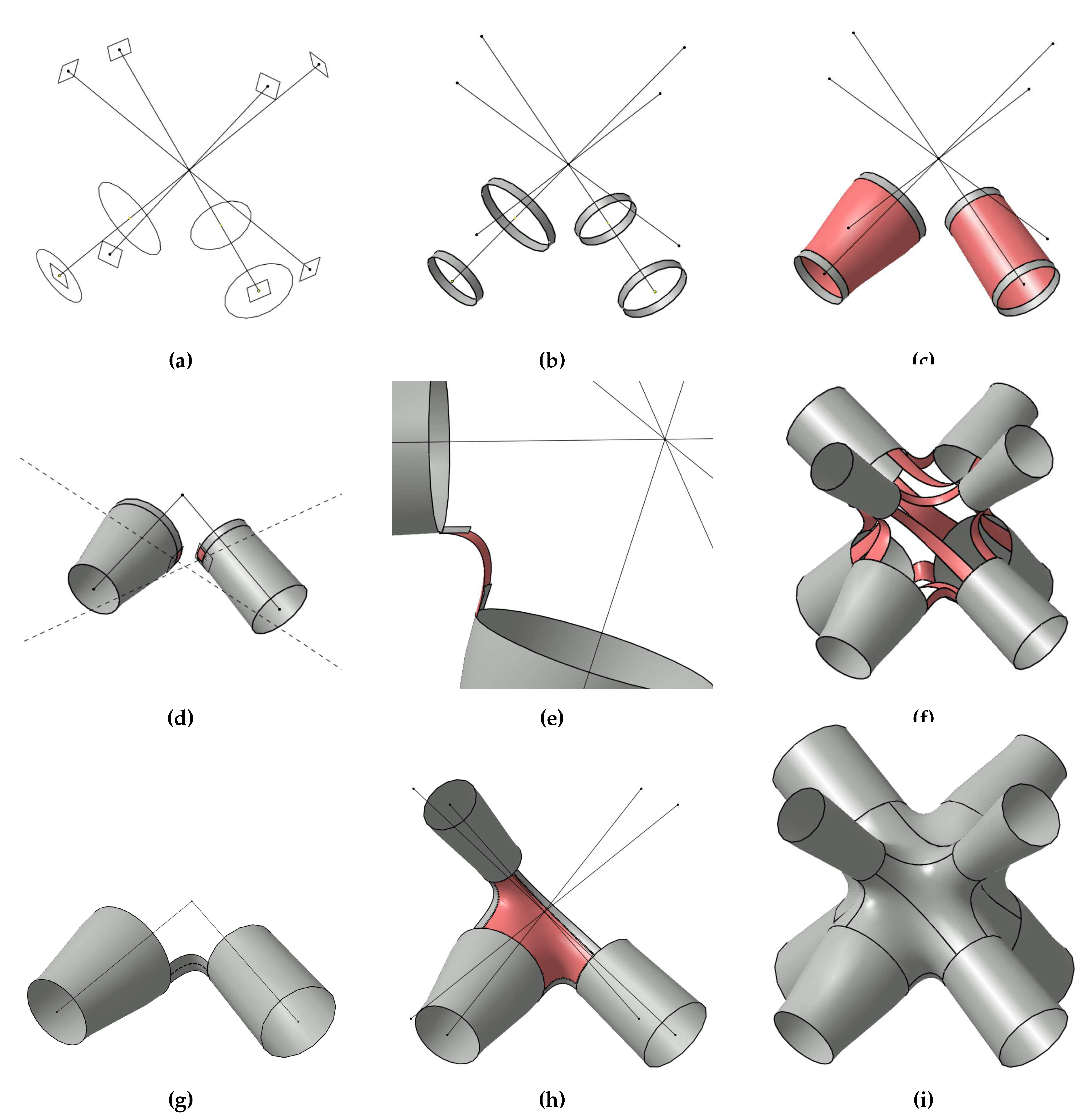
To each node of the lattice frame the construction algorithm (
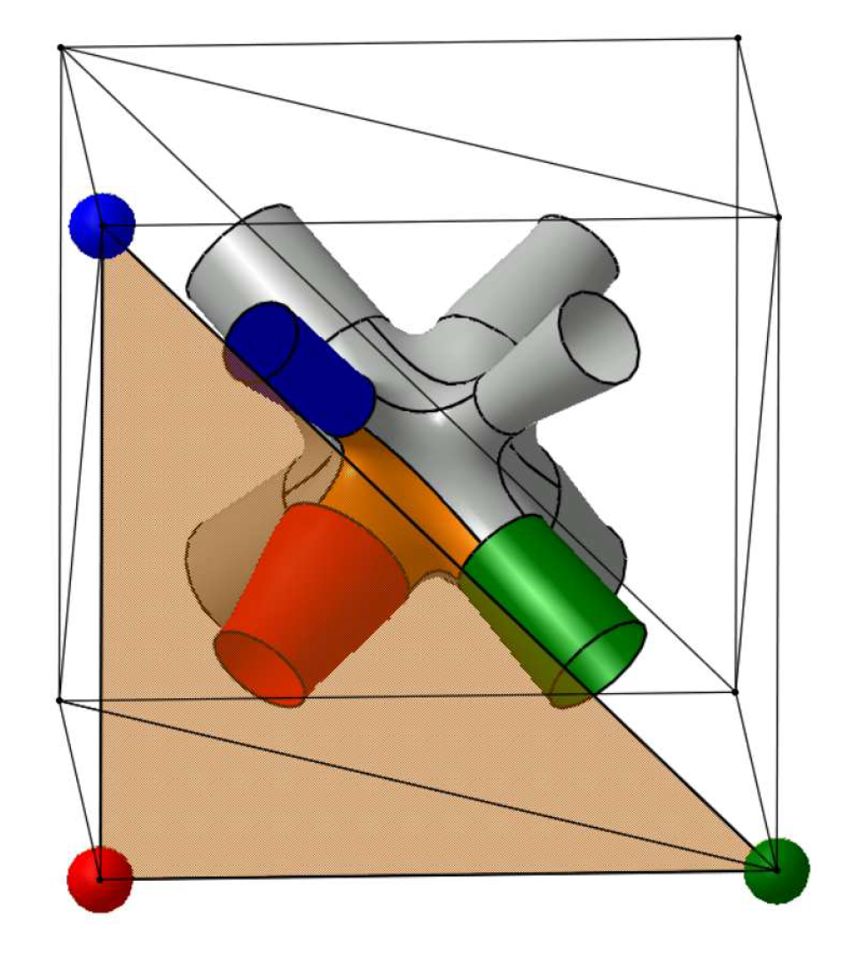
Figure 5) is applied. Its input is a subset of the original lattice frame that composes only the node itself and nodes that are connected with an edge to this node, denoted as
neighbouring nodes, as well as the desired strut radii at both ends of these edges. The construction stages are the following:
Figure 5.
Sketches of the most important stages of the general node construction step.
Figure 5.
Sketches of the most important stages of the general node construction step.
4.4. Special Case Workarounds and Continuity Fallback Mechanism
The automated computation of smooth strut transitions using the convex hull representation requires some basic properties of the lattice frame:
The neighbouring nodes of each node should not be coplanar or almost coplanar, i.e., more than three neighbouring nodes are required.
The edges converging to a node should be distributed equally in space around the node such that in every half-space exists at least one edge.
Sharp angles between edges should be avoided.
Nodes that fail to comply with these basic properties, are automatically identified by the algorithm and a special case workaround or a fall back mechanism are applied. The latter are explained in more detail in the following sections.
4.4.1. Workaround for Coplanar and Almost Coplanar Nodes
If there is a plane through the node, such that edges to all neighbouring nodes include small angles to that plane, the special case work around for coplanar and almost coplanar nodes is applied. For these node geometry, the occurrence of edges in the convex hull representation is not a suitable measure to detect struts that should be connected by a ruled surface. A more convenient measure is the corresponding edges’ polar angle. Ordered according to the value of their polar angle, neighbouring struts are connected with
-continuous ruled surfaces. Additionally, surface patches of circular disks are constructed parallel to the plane of coplanarity above and below the node. On the basis of these patches, each strut is connected by a
-continuous ruled surface. Finally, the regions between the constructed transitions and struts are filled with
-continuous 6-patches. The corresponding construction stages are sketched in
Figure 6.
4.4.2. Workaround for Nodes with Edge-Free Half-Spaces
A node is not in the interior of the convex hull of its neighbouring nodes if the edges are unequally distributed around the node in a way such that edge-free half-spaces exist. Therefore, the convex hull representation fails to identify suitable neighbouring struts. In this case, a makeshift construction point, treated as neighbouring node, is defined in the edge-free half space such that the node is in the interior of the updated convex hull (
Figure 7a). Then, the node is constructed using the general node construction step. Finally, the extra strut, pointing to the makeshift construction point, and parts of the 6-patches next to this strut are cut off in a small neighbourhood of the strut, see
Figure 7b. The resulting hole, bounded by 6-patches, is filled with a
-continuous
N-patch (
Figure 7c).
4.4.3. Geometric Continuity Fallback for Sharp Angles and Intricate Input
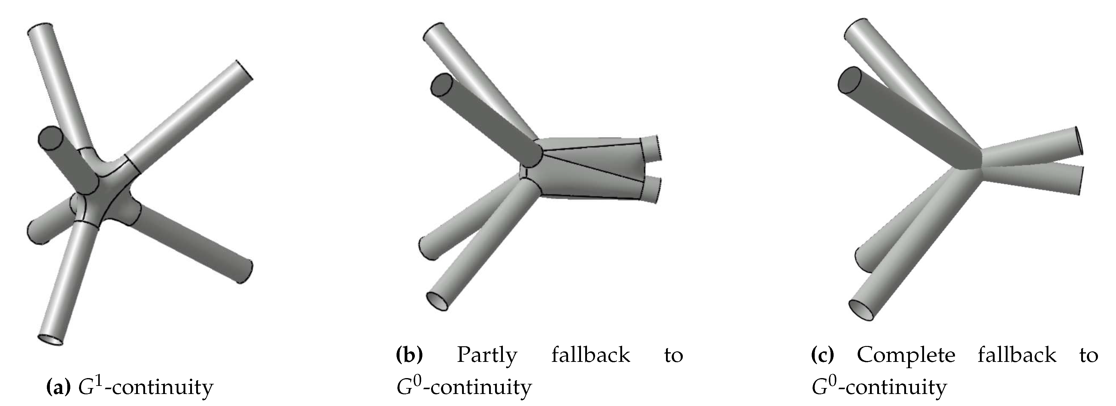
In the general node construction step, the length of struts converging to the same node is adjusted such that they are not intersecting each other. If two edges enclose a sharp angle, the corresponding struts have to be cut far from the respective node to avoid intersections. But these struts still need to be connected smoothly to other struts. As a result, the constructed smooth transitions with ruled surfaces may intersect each other. To overcome this error, the cross-boundary tangent condition in the definition of strut transitions is dropped. Ruled surfaces are used instead of
-continuous ruled surfaces (
Figure 8b). Consequently, the resulting node is partly
-continuous instead of
-continuous.
Even tough the discussed special case workarounds and fallback mechanism of the general node construction step are able to handle various node topologies, the construction of single nodes may still fail or may be even impossible due to intricate input, e.g., regarding the relation of strut radii and length and resulting self intersections. In order to not interrupt the construction algorithm in this case, a complete fallback mechanism to
-continuity is integrated (
Figure 8c). A ruled surface is constructed for each edge converging to the node and they are joined by boolean operations. Due to the parallelized approach, the construction of the respective node can be repeated independently of the other nodes in the lattice frame in a post processing step if
-continuity is required in each node. The repetition can be conducted for example with more sensitive special case recognition parameters or adjusted radii inputs.
5. Demonstration, Application and Discussion
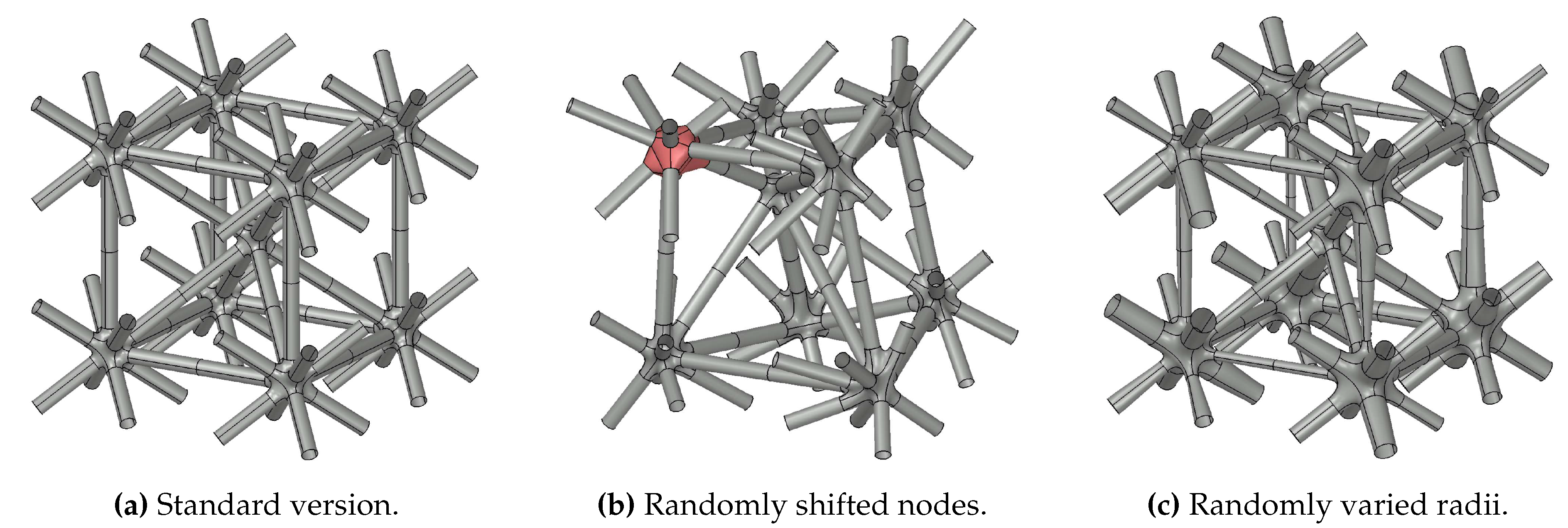
The developed algorithm is demonstrated on the elementary cell of a body centric cubic lattice structure in three different versions (
Figure 9). First, the elementary cell is constructed with constant strut radii and periodic node distribution (
Figure 9a). Then, the construction is repeated but with randomly shifted nodes (
Figure 9b) and with randomly varied strut radii (
Figure 9c).
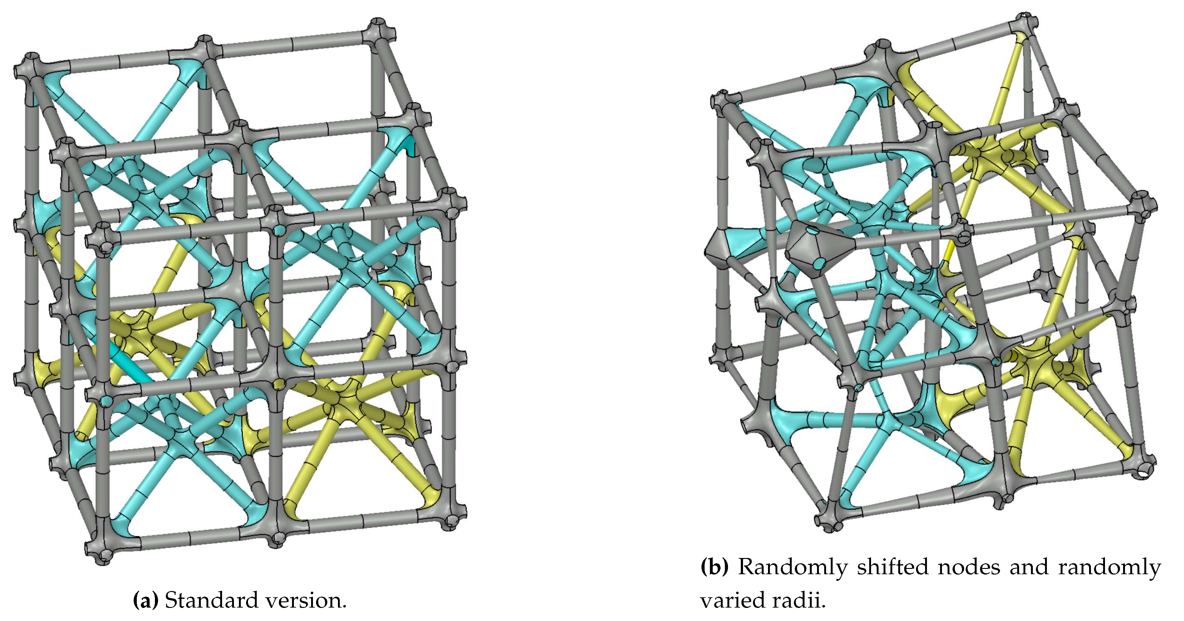
In
Figure 10, a lattice structure composed of eight elementary cells with different unit cell topologies is shown in two versions. First, only the topology is varied (
Figure 10a). Then, strut radii and node positions are varied additionally (
Figure 10b).
It is seen in these examples that the proposed method is able to construct unit-cell based lattice structures as well as such with irregular topologies. Furthermore, radii gradients between the ends of a single strut and between struts converging to the same node can be realized and parametrized exactly. As a result, the proposed method is in particular suitable for lightweight design constructions of irregular shaped and radius gradient containing lattice structures derived form topology optimization results.
Nevertheless, it is not always possible to construct a smooth node. Just as the lattice construction methods in [
13,
14], the proposed general node construction step shows difficulties with sharp and wide angles between struts because the convex hull-based smooth transition design is not practicable. To overcome this issue, different special case workarounds and a fallback mechanism in geometric continuity are integrated in the algorithm. Among the nodes shown in
Figure 9, there is one node in the top left corner of
Figure 9b, to that the automatic fallback mechanism in geometric continuity is applied. All the other nodes are constructable with the general node construction step. Also in the lattice shown in
Figure 10b the fallback is used twice. However, due to the subdivision of the lattice construction task in node-wise steps the nodes that are constructed using the fallback mechanism remain accessible for post processing and their construction can be repeated with different parameters without affecting other parts of the lattice structure.
Furthermore, another advantage of the node-wise subdivision of the construction task is the resulting parallelizability. Therefore, the speed can be increased by orders of magnitude, which is crucial to handle large-scale lattice structures and to integrate it in existing construction software. Requiring besides basic geometric operations only the three different patch construction methods described in
Section 3 for the generation of surface patches, the developed algorithm can be integrated in any standard CAD software that supports the latter.
The construction time of the 35-node lattice in
Figure 10b was recorded. It took five minutes and eight seconds to construct the whole lattice structure even without using the parallelization on a standard desktop PC. This corresponds to a construction time of 8,8 seconds per node. Compared to the construction time of approximately one hour per node using the manual scheme in [
17], the developed method in this paper is distinctly faster.
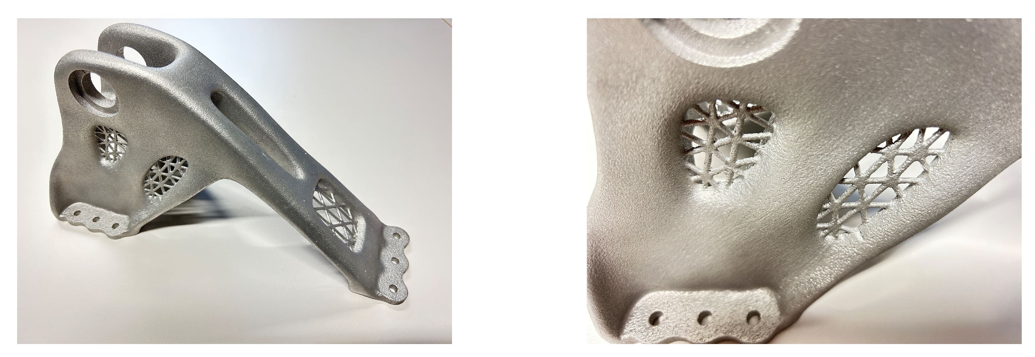
The lattice construction algorithm was applied to construct lattice infills for an aircraft component [
8]. Pictures of the additively manufactured component, corresponding to one of the designs are shown in
Figure 11. Constructing the lattice infill using surface patches facilitated the construction of smooth interfaces between the infill and the surrounding geometry. In
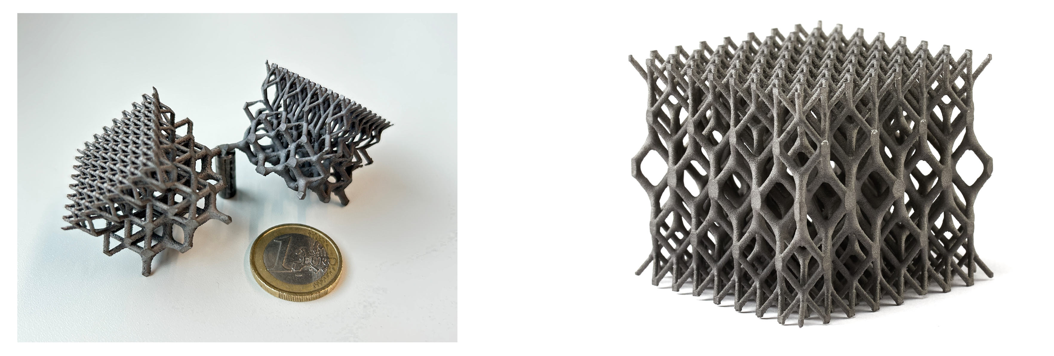
Figure 12, printed lattice cell cubes with topological and radii gradients are depicted.
6. Conclusions
In this work, an automated surface patch-based algorithm is proposed that can smoothly solidify lattice frames with a large variety of topologies. At the same time local shape parameters, such as strut radii, are exactly and individually modifiable. For specific strut configurations, such as coplanar nodes or nodes with edge-free half spaces, workarounds were developed to guarantee the constructability, when the convex hull-based transition construction is not applicable. In any case, a fallback mechanism in geometric continuity catches nodes that are not smoothly constructable by the algorithm. Especially dense lattice structures with high radius to length ratios of their edges can be a limitation to the method.
The proposed algorithm is suitable for wireframe solidifications in engineering contexts due to its flexibility in topology, parallelizability, parametrizability and integrability in CAD software.
Having an algorithm that is able to automatically construct lattice structures given topology and strut radii as input parameters, it can be used to automatize the construction of lattice infills. Further research could focus on the optimization of the wireframe topology and shape parameters for different applications and load cases and on the robustness of the method regarding dense lattice structures.
References
- Tang, Y.; Dong, G.; Zhao, Y.F. A hybrid geometric modeling method for lattice structures fabricated by additive manufacturing. Int. J. Adv. Manuf. Technol. 2019, 102, 4011–4030. [Google Scholar] [CrossRef]
- Nazir, A.; Abate, K.M.; Kumar, A.; Jeng, J.Y. A state-of-the-art review on types, design, optimization, and additive manufacturing of cellular structures. Int. J. Adv. Manuf. Technol. 2019, 104, 3489–3510. [Google Scholar] [CrossRef]
- Feng, J.; Fu, J.; Lin, Z.; Shang, C.; Li, B. A review of the design methods of complex topology structures for 3D printing. Vis. Comput. Ind. Biomed. Art 2018, 1, 5. [Google Scholar] [CrossRef] [PubMed]
- Mahmoud, D.; Elbestawi, M.A. Lattice Structures and Functionally Graded Materials Applications in Additive Manufacturing of Orthopedic Implants: A Review. J. Manuf. Mater. Process. 2017, 1. [Google Scholar] [CrossRef]
- Shinde, M.; Ramirez-Chavez, I.E.; Anderson, D.; Fait, J.; Jarrett, M.; Bhate, D. Towards an Ideal Energy Absorber: Relating Failure Mechanisms and Energy Absorption Metrics in Additively Manufactured AlSi10Mg Cellular Structures under Quasistatic Compression. J. Manuf. Mater. Process. 2022, 6. [Google Scholar] [CrossRef]
- Vaissier, B.; Pernot, J.P.; Chougrani, L.; Véron, P. Parametric design of graded truss lattice structures for enhanced thermal dissipation. Comput. Aided Des. 2019, 115, 1–12. [Google Scholar] [CrossRef]
- Boschetto, A.; Bottini, L.; Macera, L.; Vatanparast, S. Additive Manufacturing for Lightweighting Satellite Platform. Appl. Sci. 2023, 13. [Google Scholar] [CrossRef]
- Hoschke, K.; Pfaff, A.; Fleig, L.; Bierdel, M.; Jäcklein, M.; Riedel, W.; Hiermaier, S. A Parametric Mesostructure Approach for Robust Design of Additive Manufacturing Parts. Fraunhofer Direct Digital Manufacturing Conference (DDMC), 2018.
- Ramsaier, M.; Till, M.; Schumacher, A.; Rudolph, S. On a Physics-based Reconstruction Algorithm for Generating Clean Parametric Native CAD-Models from Density-based Topology Optimization Results. The World Congress of Structural and Multidisciplinary Optimization, 2019.
- Maskery, I.; Aremu, A.; Parry, L.; Wildman, R.; Tuck, C.; Ashcroft, I. Effective design and simulation of surface-based lattice structures featuring volume fraction and cell type grading. Mater. Des. 2018, 155, 220–232. [Google Scholar] [CrossRef]
- Savio, G.; Meneghello, R.; Concheri, G. Geometric modeling of lattice structures for additive manufacturing. Rapid Prototyp. J. 2018, 24, 351–360. [Google Scholar] [CrossRef]
- Goel, A.; Anand, S. Design of Functionally Graded Lattice Structures using B-splines for Additive Manufacturing. Procedia Manuf. 2019, 34. [Google Scholar] [CrossRef]
- Mattingly, W.A.; Chariker, J.H.; Paris, R.; Chang, D.j.; Pani, J.R. 3D modeling of branching structures for anatomical instruction. J. Vis. Lang. Comput. 2015, 29. [Google Scholar] [CrossRef] [PubMed]
- Srinivasan, V.; Mandal, E.; Akleman, E. Solidifying Wireframes. Proceedings of the 2004 bridges conference on mathematical connections in art, music, and science, 2005.
- Al-Ketan, O.; Lee, D.W.; Rowshan, R.; Abu Al-Rub, R.K. Functionally graded and multi-morphology sheet TPMS lattices: Design, manufacturing, and mechanical properties. J. Mech. Behav. Biomed. Mater. 2020, 102, 103520. [Google Scholar] [CrossRef]
- Hu, C.; Lin, H. Heterogeneous porous scaffold generation using trivariate B-spline solids and triply periodic minimal surfaces. Graph. Model. 2021, 115, 101105. [Google Scholar] [CrossRef]
- Hassani, V.; Khabazi, Z.; Raspall, F.; Banon, C.; Rosen, D. Form-Finding and Structural Shape Optimization of the Metal 3DPrinted Multi-Branch Node with Complex Geometry. Comput. Aided Des. Appl. 2019, 17, 205–225. [Google Scholar] [CrossRef]
- Campbell, R.J.; Flynn, P.J. A survey of free-form object representation and recognition techniques. Comput. Vis. Image. Underst. 2001, 81, 166–210. [Google Scholar] [CrossRef]
- Gallier, J. Geometric Methods and Applications: For Computer Science and Engineering; Springer Science & Business Media, 2001; Vol. 38. [Google Scholar]
- Farin, G. Curves and surfaces for CAGD: A practical guide; Morgan Kaufmann, 2002. [Google Scholar]
- Schaaf, J.; Ravani, B. Geometric continuity of ruled surfaces. Comput. Aided Geom. Des. 1998, 15, 289–310. [Google Scholar] [CrossRef]
- Gregory, J.A.; Zhou, J. Filling polygonal holes with bicubic patches. Comput. Aided Geom. Des. 1994, 11, 391–410. [Google Scholar] [CrossRef]
- Chui, C.K.; Lai, M.J. Filling polygonal holes using C1 cubic triangular spline patches. Comput. Aided Geom. Des. 2000, 17, 297–307. [Google Scholar] [CrossRef]
- Piegl, L.A.; Tiller, W. Filling n-sided regions with NURBS patches. Vis. Comput. 1999, 15, 77–89. [Google Scholar] [CrossRef]
|
Disclaimer/Publisher’s Note: The statements, opinions and data contained in all publications are solely those of the individual author(s) and contributor(s) and not of MDPI and/or the editor(s). MDPI and/or the editor(s) disclaim responsibility for any injury to people or property resulting from any ideas, methods, instructions or products referred to in the content. |
© 2023 by the authors. Licensee MDPI, Basel, Switzerland. This article is an open access article distributed under the terms and conditions of the Creative Commons Attribution (CC BY) license (http://creativecommons.org/licenses/by/4.0/).
