1. Introduction
Convolutional Neural Networks (CNNs) have demonstrated remarkable performance in various domains, including image classification, object detection, and speech recognition [
1,
2]. However, effectively integrating CNNs into embedded systems with limited power and size requirements remains a significant challenge. This is primarily due to the high computational demands of CNNs, which can be resource-intensive for embedded systems. Typically, embedded systems revolve around general-purpose central processing units (CPUs) capable of handling a wide range of tasks. However, CPUs have limitations when it comes to implementing CNNs, mainly because of the repetitive and computationally intensive nature of large-scale convolution operations. To address this challenge and efficiently implement CNNs, dedicated hardware accelerators such as graphic processing units (GPUs) or field-programmable gate arrays (FPGAs) are commonly employed [
3]. Among these options, FPGAs have gained popularity for implementing CNNs in embedded systems, primarily due to their ability to perform convolution operations in parallel with high-energy efficiency. Compared to GPUs, FPGAs offer higher energy efficiency, making them an attractive choice for resource-constrained embedded systems [
4,
5,
6].
The generation of feature maps, achieved through the fundamental convolution operation using multiple kernels, plays a crucial role in CNNs. To minimize computational costs and simplify the model, reducing the size of these feature maps is necessary. The max-pooling technique is employed to achieve this while preserving spatial invariance of distinct features within the feature maps [
7,
8]. Typically, a window of size 2×2 is used in max-pooling operation, ensuring spatial overlap of the maximum values, and sampling values along the horizontal and vertical axes every 2 positions [
8]. As a result, the feature map’s width and height can be reduced by half, resulting in a 4x reduction in size while preserving the maximum values that represent the distinct features of the feature map. In recent years, there has been a growing focus on improving object detection performance by utilizing feature maps of various resolutions. This approach often involves incorporating max-pooling techniques with larger and diverse window sizes [
9]. For instance, YOLOv4's Spatial Pyramid Pooling (SPP) employed the max-pooling with window sizes of 5, 9, and 13 [
9,
10,
11]. By employing different window sizes, the pooling operation captures multi-scale information from the feature maps, enabling the model to detect objects at different sizes and scales more effectively. This approach improves object detection accuracy and robustness in complex scenes [
9,
10,
11].
The 2x2 max-pooling operation was simply implemented by using two delay buffers and three comparators on FPGAs [
12,
13]. This 2×2 max-pooling engine was then extended to accommodate the max-pooling with the
k×
k window by utilizing
k delay buffers and
k×
k-1 comparators [
14,
15]. However, despite its simplicity, the
k×
k-1 comparator-based max-pooling engine is inefficient in terms of hardware utilization due to the requirement of numerous comparators with large windows. Additionally, it results in high power consumption due to the usage of many logic cells. In order to reduce the required comparators, we propose two efficient max-pooling engines named the rank tracking based max-pooling (RTB-MAXP) engine and the cascaded maximum based max-pooling (CMB-MAXP) engine. The two-dimensional max-pooling operation is decomposed into the horizontal max-pooling operation and the vertical max-pooling operation for the operational efficiency. Thus, the two-dimensional max-pooling operation can be accomplished with the two-step one-dimensional max-pooling operation, which leads to the reduction of comparison operations from
k×
k-1 to 2
k-2. In the RTB-MAXP engine, the max-pooling operation is accomplished by tracking the ranks of the values within the scalable window and extracting the top ranked value as the maximum value. On the other hand, the CMB-MAXP engine employs the cascaded maximum operations to find the maximum value within the window.
This paper is organized as follows: In section 2, the two-dimensional max-pooling operation is represented into the form of two-stage max-pooling operations, and then the architecture of the RTB-MAXP engine is introduced in
Section 3.
Section 4 describes the architecture of the proposed CMB-MAXP engine.
Section 5 shows the implementation results of the RTB-MAXP engine and CMB-MAXP engine and then those are compared in terms of resource utilization. Finally, the conclusion is provided in
Section 6.
2. Max-Pooling Operation
The max-pooling is a fundamental operation in deep learning used for reducing the spatial dimensions of a feature map. It involves sliding a window over the feature map and selecting the maximum value within the window [
5]. Since the values in the feature map represent features, it is crucial to avoid losing important large values when reducing the size of the feature map. The max-pooling ensures that the maximum values within the window are duplicated and remained, preventing the loss of maximum values during spatial sampling. Given an input feature map
x, containing three-dimensional data of
P channels, width
W, and height
H, the output of the max-pooling operation
z can be expressed as the following equation:
where
p (0≤
p≤
P-1) represents the index of the channel,
i and
j (0≤
i≤
H-1, 0≤
j≤
W-1) denote the vertical and horizontal indices of the feature map, the operator "max" represents the maximum operation, and the operator
represents a floor operation, respectively. The value of
k determines the size of the
k×
k square window. Note that the subsampling reducing the spatial size of feature maps
z is not considered in this paper because it can easily and simply be implemented.
The two-dimensional max-pooling operation in (1) can be decomposed into two distinct one-dimensional max-pooling operations as follows:
Operations in (2) and (3) can be named as the horizontal axis max-pooling operation and the vertical axis max-pooling operation, respectively. The output of the horizontal max-pooling operation is fed to the input of the vertical max-pooling operation. Using these two sequential max-pooling operations reduces the number of the comparison operations compared to the two-dimensional max-pooling operation in (1), i.e. from k×k-1 to 2k -2.
3. Rank Tracking Based Max-Pooling (RTB-MAXP) Engine
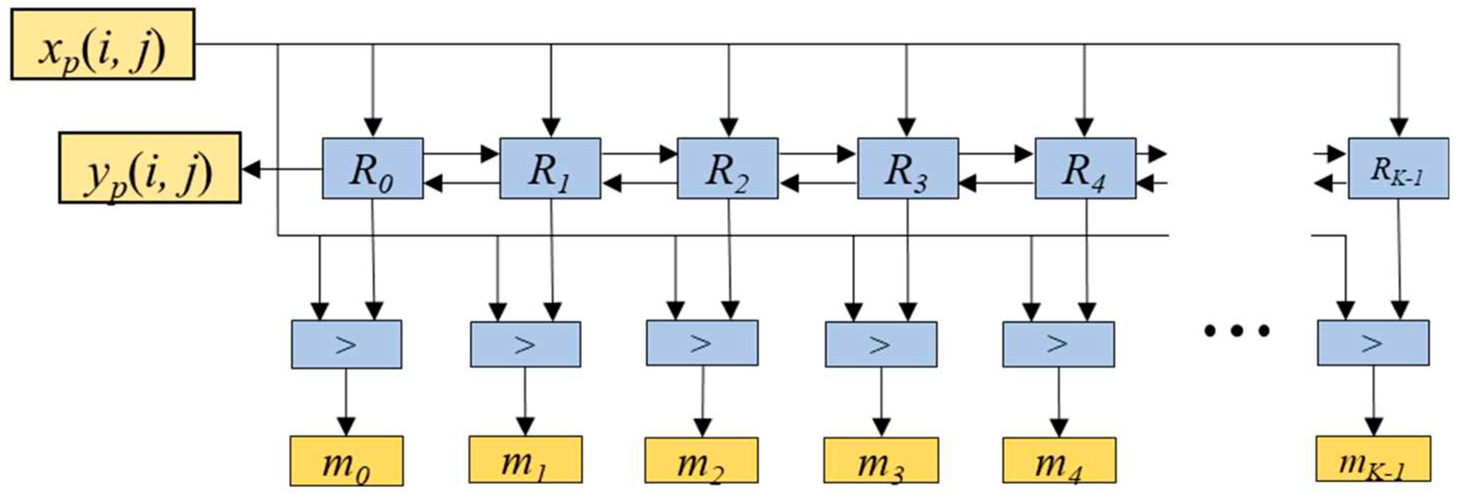
In this section, a two-step max-pooling operation engine, named RTB-MAXP engine, is introduced. This engine is designed on the basis of the rank tracking concept to find the maximum value within a kernel window as shown in
Figure 1. It has registers that store the sample values within a window in descending order. The maximum value is stored in register
r0, and the values within the window are stored in descending order down to
rK-1, where
K is the maximum window size. When a new value of the feature map is input to the engine, the registers need to be updated. For example, if the new input value
xp(
i,
j) is smaller than
r0 but larger than
r1, the value in
r3 is the value pushed out of the window, the value of
r2 is shifted to
r3, the value of
r1 is shifted to
r2, and the value
xp(
i,
j) is stored in
r1 simultaneously. Meanwhile the values of
r0 and
r4,... ,
rK-1 remain unchanged. The resulting output of this one-dimensional max-pooling engine corresponds to the value stored in
r0. This rank tracking concept is implemented through two distinct blocks: the rank-counting block and the delay-counting block.
The rank-counting block is for storing the input values into a corresponding register based on their ranks. It is comprised of
K blocks named
Rv (
v=0, 1, ...,
K-1) and the comparator blocks denoted as ‘>’, as shown in
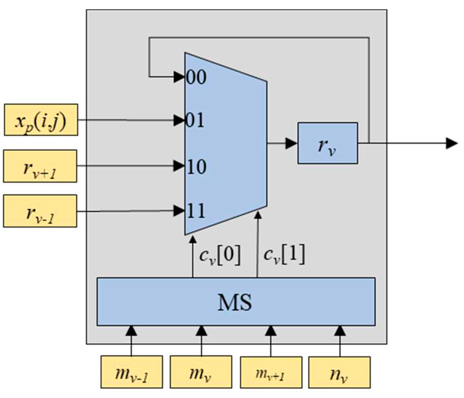
Figure 2. Each
Rv block is composed of a multiplexer, a multiplexer switch (MS), and a register
rv as depicted in
Figure 3. The inputs for the multiplexer include the input feature map value
xp(
i,
j), the value of
rv, the value of
rv-1 (one step larger value than
rv), and the value of
rv+1 (one step smaller than
rv). The multiplexer selects one out of these inputs based on the MS’s output values
cv[0] and
cv[1].
Table 1 shows the relationship between input values of
mv-1,
mv,
mv+1, and
nv, and the corresponding output values
cv[0] and
cv[1]. The values of
mv-1,
mv, and
mv+1 are obtained from the outputs of the comparators shown in
Figure 2, while the value of
nv is obtained from the delay-counting block. The comparator block outputs ‘1’ when
xp(
i,
j) is larger than
rv, and ‘0’ otherwise.
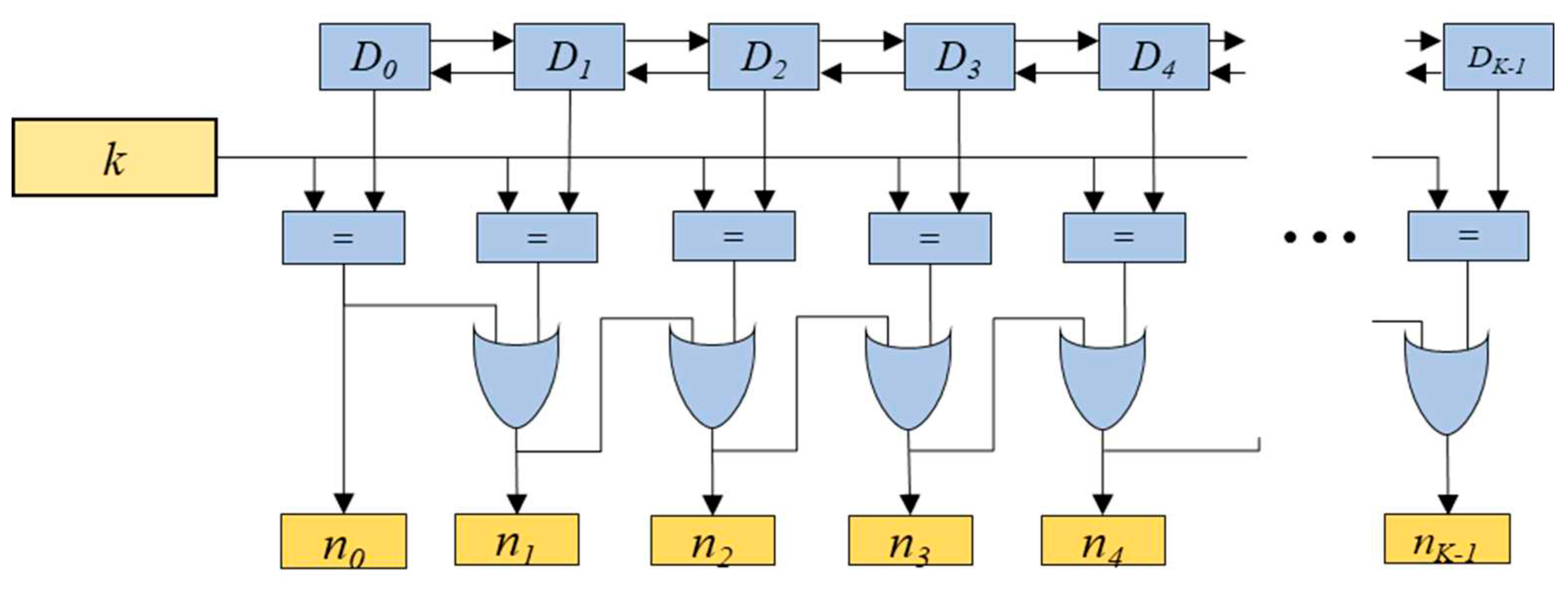
The value pushed out of the window is also required to be tracked for the max-pooling operation, for which the delay-counting block is employed. The delay-counting block indicates the value
nv (
v=0, 1,…,
K-1) which is pushed out of the window. It consists of the
K blocks named
Dv (
v=0, 1, ...,
K-1), the comparator blocks denoted as ‘=’, and OR gates, as depicted in
Figure 4. The block
Dv outputs the delay indicating value corresponding to the ranking-counting value
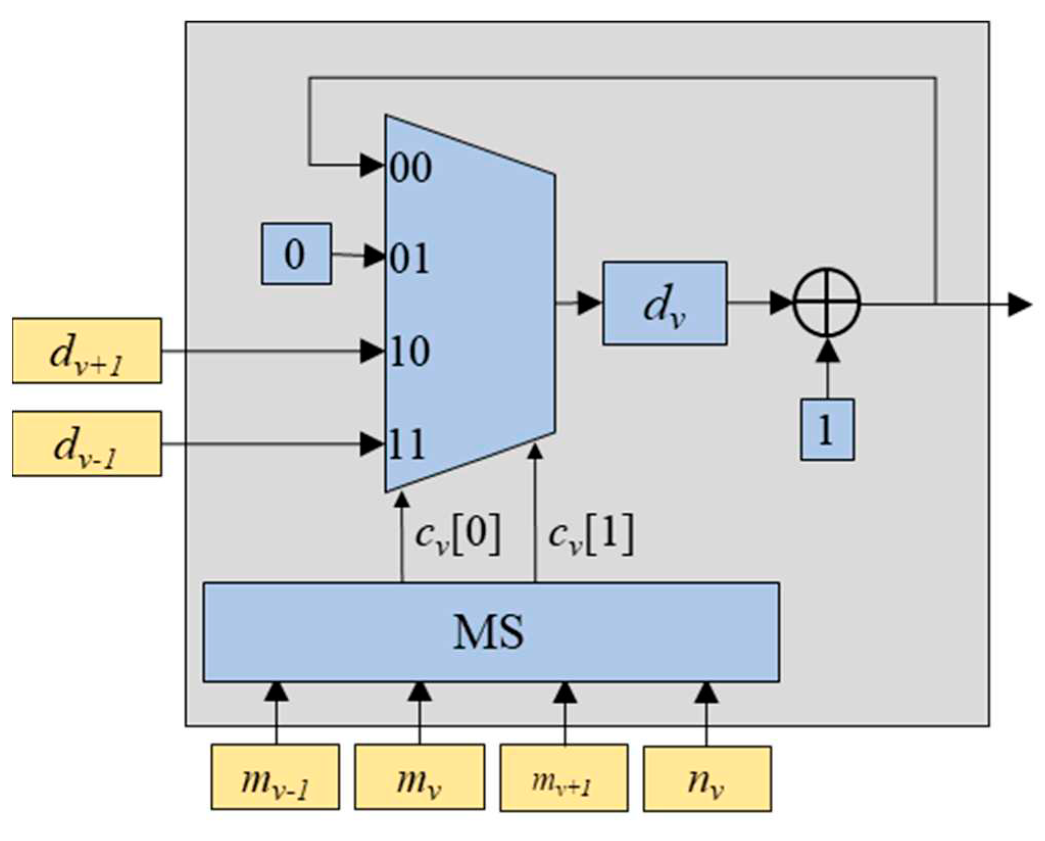
rv. Similar to the ranking-counting block, the block
Dv is composed of a multiplexer, a MS, and a register denoted as ‘
dv’, as shown in
Figure 5. The inputs for the multiplexer include the increased delay-counting value
dv+1 corresponding to
rv, the delay-counting value 0 corresponding to
xp(
i,
j), the increased delay-counting value
dv-1+1 corresponding to
rv-1, the increased delay-counting value
dv+1+1 corresponding to
rv+1. The multiplexer selects one out of these inputs based on the MS’s output values
cv[0] and
cv[1]. Note that the MS is the same as that in block
Rv. As shown in
Figure 4, the comparator block outputs 1 if the delay-counting value is equal to the selected window size
k, and 0 otherwise. This makes it possible to determine which value is pushed out of the window. The value
nv is the output of the OR operation between
nv-1 and the output of the comparator block as shown in
Figure 4.
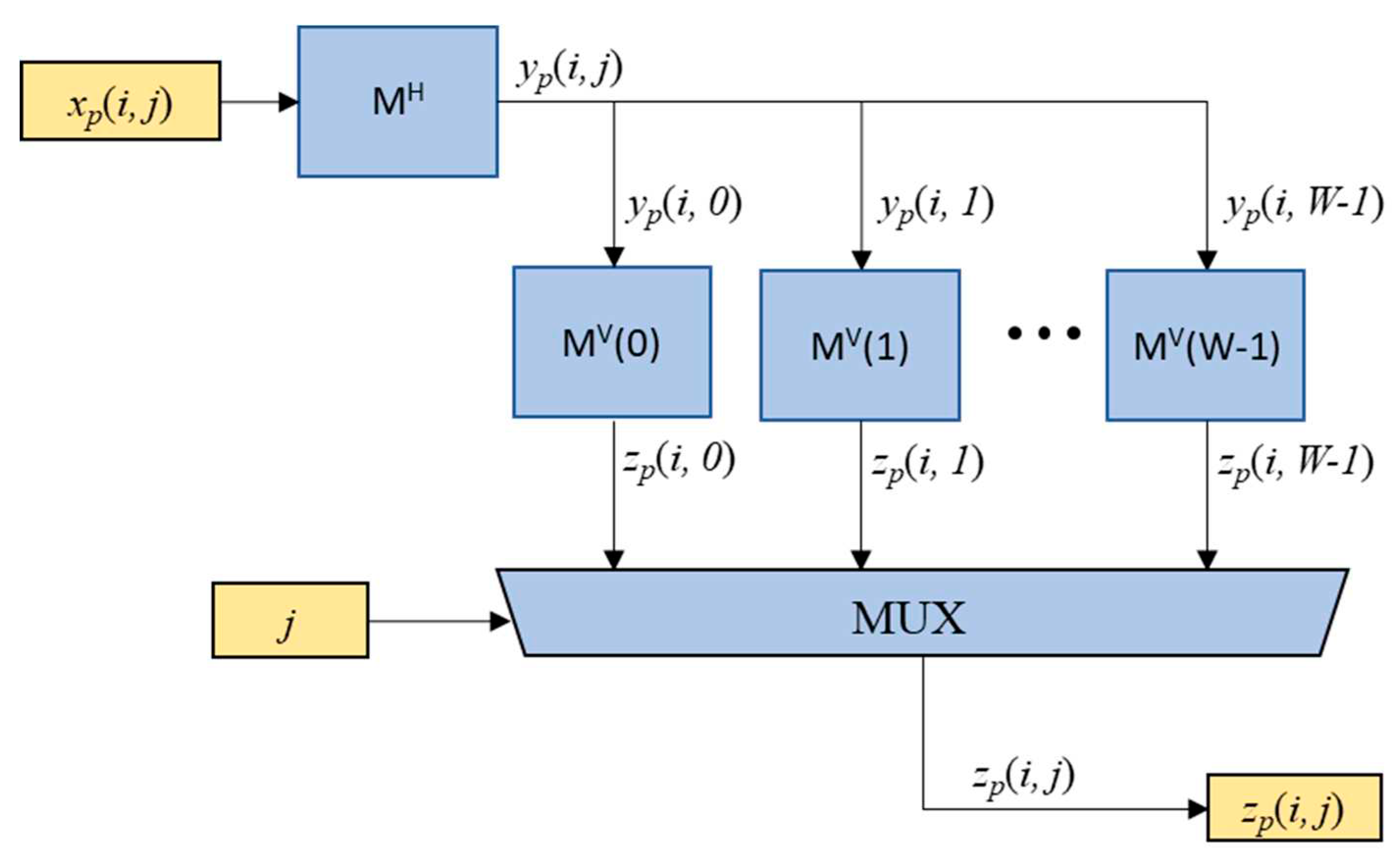
The two-dimensional max-pooling engine is implemented by employing the multiple one-dimensional rank tracking based max-pooling engines as depicted in
Figure 6. The block marked with “M
H” represents the horizontal one-dimensional max-pooling engine shown in equation (2). Specifically,
yp(
i,
j) is obtained from the highest-ranking value
r0 of the ranking-counting block illustrated in
Figure 2. In order to obtain
zp(
i,j), where 0≤
j≤
W-1, each column of
yp(
i,
j) is then fed into
W vertical max-pooling engines
MV(
j). Then, the final output
zp(
i,j) is obtained from the multiplexer (MUX) based on the value of horizontal index
j.
The proposed max-pooling engine can be efficiently implemented by sharing the common components. Firstly, the MS in the Rv block and the Dv block for each v can be shared. Since the output values cv[0] and cv[1] of these two MSs are identical, they can be used commonly for a one-dimensional max-pooling engine. Secondly, since every vertical max-pooling engine MV(j) operates at non-overlapped timing for sequentially incoming yp(i,j) values, all components of MV(j) for 0≤j≤W-1 can be shared, except for registers used to store ranking-counting values and delay counting values.
4. Cascaded Maximum Based Max-Pooling (CMB-MAXP) Engine
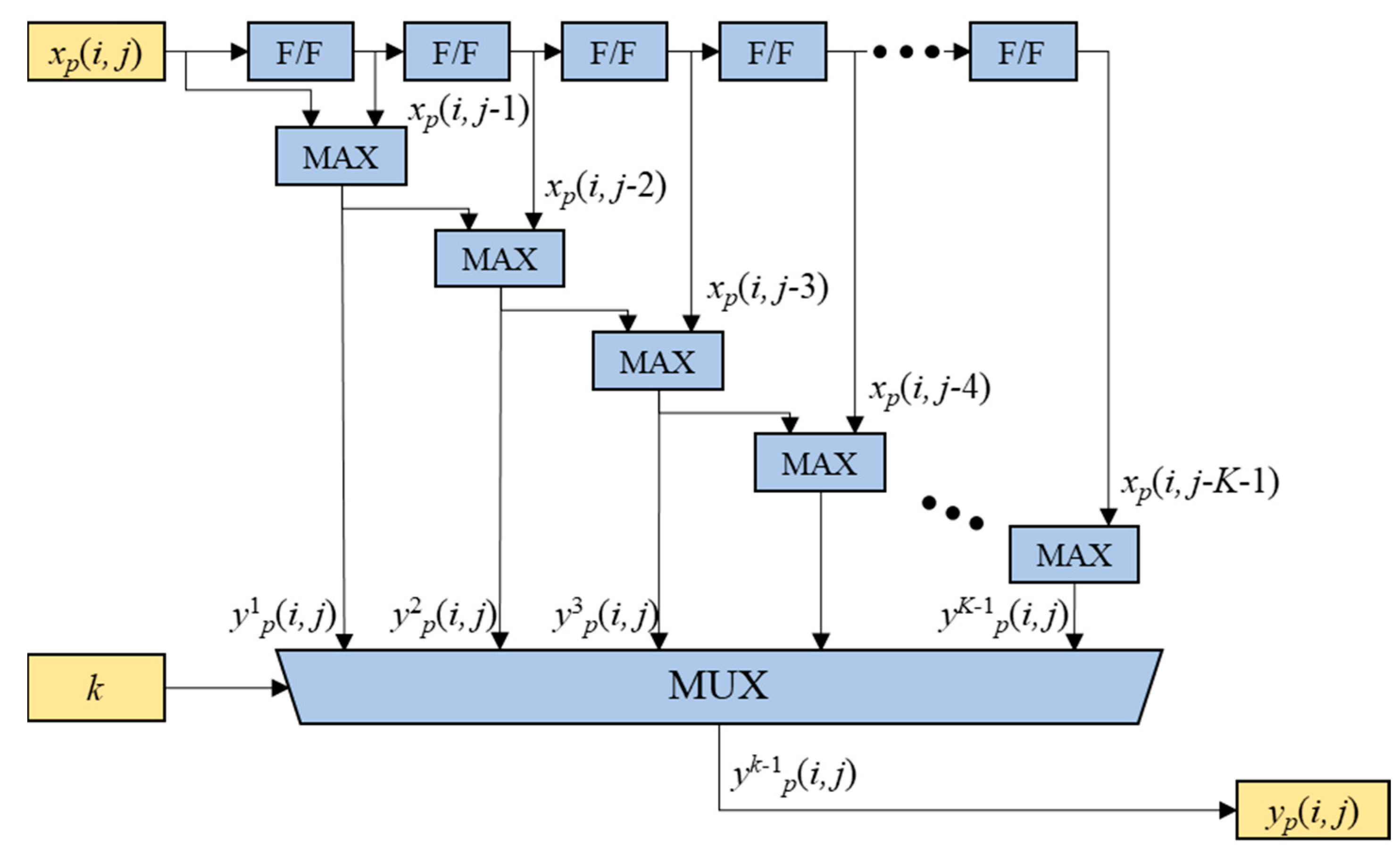
In this section, another two-step max-pooling operation engine, named CMB-MAXP engine, is presented. In the CMB-MAXP engine, the horizontal axis max-pooling operation of (2) is accomplished through the cascaded maximum operations as illustrated in
Figure 7. The cascaded F/Fs and maximum operators find the maximum values
ywp(
i,
j) for 1≤
w≤
K-1 of the input sequence elements
xp(
i,
j),
xp(
i,
j-1),
xp(
i,
j-2), …, and
xp(
i,
j-
w). The cascaded maximum operation can be expressed in a recursive form, as shown in (4).
The yk-1p(i, j) is chosen as the output sequence elements yp(i, j) of the horizontal axis max-pooling operation by a MUX according to the scalable kernel size parameter k, i.e. .
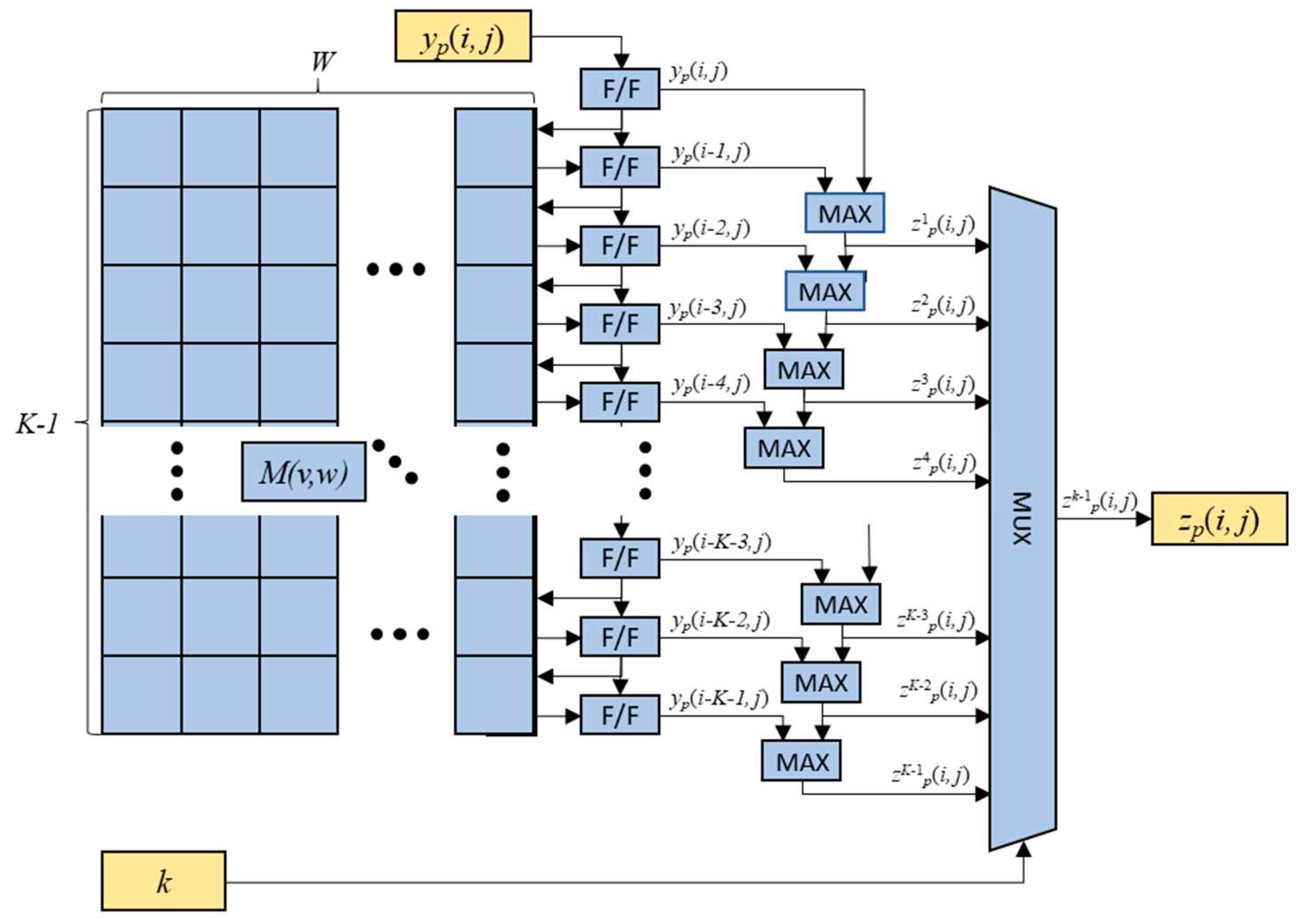
The structure of the vertical axis max-pooling operation is shown in
Figure 8, and is almost identical to that of the horizontal axis max-pooling engine except for the additional usage of the two-dimensional memory elements
M(
v,
w) for 0≤
v≤
K-1 and 0≤
w≤
W-1. The memory elements are employed for restoring the previous row’s values of the feature map
yp(
i-1,
j),
yp(
i-2,
j), …,
yp(
i-
K-1,
j) for the vertical max-pooling operations. The previously loaded elements
yp(
i-1,
j),
yp(
i-2,
j), …,
yp(
i-
K-1,
j) are fed into F/Fs from the memory element
Mp(0,
j),
Mp(1,
j), …,
Mp (
K-1,
j), and the new delayed element
yp(
i,
j),
yp(
i-1,
j),…,
yp(
i-
K-2,
j) are recursively fed into the corresponding memory elements. The maximum values
zwp(
i,
j) of the elements
yp(
i,
j),
yp(
i-1,
j),
yp(
i-2,
j), …,
yp(
i-
w,
j) are obtained by comparators and the final output sequence element
zp(
i,
j) is obtained from the MUX according to the value of
k.
5. Implementations
The proposed RTB-MAXP engine and CMB-MAXP engine were implemented for being employed in an FPGA-based CNN accelerator. The target model of the CNN was YOLOv4-CSP-S-Leaky which was developed for the object detection [
9]. It consists of 108 layers including the 3x3 convolution layers, the 1x1 convolution layers, the residual addition layers, the concatenation layers, the max-pooling layers, and the up-sampling layers. The max-pooling layers are utilized for the SPP operation. When the input feature map size of the model is 256x256, the input feature map size of the max-pooling operations is 32x32 and the window sizes are 5, 9, and 13. Thus, the possible maximum window size
K was chosen as 13 and the possible maximum width of the feature map
W was set as 32 for the proposed max-pooling engines.
The max-pooling engines were designed using VHSIC Hardware Description Language (VHDL) and their behaviors were verified by simulations using the ModelSim which is the Mentor Graphics’ simulation and debugging tool for digital logics.
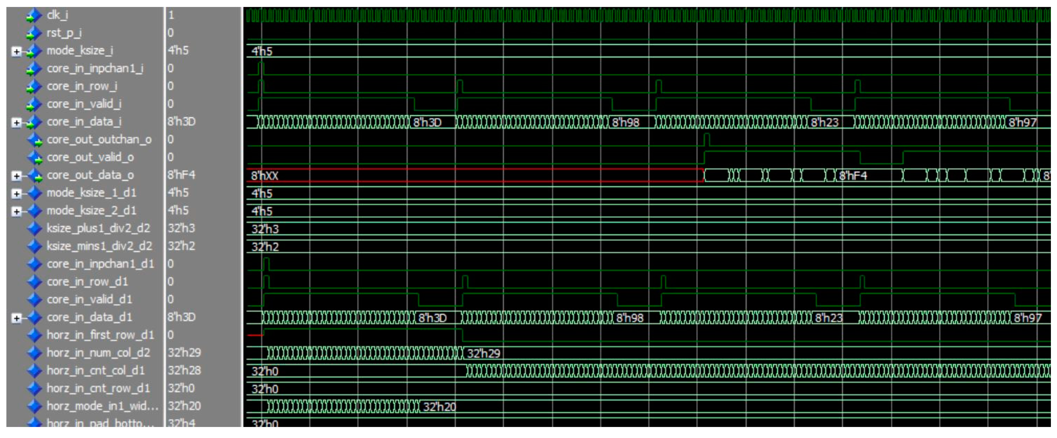
Figure 9 and
Figure 10 are the simulation results for the RTB-MAXP engine and the CMB-MAXP engine, respectively. The parameters
k and
W were named as ksize_i, width_i, and set to 5 and 0x20(=32). Note that prefixes of the signal are included in the signal of the figure. The signals inpchan_i, row_i, and valid_i were used for data synchronization with a start point of a new input channel, a start point of a new row, a valid point of data, respectively. The signal data_i indicates the data of a feature map aligned with the data synchronization signals. The output data signal data_o of the max-pooling engines comes out along with the data synchronization signals, i.e., outchan_o, valid_o.
In order to accelerate the max-pooling operations for the CNN, either the 16 RTB-MAX engines or the 16 CMB-MAXP engines were used to process 16 feature maps (0≤
p≤15) in parallel. These 16 max-pooling engines can increase the processing speed by 16 times in sacrifice of the FPGA resource. The designed two max-pooling engines were synthesized, placed, and routed in Xilinx Vivado Design Suite for the Xilinx VCU118 evaluation platform. The platform includes the Xilinx Vertex UltraScale+ FPGA XCVU9P.
Table 2 shows the resource utilization of the RTB-MAXP engine and CMB-MAXP engine with
K=13 and
W=32 as a result of the implementation for the targeted FPGA. The RTB-MAXP engine required 157,515 LUTs and 99,342 FFs, that is, 13.4% and 4.2% of the total available resources, respectively. On the other hand, the CMB-MAXP engine required 28,765 LUTs, 2,688 LUTRAMs, and 76,906 FFs, that is, 2.43%, 0.45%, and 3.25%, respectively. The CMB-MAXP engine needs much fewer LUTs than the RTM-MAXP engine, but additionally requires few LUTRAMs. It is because of the buffer for the previous row data. The LUTs were used for this buffer in the RTM-MAXP engine while the LUTRAMs were used for that in the CMB-MAXP engine.
The proposed RTB-MAX engine and CMB-MAXP engines were imported in our CNN accelerator. The CNN accelerator was tested on the target VCU118 evaluation platform board.
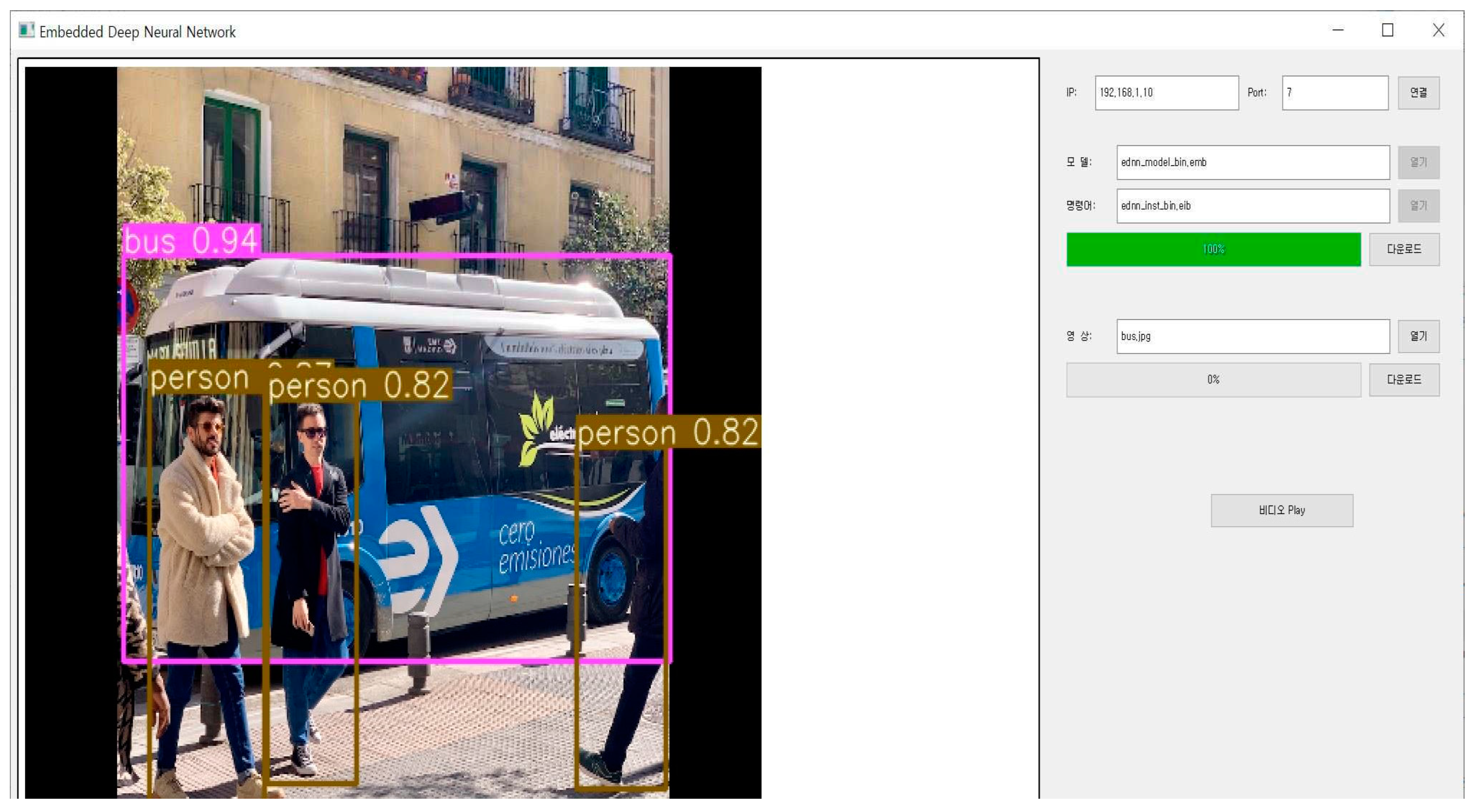
Figure 11 shows the test results of the CNN using YOLOv4-CSP-S-Leaky model for the object detection [
9]. It shows that the CNN accelerator detects three persons and one bus. Note that the comparison in terms of Mean Average Precision (mAP) is not included in this paper since the max-pooling operation is not the loss operation.
Figure 1.
Operating principle of the horizontal max-pooling engine with maximum possible window size K when incoming value xp(i,j) is r0 < xp(i,j) < r1 and the r3 is pushed out of the window.
Figure 1.
Operating principle of the horizontal max-pooling engine with maximum possible window size K when incoming value xp(i,j) is r0 < xp(i,j) < r1 and the r3 is pushed out of the window.
Figure 2.
Rank-counting block consisting of Rv blocks (v=0, 1, ..., K-1) and comparator blocks marked as ‘>’.
Figure 2.
Rank-counting block consisting of Rv blocks (v=0, 1, ..., K-1) and comparator blocks marked as ‘>’.
Figure 3.
Structure of Rv block consisting of the multiplexer, the multiplexer switch (MS), and the register rv.
Figure 3.
Structure of Rv block consisting of the multiplexer, the multiplexer switch (MS), and the register rv.
Figure 4.
Delay-counting block consisting of Dv (v=0, 1, ..., K-1), comparators marked as ‘=’, and OR gates.
Figure 4.
Delay-counting block consisting of Dv (v=0, 1, ..., K-1), comparators marked as ‘=’, and OR gates.
Figure 5.
Structure of Dv consisting of multiplexer, multiplexer switch (MS), and the register dv.
Figure 5.
Structure of Dv consisting of multiplexer, multiplexer switch (MS), and the register dv.
Figure 6.
Block diagram for the two-dimensional RTB-MAXP engine.
Figure 6.
Block diagram for the two-dimensional RTB-MAXP engine.
Figure 7.
The horizontal axis max-pooling operation of the CMB-MAXP engine with the scalable kernel size k.
Figure 7.
The horizontal axis max-pooling operation of the CMB-MAXP engine with the scalable kernel size k.
Figure 8.
The vertical axis max-pooling operation of the CMB-MAXP engine with scalable kernel size k.
Figure 8.
The vertical axis max-pooling operation of the CMB-MAXP engine with scalable kernel size k.
Figure 9.
The simulation result of the RTB-MAXP engine with k=5 and W=32.
Figure 9.
The simulation result of the RTB-MAXP engine with k=5 and W=32.
Figure 10.
The simulation result of the CMB-MAXP engine with k=5 and W=32.
Figure 10.
The simulation result of the CMB-MAXP engine with k=5 and W=32.
Figure 11.
The test results of our CNN accelerator employing the CMB-MAXP engine on the VCU118 platform.
Figure 11.
The test results of our CNN accelerator employing the CMB-MAXP engine on the VCU118 platform.
Table 1.
The relationships between the multiplexer switch (MS)’s input and output, and the output of the multiplexer exploited as Rv and Dv.
Table 1.
The relationships between the multiplexer switch (MS)’s input and output, and the output of the multiplexer exploited as Rv and Dv.
| Multiplexer Switch (MS) |
Multiplexer |
| Input |
Output |
Output |
|
mv-1
|
mv |
mv+1
|
nv |
cv[0] |
cv[1] |
rv |
dv |
| 0 |
0 |
X |
0 |
0 |
0 |
rv |
dv+1 |
| 0 |
1 |
X |
0 |
0 |
1 |
xp(i,j) |
0 |
| 0 |
1 |
X |
1 |
0 |
0 |
rv |
dv+1 |
| 1 |
0 |
X |
0 |
0 |
0 |
rv |
dv+1 |
| 1 |
1 |
X |
0 |
1 |
0 |
rv+1
|
dv+1+1 |
| 1 |
1 |
X |
1 |
0 |
0 |
rv |
dv+1 |
| X |
0 |
0 |
1 |
1 |
1 |
rv-1
|
dv-1+1 |
| X |
0 |
1 |
1 |
0 |
1 |
xp(i,j) |
0 |
Table 2.
Resource utilization of the RTB-MAXP engine and the CMB-MAXP engine with K=13 and W=32 implemented in Xilinx Vertex UltraScale+ FPGA XCVU9P.
Table 2.
Resource utilization of the RTB-MAXP engine and the CMB-MAXP engine with K=13 and W=32 implemented in Xilinx Vertex UltraScale+ FPGA XCVU9P.
| |
RTB-MAXP |
CMB-MAXP |
| UA |
UP |
UA |
UP |
| LUT |
158,515 |
13.4% |
28,765 |
2.43% |
| LUTRAM |
- |
- |
2,688 |
0.45% |
| FF |
99,342 |
4.2% |
76,906 |
3.25% |

