1. Introduction
The use of fiber-reinforced polymer (FRP) is one of the necessities and has become the natural development in reinforcing various structural elements such as slabs, beams, and columns. Many studies used FRP composites as an internal reinforcement or as an external strengthening, and it had an outstanding performance in resisting the loads on the various structural elements as stated and covered in previous studies, [
1,
2,
3,
4]. FRP generally has many advantages and few disadvantages, and it is generally well known in the academic community. However, FRP composite material is an excellent choice for exterior reinforcement due to its superior properties such as high stiffness and specific strength, ease of installation, applicability without disturbing the existing functionality of the structure, and the non-corrosive, and non-magnetic nature of the material along with its resistance to chemicals.
There is a scarcity of researches using basalt as a main reinforcement. However, the codes still lack complete information about basalt as reinforcement within the structural elements. Recently, researchers tended to study the behavior of basalt fiber reinforced polymer (BFRP) within the structural elements such as [
5,
6,
7]. The relevant results showed the distinctive performance of the BFRP, in addition to being environmentally friendly, has relatively stable properties compared to glass FRP (GFRP). Currently, there has been a tendency to use hybrid reinforcement, which is a double reinforcement of steel and FRP bars. This type of hybrid reinforcement is interesting at present, and there is a lack of research covering the structural behavior but [
8,
9,
10] studied the behavior of hybrid reinforcement for different structural elements and the results showed significant enhancement in the structural performance.
Reinforced concrete (RC) structures are sometimes subjected to modification during their service life, making web openings in RC. Beams are often required to accommodate basic services such as air conditioning ducts, water supplies, electricity, and heating ductwork. Transverse openings in the RC beams are a potential source of strength loss. Consequently, the openings in the existing RC beams lead to an interruption in the normal flow of stresses which reduces the beam's shear capacity and stiffness and leads to premature cracking of the concrete especially around the opening corners. Based on the
lo/
hc aspect ratio by [
11], where
lo is the opening's length and
hc is the larger of the opening's depth of the bottom or top chord, rectangular web openings in the shear zones of RC beams classified as small, large, or very large. Small openings are those with an aspect ratio of less than 1.5 whereas large openings with an aspect ratio of 1.5 to 4.0. However, very large openings for an aspect ratio of more than 4.0. Otherwise, [
12] studied the opened beam with large web openings. The study applied the direct stiffness method for solid and opened members. The relevant results showed that the deflection and support reactions have in excellent agreement with the [
13]. Hence, the approach provides adequate data for incorporating openings. Many researchers study the effect of drilling a hole through the beam web and the deterioration present in the shear capacity, which depends on the position of the hole and whether it passes through the path between the load and the support and finally leads to reducing the load capacity of the beam. Consequently, cracking and ultimate loads decreased, and enhancing action became more pronounced as opening dimensions increased. In order to prevent this decrease in shear and bending capacity, additional reinforcement must add around the opening in the form of internal reinforcement or external strengthening. [
14] stated that the stiffness and ultimate strength of the reinforced concrete beam decreased dramatically when an opening was present within its shear zone. Because of the concentration of stress, several cracks appear at the opening corners, and because of the lack of shear strength, diagonal cracks appear along the upper and lower chords. Failure in this instance occurs as a diagonal shear failure in the upper and lower chords. It is more effective to externally strengthen a beam opening with steel plates or carbon fiber reinforced polymer (CFRP) sheets than reinforce internally with internal steel reinforcement. The section at the opening is made stiffer by the external material and the material choice for external strengthening determines how much the section stiffness increases. In this direction, it has been emphasized that adding reinforcements to the area around the opening is a great method to restore the strength and stiffness of the beam. Numerous researchers have noted that this is necessary in order to mitigate the detrimental effects of stress concentrations around the openings and prevent the beam from failing prematurely. [
15] reported that the ultimate load capacity for the beams increases significantly if the openings are near the mid-span tension side or closer to the compression side near the supports. Furthermore, the ultimate load capacity of the beam is affected by a web opening at a high-moment side, and this opening affects the failure load. Moreover, the ultimate load capacity of beams with a large opening is lower than that of beams with several narrow openings having the same equivalent area. The results showed that by strengthening the openings corner sides, the ultimate load capacity of the beams increased. Also, if the length of the reinforcement provided at the bottom and top of the opening is insufficient for anchorage, horizontal web reinforcement should be added along the beam. [
16] noted that the opening size governs the beam failure, and FRP strengthening material doesn't enhance the ultimate load capacity of the opened beams. However, the beam capacity is reduced by 39% for an unstrengthened beam opening with a 100mm opening height and a 0.15 beam length width. Therefore, the maximum load capacity of an unstrengthened beam with an opening of 100mm width and a height of 0.38 is reduced by 33%. FRP-wrapped beams exhibit debonding of the FRP wrapping, which causes them to tear along the diagonal cracks. Also, initial cracks in the flexural zone instead of the opening zone cracks appeared in the FRP wrapping around the opening of the beams with 200mm and 300mm opening widths.
The beams are affected by the location, similarity, shape, and dimensions of the opening. Numerous studies were performed, and many crucial conclusions were recommended. [
17] investigated large square openings in the shear zone of RC beams located 0.5 and d (beam effective depth) distant from the support which caused a significant reduction in the beam capacity of about 74 and 69%, respectively. The results showed that the losses in beam strength caused by openings in shear at distances of 0.5d and d from the support were almost identical. With large square openings in the shear zone at distances of 0.5d and d, respectively, the CFRP laminates in the strengthening configuration are capable of restoring the beam strength to approximately 54% of the original structural capacity of the beams. From the comprehensive study by [
18] the beam strengthening with BFRP around and inside two circular openings with the same area is more efficient than the single circular openings having the same area. [
19] investigated the effect of the opening shape on the ultimate load capacity of the beam. The results showed that the opening reduces the load capacity of the beam by about 17% in circular openings, 19% in square,21% in rectangular,20% in hexagonal, and 18.4% in elliptical openings. [
20] noted that the test results are a trivial difference between opened beams and control beams up to an opening size of 100 mm in (length). In general, large-opening reinforced concrete beams (opening length of more than 100mm) in the shear zone lead to excessive shear cracks around the openings, and the failure mode is classified as a shear failure. Further, providing a large opening in the reinforced concrete beam reduced the ultimate load capacity by about 34%.
In the end, although there are several studies on the performance of solid beams and opened beams in the literature, there is not enough information or design guidance for beams with openings. However, FRP composites stiffen the beam either by externally bonding sheets with an adhesive or internally by reinforcing the beam around the openings. To increase the shear strength capacity and the ductility of the opened RC beam, it is necessary to increase the amount of reinforcement around the openings. Hence, the objective of this research is to investigate the structural behavior of simple beams with preformed main hybrid reinforcement having symmetrical rectangular openings in both edges at a distance of 250mm (i.e., equal to the effective depth) from the support. To cover the experimental parameters, six RC beams were cast to cover the studied parameters. The studied parameters included the effect of using internal reinforcement (steel or BFRP bars) provided along the opening, or by incorporating an external BFRP sheet around the opening which is known as the external sheeting wrap. The double enhancement of the beam with internal steel reinforcement bars in addition to the external strengthening BFRP sheet was also investigated. Ultimately, the experimental results are compared with numerical results to verify the evidence of the relevant results and recommendations.
2. Properties of Used Materials
Portland Cement type CEM I – 42.5N was tested and verified according to [
21].
Table 1 shows the obtained results of the used cement in this study. Also,
Table 2 and
Table 3 summarized the physical and mechanical properties of the coarse aggregate (crushed stone) and fine aggregate (sand), respectively which prove the compliance with [
22]. Tap drinking water free from impurities was used in concrete mixing and curing. However, steel reinforcement such as mild steel (φ) or high-grade steel (Φ) was tested to verify the mechanical properties according to [
23]
, and
Table 4 shows the relevant results. The uniaxial tensile test carried out on the BFRP bars according to [
24,
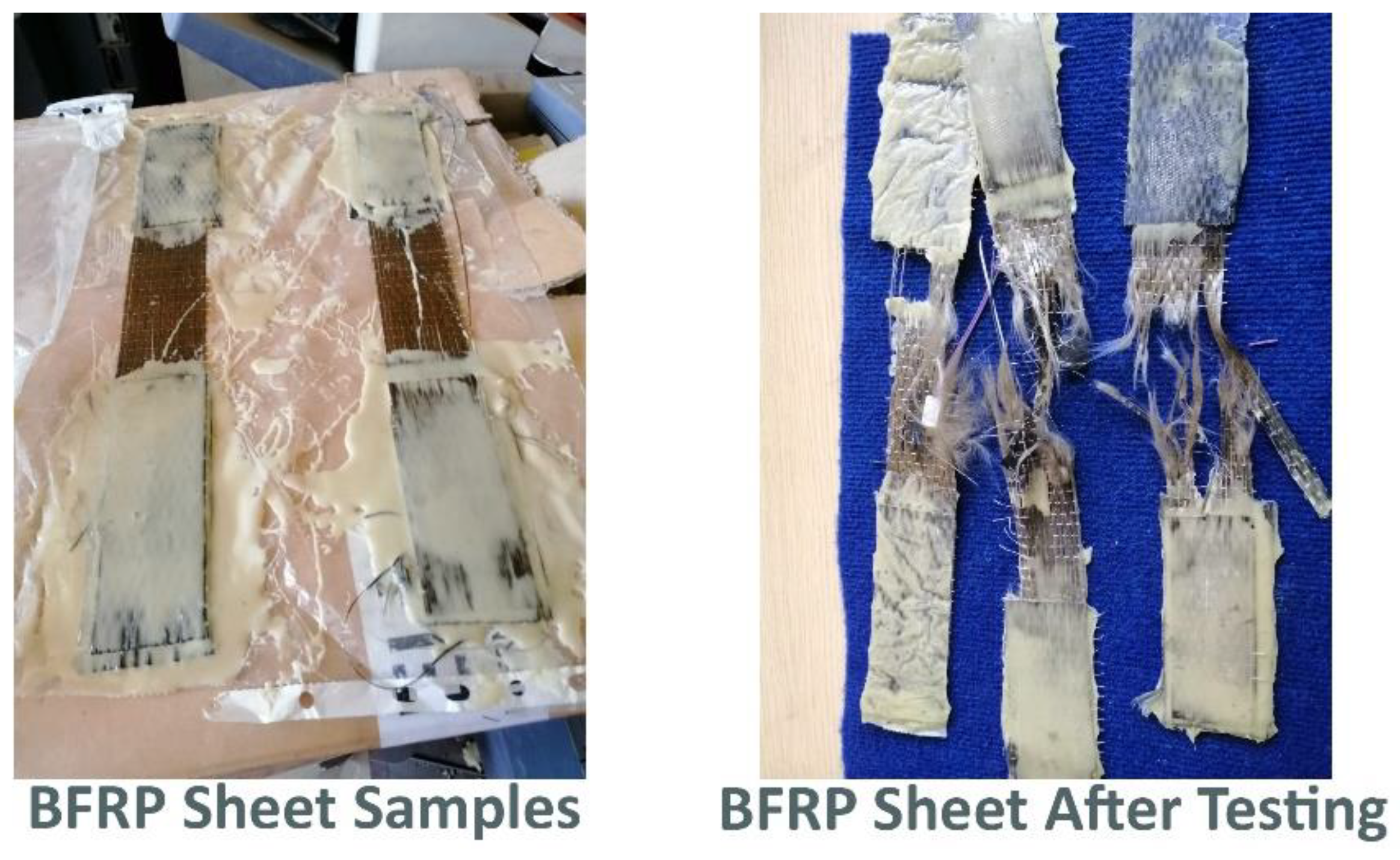
25], the ultimate rupture strength and modulus of elasticity of the 10-mm-diameter BFRP bars were 1086MPa and 48.1GPa, respectively and the basalt fiber content was 60% of the cross-sectional area. Likewise, the corresponding values for the 0.111-mm-thickness BFRP sheet were 2100MPa and 91GPa, respectively, see
Figure 1.
Figure 1.
BFRP Sheet Samples Before and After Tensile Strength Testing.
Figure 1.
BFRP Sheet Samples Before and After Tensile Strength Testing.
Table 1.
Physical and Mechanical Properties of Cement.
Table 1.
Physical and Mechanical Properties of Cement.
| Property |
Result |
Acceptable Limit[21] |
| Fineness (cm2/gm) |
3283 |
- |
| Specific Gravity |
3.14 |
- |
| Expansion (mm) |
1.7 |
Not more than 10mm |
| Initial Setting Time (minutes) |
143 |
Not less than 60minutes |
| Final Setting Time (minutes) |
218 |
- |
| Compressive Strength (MPa) |
2 days |
24.1 |
Not less than 10MPa |
| 7 days |
36.3 |
- |
| 28 days |
56.1 |
Not less than 42.5MPa andnot more than 62.5MPa
|
All beams were cast using the same concrete mix with a target compressive strength of 35MPa and designed according to [
26]. Concrete quantities of the used ingredients were cement content (450kg/m3), coarse aggregate (1126kg/m3), fine aggregate (608kg/m3), and water content (202kg/m3). However, trial mixes were cast to verify the compressive strength of the concrete, and the concrete mix achieved the design value (35MPa). Therefore, after testing the RC beam mixes, the average results were 32.5MPa after 28 days.
3. Experimental Program
The experimental program of this research comprised a total of six beams, as summarized in Table 5. All beams had constant cross-sections of 150mm x 300mm and a clear span and total length of 1800mm and 2000mm, respectively. The tensile reinforcements of all beams consisted of two deformed steel bars of 10mm diameter (0.67 of the reinforcement area) and one deformed BFRP bar of 10mm diameter (0.33 of the reinforcement area). Further, the secondary compression reinforcements were two steel bars of 10mm diameter. The solid parts and the upper and lower cords of the openings of all beams were confined with 8-mm-diameter closed steel stirrups spaced at 150mm.
The six tested beams included one solid beam without openings (i.e., control specimen: BSF), and the other beams schemed with two symmetrical large rectangular openings of 250mm length and 150mm depth located at the shear spans of 250mm from the supports. Out of the five beams with openings, one beam was tested without enhancement (BSFO), and the other four were enhanced with different combinations of additional internal steel or BFRP bars and external strengthening bonded BFRP sheets around the openings. The BSFO-IS beam was enhanced with two vertical and horizontal steel bars of 10mm diameter adjacent to the four edges of the openings. Likewise, the BSFO-IF beam was enhanced internally with BFRP bars of 10mm diameter. The BSFO-EF beam was enhanced by bonding one external layer of BFRP sheets in the horizontal and vertical directions around the openings. The last enhanced beam (BSFO-IS-EF) contained the internal steel bars and the external strengthening BFRP sheets around the openings. Details of the specimens in elevation and cross sections are shown in
Figure 2,
Figure 3,
Figure 4,
Figure 5,
Figure 6 and
Figure 7, respectively.
Table 5.
Details of the tested specimens.
Table 5.
Details of the tested specimens.
| Beam Code |
Bottom bars |
Compression steel bars |
Steelstirrups
|
Opening Enhancement |
| Steel |
BFRP |
InternalSteel bars
|
Internal BFRP bars |
External BFRP sheet |
| BSF |
2Ф10 |
1Ф10 |
2Ф10 |
φ8@150 mm |
- |
- |
- |
| BSFO |
- |
- |
- |
| BSFO-IS |
2Ф10 |
- |
- |
| BSFO-IF |
- |
2Ф10 |
- |
| BSFO-EF |
- |
- |
75-mm-width |
| BSFO-IS-EF |
2Ф10 |
- |
75-mm-width |
3.1. Installation of the BFRP sheet, and Test Setup of Beams
The installation process has started for the BSFO-EF and BSFO-IS-EF beams after fourteen days from cast in order to ensure the beam drying after seven days of water curing. Epoxy [
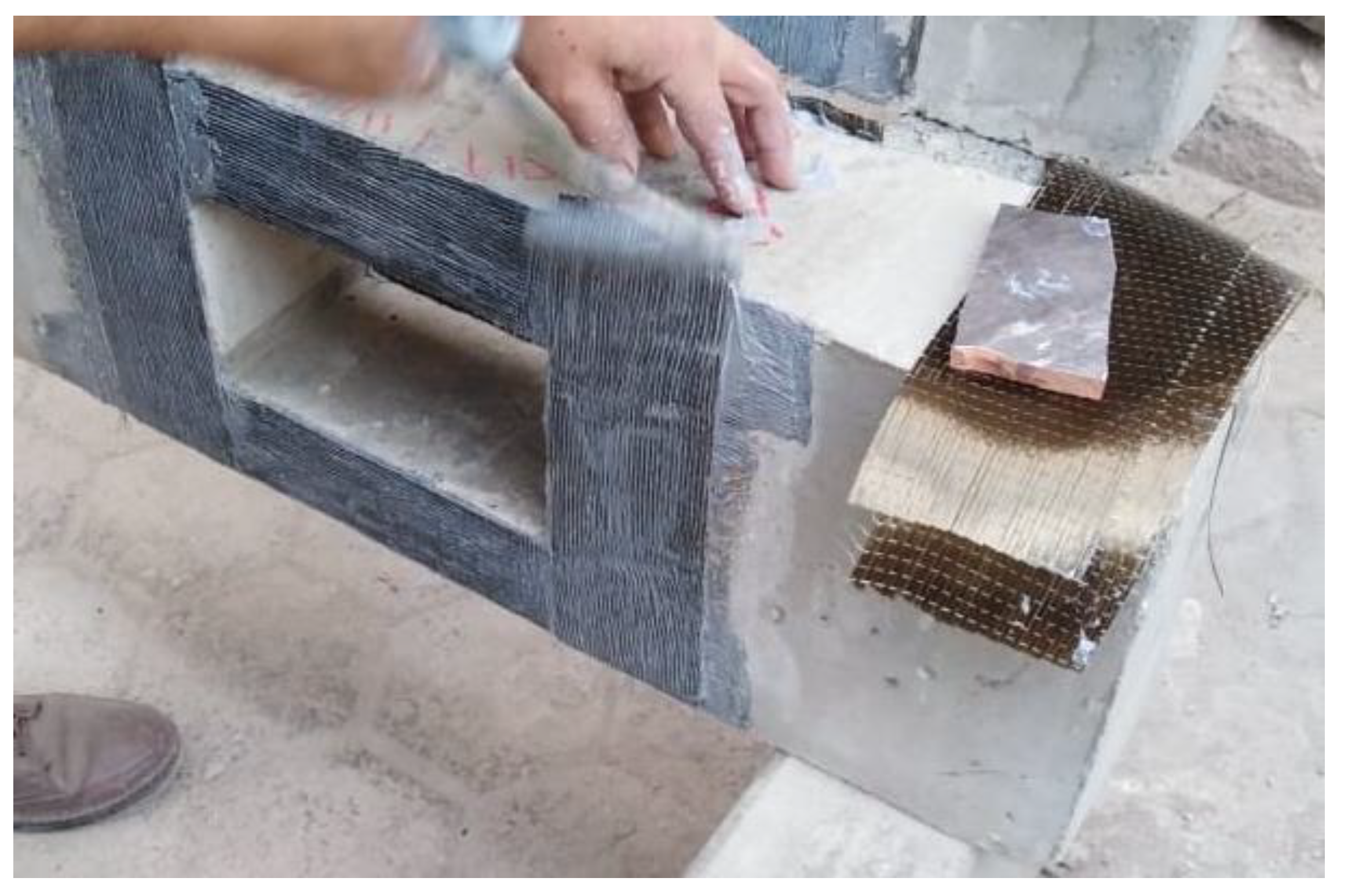
28] with two components (A+B) has been used as an epoxy to glue the BFRP sheets around the beam opening corner. The steps of application of the BFRP sheet are as follows: The concrete surface around the beam opening was roughened; the epoxy was applied to the concrete surface; the horizontal BFRP sheet was glued followed by the vertical BFRP sheet to confirm overlap in the vertical direction, See
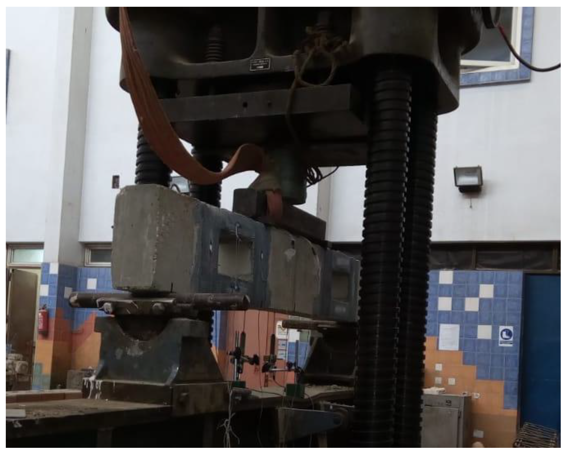
Figure 8. All beams were tested under a four-point flexural loading setup, where the total applied load was divided into two equal monotonic loads resisted by two points of the beam supports. The mid-span vertical deflection was measured and recorded during the test using a linear vertical displacement transducer (LVDT), see
Figure 9.
Figure 8.
Installing of the BFRP Sheet.
Figure 8.
Installing of the BFRP Sheet.
Figure 9.
Loading and Test Setup for the tested Beams.
Figure 9.
Loading and Test Setup for the tested Beams.
4. Numerical Nonlinear Finite Element Modeling
Nonlinear three-dimensional finite element modeling (NL 3D FEM) using ANSYS software package version 15 was adopted to simulate the structural behavior of the tested beams. However, the characterization of the developed model was illustrated in detail in the previous studies of the author [
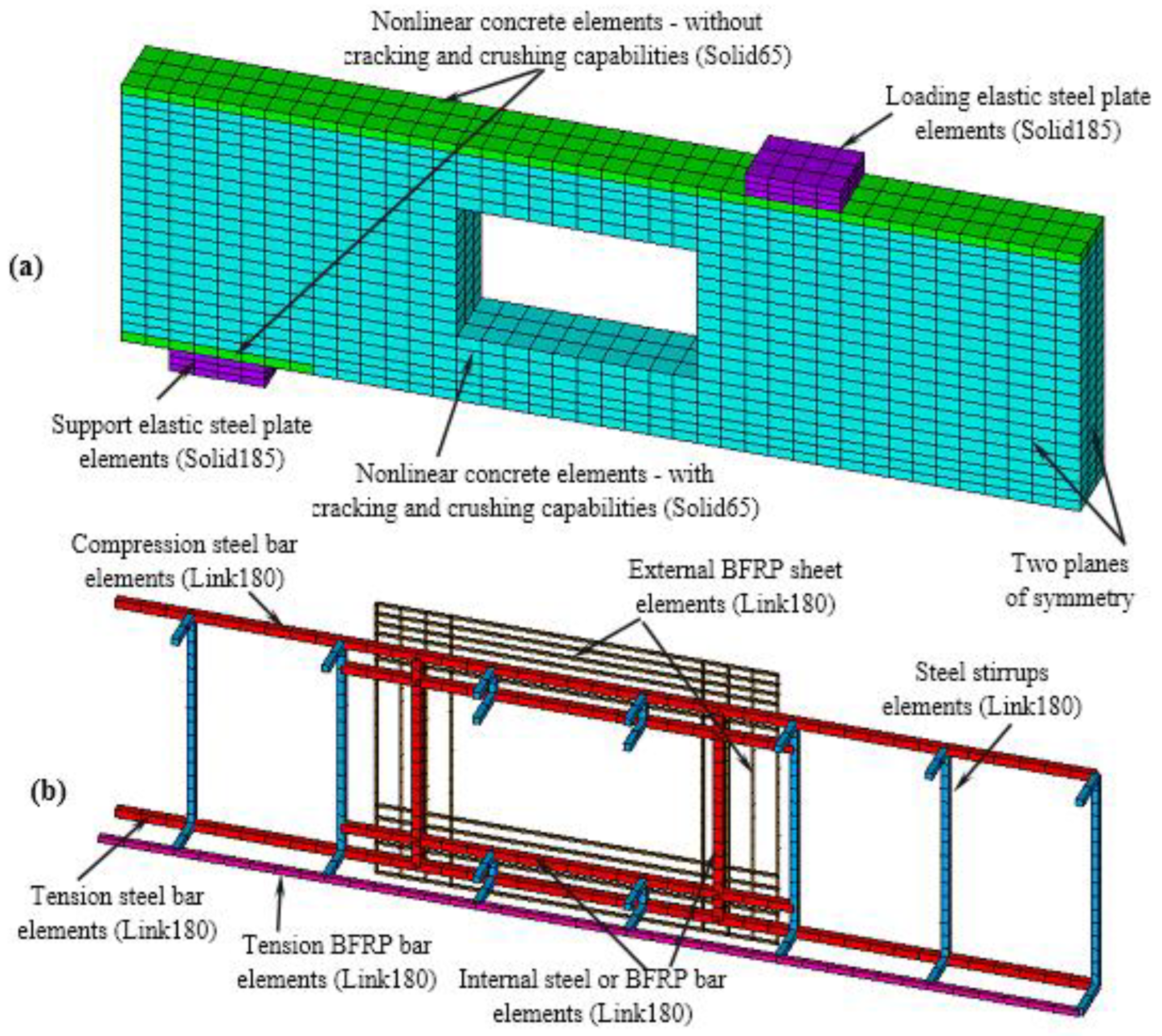
29]. Based on the identical conditions of the materials, loading, and supports in both the longitudinal and transverse directions, only a quarter of FE models were created for the beams, as shown in
Figure 10. Through the developed models, concrete was modeled using the SOLID65 element. This element has the capability of plastic deformations, cracking, and crushing in three orthogonal directions. SOLID185 element also has the plastic deformation capability and was idealized here to simulate the behavior of loading and support plates to avoid the stress concentrations at these locations. As for the steel and BFRP reinforcements in the longitudinal and transverse directions and the BFRP sheet that externally bonded around the openings, the 3D structural element; LINK180 bar element was adopted to simulate their behaviors. This element has three degrees of freedom in the three Cartesian directions and has the capability of plastic deformations. To consider the bonding behavior between the steel and BFRP bars and the surrounding concrete, the zero length-spring element (COMBIN39) was adopted in this study with the aid of the bond-slip models of both steel and BFRP bars developed by the authors in previous studies [
30]. Moreover, the perfect bond was assumed between the BFRP sheets and concrete.
To simulate the nonlinearities of the used materials, the proper material models were defined. The MacGregor model [
31]
, and the ACI model [
13] were adopted to define the concrete nonlinear behavior in compression and tension, respectively. Furthermore, open and closed shear coefficients were defined as 0.4 and 0.9, respectively. In order to avoid convergence difficulties, the crushing capability was neglected for the concrete elements adjacent to the loading and support plates. On the other hand, the steel and BFRP properties were defined as elastoplastic and uniaxial elastic material models, respectively. Finally, the rigid steel plates were simulated as elastic materials. More details regarding the definitions of the material used were presented in the study [
32,
33,
34,
35]. Similar to the experimental program, the modeled beams were investigated under the effect of four bending flexural loading systems. The applied load for the RC beam was divided into many substantial steps adopting an automatic time-stepping technique to determine the proper load step sizes. Furthermore, the well-known Newton-Raphson equilibrium iteration approach was adopted to satisfy the tolerance of convergence criteria.
5. Results, Analysis, and Discussion
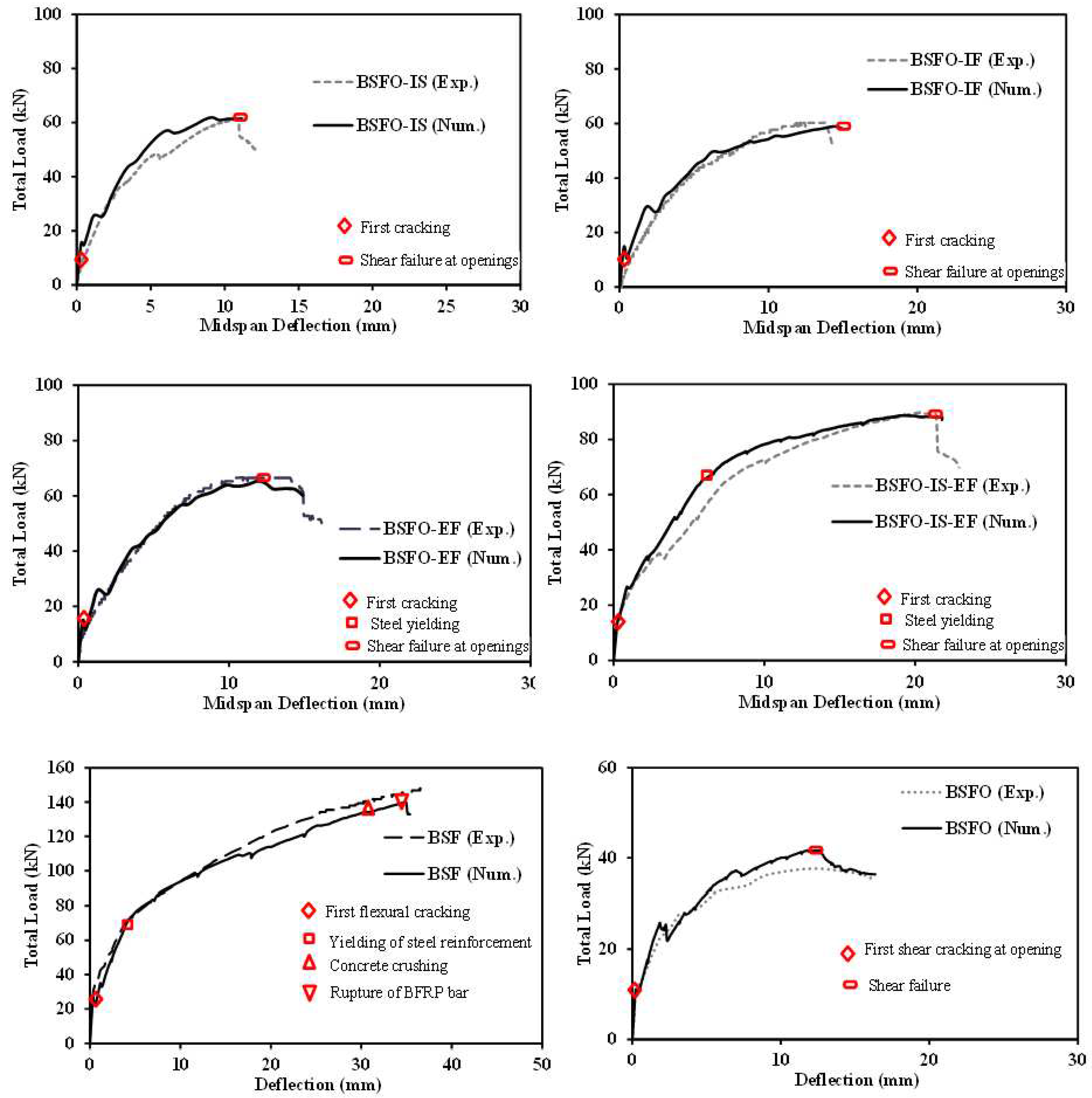
Table 6 shows the relevant numerical and experimental results. For the cracking stage, the numerical cracking load and vertical deflection were compatible with the experimental load and vertical deflection by almost 91.30% to 117.20% and 95.54% to 104.20%, respectively. In the yielding stage, the numerical yielding load and vertical deflection were compatible with experimental load and vertical deflection by almost 100.43% to 104.12% and 87.01% to 105.26%, respectively. Therefore, in the peak stage, the numerical maximum load and vertical deflection were compatible with experimental load and vertical deflection by almost 94.15% to 110.08% and 95.89% to 108.70%, respectively. Wherefore, the numerical model confirms the relevant experimental results.
Figure 11 shows the relationship between the total load versus mid-span vertical deflection for all tested beams. The numerical results curves have the same trend as the experimental curves. The curve was linear up to the first crack with higher elastic Young’s modulus followed by decreasing in the line slope which lead to decreasing the tangent Young’s modulus for BSF, and BSFO-IS-EF beams until the end of the yielding stage. Moreover, the peak stage started, and crushing in concrete happened. Afterward, the beam failed due to the rupture of BFRP bars in the BSF beam while the BSFO beam failed by shear due to the presence of the openings. On the other hand, the other opened beams don’t reach the yielding stage due to strength loss in the shear zone. However, the concrete started to lose its strength (decreasing in the slope of the curve) that appeared significantly in the experimental and numerical curves until reached the shear failure due to the presence of the openings.
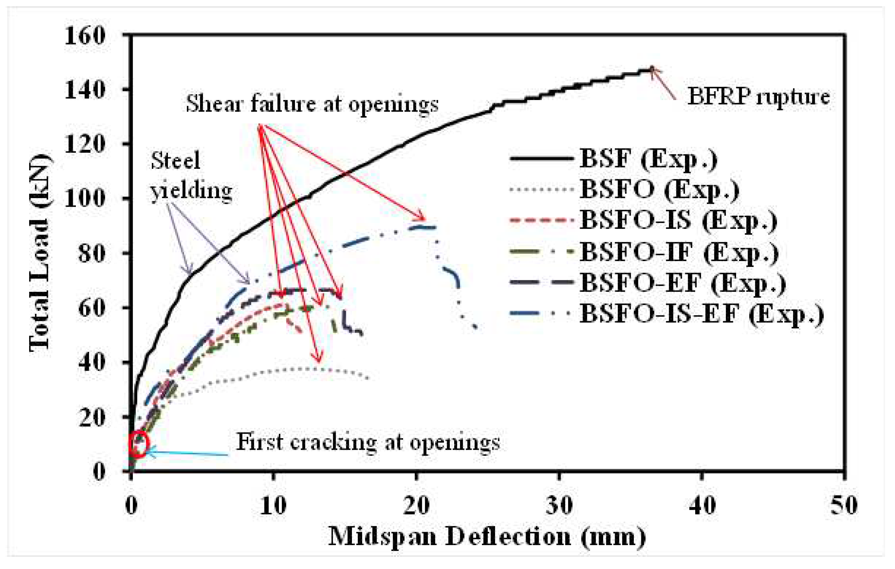
Table 7 and
Figure 12 show the relationship between load versus vertical deflection curves for the tested beams. The BSF solid beam showed a linear relationship up to the first cracking load of 30kN followed by steel yielding load of 69kN. Afterward, concrete is crushed at the top fiber of the beam. Finally, the BFRP bars ruptured at the maximum load of 148.8kN. The beam behavior was affected by the contribution of the FRP reinforcement and confirmed by the ratio between the maximum load to the yielding load of 5.43 times. That could be because of the FRP bar's contribution to boosting the beam strength and post-yielding stage. Beyond the yielding stage, the FRP reinforcement contribution became significant and controllable. The post-yielding stiffness was clear positive realized up to failure. At failure, excessive deep cracks and crushing appeared at the mid-top fiber of the beam. The absorbed energy was larger than the other tested beams due to the failure of all resisting elements sequentially (yield of steel, crushing in concrete, and rupture of BFRP). Therefore, the beam achieved the optimum values for stiffness and ductility compared with the other opened beams. The BSFO beam showed a linear relationship between the total load versus the vertical deflection curve up to the cracking load of 11.5kN, and the first crack appeared around the opening corner. However, the crack distribution increased superior and propagated widely due to a reinforcement lack around the opening corner. The maximum load was 37.7kN. Consequently, opening without internal reinforcement or external strengthening reduced the maximum load by 74.66%, in addition to changing the beam crack pattern to shear failure in the opening zone.
The BSFO-IS beam with internal steel-reinforced openings showed a linear behavior up to the cracking load of 9.3kN (less than the BSFO beam). That means internal steel reinforcement about the beam opening doesn’t resist any stresses till the first crack. Yield load was missing, and the maximum load was 61.1kN. Also, the absorbed energy increased compared with the BSFO beam due to placing the internal steel reinforcement around the opening’s corner and leading to post-the-crack propagation. Therefore, the BSFO-IF beam reinforced with internal BFRP around the opening’s corners showed almost the same performance. The cracking and maximum loads were 10.0kN and 60.2kN, respectively (closer to the BSFO-IS beam). Using the external BFRP sheet to strengthen the opening’s corners enhanced the performance of the BSFO-EF beam. At the cracking stage posted, the cracking load reached 12.6kN, and the maximum load was 66.5kN. That means the beam gains more strength and absorbs more energy than beams with internal reinforcement whether reinforced with steel or BFRP bars.
Enhancing the beam with steel bars around the beam opening and external BFRP sheet in the BSFO-IS-EF beam increased the structural performance than BSFO-EF beam. The cracking, yield, and maximum loads were recorded at 15.0kN, 65.6kN, and 89.5kN, respectively. The internal steel reinforcement and external BFRP sheet around the opening’s corner arrested the crack speared and posted the crack propagation. The absorbed energy increased more than the other opened beams but decreased by 65.07% compared with the solid beam.
5.1. Crack Pattern and Failure Mode
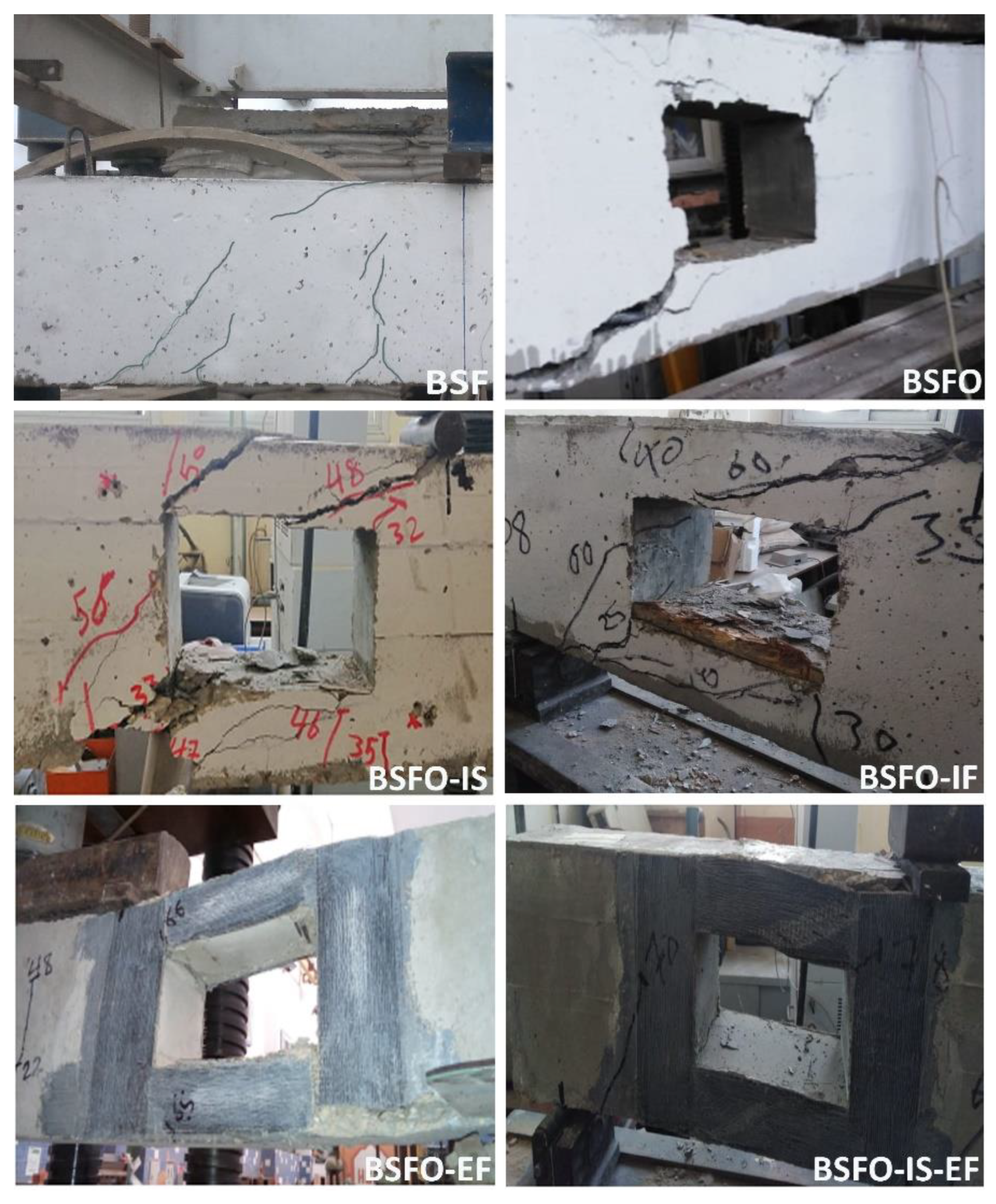
The first flexural crack propagated at the tension fiber of the mid-span in the BSF beam followed by excessive cracks that appeared widely after the yielding of the steel bars. The concrete top fiber was crushed followed by the BFRP bars rupture. On the other hand, the BSFO beam failed due to the shear mode in the beam opening. That confirms by appearing of the first cracks around the opening corner. Excessively, the crack was widened due to stress concentrations around the beam opening. The crack distribution decreased by reinforcing the opening’s corner internally. However, this reduction appeared significantly in the other tested beams. For the BSF-IS and BSF-IF beams, the crack width decreased compared with the BSFO beam. Finally, the beams failed in the shear mode. Therefore, the BSFO-EF beam arrested crack propagation and reduced crack distribution. This beam achieved the desirable performance in crack control. To improve crack control, the BSFO-IS-EF beam is highly recommended in this mission as it prevents damage even after failure.
Figure 13 shows the focused shear zone area for comparative experimental crack patterns of different beams. It was worth mentioning that the crack pattern for the numerical model was compatible with the experimental crack distribution.
6. Design Guidelines for the Opened Beams
In this section, the relationship between the opened area of the beam, and the added reinforcement around the opening was calculated.
Table 8 shows the added reinforcement to the opening area ratio of the different opened beams. It appeared that by increasing the reinforcement ratio, the maximum load increased. Despite that, the reinforcement ratio for the BSFO-EF beam being the lowest value, the beam achieved higher structural performance compared with the opened beam with internal reinforcement, whether reinforced with steel or BFRP bars. Hence, using the external BFRP sheets instead of internal reinforcement is highly recommended.
7. Conclusions
The conclusion is summarized as follows from the aforementioned experimental and numerical results:
- The numerical model achieved identical experimental results with variations ranging (from 8.70% to +17.20%) and (-5.85% to +10.08%) for cracking and the maximum loads, respectively.
- Hybrid reinforced solid beam invests the strength of all included materials such as steel bars and BFRP bars. The beam failed by steel yielding, and the concrete crushed followed by the rupture of the BFRP bars. Hence, the steel reinforcement and the BFRP bars provide the beam strength in ascending strength level order. Evidently, the solid beam gives the optimum solo desirable stiffness and deformability behaviors.
- For the same added internal reinforcement ratio, the maximum load for beams with internal reinforcement (steel or BFRP bars) was varied with trivial value, and the absorbed energy increased by 8.60% in the case of internal BFRP bars concerning internal steel reinforcement bars.
- Using the external BFRP sheet to strengthen the opening’s corners enhanced the performance of the opened beam by 8.84% and 10.47% compared with opened beams with internal steel or BFRP bars, respectively.
- By doubling the openings enhancement with internal steel bars and external BFRP sheet, the maximum load increased by 137.40% compared with the unenhanced opened beam, and the maximum load increased by 46.48% and 48.67% in comparison to the opened beams reinforced internally with steel or BFRP bars, respectively. Further, the maximum load increased by 34.59% concerning the opened beam enhanced externally with the BFRP sheet only.
- The absorbed energy improved significantly for the opened beam with internal steel bars and the external BFRP sheet by 190.70% compared with the unenhanced opened beam. Furthermore, the absorbed energy increased by 162.99% and 142.17% compared with the beams reinforced internally with steel or BFRP bars, respectively. Moreover, the maximum load increased by 184.65% concerning the opened beam enhanced externally with the BFRP sheet only.
- Using the external BFRP sheets instead of the internal reinforcement or doubling the enhancement with internal reinforcement and external strengthening with a BFRP sheet is highly recommended to enhance the maximum load and the absorbed energy.
- Enhancing the opening’s corners with internal reinforcement reduced the crack propagation and posted the beam failure. Therefore, the opened beam strengthened externally with the BFRP sheet arrested the crack propagation, and reduced crack distribution. However, doubling the openings enhancement with internal steel bars and external BFRP sheets improved crack control and prevented beam damage even after failure.
Funding
This research received no external funding
Data Availability Statement
The data that support the findings of this study are available from the corresponding author upon reasonable request.
Conflicts of Interest
The authors declare no conflict of interest.
References
- Yehia Sameh, (2018), “Experimental and Theoretical Study on Strengthened Low Compressive Strength Deficient Columns”, International Journal of Engineering Research (IJER), Volume 7, Issue 4, April, 2018.
- Ali Tarek, and Yehia Sameh (2016), “Study on Strengthening of RC Slabs with Different Innovative
Techniques”, Open Journal of Civil Engineering, 2016, 6, pp: 516-525. [CrossRef]
- A. Elsayed Tarek, F. Hanna Nagy, M. Ghanem Gouda, and Yehia Sameh, (2009), “Behavior of Short RC Columns Reinforced with FRP Bars”, News of the Kazan State University of Architecture and Engineering Journal, ISSN:2073-154X, 2(12), 2009.
- Ghanem Gouda, Abd El-Bakey Sayed, Ali Tarek, and Yehia Sameh, (2016), “Behavior of RC Beams Retrofitted/Strengthened with External Post-Tension System”, International Journal of Civil, Mechanical and Energy Science (IJCMES), 2, 36-43.
- Yehia Sameh, Abdelbaky Sayed, Moubarak Abdullah, M. Ibrahim Arafa, (2023), “Experimental and
Analytical Codes Comparative Study for Enhanced BFRP R.C. Columns Under Different Types of
Loading”, International Review of Civil Engineering (IRECE), Volume 14, Issue 3, 2023. [CrossRef]
- Abd El-Baky Sayed, Yehia Sameh, M. A. Ibrahim Arafa, and Moubarak Abdullah, (2021), “Behavior of
Columns Reinforced with BFRP Bars in case of Centric and Eccentric Conditions”, International Journal of
Scientific & Engineering Research -IJSER, Volume 12, Issue 1, January 2021.
- Abd El-Baky Sayed, Yehia Sameh, M. A. Ibrahim Arafa, and Haded Abdullah, (2021), “Effect of BFRP Post
Tensioning System on Hybrid Reinforced Concrete Slab”, International Journal of Scientific & Engineering
Research -IJSER, Volume 12, Issue 1, January 2021.
- M.A. Ibrahim Arafa, Wu Zhishen, M. , F. M. Fahmy Mohamed, and Doaa Kamal, (2016), “Experimental
Study on Cyclic Response of Concrete Bridge Columns Reinforced by Steel and Basalt FRP
Reinforcements”, Journal of Composites for Construction, Volume 20, Issue 3. [CrossRef]
- Said Hemdan, Hassanean Mahmoud, Hassanean Yahia, and Ibrahim Arafa, (2023), “Flexural Behavior of
Concrete Box Girders Reinforced with Mixed Steel and Basalt Fiber-Reinforced Polymer Bars”, Article
1, Volume 51, Issue 4, July and August 2023, Page 223-241
. [CrossRef]
- Said, H. , Hassanean, M., Hassanean, Y., Ibrahim, A. (2023). 'Flexural Behavior of Concrete Box Girders Reinforced with Mixed Steel and Basalt Fiber-Reinforced Polymer Bars', JES. Journal of Engineering Sciences, 51(4), pp. 223-241. [CrossRef]
- M. Elsanadedy Hussein, A. Al-Salloum Yousef, H. Almusallam Tarek, O. Alshenawy Abdulhafiz, Abbas
Husain, (2019), “Experimental and numerical study on FRP-upgraded RC beams with large rectangular
web openings in shear zones”, Construction and Building Materials, Volume 194, 2019, Pages 322-343. [CrossRef]
- Pertiwi D, Komara I, Fristian R, (2021), “Design concept of reinforced concrete beams with large web
Openings”, ICATECH 2020, IOP Conf. Series: Materials Science and Engineering, 1010 (2021) 012039. [CrossRef]
- ACI CODE-318-19(22): “Building Code Requirements for Structural Concrete and Commentary” (Reapproved 2022), American Concrete Institute.
- Said, M. Allam, (2005), “Strengthening of RC beams with large openings in the shear zone”, Alexandria Engineering Journal, Vol. 44 (2005), No. 1, 59-78 59.
- Torunbalci Necdet, (2011), “Behaviour and Design of Large Rectangular Openings in Reinforced Concrete
Beams”, Architectural Science Review, 45:2, 91-96. [CrossRef]
- Subhajit Mondal, Bandyapadhya J.N, Chandra Pal Gautam (2011), “Strengthening and rehabilitation of reinforced concrete beams with Opening”, International Journal of Civil and Structural Engineering, Volume 2, No 1, 2011.
- Chin, S.C. , Shafiq N. and Nuruddin M.F. (2012), “Strengthening of RC Beams with Large Openings in Shear by CFRP Laminates: Experiment and 2D Nonlinear Finite Element Analysis”, Research Journal of Applied Sciences, Engineering and Technology 4(9): 1172- 1180, 2012, ISSN: 2040–7467, Maxwell Scientific Organization, 2012. [Google Scholar]
- Sunder S Surya, Babu Nisha, Paulose Dinu (2016), “Experimental Study on Strengthening of Openings in
R.C Beams using BFRP Fabric”, International Journal of Innovative Research in Science, Engineering and
Technology, Vol. 5, Issue 8, August 2016.
- S Pillai Swathy, and Johny Alice (2018), “Analytical Study on Shear Behavior of Reinforced Concrete Beam with Varying Shapes of Web Opening”, International Journal of Engineering Research & Technology (IJERT), Special Issue – 2018.
- Muyasser, M. Jomaah, Diyaree J. Ghaidan (2019), “Energy Absorption Capacity of Layered Lightweight Reinforced Concrete Beams with Openings in Web”, Civil Engineering Journal, Vol. 5, No. 3, March, 2019.
- Egyptian Standards, ES:4756-1/2022, “Egyptian Standards for Cement”, Egyptian Organization for Standards & Quality.
- Egyptian Standards, ES:1109/2021, “Egyptian Standards for Natural Aggregate”, Egyptian Organization for Standards & Quality.
- Egyptian Standards, ES, 262-2021, “Egyptian Standards for Steel Reinforcement”, Egyptian Organization for Standards & Quality.
- ACI:440.3R-12, “Guide Test Methods for Fiber-Reinforced Polymer (FRP) Composites for Reinforcing or Strengthening Concrete and Masonry Structures”, American Concrete Institute Committee Report.
- ASTM D7205/D7205M-06, “Standard Test Method for Tensile Properties of Fiber Reinforced Polymer Matrix Composite Bars”, American Society for Testing and Materials.
- BS: 8500:2019, “British Standard for Concrete Mix Design”, Concrete –Complementary British Standard to BS EN 206.
- ASTM A615, A615M-04A, “Standard Specification for Deformed and Plain Billet-Steel Bars for Concrete Reinforcement”, American Society for Testing and Materials.
- Sikadur 330, data sheet, www.sika.com.
- Arafa M.A. Ibrahim, Hesham M. Diab, Yehia A. Hassanean, Omar A. Farghal, Mustafa M.A. Ismail, (2023),
“Numerical study on the behavior and strength of concrete beam strengthening with fiber reinforced
concrete jackets”, Structures, Volume 50, 2023, Pages 1557-1572, ISSN 2352-0124. [CrossRef]
- Yehia Sameh, Ali Tarek, and El Didamouny Mohamed, Forthcoming, “Structural Behavior of Concrete
Slabs with Profiled Metal Decking - Experimental and Analytical Study”, Practice Periodical on Structural
Design and Construction. [CrossRef]
- K. Wight James, and G. MacGregor James, (2011), “Reinforced Concrete Mechanics and Design”, 6th Edition Prentice Hall (2011).
- Aly Tarek, Yehia Sameh, M. Ahmed Ahmed, and Hassaan Osama, (2020), “3D-Modelling of Stratified
Reinforced Concrete Slabs”, International Journal of Scientific & Engineering Research -IJSER, Volume 7,
Issue 7, July 2020.
- M.A. Ibrahim Arafa, F.M. Fahmy Mohamed, and Wu Zhishen, (2016), “3D finite element modeling of bondcontrolled
behavior of steel and basalt FRP-reinforced concrete square bridge columns under lateral
loading”, Composite Structures, Volume 143, 2016, Pages 33-52, ISSN 0263-8223. [CrossRef]
- Yehia Sameh, M. A. Ibrahim Arafa, and Faihan Badr, (2021), “Experimental Study on Steel-FRP Reinforced
Concrete Beams with Large Rectangular Openings”, International Journal of Scientific & Engineering
Research -IJSER, Volume 12, Issue 1, January 2021. 20 January.
- Yehia S, Aly T, Hassan O. (2021), “An experimental and numerical study for investigating the promising
stratified reinforced concrete slabs”, Advances in Structural Engineering. 2021;24(12):2826-2840. [CrossRef]
|
Disclaimer/Publisher’s Note: The statements, opinions and data contained in all publications are solely those of the individual author(s) and contributor(s) and not of MDPI and/or the editor(s). MDPI and/or the editor(s) disclaim responsibility for any injury to people or property resulting from any ideas, methods, instructions or products referred to in the content. |
© 2023 by the authors. Licensee MDPI, Basel, Switzerland. This article is an open access article distributed under the terms and conditions of the Creative Commons Attribution (CC BY) license (http://creativecommons.org/licenses/by/4.0/).
