1. Introduction
The use of industrial robotic systems in various arc welding applications is quite frequent [
1,
2,
3,
4]. However, these systems occupy an operational space that is generally large, in addition to the industrial robotic system, many are mounted on mobile equipment with several axes [
5,
6]. In addition to these systems, sometimes they use positioners for the structure, which allows for improvements in the way the structure is welded [
7,
8]. A robotic welding system typically works suspended from the ceiling and is very expensive, but despite the costs, these systems are highly efficient, which allows for increased productivity in companies, the greater the number of robots installed for this type of process, the greater the productivity, however, there are many other challenges, for example, if the welding times between different robots are not identical, it can cause waiting times between different robots, and for systems with multiple robots, it is necessary to study the reduction these waiting times. Another challenge in this type of work is the deformation of the parts due to welding for a prolonged period, for this reason, sensors are installed in robotic systems to detect the position of the start of welding and arc sensors to correct the deviation during the welding process [
9,
10].
The inclusion of collaborative robotic systems (Cobot) is due to several factors, in particular the ease of use and installation of this type of equipment, in addition to these factors, these systems have excellent flexibility and efficiency [
11,
12,
13]. In welding tasks, the possibility of using Cobots allows more flexibility in different welding tasks, in addition to allowing specialized technicians to easily interact with one or even several Cobots at the same time, so it is possible to change paths more quickly, prepare the different setups of the various welding processes, significantly improving the performance of the jobs [
14,
15,
16,
17]. The main objective of using Cobots is to combine the performance of this system with the capabilities of a human being [
18]. The integration of Cobots allows for a more intuitive solution for the technical specialist, obtaining practically the same functionalities as an industrial robot, but with the advantages of Cobots, even losing the main function of a collaborative robot, but gaining a cooperation function in the process.
Human-Robot Collaboration (HRC) is a new trend in this type of application, the main objective is to build a safe collaboration environment between humans and robotic systems. In all types of work, there are work zones, between manual production and fully automated production, in this zone the human worker can interact with a machine [
16,
17,
18]. However, this work zone has many limitations due to security restrictions [
22,
23,
24,
25]. For example, when using an industrial robotic system, the system only works if the staff is outside the manufacturing cell. In collaborative robotics, people can share the workspace, so that it can help in non-ergonomic operations, repetitive operations, or even uncomfortable or even dangerous operations.
It is obvious that any robot, through its installed sensors, can monitor its movements, limit its speed at any time, or even stop performing a certain task. The possibility of using a workspace without safety fences can improve productivity and maximize space for companies. The idea is to extend this concept to different robotic applications, mainly those that have not yet been automated. We can see these types of robotic systems as robotic assistants to improve the quality of human work. [
24,
25].
Other researchers have developed a low-cost system for identifying shapes (contours) through a digital camera coupled to the robot, to program industrial robots for welding but only work in 2D [
26].
In section one of this article, an introduction to welding applications is given, as well as an introduction to Cobots. Section two is divided into three subsections; the first subsection presents the mechanical structure with an industrial robotic welding system. Then, in subsection two, we present the state of the art of Cobots in the industry, and in subsection three, we present the industrial prototype developed for Collaborative Welding, and finally, we present our discussion and conclusions.
2. Materials and Methods
2.1. The mechanical structure of an industrial welding robot system
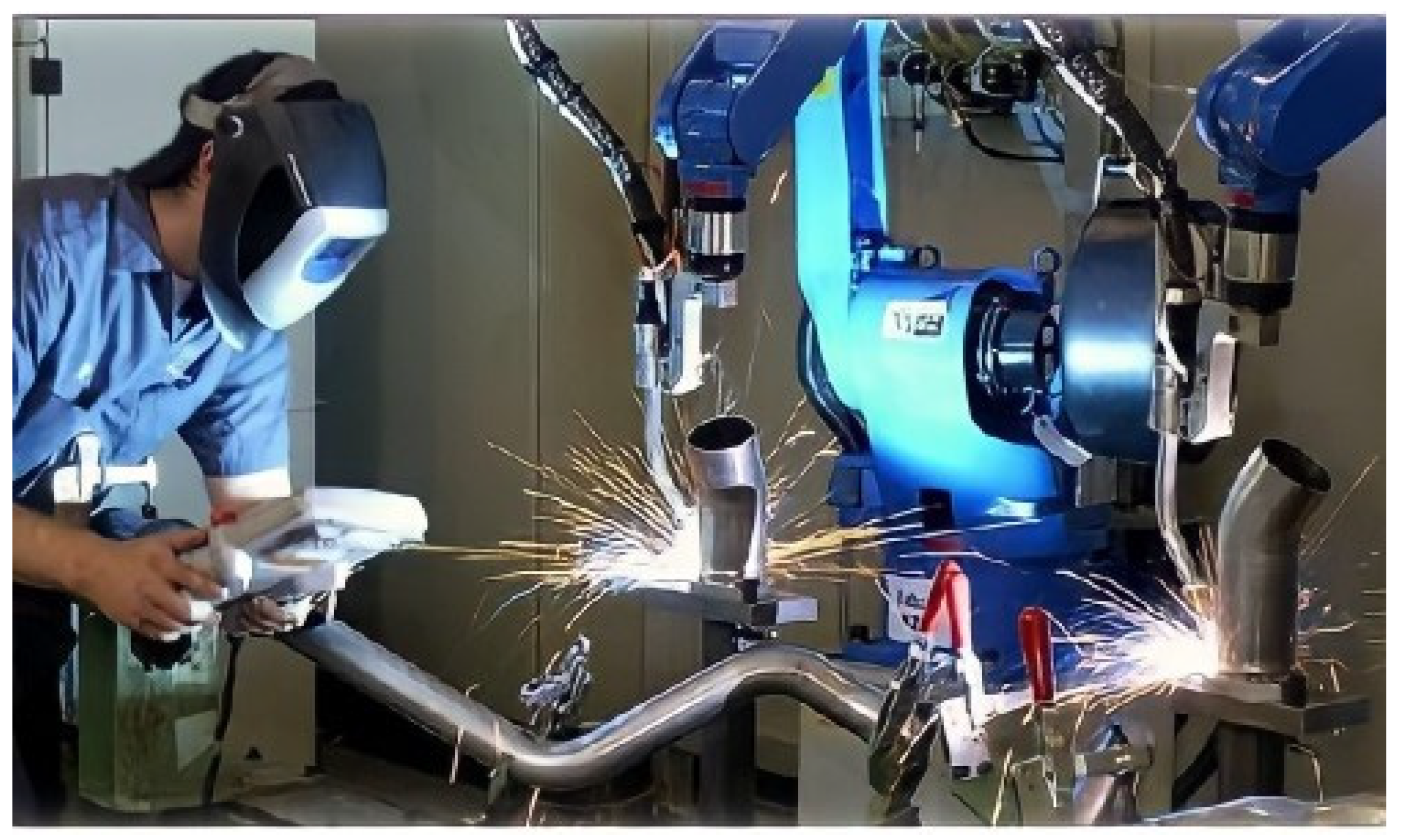
Equipment construction can include several large welding lines, especially with the use of multiple robots. The process is quite simple normally, there are positioners to be able to rotate the pieces to be welded, and then this operation is repeated. The movements and positions of the different robots are planned to avoid collisions. There are two methodologies to follow to solve this problem. The first is a function that predicts the robots stopping and their movement stops before the collision. The second way is to perform multi-layer welding on a single weld line with several robots. The robot performs multi-layer welding of a weld line together with another robot, which eliminates waiting time and significantly reduces the overall welding time. An example of a mechanical structure of an industrial robot is composed of two main parts, as shown in
Figure 1.
An example of a robotic welding system tool is shown in
Figure 2.
In the construction of steel equipment, there are different welding processes, and the choice between them mainly depends on efficiency. A key feature that must be considered is weldability. Therefore, it is essential to observe the effects of welding parameters on the weldability of materials during the arc welding process. Mild steel is the most common steel and provides acceptable material properties for many applications. The metals used in different commercial applications, such as aluminum, copper, stainless steel, and carbon steel, can be joined by this type of process by choosing the appropriate electrode and shielding gas, as well as the different welding conditions [
2]. Variations in power supplies and shielding gases, as well as electrodes, can cause different variations in the welding process, for this reason, it is necessary to choose the appropriate welding parameters [
3]. The metal to add to the parts is provided by a roller that allows a continuous electric arc [
4]. The greater the arc length, the greater the electromagnetic effects. Due to its importance, some researchers have studied the electromagnetic effects of welding processes [
4,
5,
6,
7].
2.2. Collaborative robots
Cobots can work without the need for peripheral protection, and their workspace can be more easily monetized. They can also be easily reprogrammed, even by workers without robotics programming knowledge [
15,
22]. In 2008, the company Universal Robotics or Cobot called UR5 [
16], and large robotics companies began to invest in the development of Cobots, in addition, there is already a very demanding set of security measures, namely ISO 10218 1, 10218 2 [
24]. It is guaranteed that if the operator’s safety distance is less than the Cobot distance, it will not work, in addition, the equipment will monitor the distance and reduce speed until it stops. The ISO/TS 15066:2016 standard defines good practices in collaborative environments. According to Muller et al. [
19], Cobots and operators can coexist, that is, when both work in the same environment but tend not to interact, or at different times of cooperation between them when both simultaneously perform tasks in the same space or different tasks. These systems allow for an increase in the quality of the products, and an improvement in the working conditions of the operators [
18,
19]. In this context, it is worth mentioning SMEs, due to the difficulty they have in automating their production processes using traditional industrial robots, in terms of space availability and investment [
23], as well as companies in sectors characterized by mass production [
20].
2.3. A prototype developed for the industrial environment
The developed prototype serves to implement an automated arc welding solution using Cobots. The prototype corresponds to the development of a cell composed of a Cobot. The main motivation for the company to develop this solution was the shortage of specialized labor, among other factors, repetitive tasks, and a high level of precision and concentration, which is sometimes inappropriate from an ergonomic point of view, presents high repeatability and movements that are quite complex and difficult for human beings to perform.
The preparation of the work in the positioning of the parts and the execution of the weld is a collaborative process between the operator and the Cobot, thus, cooperation becomes the key to a solution with much higher added value, allowing very low space occupation and high flexibility in the workplace.
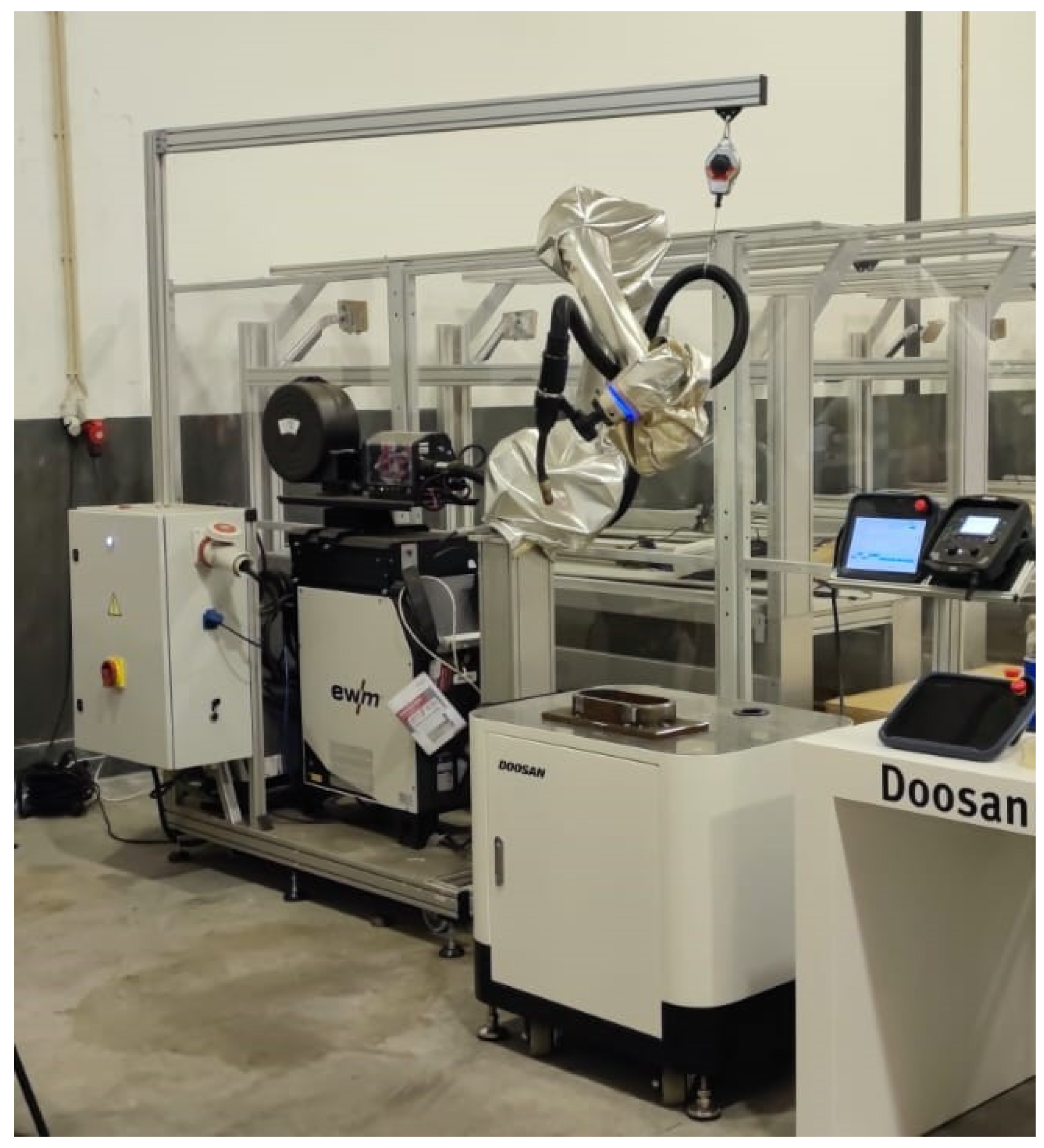
The prototype developed is a workstation that can be easily moved from one workstation to another. The industrial prototype involves the development of a collaborative robotic solution that includes a Doosan M0617 collaborative robot due to its large workspace and reach of 1700mm. As it is a welding solution for handling a welding torch with a load capacity of up to 6 kg, it is sufficient for the requirements of this work. The Cobot and the welding machine are mounted on a structure with wheels, and the parts to be produced are placed next to the Cobot on a table as shown in
Figure 3.
3. Results
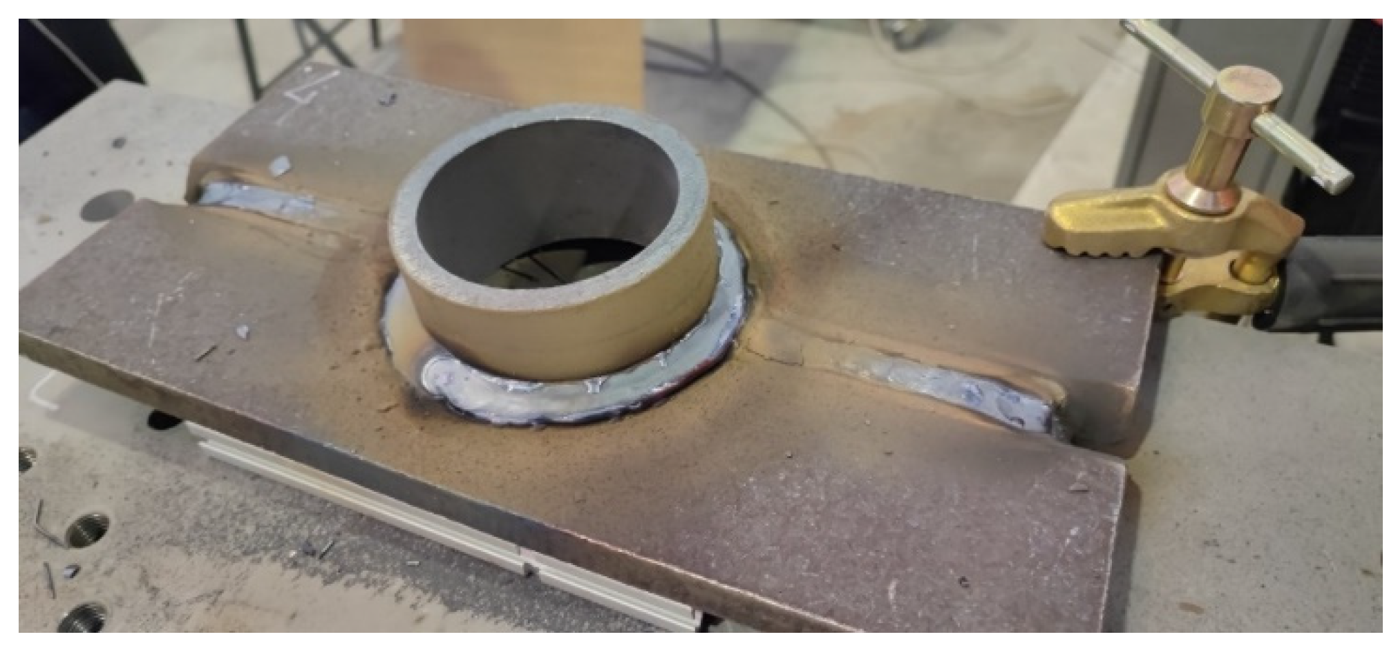
On the production line, the customer has several equivalent workstations, each with a specialized technician, in addition to having a more common portfolio of parts and having many different references and many small runs, this means that there are repetitions of tasks, and there are equivalent parts for production, which allows frequent setups, as shown in
Figure 4.
In the tested examples, two types of shielding gases were used: a mixture of 80% Argon + 20% CO2 and another of 92% Argon + 8% CO2 to provide a protective atmosphere, so that contamination between oxygen and nitrogen is avoided. The gas flow rate used was 12 l/min, and the electrical energy provided by the generator for fusion between the wire and the piece to be welded was controlled to reach a point chosen by the welder. stability of the electric arc, so that the length of the electric arc and the distance between the electrode and the workpiece were as short as possible to allow the best control. In this application, an electric arc of 5 mm in length was used. To maintain a continuous and regular melting zone, a welding speed close to 30 and 35 cm/min was considered, which is chosen according to the current intensity (A) and the welding voltage (V). The average heat input used was approximately 25 kJ/mm, for a wire diameter of 1.4 mm, and the wire feed speed was 10 m/min. Finally, we control the distance of 10 mm between the nozzle and the surface of the workpiece.
The manual procedure of the welding process presupposes the study of the manufacturing dossier of each piece. In manual manufacturing, the number of parts is indicated in the production order, and there are hundreds of different types of parts, all made of steel and usually of large dimensions. Due to their size, parts need large profile/section weld seams. Depending on the requirements, this type of weld bead is obtained using various multi-pass types of overlaps for each type of process, as shown in
Table 1.
The project requirements are based on the production dossiers and the customer’s welding technical sheets so that the welding operation is carried out automatically, that is, to automate the main process, knowing that based on the system requirements, it must be able to register complete welding programs, that is, programs concerning parts and with welding paths and parameters to be used in the welding process, as shown in
Table 2.
The complementary and auxiliary processes continue to be performed manually, but the ease of programming the paths, and learning from the welding geometry of the parts, is due to the high number of references. Each part reference and associated manufacturing requirements include the following characteristics, as shown in
Table 3.
The program that performs the welding is integrated with the Doosan controller (firmware v2.9) and contains the following features for welding relevant to the case, settings, and communication of variables with the welding machine, such as at the beginning of the welding process as well as the selection of the welding program. The possibility of previously configured bead formats: such as linear, straight, circular, arcs, trapezoidal, zig-zag, waves, and sinusoidal. Also, to meet the need for a large section of beads, it is necessary to perform multi-pass welding, that is, overlapping weld beads in the same joint to increase the total section. For this, a database is needed with the information of each passage, allowing automatic navigation between passages during production, as shown in
Table 4.
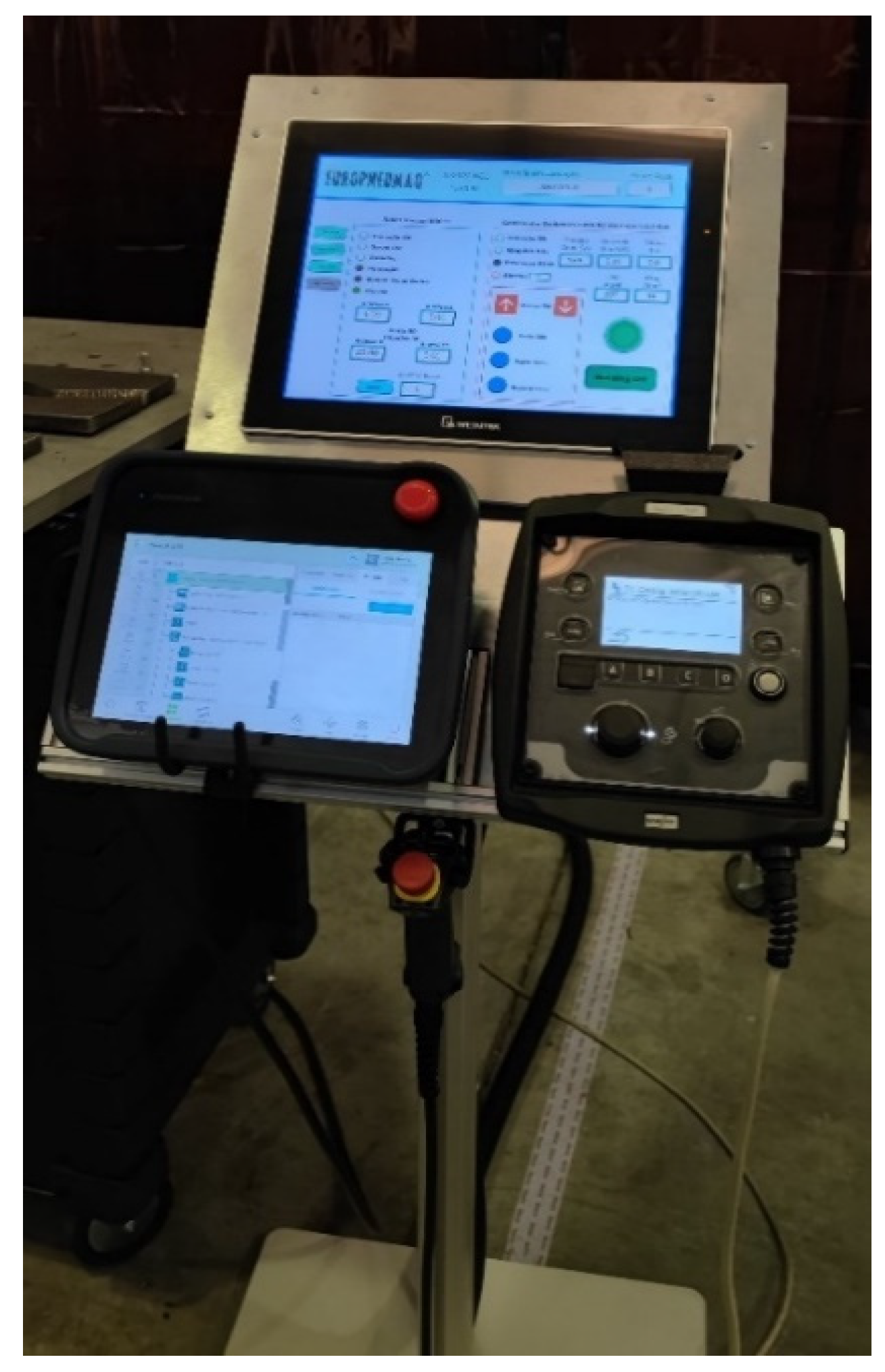
The complementary process will continue to be executed by the operator while the main processes and auxiliary processes will be executed by the robot, and the system assumes two different user profiles, operator, and specialized welding technician. Due to the welding know-how, specific requirements for each part, and the many parts, a tight system is not suitable for this purpose. Thus, the customer must be able to program or configure the system according to his needs, as shown in
Figure 5.
For the multiple pass revenues, the specialized welding technician develops the specific programming and configuration for each type of welding joint, and in each recipe, a set of data is stored that can be used by any program. The main objective of multiple-pass recipes is to explore the repeatability potential; that is, each type of joint with certain characteristics, namely the type of material, normally has the same welding parameters and depends on the multiple passes. Thus, this automated multi-pass allows removing tasks without added value during the production process.
In free actuation and automatic stitch adjustment, the operator, in the first instance, must develop the programs referring to each part reference, as shown in
Figure 6. For this, it uses a very friendly and intuitive programming environment, Task Builder and Free Drive (Cockpit), both native to Doosan equipment.
The presented solution also includes an automatic correction of points about the two important angles for the multi-pass: theta (θ) and gamma (γ).
In this solution, it is enough to “teach” the points referring to the first pass of the piece.
For free-drive and automatic stitch adjustment, the operator, in the first instance, will have to develop the programs referring to each part reference as shown in
Figure 6. For this, it uses the user-friendly and intuitive programming environment, the Task Builder, and the Free drive (Cockpit), both native to Doosan. The solution also includes an automatic correction of points concerning the two important angles for the multi-pass: theta (
θ) and gamma (
γ). In this solution, it is only necessary to “teach” the points referring to the first pass of the part.
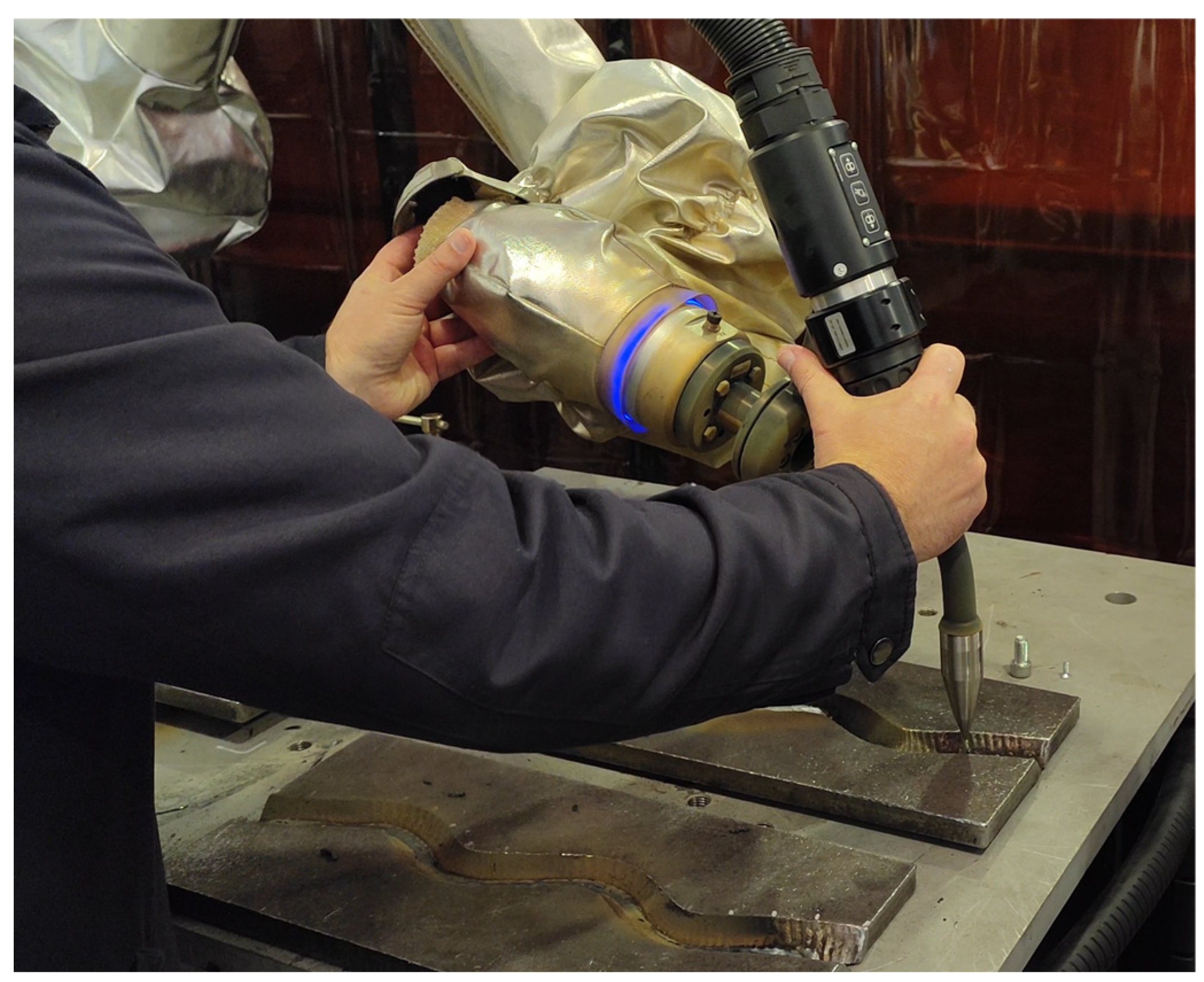
Finally, the production of the series of parts is carried out collaboratively with the system, that is, it is necessary to position the parts of the operator and execute the weld beads according to the programs and recipes, to be carried out by Cobot, as shown in
Figure 7.
4. Discussion
The development of the proposed solution allows for easy interaction with technicians in addition to reducing quality defects and production costs. Comparing the operating speeds of industrial robots and collaborative robots, in which industrial robots have a great advantage in operating speed, but as this type of equipment requires interaction with specialized technicians, it appears that it is advantageous to use more intuitive and easy-to-use systems, especially for small and medium-sized companies, in which the operator can easily create in detail all the dimensions and movements to be carried out, as well as simply change the welding parameters. In this way, it allows to increase productivity and improve the quality of their work, in addition, the worker is not replaced by the equipment, as well as he intends to continuously improve the work he is performing.
5. Conclusions
The use of technology can help companies achieve greater productivity, competitiveness, and quality, as well as reduce costs and time in their manufacturing process, but before adding new equipment, it is necessary to know how to maximize the return on investment. In our understanding, the path to innovation lies in the development of dedicated software, which allows for interesting solutions because, on the one hand, it simplifies the use of the resources of the acquired technologies, hides the more complex details, and allows the system to be more flexible to increase the profitability of the purchased equipment.
Author Contributions
For research articles with several authors, a short paragraph specifying their individual contributions must be provided. The following statements should be used “Conceptualization, Ferreira; methodology, Ferreira; software, Ferreira; validation, Ferreira; formal analysis, Ferreira; investigation, Ferreira; resources, Ferreira; data curation, Ferreira; writing—original draft preparation, Ferreira; writing—review and editing, Ferreira; visualization, Ferreira; supervision, Ferreira; project administration, Ferreira.;. All authors have read and agreed to the published version of the manuscript.” Please turn to the CRediT taxonomy for the term explanation. Authorship must be limited to those who have contributed substantially to the work reported.
Funding
This research received no external funding.
Data Availability Statement
In this section, please provide details regarding where data supporting reported results can be found, including links to publicly archived datasets analyzed or generated during the study. Please refer to the suggested Data Availability Statements in the section “MDPI Research Data Policies” at
https://www.mdpi.com/ethics. You might choose to exclude this statement if the study did not report any data.
Acknowledgments
In this section, you can acknowledge any support given which is not covered by the author’s contribution or funding sections. This may include administrative and technical support, or donations in kind (e.g., materials used for experiments).
Conflicts of Interest
Declare conflicts of interest or state “The authors declare no conflict of interest.” Authors must identify and declare any personal circumstances or interests that may be perceived as inappropriately influencing the representation or interpretation of reported research results. Any role of the funders in the design of the study; in the collection, analysis, or interpretation of data; in the writing of the manuscript, or in the decision to publish the results must be declared in this section. If there is no role, please state “The funders had no role in the design of the study; in the collection, analyses, or interpretation of data; in the writing of the manuscript, or in the decision to publish the results”.
References
- H. B. Cary, (1994). Modern Welding Technology, Third Edition, Regents/Prentice Hall Book, Company, Inc., Upper Saddle River, New Jersey.
- N. S. Seo, (2002). Modern Manufacturing Processes,” Dongmyungsa, Korea.
- P. F. Ostwald, and J. Munoz, (1997). Manufacturing Processes and Systems,” John Wiley and Sons, Inc., New York.
- S. Kalpakjian, (1992). Manufacturing Engineering and Technology,” Addison Wesley Publishing Company, Inc., Reading, MA.
- J. J. Craig, (1989). Introduction to Robotics, Mechanics, and Control,” Addison Wesley Publishing Company, Inc., Reading, MA.
- K. S. Fu, “Robotics, (1987). McGraw-Hill International Book Company, Inc., New York.
- Richardson RW, (1986). Robotic Weld Joint Tracking Systems - Theory and Implementation Methods, Welding Journal, Nov.
- Pires, JN, and Loureiro, Altino et al., (2002). Object-Oriented and Distributed Software Applied to Industrial Robotic Welding, Industrial Robot, An International Journal, MCB University Press, March. [CrossRef]
- Pires, JN, and Loureiro, A et al., (2003). Welding Robots, IEEE Robotics, and Automation Magazine.
- Pires, JN, (2005). Complete Robotic Inspection Line using PC based Control, Supervision, and Parameterization Software”, Elsevier and IFAC Journal Robotics and Computer Integrated Manufacturing, Vol. 21, No1.
- Pires, JN, (2005). Complete Robotic Inspection Line using PC-based Control, Supervision, and Parameterization Software, Elsevier and IFAC Journal Robotics and Computer Integrated Manufacturing, Vol. 21, No1. [CrossRef]
- Pires, JN, and Loureiro A et al., (2003). Welding Robots, IEEE Robotics, and Automation Magazine.
- Michalos, G. et al., (2014). ROBO-PARTNER: Seamless Human-Robot Cooperation for Intelligent, Flexible, and Safe Operations in the Assembly Factories of the Future. Procedia CIRP. [CrossRef]
- Peshkin, M.A.; Colgate, J.E.; Wannasuphoprasit, W.; Moore, C.A.; Gillespie, R.B.; Akella, P. Cobot architecture. IEEE Trans. Robot. Autom. 2001, 17, 377–390.
- Universal Robotics, Our history, (2018), https://www.universal-robotics.com/about-universal-robotics/our-history.
- Müller, R., Vette, M., Geenen, A., (2017) Skill-based dynamic task allocation in Human-Robotic-Cooperation with the example of welding application. Procedia Manuf., 11, 13–21. [CrossRef]
- Lasota, P.A.; Song, T.; Shah, J.A. A Survey of Methods for Safe Human-Robot Interaction; Now: Delft, Zuid-Holland, Netherlands, 2017; p. 1.
- Wang, W.; Li, R.; Chen, Y.; Diekel, Z.M.; Jia, Y. Facilitating, Human–Robot Collaborative Tasks by Teaching-Learning-Collaboration From Human Demonstrations. IEEE Trans. Autom. Sci. Eng. 2019, 16, 640–653.
- Eloise Matheson, Riccardo Minto, Emanuele G. G. Zampieri, Maurizio Faccio and Giulio Rosati, (2019), Human–Robotic Collaboration in Manufacturing Applications: A Review, Robotics 2019, 8, 100. [CrossRef]
- R. Muller, M. Vette, O. Mailahn, (2016), Process-oriented task assignment for assembly processes with human–robotics interaction, Proc. CIRP 44, 210–215. [CrossRef]
- Shirine El Zaatari, Mohamed Marei, Weidong Li, Zahid Usman, (2019), Cobot programming for collaborative industrial tasks: An overview, Robotics, and Autonomous Systems, Volume 116, Pages 162-180.
- L. Peternel, W. Kim, J. Babic, A. Ajoudani, (2017), Towards ergonomic control of human–robotics co-manipulation and handover, in 2017 IEEE-RAS 17th International Conference on Humanoid Robotics (Humanoids), IEEE.
- European Commission, (2018), Periodic Reporting for period 1 - colrobotics (collaborative robotics for assembly and kitting in smart manufacturing), Tech. Rep.
- Pentikainen, T et al., (2016). How to make collaborative robot programming easier. Teknisk- naturvetenskaplig fakultet UTH-enheten Platbrood, F e Görnemann.
- Platbrood, F e Görnemann, O, (2018). Safe robotics – A segurança em sistema.
- Ciszak, O.; Juszkiewicz, J.; Suszyński, M. Programming of Industrial Robots Using the Recognition of Geometric Signs in Flexible Welding Process. Symmetry 2020, 12, 1429.
|
Disclaimer/Publisher’s Note: The statements, opinions and data contained in all publications are solely those of the individual author(s) and contributor(s) and not of MDPI and/or the editor(s). MDPI and/or the editor(s) disclaim responsibility for any injury to people or property resulting from any ideas, methods, instructions or products referred to in the content. |
© 2023 by the authors. Licensee MDPI, Basel, Switzerland. This article is an open access article distributed under the terms and conditions of the Creative Commons Attribution (CC BY) license (http://creativecommons.org/licenses/by/4.0/).
