1. Introduction
Industrial systems have undergone four stages of revolution, starting from the mechanical phase in the end of 18th century to the first production lines in the beginning of the 20th century. The third stage from 1970 and onward introduced the first electronic devices as the Programmable Logic Controllers (PLCs) for automating parts of the manufacturing process. Over the latest years, the systems have become fully automated and gradually require no human intervention as they begin to operate autonomously. This introduced a new area in manufacturing called Industry 4.0 allowing significant improvements in performance and decision-making, which makes production lines more efficient [
1].
A significant drawback of automation though is that it increases the system’s complexity as well as its heterogeneity. This increases the development and maintenance effort for control engineers. Moreover, another challenge for industrial manufacturers lies on the inability of traditional TCP/IP protocols to satisfy deterministic, real-time demands of industrial applications [
2]. On top of that, the risks in safety and reliability of the industrial system are ever-growing [
3], especially when considering that industrial machinery is taking decisions autonomously based on input from its external environment.
To tackle these challenges, device vendors have introduced proprietary Real-Time Ethernet technologies to allow real-time communication and determinism characteristics. Such characteristics allow industrial applications to meet their tight deadlines as opposed to the traditional Ethernet. Moreover, Real-Time Ethernet technologies provide high degree of parameterization in the control devices, thus making them reasonably intelligent. Towards the direction of Real-Time Ethernet technologies each vendor started to define different communication profiles for each application domain, which established a heterogeneity not only in terms of protocols, but also in operating systems and drivers for the proprietary hardware that is specific by each vendor [
3].
The presence of multiple vendor solutions, made industrial plant manufacturers hesitant for the adoption of Real-Time Ethernet, due to the time and effort needed for the integrating the solutions into their legacy production lines. Instead many production lines nowadays employ serial or electrical connections for the communication within the factory [
4]. A solution towards this direction is to provide standardized protocols and profiles that will be used by all the industrial device vendors to build and configure their devices, such as Ethernet Powerlink [
5,
6] and CANopen [
7]. Nevertheless, even with the presence of standardization, the challenge of developing rapidly reliable applications is still present for industrial plant manufacturers.
Another important challenge for industrial architectures towards the Industry 4.0 area is the cyber-security, indicating the ability of an infrastructure to remain resilient against cyber-attacks. Cyber-security is strongly connected to safety and reliability requirements of a system [
8]. Towards this direction, many industrial platforms started to include security mechanisms, as the Netfilter firewall that uses the iptables rules and policies [
9].
However, the presence of these mechanisms does not increase the security level of industrial architectures. This is due to the fact that they are either 1) not used due to implementation effort that is required or 2) use simplified rules and policies for their firewalls that allow all inbound as well as outbound communications [
10]. The use of simplified rules is explained by the desire of industrial manufacturers to not cause any degradation on the industrial process. Nevertheless, Ethernet Powerlink networks require a high-level of determinism, which is at risk if traditional Ethernet messages are transmitted to the Ethernet Powerlink network. The reasoning is that such messages may introduce conflicts or extended processing delays.
In this paper, we propose a novel method allowing to automate the generation of verified executable code based on a high-level programming models for industrial applications. Apart from the functional code, our method provides the additive ability of defining firewall rules for each process to protected the Ethernet Powerlink network against unauthorized access.
The method is demonstrated through case-study on a safety-critical system that allows fault-tolerance for power production plants. Specifically, the generated code is deployed in Programmable Logic Controllers (PLCs) [
4] that control the power generator of a Hydroelectric Power Plant, used by the Public Power Corporation in Greece to produce electricity. The case-study illustrates the reliability of the power generator under both normal as well as error-prone operating conditions. Specifically, this article has the following concrete contributions:
Definition of a high-level programming model for industrial applications
Development of reusable code templates for automated generation of executable code for industrial applications
Implementation of mapping procedures and deployment configuration for industrial applications on Real-Time Ethernet architectures using Ethernet Powerlink
Specification of firewall policies to produce rules that ensure cyber-resilience for the industrial architecture
Application of the method to a Hydroelectric Power Plant of the Public Power Corporation
The rest of the article is organized as follows.
Section 2 provides a brief introduction to industrial automation networks, such as Ethernet Powerlink as well as the programming model that is used for modeling networked embedded applications.
Section 3 demonstrates the proposed method by applying the programming model on industrial applications and
Section 4 evaluate the demonstrated method on a safety-critical system of an industrial plant. Then,
Section 5 presents the main benefits and limitations of the proposed method as well as compares it with similar work. Finally,
Section 6 provides conclusions and perspectives for future work.
2. Background
2.1. Industrial automation networks
In this section we provide a brief introduction to Real-Time Ethernet protocols that are used in the scope of our method.
2.1.1. Ethernet Powerlink (EPL)
EPL [
6] is a commercial protocol for industrial automation systems based on the Fast Ethernet IEEE 802.3. One of protocol’s major advantages is that it can operate with either the use of Ethernet switches or hubs, depending on the temporal constraints of the application. To overcome the effect of collisions occurring in standard Ethernet systems, EPL uses a TDMA technique (deployed in the data link layer), which is based on a mixed polling and time slicing mechanism, called Slot Communication Network Management (SCNM) (
Figure 1). This technique uses a special node, referred as Managing Node (MN), to grant the slave devices, referred as Controlled Nodes (CN’s), access to the medium only when they are polled. The use of SCNM hampers the direct deployment of standard Ethernet devices in the network, as they would corrupt the access mechanism. To overcome this limitation dedicated gateway are connected to control the communication traffic of standard Ethernet devices. The supported topologies in EPL are the line and star topology.
EPL supports periodic and event-based data exchange during a cyclic period of fixed duration. This period is divided in four phases, the starting, the isochronous, the asynchronous and the idle phase. The synchronized transition between phases is done through broadcast frames initiated by the MN device. More specifically, the reception of the Start of Cycle (
SoC) frame by the slave devices ends the starting phase and accordingly begins the isochronous (cyclic) phase. During this phase the MN polls progressively every CN through a
PReq unicast frame, in order to receive their data responses through the subsequent
PRes frames. The
PRes frames are also broadcasted, in order to facilitate data distribution amongst all the remaining nodes. Having polled all the CN devices in the EPL network, the MN broadcasts the Start of Asynchronous (
SoA) frame, to indicate the beginning of the asynchronous period. This period allows a single asynchronous transaction (
Send in
Figure 1) to be performed. This transaction might be an asynchronous EPL data frame (
ASnd frame), detection of active stations (
IdentRequest frame), or even a standard Ethernet data frame. All the asynchronous transactions are enqueued in the MN, in order to be transmitted according to their priority. As the asynchronous period is used for the exchange of large frames, the EPL cycle includes the idle phase to ensure that the ongoing transaction has ended.
2.1.2. Integration with CANopen communication profiles
Even though Real-Time Ethernet technologies are widely used for industrial automation systems, application development is still challenging, due to their low level complexity as well as their high expertise needed for their configuration. Therefore, a higher layer of abstraction is required, which is typically found in application-layer protocols. An increasingly popular application-layer fieldbus protocol is CANopen [
7], as it provides a vast variety of communication mechanisms, such as time or event-driven, synchronous or asynchronous as well as additional support for time synchronization and network management. Furthermore, it offers a high-degree of configuration flexibility, requires limited resources and has therefore been deployed on many existing embedded devices.
EPL is fully integrated with the CANopen protocol as well as its communication and device profiles [
7]. As a result of the integration, CANopen’s objects are encapsulated into lower-layer EPL frames. Initially, during the isochronous phase of the EPL cycle (
Figure 1), data relevant to the application are stored and exchanged through Process Data Objects (PDOs). To this regard, the MN sends a real-time data transfer frame, or Transfer Process Data Object (TPDO) as it is referred in CANopen specifications, to each CN via a PReq frame. In turn, each CN stores the data in one or more RPDOs and responds with a TPDO encapsulated in a PRes frame. Moreover, in the asynchronous phase configuration data are exchanged through Service Data Objects (SDOs), used for the transmission of configuration data in CANopen. SDOs are encapsulated in ASnd frames. EPL also uses the Object Dictionary (OD) of CANopen as a node database for storing all the network-accessible data. It may also contain a maximum of 65536 entries as well distinguished in the communication, manufacturer and device specific categories. The OD entries are described by the generic description of a device type, or so-called in CANopen XML Device Description (XDD), as well as the configuration for a specific device, or so-called XML Device Configuration (XDC), file formats.
Even though the CANopen communication profile is fully integrated in EPL, there are also minor differences between them as with the SDO channels, which are defined and configured during initialization in CANopen, but instead EPL allows a dynamical configuration of these channels. Another difference lies on the transmission of unconfirmed segment frames during the segmented data transfer in EPL, whereas CANopen segments are always confirmed [
7]. A method for confirming the transmission when large amounts of configuration data need to be exchanged is through the use of multiple expedited SDO transfers.
2.1.3. Application development with openPOWERLINK
To facilitate application development with Ethernet Powerlink (EPL) a tool was developed, named openPOWERLINK [
11]. openPOWERLINK is an open source (BSD Licence) Real-Time Ethernet stack provided by SYSTEC electronic
1. openPOWERLINK is developed using a layered approach, which segments the system in a hierarchical way, namely the user and the kernel part. The former implements the application layer of the EPL protocol and provides an API for the development of EPL applications. It contains an implementation for the OD, as well as the PDO, SDO, Error Handler and Event Handling modules. The latter implements the Data Link Layer (DLL) of the EPL protocol and the necessary drivers to communicate with the hardware. It also contains an Event Handling module as well as implementations for an Ethernet and a time-critical driver (for the time slicing mechanism). The Event Handling module is responsible for delivering events, which are related to object dictionary accesses, completion of SDO transfers, configuration and stack errors etc. The two parts interact with each other by message passing through the Communication Abstraction Layer (CAL). All the processes defined above the CAL have a high-priority in the stack, whereas the ones below have a low-priority.
The overall architecture of the openPOWERLINK stack is illustrated in
Figure 2. Following the integration with CANopen profiles, openPOWERLINK also supports Management (NMT) functionalities related to CANopen [
12], to allow operational state changes for each node of the EPL architecture. Operational states in openPOWERLINK are managed through the NMT module that is included in each Managing Node. With this module the Managing Node can manage the NMT state machine of the Controlled Nodes. Specifically, the Managing Node can change the state of Controlled Nodes according to four options: PreOperational1, PreOperational2, ReadyToOperate and Operational. In the PreOperational1 state all the modules are stopped, the PreOperational2 allows the functionality all the modules except from the PDO and the ReadyToOperate is a transitional state where the PDO module before moving to the Operational state.
Lessons learned from our usage of openPOWERLINK for the development of functional industrial applications included the following sequential steps:
The MN should detect and access the connected CNs in the EPL network through an Ident Request
The Object Dictionary entries in the CNs are initialized by dedicated SDO frames in the asynchronous phase of the EPL cycle
The process variables of the EPL Application layer should be linked with entries of the OD module for each node (MN or CN). Once linked, a modification of a process variable will automatically signal the API layer to update the dedicated entry in the node’s OD.
Implementation of the callback between the Communication Abstraction Layer (CAL) and the Data Link Layer for the kernel part.
Implementation of the callback between the EPL Application and the API layer for the user part.
Despite the presence of the openPOWERLINK stack and the presented application development steps, the development of industrial applications using openPOWERLINK requires extensive knowledge of the API. Additionally, it may often be time-consuming, due to the asynchronous callbacks that should be considered for data handling as well as the need for proper device configuration. Specifically, the main challenges (by priority level) are summarized below:
Separation of functionalities between the EPL nodes. The developer should be able clarify and implement a different behavior for each EPL node, according to the type of EPL application. As an example in a sense-compute-control application the MN node is not only used for polling, but the CN’s may often require dedicated data from it, in order to perform actuation. This is handled in the EPL cycle by supporting transmission capabilities to the MN node using proper configuration. Therefore, the developer should be able clarify and implement a different behavior for each EPL node.
Mapping of application-specific functionality to the Object Dictionary entries. Once a clear functionality separation is defined, specific entries to the Object Dictionary should be assigned for handling the network configuration as well as the exchange of time critical or asynchronous data in the application. This task should be done in respect to the CANopen profile and thus requires high expertise, in order to define the correct data encoding and object linking and may be time consuming if the application’s behavior is complex.
Selection of the EPL configuration parameters. EPL applications are characterized by strict timing constraints. Therefore the selection of parameters, such as the cycle duration, the timeout for acquiring the polling responses, the tolerance timeout in the CN’s for receiving the SoC frame and the maximum transmitted data during the asynchronous phase, determines to a large extent the EPL application functionality. The selection of these parameters also depends on the characteristics of resource-constrained devices (e.g., computational platforms), which are chosen in the underlying hardware architecture.
To tackle these challenges in
Section 3 we illustrate a method for reducing the engineering time and effort for the development of industrial automation application. The method is based on the Pragmatic Programming Model (PPM) that is described in the following section.
2.2. PPM: A programming model for networked embedded applications
The Pragmatic Programming Model (PPM) [
13] is a description language developed to provide a simple and convenient way for describing highly-parallel applications expressed as a process network, which involves communication between different processes. A process network is a directed graph, where the nodes represent the processes and the directed edges represent the communication channels between them. The language has been inspired by DOL (Distributed Operation Layer) [
14], which is a framework devoted to the specification as well as the analysis of mixed software/hardware systems by providing a Kahn Process Network (KPN) model of the application. Even though DOL provides a fine grained programming model for the application software, it cannot be extended in networked embedded systems due to three main reasons. Initially, it uses as a basic representation the KPN programming model, in which each process can only communicate through the use of FIFO queues. Writing/reading to/from the FIFO queues is non-blocking since they are assumed to be as large as needed. However, networked embedded systems may use other ways to support communication between different devices apart from FIFO queues, as for example through the use of shared memories. Moreover, as we previously mentioned each device has limitations on its available storage memory and therefore the size of every FIFO queue should be bounded. Secondly, DOL allows restricted communication primitives, which are allowing synchronous communication between the application-level processes. Nevertheless, networked embedded systems are mainly using asynchronous communication, such as event-triggered transmission, and dedicated techniques as asynchronous callbacks to perform data exchange. Finally, since DOL is used to describe multiprocessor systems, specific API primitives of the hardware (HW) architecture in networked embedded systems are also not supported. For all these reasons, we have defined the a new framework (PPM), which addresses these limitations in a systematic way and provides additional characteristics to the description of the application software (detailed in the following paragraph).
In PPM, application software is defined by using a process network model. It consists of a set of deterministic, sequential processes communicating asynchronously through shared objects, such as FIFOs, shared memories and mutexed locations. The process network structure in PPM is described by using XML specifications and the process behavior is described using structured C code, with well defined communication primitives.
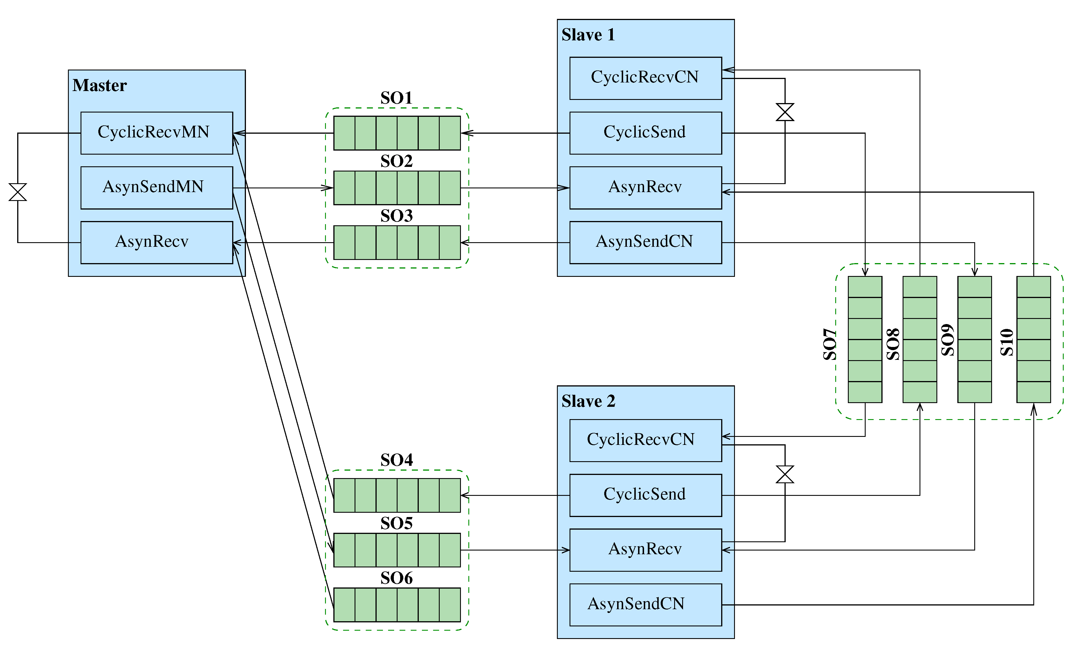
Figure 3 presents an example of a PPM application for industrial systems.
The behavior of each PPM process is described in C language and has a particular structure, which is presented in Algorithm 1. This algorithm defines three abstract functions, which are implemented based on the application logic and requirements. Each function operates on the process state. Specifically, the
init() function initializes the process data and is followed by an endless loop calling the
fire() function. In this function the process can communicate read and write primitives for respectively sending and receiving data to shared objects. A read operation reads data from an input port, and a write operation writes data to an output port. Additionally, the
fire() function may invoke a detach primitive in order to terminate the execution of the process. Before termination the
deinit() function is executed, in order to deallocate the memory that is reserved for the process thread as well as for the defined variables or the processed data.
|
Algorithm 1 PPM Process behavior |
- 1:
procedure <procName> init(<procName> process *p) - 2:
initialize process data - 3:
end procedure - 4:
while (true) - 5:
- 6:
procedure <procName> (<procName> process *p) - 7:
<sharedObjectTyperead(buffer,INPUT,size) - 8:
perform computation - 9:
<sharedObjectTypewrite(buffer,OUTPUT,size) - 10:
end procedure - 11:
end while - 12:
procedure <procName> (<procName> process *p) - 13:
deallocate process thread and data - 14:
end procedure |
2.3. Automated code generation from PPM models
The generated code from PPM consists of the functional code and the glue code. The functional code is generated from the application software in PPM consisting of processes and shared objects. In the case of networked embedded systems, processes are implemented as threads, and shared objects are implemented according to the underlying communication protocols. The implementation in C contains the thread local data and the routine implementing the specific thread functionality. The latter is a sequential program consisting of plain C used as a controller, wrapping the process C code described in PPM. The communication function calls are implemented by substituting the read and write primitives by read and write API calls on the respective communication protocol.
On the other hand, the glue code implements the deployment of the application to the resource-constrained platforms, i.e., allocation of threads to the devices (i.e., hardware platforms). The glue code is essentially obtained from the application deployment (i.e., mapping) PPM specification. Threads are created and allocated to network devices according to the process mapping, which also specifies configuration parameters for the underlying communication protocols. The glue code is linked with hardware architecture library to produce the binary executables for execution on the resource-constrained devices. The generated code is described in C language. Both functional and glue code are implemented using re-targetable template files and hardware specific files.
3. Applying PPM for industrial applications
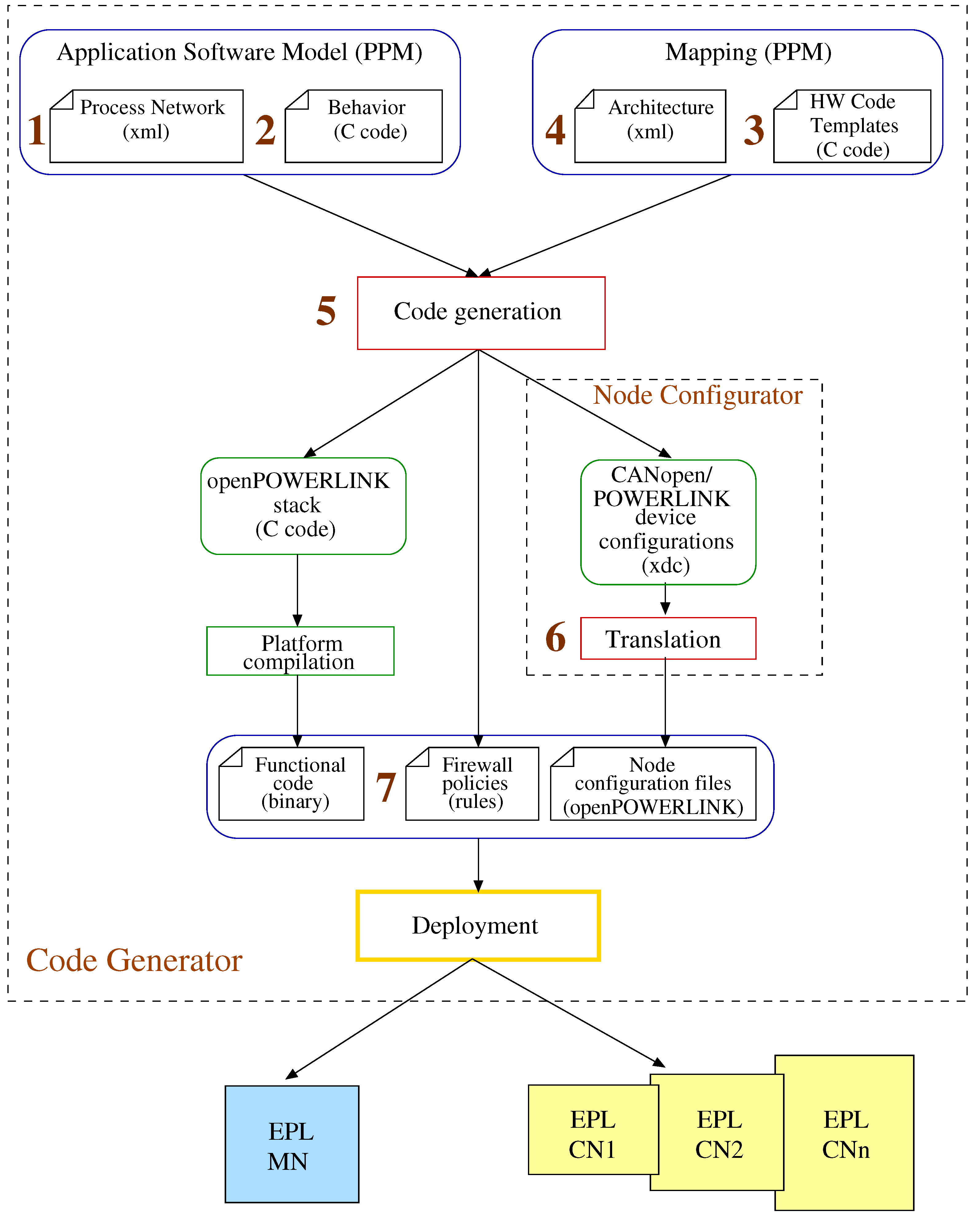
In this section we describe the method that is used to automate code generation from industrial programming models. The method (
Figure 4) aims in reducing the overall complexity in industrial application development using the openPOWERLINK stack. It requires as input the PPM model of the application software along with code templates for the application-specific behavior as well as the hardware platform. The latter includes application deployment in an EPL architecture and respective code templates for the implementation of CANopen’s primitives and communication mechanisms.
Overall, the method to generate executable code for industrial systems consists of the sequential steps. These steps concern artifacts (i.e., inputs and outputs) of the methods as well as tools that were developed to automate the process and are also marked in
Figure 4 to improve the reader’s comprehension.
Describing the application behavior in PPM processes. This step aims at identyfying the PPM processes that characterize the application and including them in the PPM XML process network description (
Section 3.1). The number of application processes for the PPM network is proportional to the functionalities that the application should implement. Each process that is selected in this step should implement atomic and have no overlap with the others. Such processes are the CyclicRecvMN and CyclicRecvCN of
Figure 3 implementing message reception in the EPL control loop process.
Development of code templates for the application behavior. The developed code templates model the application behavior in PPM and concern the user part of the openPOWERLINK stack. Hence, they describe the behavior as well as the interactions of each process in the application software with the API layer of the openPOWERLINK stack. The initial development is manual and conforms to the system requirements (
Section 3.2). The developed code templates though are modular and can be used afterwards for any application with similar requirements.
Linking application behavior with the openPOWERLINK libraries. The high-level behavior that belongs to the user part of the openPOWERLINK stack needs to be linked with the lower layers i.e., the CAL and kernel layers. These layers are added as libraries and do not require any development since they are already part of the openPOWERLINK stack. Moreover, they can be used by any hardware architecture that involves network communication through the EPL protocol. Linking is a sequential process where first the libraries are initialized according to the parameters of the Architecture XML specification. Secondly, the shared objects of the Application Software Model are replaced with the API primitives of openPOWERLINK as well as the code libraries implementing the lower layers of the stack. Finally, the processes of the Application Software Model are instantiated according to the Architecture XML specification.
Mapping of application processes in the EPL architecture. This step concerns the mapping of the processes in the EPL architecture as well as the proper distribution of the application processes to the underlying EPL architecture, that is described in the Architecture XML specification
Section 3.3. This specification also includes firewall rules described in Netfilter format. These rules are used to produce node configurations that ensure cyber-resilience in the EPL architecture (Step 7).
Code generation for Real-Time Ethernet architectures. The code in the flow is generated using a) the result of application behavior linking with the openPOWERLINK libraries in Step 3 as well as b) the mapping specification of Step 4. The procedure is described in
Section 3.4. The specific artifacts that are generated through this step are initially the functional code in C that is compiled in the chosen hardware platform to produce executable (i.e., binary) format for the Managing and Controlled Nodes. Second artifact are the firewall configuration files (in rules format) for the cyber-resilience of the EPL architecture. Final artifact are the node configuration files in XDC format, which are compatible with both CANopen and EPL.
Translation of the CANopen/EPL device configurations into openPOWERLINK configuration files. Since the content of the XDC configuration files cannot be interpreted directly by the openPOWERLINK stack, additional effort has to be done to translate them before the deployment of the generated code. To automate this step we have developed a node configuration tool (Appendix A) that handles this translation. Specifically, it parses the CANopen/EPL device configurations in order to create a) header files related to the object definitions, b) initial object configuration files as well as to provide object linking information to the API module of the stack. The resulting configuration files are provided to the OD module of the stack.
Cyber-resilience through firewall rules in EPL nodes. To generate firewall rules specific for the EPL architecture, our method uses abstract firewall specifications that are derived from the system requirements. Afterwards, through a semantic translation [
9] Netfilter configuration files are produced in rule format, that can be ported in all the EPL nodes of the architecture. This ensures protection against unauthorized access for the EPL system.
3.1. Modeling industrial application software in PPM
In this section we detail on the underlying effort, which is required to describe an industrial application into a network of communicating processes in PPM.
The processes of the PPM Application Software are encapsulated in process blocks according to their usage (
Figure 3). Industrial applications usually employ Master-Slave communication, hence two process blocks were identified, namely the Master and the Slave block. The processes of the PPM Application Model can either belong to the Master block, the Slave block or both. Those that belong to both blocks are mainly responsible for data reception during the asynchronous phase (
AsynRecv). Data reception may concern EPL frames (i.e., ASnd) or even non-EPL frames. The Master block contains processes for data reception in the EPL cycle (
CyclicRecvMN) as well as network management and device detection during the asynchronous phase (
AsynSendMaster). On the other hand, the Slave blocks (Slave 1 and Slave 2) contain processes for responding to polling requests (
CyclicSend), to identification requests (
AsynSendSlave) as well as additional processes for data reception in the EPL cycle (
CyclicRecvCN). Data exchange in the model is represented through shared objects (SO1, ..., S10) that represent FIFO queues (
Figure 3). The behavior of the
CyclicRecvCN process is different from the
CyclicRecvMN process of the Master block, in order to ensure the proper functionality of the EPL cycle.
The PPM Application Model is described in XML (
Figure 5). It consists of processes, shared objects and connections. For each process, we specify its name (e.g., process name=“CyclicRecvMN"), the names of the input and output (e.g., port name=“out") ports, the respective process type (e.g., process-class=“WhileFire") as well as the location of the source C code describing the process behavior (e.g., file=“CyclicRecvMN.h" or “CyclicRecvMN.c"). For each shared object we specify its name (e.g., shared-object name=“SO1"), its type (i.e object-class=“FIFO" or “MUTEX"), the maximum capacity of data (e.g., size=“4") and the names of the input (e.g., port name=“in") and output port (e.g., port name=“out"). Each process includes firewall rules that are defined using the tag
rule. Finally, we define the connections between the processes and the shared objects (e.g., port-ref node=“SO1" or “CyclicRecvMN") by specifying the input and output ports which contribute in each connection.
The resulting model of
Figure 3 and includes communication between application software processes through the shared objects of FIFO type. Moreover, additional shared objects of MUTEX type were used to enforce scheduling policies between the threads that are instantiated for the processes. An example in this scope are the process threads that are allocated for data reception, such as the threads for the
CyclicRecvMNand
AsynRecv processes.
3.2. Code templates for industrial architectures
The code templates require an initial manual development effort both at application as well as industrial architecture level. The application code templates contain the behavior of industrial applications according to their requirements, whereas the industrial architecture templates contain the interactions and communication mechanisms for the modules of the user part in the openPOWERLINK stack (
Figure 2). The user part is developed first as it concerns the configuration and interactions of each node in the industrial architecture. At a later stage the user part is combined with the lower-layers of the openPOWERLINK stack, such as the Communication Abstraction Layer (CAL) and the kernel part, which are included as code libraries in the XML specification of the industrial architecture. Once the initial development is finalized the code templates can be used and configured for automated code generation in any industrial application using the openPOWERLINK stack.
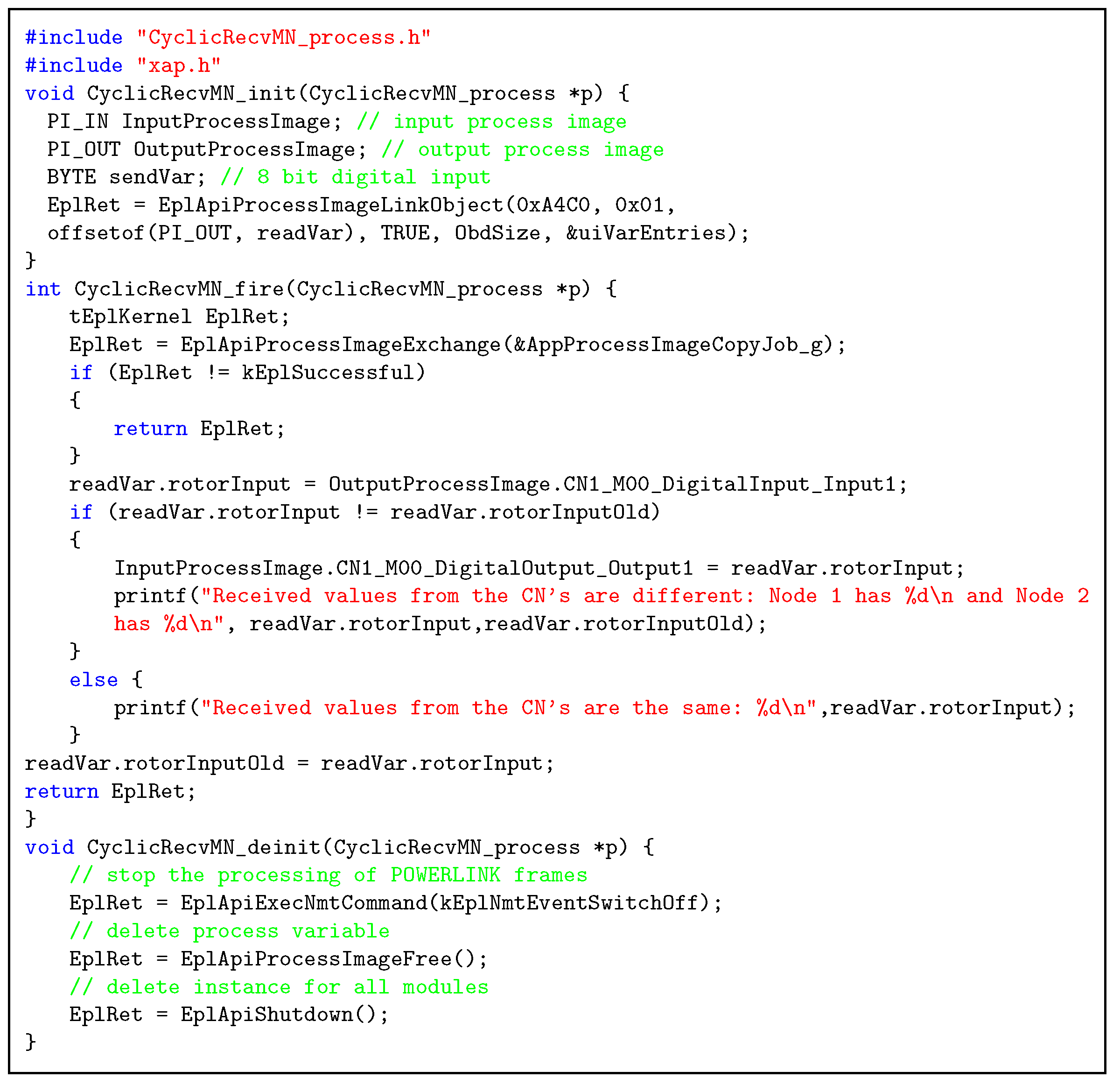
An example on the development of code templates for industrial applications in PPM is presented in
Figure 6, where we present the
CyclicRecvMN PPM process. This process is specified in
Figure 5 and uses the FIFO SO1 to receive data during the isochronous phase in EPL through the PRes frames. Moreover, it is implemented in the Master block of processes.
According to Algorithm 1, this process has three main functions (i.e., init, fire and deinit). The code for each function is following the structure of the openPOWERLINK applications. Examples of such applications are provided along with the openPOWERLINK stack source code
2.
Each function has a prefix of the process it belongs to i.e., CyclicRecvMN in
Figure 6. Concerning the behavior of each function, the
CyclicRecvMN_init function defines input (InputProcessImage) and and output (OutputProcessImage) process variables, which handle the transmission and reception of data between the EPL Application and the API layers of the openPOWERLINK stack respectively. As a further action, the process variables are linked with OD entries (lines 7-8). The cyclic behavior of the process is defined through the
CyclicRecvMN_fire function, which as defined in
Section 2 is a loop function that executed repeatedly. This function specifies the actions followed in the course of the EPL cycle, where the data through the PRes frames are received in the OutputProcessImage process variable (line 17). Then, they are manipulated according to the application-specific functionality and the outputs of the processing trigger dedicated actions, such as output to the screen (line 21) or dedicated actuators as for example LEDs. The
CyclicRecvMN_deinit function stops the EPL frame processing (line 29), deletes the process variables (line 33) as well as the instances for all the modules of the openPOWERLINK stack (line 35).
3.3. Deployment of industrial applications to the underlying architecture
The deployment of each industrial application to the EPL-based architecture is following the mapping specification in PPM of
Figure 4. The PPM mapping specifies how the processes and shared objects of the PPM Application Model are mapped to the hardware nodes of the EPL architecture.
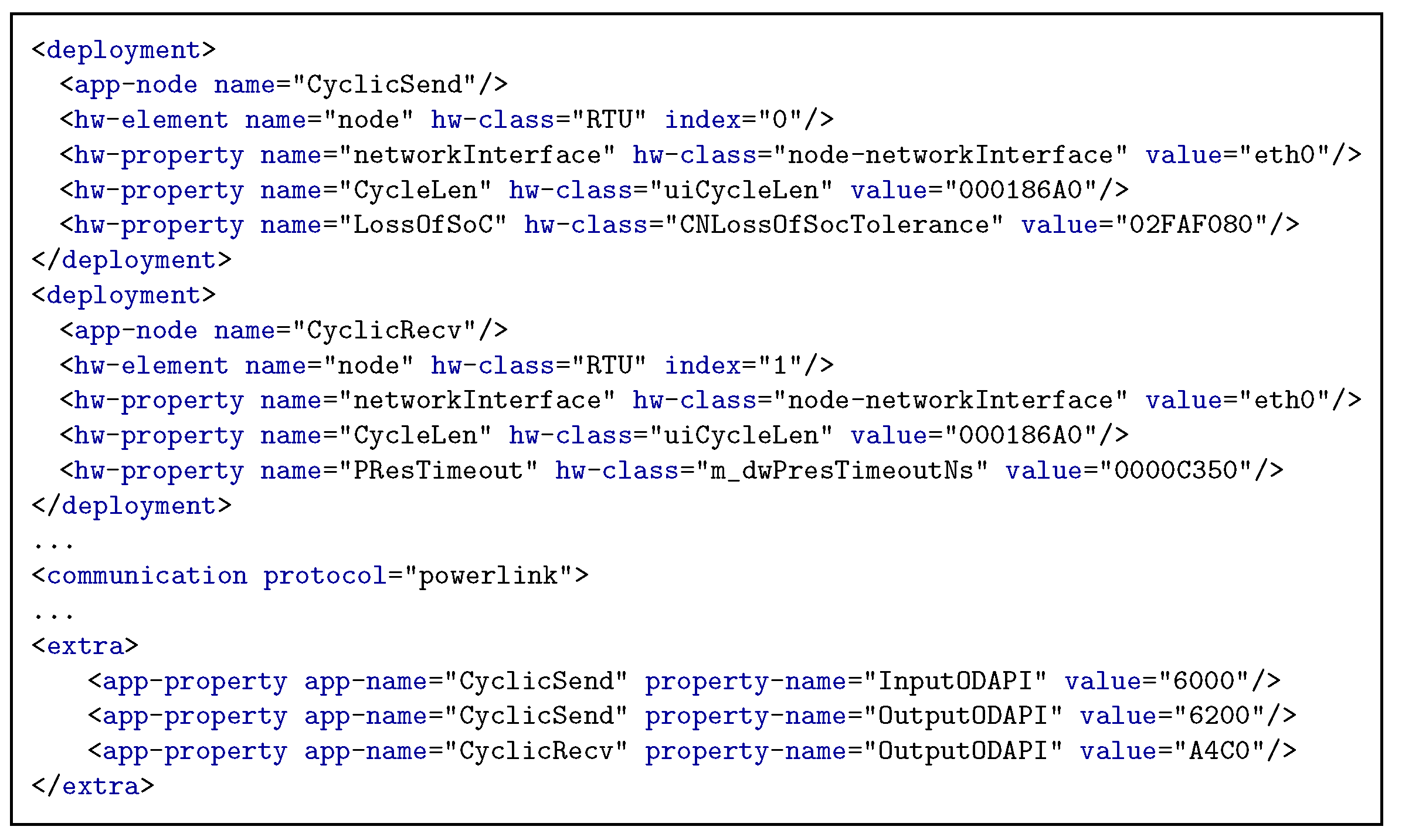
Specifically, the application deployment description (“mapping") is illustrated in
Figure 7. It consists of several mapping elements (“deployment") for each application processes (“app-node") that is bound to a device of the underlying architecture (“hw-element"), which is a hardware platform of certain type (“hw-class"). The device is identified in the hardware architecture by its index (“index"). The binding includes additional information, concerning the hardware platform (“hw-property"), that are necessary for establishing and configuring the communication between the network devices. This information can include the network interface name, the IP addresses of the destination network device, the port specification and the type of communication used (e.g., unicast, multicast and broadcast). The application deployment description may also contain additional elements which are application-specific and define particular characteristics of the hardware architecture or the application software, however they have to be specified in separate XML elements.
For industrial applications each specified application process (“app-node" in
Figure 11 is bound to a hardware architecture node (“hw-element"). Moreover, the additional information are characterizing the industrial applications and are defined under the “hw-property" XML element. These concern initially the type of considered network interface (i.e., hw-property name =“CycleLen"), considered for EPL as the Ethernet interface for the Linux environment (i.e., value =“eth0"). A second element concerns the EPL cycle length (i.e., hw-property name =“CycleLen"), which is crucial to the application functionality and therefore needs to be specified for each process of the PPM Application Model (
Section 2). An additional element is related to the tolerance timeout on the CN for the reception of the SoC frame which is transmitted by the MN in the beginning of each EPL cycle. This timeout (i.e., hw-property name =“LossOfSoC") is considered here equal to the value of the EPL cycle length multiplied by two and if it has elapsed the SoC frame is considered as lost. A final described element concerns the timeout for the reception of the poll responses (i.e., hw-property name =“PResTimeout").
3.4. Code generation from PPM-based industrial applications
The code generation method is a sequential process that is automated through the developed Algorithm 2.
|
Algorithm 2 Algorithm of Automated Code Generation |
- Require:
XMLAppFile, CCodeAppFile, XMLMapFile, PlatformFiles - Ensure:
Platform Dependent Code Generation - 1:
- 2:
- 3:
Builder builder; - 4:
procedure
- 5:
mkdir build directory, transfer default platform files - 6:
end procedure - 7:
procedure
- 8:
encode application structure into C Structures from Input XML - 9:
build process controller, copy input process C files and other library source files - 10:
end procedure - 11:
procedure
- 12:
allocate processes to the network devices - 13:
configure communication parameters of the underlying architecture - 14:
end procedure - 15:
procedure
- 16:
create main.c, create FIFOs, create and run processes - 17:
end procedure - 18:
procedure
- 19:
code compilation and library linking - 20:
end procedure |
In the initial (line 1) step the algorithm parses the PPM Application Model and in the second step (line 2), it parses the PPM Application Deployment (i.e., mapping) specification to orchestrate the code generation process. As a following step, it initializes the dedicated system builder according to the underlying architecture. Depending on the selection, different implementations of the generic functions provided in this algorithm will be chosen. The construct has a value “powerlink" for industrial systems. The method accordingly relies on the mapping specification to create the different hardware platform directories as well as to copy target platform specific files into them through the function (line 3). In the most important step of the algorithm the tool calls the function (line 6), in order to copy the process source, header and library files in the hardware platform directories. Afterwards, it creates a process controller C file per each input PPM process. The process controller contains all the necessary functions to control the execution of each process and to connect the process communication primitives with the communication interface of the target hardware platform. The (line 8) function call allocates processes to hardware platforms according to the input mapping specification. It then deducts the necessary communication parameters that need to be configured based on the supported protocol stack of underlying architecture. Finally, the tool generates the processes, shared objects ( function in line 10) and builds a makefile ( function in line 12) in order to simplify the compilation of the generated code.
The code generation method also includes a tool for the configuration of industrial devices using the openPOWERLINK stack described in Appendix A.
3.5. Firewall rule generation for industrial architectures
Rules are specified for each PPM process that has security requirements. They are included in the EPL or CANopen OD entry 1E81 [
5]. This index specifies entries the default policy for the forwarding and outbound communications with possible policy values: accept (1), drop (2) or reject (3).
Specifically, they are part of the PPM deployment XML description under the “rule" construct.
Figure 5 illustrates a rule to allow only incoming connections and packets that are EPL-complaint and block all the other legitimate or malicious Ethernet connections. More complex rules that can block a replay or masquerade attack using valid EPL packets can be specified using the “rule" construct. Finally, the node of the industrial architecture that the process is mapped to has also embedded these rules in its native Netfilter configurations.
4. Case study: Triple Modular Redundancy in a Power Plant
In this case-study we focused on demonstrating the method we described in
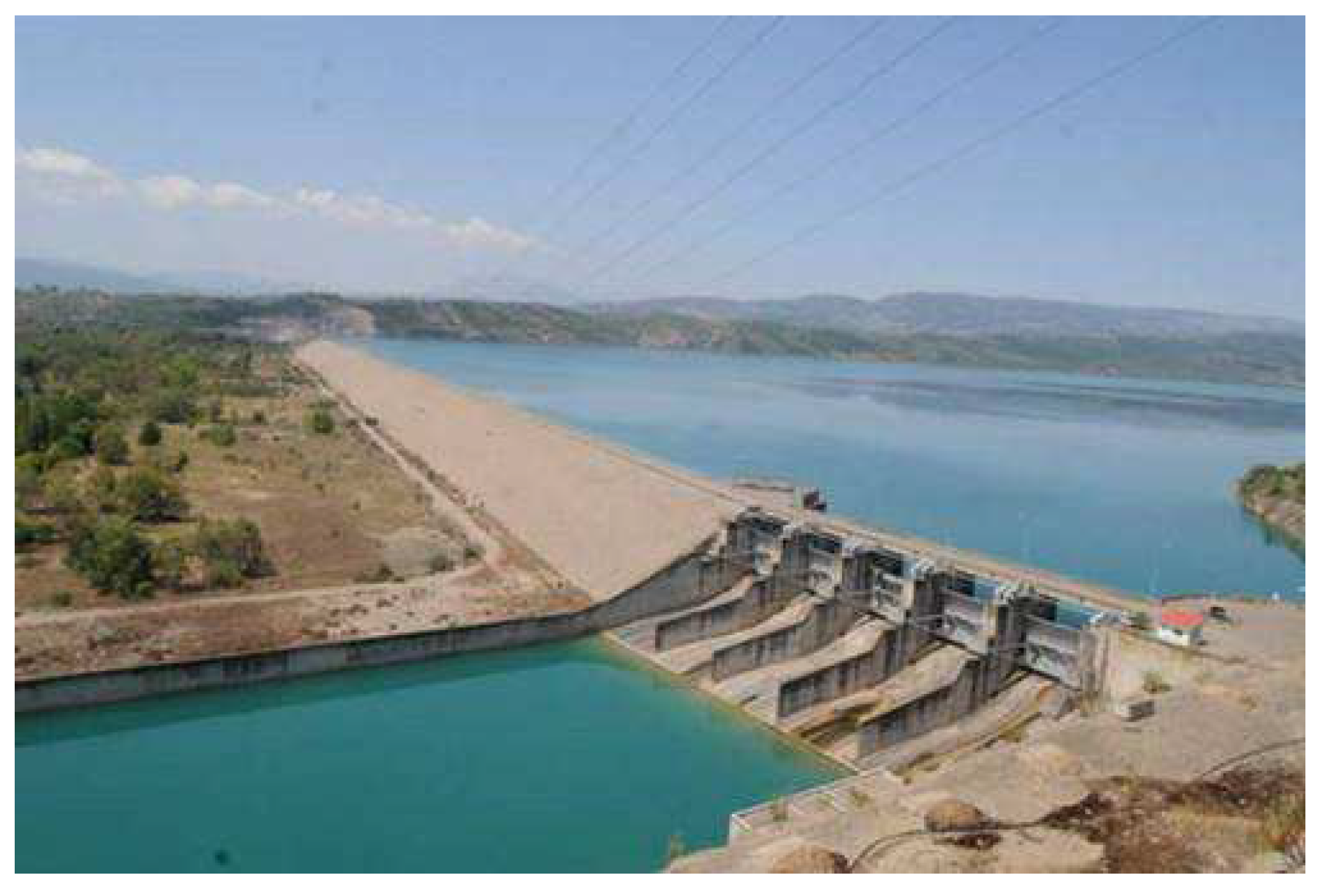
Section 3. Specifically, our objective was to automatically generate code for a Hydroelectric Power Plant (HPP) of the Public Power Corporation in Greece. The HPP is illustrated in
Figure 8.
The deployed setup on the HPP is commonly used in safety-critical Real-Time Ethernet applications to provide support for fault-tolerance through the Triple Modular Redundancy (TMR) mechanism [
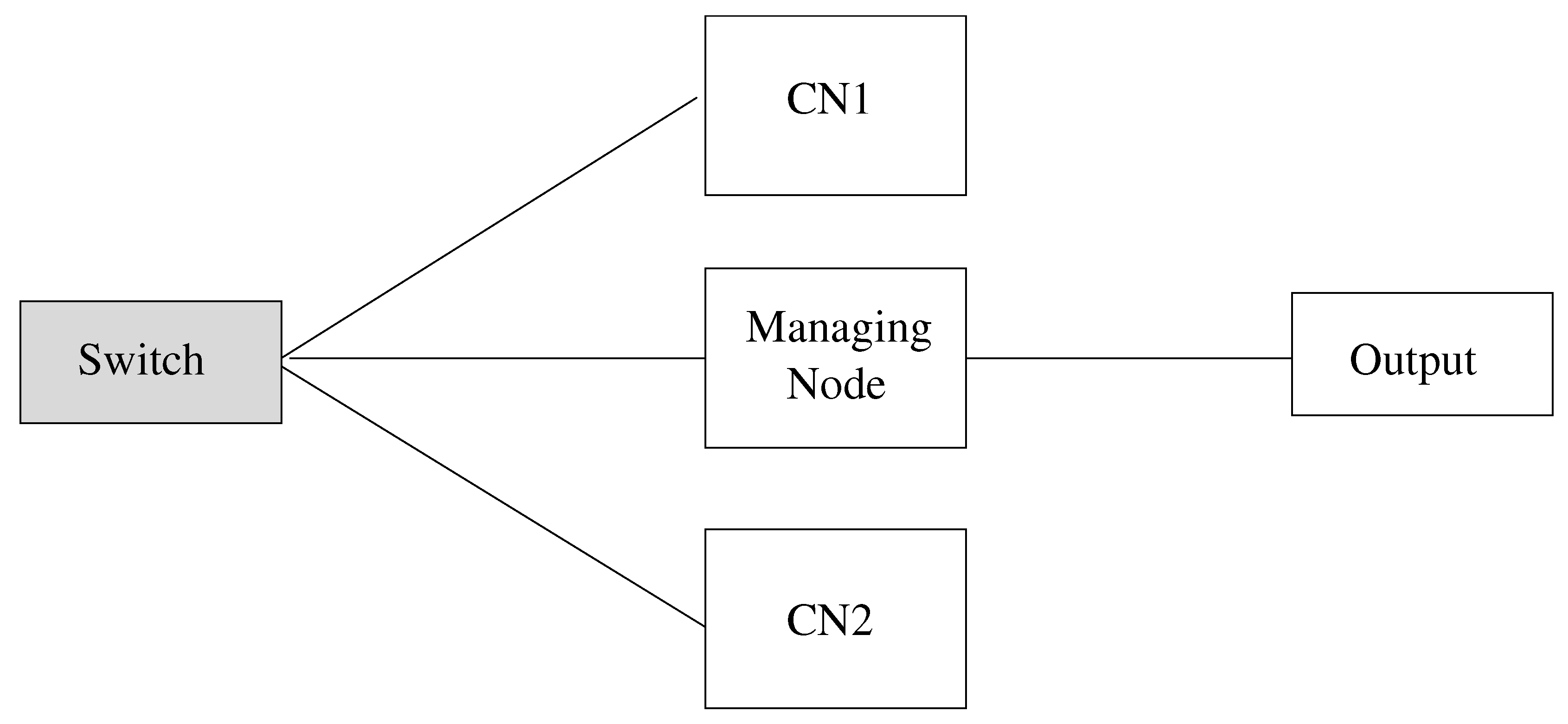
15]. This mechanism also aids in masking the failure of a component. In the particular network we have tested a basic industrial setup with one Managing Node (MN) and two Controlled Nodes (CNs) in a line topology which is illustrated in
Figure 9.
Each CN sends data to the MN through PRes frames containing PDO objects with the temperature and motion values of the power generator. If no change is made with respect to the previous measurements, the CN will repeat the transmission of the same measurements. The MN recognizes failures if the values that are received by the CNs are not consistent. When they are not consistent, the MN only considers values that are originating from the CN2 to provide the output in its native graphical user interface (GUI). The GUI of the MN implements the functionality of a Supervisory Control and Data Acquisition (SCADA) system [
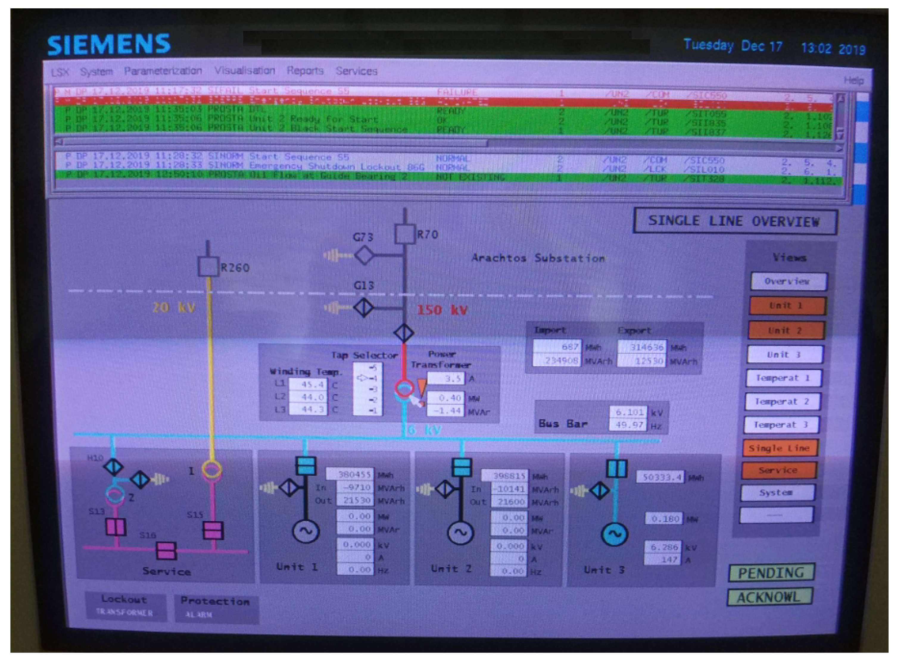
4], by allowing electrical network supervision as well as incident detection and mitigation. The software that is used to provide the GUI and SCADA functionalities for the MN is based on the proprietary Siemens software Totally Integrated Automation (TIA) portal that is illustrated in
Figure 10. Regarding the SDO objects, the TMR application only allows SDO’s transmitted by the MN for the configuration of the CNs’ OD entries during the initialization phase.
Each device has the role of a PLC implemented using a Raspberry Pi 3 Model B device
3, which is connected to a Sparkfun ESP32 Thing micro-controller
4. The EPS32 Thing is in turn connected to temperature and motion sensors, which control the temperature and rotor speed of the power generator respectively. Furthermore, the EPL network is supported by a 100 Mbps NETGEAR Gigabit Switch (GS105 model [
16]). Usually, EPL applications use a hub for their interconnections, however as this case-study is a small-scale application, the use of switch does not introduce significant communication latencies in the EPL network. Furthermore, for the device id we have used for CN1 EPL network id equal to 1, likewise for CN2 an id equal to 2 and for the Managing Node (MN) we used the defined by the standard id, equal to 240 [
6]. Finally, to allow early detection of incidents on the MN, a strong requirement of the TMR application lies in the deterministic time duration of the EPL cycle (synchronous and asynchronous part) that should be kept within 200ms. Hence, the temperature and motion inputs given by the CNs, should not have a significant time difference (less than 100 ms), as they might not be handled in the same EPL control loop.
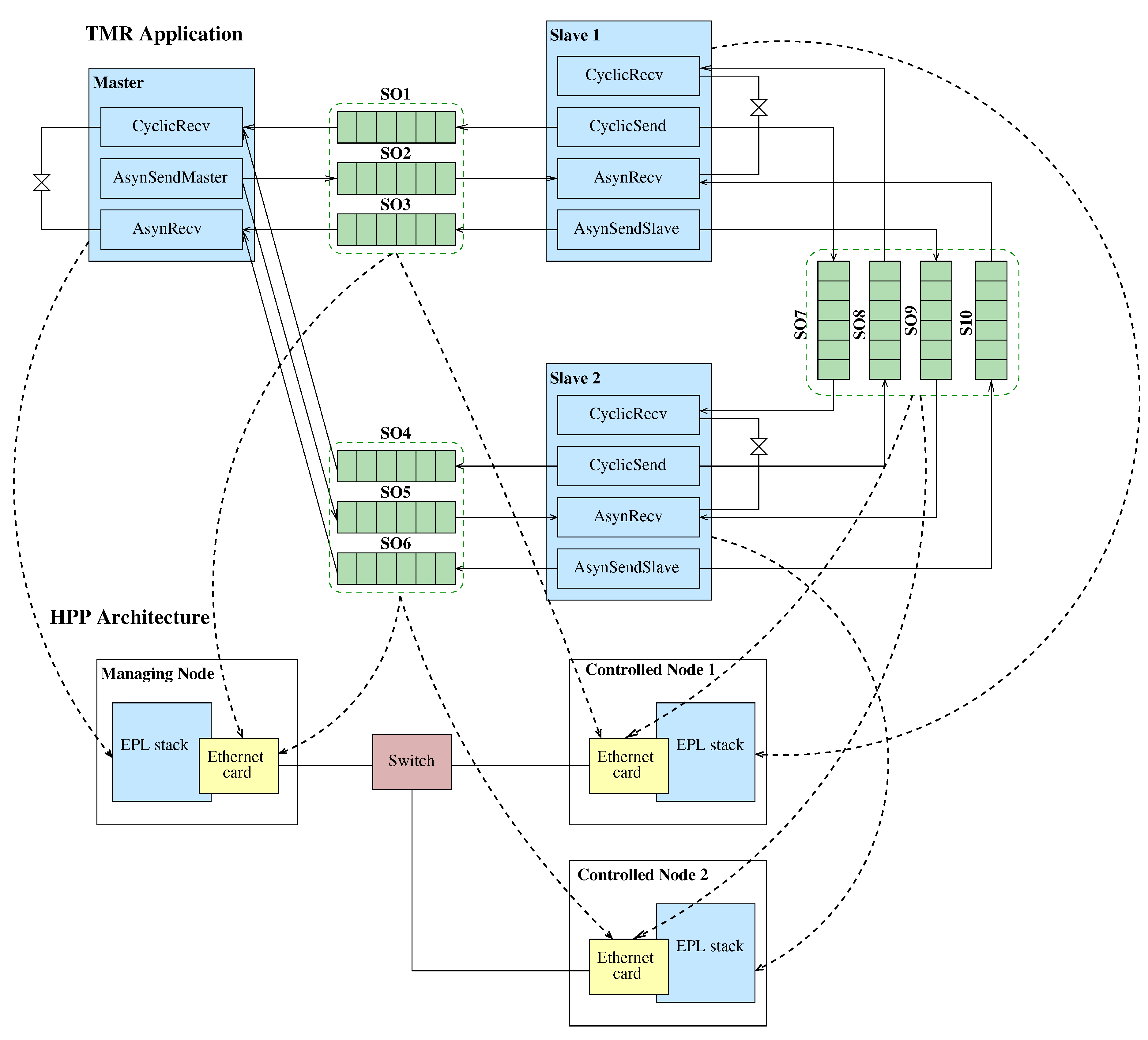
The deployment of the TMR CANopen Application in the underlying EPL architecture is illustrated in
Figure 11. Specifically, the processes of the Master block in the PPM Application Model are mapped to the EPL Managing Node in the EPL architecture. Likewise, the processes of the Slave block are mapped to the Controlled Nodes. Moreover, the FIFO shared objects are mapped to Ethernet cards of the devices of the underlying EPL architecture.
Figure 11.
Deployment of PPM Application Model in the Hydroelectric Power Plant plant’s architecture.
Figure 11.
Deployment of PPM Application Model in the Hydroelectric Power Plant plant’s architecture.
4.1. Experiments
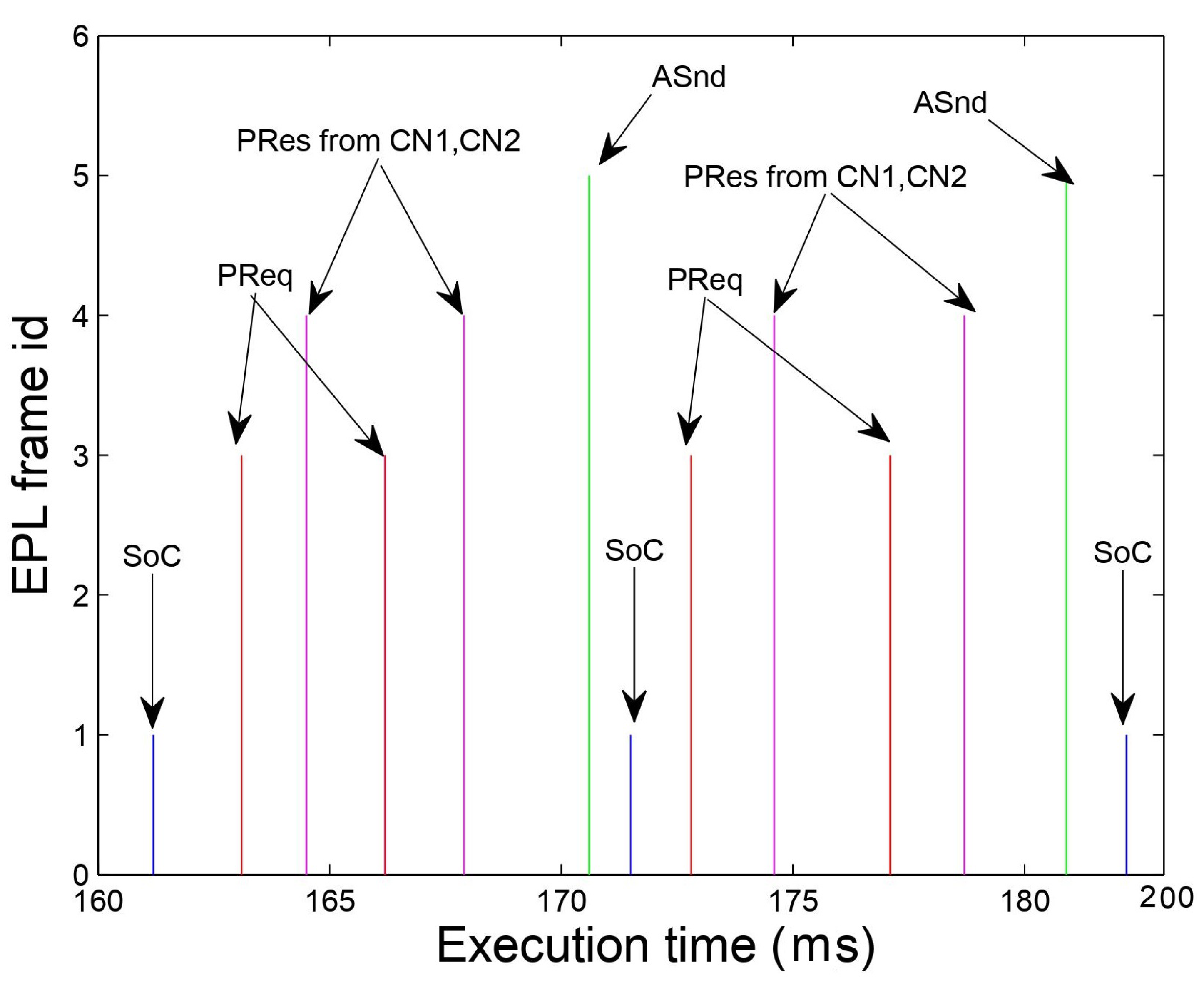
For our experiments we have focused on simulating and analyzing the behavior of the generated code for the TMR application over the EPL network. Thus, we have executed the application for 5 minutes, which corresponds to a large number of EPL control loops, each one taking approximately 100 ms. This can also be evaluated by
Figure 12, as the difference between two consequent SoC frames. In the same figure we can observe that the Managing Node (MN) transmits two subsequent PReq polling frames, which are correctly followed by the respective PRes poll-response frames from CN1 and CN2. Additionally, the times elapsed between PReq and PRes are sometimes different, which is due to the transmission latency of the network.
Moreover, the PReq frames issued by the MN to the CNs in the isochronous period are correctly followed by two subsequent PRes frames by each one of them. We can further observe that transmission of the SoA frame indicates as well the end of the EPL cycle, as no configuration data transmission is considered in this specific TMR application.
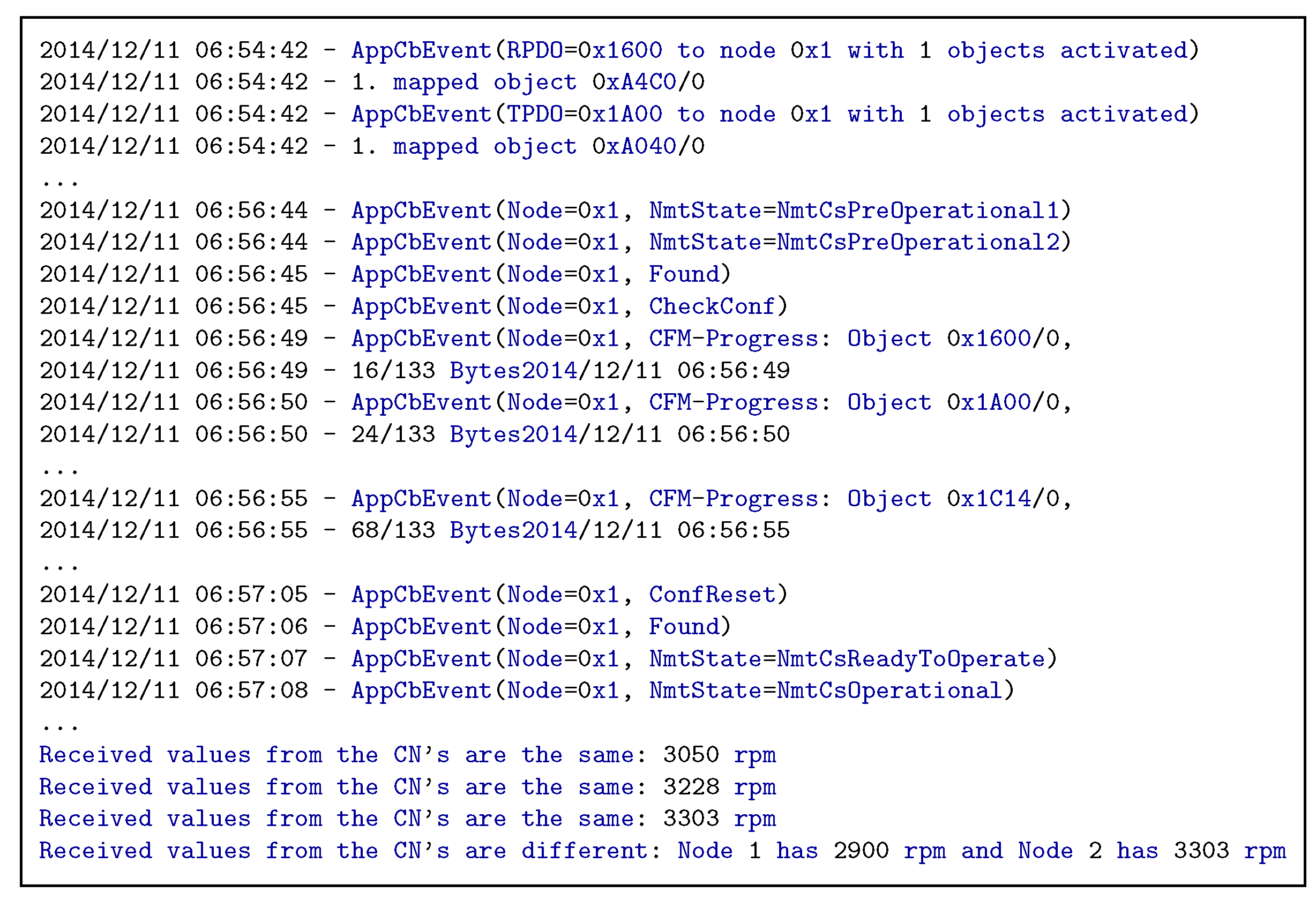
Figure 13 illustrates a fragment of the console output in the MN device. For the sake of comprehension, in this fragment we focus on the messages of only one CN (CN with id 1), concerning the management of its different states through the NMT state machine as well as its configuration (initialization of OD entries) as well. The former is presented in this fragment in lines 6-7 and 20-21, where we can observe how the MN sets the CN from the PreOperational1 to the PreOperational2 state for the configuration as well as from the ReadyToOperate to the Operational state once it is properly configured. On the other hand, lines 10-16 illustrate the successful configuration of OD entries in the CN through dedicated ASnd frames in the asynchronous phase, which in this case are the entries 1600, 1A00 and 1F98. The first two are used for the configuration of mapping parameters in the EPL, whereas the 1F98 OD entry is used to set the maximum size of the EPL or non-EPL frames that are transmitted during the asynchronous phase (value range between 300 and 1500 bytes). Apart from configuring the CN’s the MN performs also local PDO configurations (lines 1 to 4), indicating where the RPDO and TPDO are to be mapped respectively. The application functionality is presented in the lines 23 to 25, where we can see that the motion input values for the rotor speed from the CN’s match and are displayed in the MN console in a decimal ASCII form. As a next step, we have introduced a faulty reading on CN1 to verify 1) if the rotor speed remained intact as well as 2) if an incident was logged on the diagnostic output of the MN node and subsequently on the SCADA system. Through our experiments, we verified that a difference in readings appeared on MN’s diagnostic output as illustrated in line 26 of
Figure 13 as well as a FAILURE incident appeared in MN’s SCADA system i.e., red lettered indication in
Figure 10. Furthermore, the rotor’s speed remained intact in the 3303 rpm.
5. Discussion
5.1. Benefits of the proposed method
The method that is illustrated in
Figure 4 supports the automated generation of executable code for Real-Time Ethernet architectures. The executable code covers 1) functional aspects 3) the configuration of the industrial network nodes through CANopen profiles and 3) cyber-resilience aspects through firewall rules. A significant benefit of the method is that it uses configurable code templates for both the application software and the libraries for the communication in the underlying architecture. This allows to generate code rapidly for any application by only modifying the parameters of application processes in a high-level and user-friendly XML format. Additionally, it also allows the method to be ported quickly into similar projects.
The reason for such benefit is the reusable code artifacts and the modularity of the method, which builds upon atomic functionalities of each industrial system. The atomicity of each functionality also reduces the application complexity. The TMR application that is illustrated in
Section 4 aims at testing the effectiveness of our approach and the satisfaction of the industrial application tight requirements when deployed in the underlying architecture.
Table 1 reports figures for the required effort and code artifacts for the case study. Each row refers to a particular step of the proposed method, however Step 5 refers to the overall effort for building the tool that would allow automated code generation based on the PPM process model.
Overall the generated code for the case study consisted of 13169 lines of code spread into 118 files. From these files, 42 were deployed in the Managing Node with 4619 lines in total for the TMR application and the remaining were equally deployed in the 2 Controlled Nodes. This means per Controlled Node there were 38 files and 4275 lines of code. Apart from this code the Managing Node had had 4 configuration files and each Controlled Node another 2 files for the configuration of the EPL nodes (node configurations described in Appendix A).
5.2. Limitations
The method relies on the identification of processes that implement atomic functionalities of each industrial application. This is a manual step that requires conceptual thinking from the system designer and is vital for the proper system operation. The illustrated case-study of
Section 4 depicts a realistic scenario that can be deployed in as a testbed in a small production line. In this scenario there is no overlap in application functionalities allowing to distinguish the atomic functionalities and constructing the PPM process network without considerable effort. The ultimate goal of Industry 4.0 area though is to bring automation in larger production lines. Hence, production lines will require to handle multiple operational tasks, thus increasing the number of functionalities that need to be considered in the application. Given the current form of our method, the application designer will have a substantial manual effort. To this end, we plan to add further automation in the initial steps (Steps 1 and 2) of our method to avoid such scalability issues.
The current applicability scope of our methods is on building rapidly or updating EPL-compliant systems. This is due to the available application and architectural code artifacts of our method. For widening the application to other Real-Time Ethernet system architectures (e.g., EtherCAT [
17], PROFINET RT [
18]), it is essential to enrich the develop code artifacts. Except from EPL that has the open-source openPOWERLINK stack, the rest of Real-Time Ethernet protocols have proprietary libraries and stacks for the development of industrial applications. This is a considerable limitation as many industrial manufacturers are already using in their production lines third-party equipment that employs some of these protocols, such as the EtherCAT implementation on NXP’s P2020 processor [
19]. Furthermore, the Real-Time Ethernet network is usually be installed and configured by supply-chain personnel [
20], hence control and automation engineers might have knowledge only for its operation and not the installation. Therefore, extending our method with new libraries and stacks to bring business benefits will require a substantial initial effort. Despite this initial effort though, the individual steps of the presented method will not be affected by this enrichment.
5.3. Comparison with similar methods
The Industry 4.0 area involves a lot of proprietary communication technologies as well as infrastructure systems. Along with these technologies vendors also provide tools to facilitate the development of functional applications. The tools allow simulation, testing and validation of system requirements as well as rapid prototyping, in order to automate code generation for industrial architectures. To better position our work in comparison with these tools we hereby provide three categories of related work in literature. Each category focuses on state-of-the-art work on the three main benefits of our method (
Section 5.1).
Code generation for traditional Ethernet architectures
An interesting toolbox for distributed industrial control systems, is provided by PLCTOOLS [
21]. PLCTOOLS is able to describe such systems in different levels from the design of function block diagrams (FBDs) to timed Petri-Nets for validating the design as well as can generate executable C code for their architecture. However, the generated code is not deployable since it cannot be deployed in the industrial infrastructure but rather runs through a dedicated engine.
Code generation for industrial applications is also handled by Mathwork’s Simulink, which includes the Simulink PLC Coder library. This library allows to generate Ladder Diagrams describing the application logic of PLCs. The library supports many well-known PLC vendors, which can use the Ladder Diagrams for compilation and flashing to the PLC the executable code. Alternatively, the Ladder diagrams can be used for application simulation in the native Matlab environment. Another work towards this direction has been conducted in CERN [
22] and the authors use code generators for PLC and SCADA systems. The code generators concern the control logic, communication interfaces and device configurations. Nevertheless, these libraries does not support Real-Time Ethernet protocols and can rather be used in traditional industrial architectures.
Node configuration/performance analysis in Real-Time Ethernet
As Industry 4.0 is a fairly new area in industrial systems considerable work has been done into their simulation and validation instead of code generation for rapid prototyping. Specifically, the authors in [
23] use the OPNET Modeler framework
5 to simulate and analyze the performance and impact of automation in industrial systems, which use the EPL protocol in their network stack. The conducted sets of extensive simulations are considering several performance indicators as well the presence of notifications in the form of alarm frames in the asynchronous phase of the EPL cycle. Though the developed models are generic, the use of the OPNET Modeler framework is limited in terms of customizability as well as it does not allow addressing and validating system requirements or the generation of deployable code for such systems.
Node configuration in our method is using CANopen profiles, which provides automation and flexibility for industrial applications. Nevertheless, CANopen was initially developed and is still being used for the configuration of Controller Area Network (CAN) [
24] applications, hence its integration with EPL architectures are considerably lower. When used it allows faster configuration of safety applications, such as the scenario of controlling lifts [
25]. In this scenario the application configuration with CANopen allows to satisfy the requirements even under failure conditions of the mechanical components. However, the node configuration requires substantial effort for parameters related to the TPDO and RPDO CANopen objects (e.g., payload size, frame timeout). Hence, the automatic configuration of CANopen-complaint nodes of our method aids in faster development of similar applications.
To expand CANopen’s usage the configuration and analysis of the performance for CANopen applications Vector has provided an extension to its well-known tools CANoe and CANalyzer
6. Nevertheless, as these tools require a proprietary license and their evaluation version allows only the configuration of simple CANopen applications. Moreover, the use of the CANoe and CANalyzer toolkits in industrial applications requires adequate knowledge as well as often it cannot be always used as a standalone method for application development, since it often requires the implementation of additional interfaces [
26].
Cyber-resilience for traditional Ethernet architectures
Another contribution of our method is related to cyber-resilience through automated firewall rule generation. Several tools has been presented in literature related to the generation of rules for protection of traditional Ethernet architectures
7 8 . However, most tools do not rely on semantics for the generation, except the Mignis tool [
9]. Mignis defines relies on a configuration file to generate rules for any architecture, that can be also verified formally. Our work extends Mignis configurations to not only protect traditional Ethernet architectures, but also to provide protection through EPL-specific configurations for the Real-Time Ethernet architecture.
6. Conclusion
We presented a novel method for automating the generation of reliable executable code for industrial applications from high-level programming models. The method takes as input the application model described as a Kahn process network, a XML-based mapping of the application to the hardware architecture as well as code templates describing the application behavior and the hardware architecture that is using Ethernet Powerlink protocol and CANopen communication profiles for data exchange. Afterwards, it generates executable code for the architecture and configurations for the devices of the hardware architecture. We demonstrate the method in an industrial plant case-study, which provides support for fault-tolerance through the Triple Modular Redundancy (TMR) mechanism. The executable code is deployed in Programmable Logic Controllers (PLCs) of the industrial plant, in order to control the temperature and rotor speed of a power generator. The power generator is responsible for electricity production in a Hydroelectric Power Plant (HPP) of the Public Power Corporation (PPC). As an outcome, the case-study provides reliability under both normal and error-prone operating conditions.
An interesting extension for this work concerns the automatic generation of the industrial application model and the Mapping from specifications of the CANopen application software. One interesting direction in this scope is to extend the NETCARBENCH specification [
27] for industrial automation systems. Then, we plan to develop a tool, which will be using the XSLT transformation language [
28] and its native style-sheets to transform the input specifications to dedicated XML files for describing the Kahn process network as well as the architecture deployment.
Additionally, as a part of our future work we plan to investigate the more complex architectures for Real-Time Ethernet, than the considered Triple Modular Redundancy application in this article. This will allow us to automate the initial steps (i.e., Step 1 and 2) of your method towards the separation of the application behavior into processes of the Kahn network, when there are overlapping functionalities. A particularly interesting architecture using several communication layers as in Computer Integrated Manufacturing (CIM) systems [
23]. Each layer in such systems is supported by a dedicated switch, which introduces forwarded messages along with the usual transmitted and received. Additionally, such messages include overlapping functionalities. Along with this extension we consider building a tool that extracts atomic and non-overlapping functionalities from the application behavior, to remove this manual effort from the application designer.
Finally, we also plan to consider transmission errors related to electromagnetic noise in Real-Time Ethernet architectures that are frequently encountered in industrial environments [
29]. These errors have a strong impact on the performance of the network and may cause loss of the transmitted frames, but also their corruption or duplication.
Funding
This research received no external funding.
Institutional Review Board Statement
Not applicable
Informed Consent Statement
Not applicable
Data Availability Statement
The datasets generated and/or analyzed during the current work are available upon request.
Conflicts of Interest
The authors declare no conflict of interest.
Appendix A. *
Appendix A: Industrial node configuration
The process of generating specific configurations for the nodes that implement the openPOWERLINK stack takes place in step 3 of
Figure 4. As input it receives the device configuration files for each node in CANopen or EPL conforming format
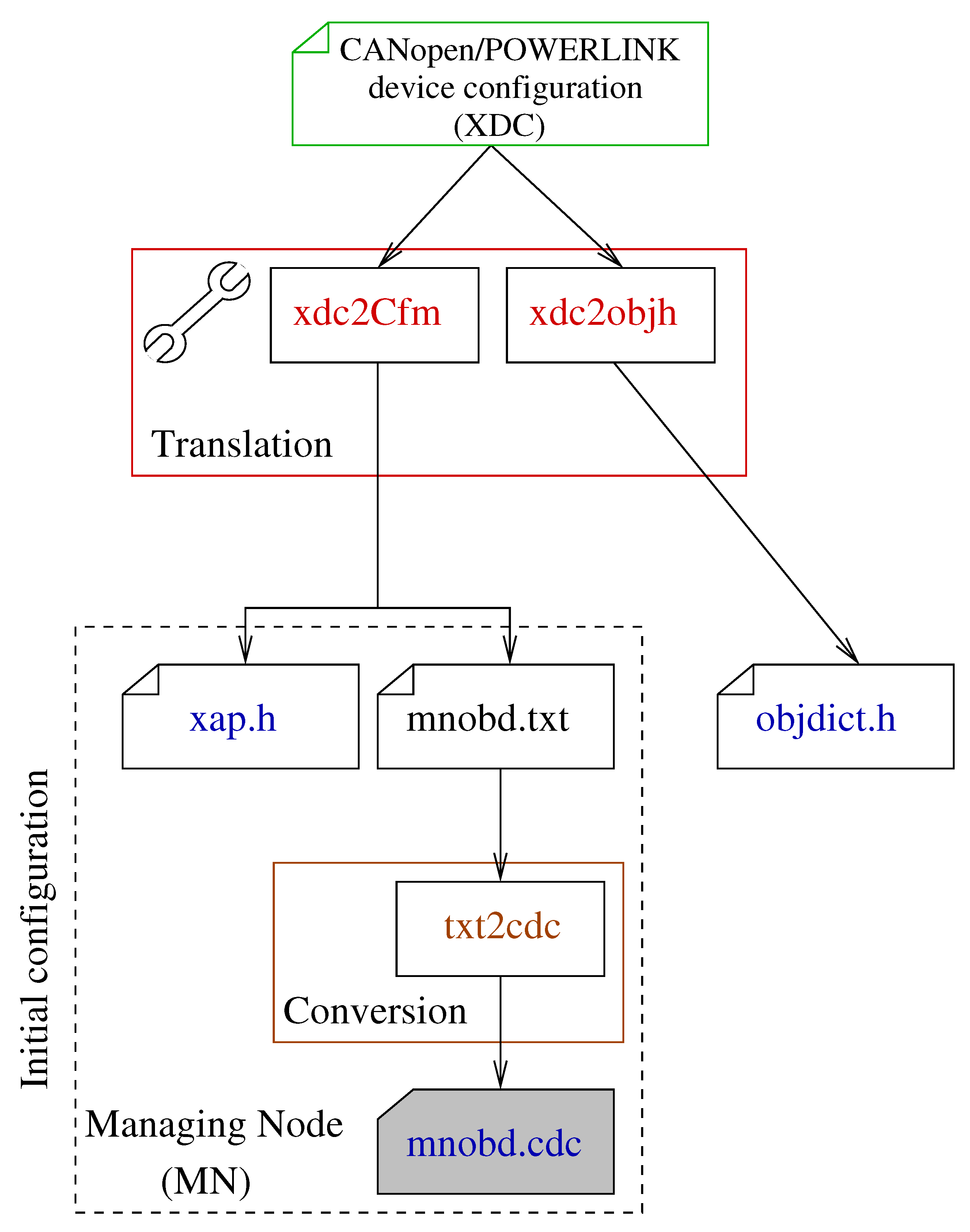
9. The developed tool consists of two XML translators: the xdc2objh and the xdc2Cfm. The xdc2objh translator parses every device configuration file and creates a header file (
objdict.h) for the OD module of the stack. This file contains the definition of each object used in the communication or device profile. Consequently, the xdc2Cfm translator identifies the MN device configuration and extracts linking information for the API layer in order to add them to a stack-specific file (
xap.h), which provides access to OD modules from the EPL Application layer. It additionally extracts the initial values for the OD objects of all the device configurations, in order to use them in the object initialization phase. All these information are evenly added in a stack-specific file (
mnobd.txt), which is latter converted to a binary file (
mnobd.cdc) through the txt2cdc tool that is available in openCONFIGURATOR
10. The output binary file is used by the MN node.
Figure A1.
Configuration generator tool for EPL nodes.
Figure A1.
Configuration generator tool for EPL nodes.
References
- Mosterman, P.J.; Zander, J. Industry 4.0 as a cyber-physical system study. Software & Systems Modeling 2016, 15, 17–29. [Google Scholar]
- Felser, M. Real-time ethernet–industry prospective. Proceedings of the IEEE 2005, 93, 1118–1129. [Google Scholar] [CrossRef]
- Moyne, J.R.; Tilbury, D.M. The emergence of industrial control networks for manufacturing control, diagnostics, and safety data. Proceedings of the IEEE 2007, 95, 29–47. [Google Scholar] [CrossRef]
- Galloway, B.; Hancke, G.P. Introduction to industrial control networks. IEEE Communications surveys & tutorials 2012, 15, 860–880. [Google Scholar]
- Standard, E.D. 301, Ethernet POWERLINK Communication Profile Specification Version 1.3. 0, 2016.
- Std., I.E.C. IEC 61784: Digital data communications for measurement and control – Part 2: Additional profiles for ISO/IEC8802-3 based communication networks in real–time applications. 20 July.
- Lekidis, A.; Bozga, M.; Bensalem, S. Model-based validation of CANopen systems. In Proceedings of the 2014 10th IEEE Workshop on Factory Communication Systems (WFCS 2014). IEEE; 2014; pp. 1–10. [Google Scholar]
- Kriaa, S.; Pietre-Cambacedes, L.; Bouissou, M.; Halgand, Y. A survey of approaches combining safety and security for industrial control systems. Reliability engineering & system safety 2015, 139, 156–178. [Google Scholar]
- Adao, P.; Bozzato, C.; Dei Rossi, G.; Focardi, R.; Luccio, F.L. Mignis: A semantic based tool for firewall configuration. In Proceedings of the 2014 IEEE 27th Computer Security Foundations Symposium. IEEE; 2014; pp. 351–365. [Google Scholar]
- Wool, A. A quantitative study of firewall configuration errors. Computer 2004, 37, 62–67. [Google Scholar] [CrossRef]
- Baumgartner, J.; Schoenegger, S. POWERLINK and Real-Time Linux: A Perfect Match for Highest Performance in Real Applications. In Proceedings of the Twelfth Real-Time Linux Workshop, Nairobi, Kenya; 2010. [Google Scholar]
- Pfeiffer, O.; Ayre, A.; Keydel, C. Embedded networking with CAN and CANopen; Copperhill Media, 2008.
- Lekidis, A.; Bourgos, P.; Simplice, D.D.; Bozga, M.; Bensalem, S. Building Distributed Sensor Network Applications using BIP. In Proceedings of the IEEE Sensors Applications Symposium (SAS). IEEE; 2015; pp. 1–6. [Google Scholar]
- Thiele, L.; Bacivarov, I.; Haid, W.; Huang, K. Mapping Applications to Tiled Multiprocessor Embedded Systems. In Proceedings of the Proceedings of the Seventh International Conference on Application of Concurrency to System Design; ACSD ’07; IEEE Computer Society: Washington, DC, USA, 2007; pp. 29–40. [Google Scholar] [CrossRef]
- Kopetz, H. Real-time systems: Design principles for distributed embedded applications; Springer: 2011.
- NETGEAR. ProSafe 5-port and 8-port Gigabit Desktop Switches 10/100/1000 Mbps. Available online: http://www.netgear.ru/images/GS105v3_GS108v3_DS_27Apr1170-4903.pdf.
- Jansen, D.; Buttner, H. Real-time Ethernet: The EtherCAT solution. Computing and Control Engineering 2004, 15, 16–21. [Google Scholar] [CrossRef]
- Ferrari, P.; Flammini, A.; Venturini, F.; Augelli, A. Large PROFINET IO RT networks for factory automation: A case study. In Proceedings of the ETFA2011. IEEE; 2011; pp. 1–4. [Google Scholar]
- Orfanus, D.; Indergaard, R.; Prytz, G.; Wien, T. EtherCAT-based platform for distributed control in high-performance industrial applications. In Proceedings of the 2013 IEEE 18th Conference on Emerging Technologies &, 2013, Factory Automation (ETFA). IEEE; pp. 1–8.
- Hood, G.W.; Hall, K.H.; Chand, S.; D’mura, P.R.; Kalan, M.D.; Plache, K.S. Module and controller operation for industrial control systems, 2011. US Patent 7,912, 560.
- Baresi, L.; Mauri, M.; Monti, A.; Pezze, M. PLCTools: Design, formal validation, and code generation for programmable controllers. In Proceedings of the Smc 2000 conference proceedings. 2000 ieee international conference on systems, man and cybernetics.’cybernetics evolving to systems, humans, organizations, 2000, Vol. 4, and their complex interactions’(cat. no. 0. IEEE; pp. 2437–2442.
- Fernandez Adiego, B.; Prieto Barreiro, I.; Blanco Vinuela, E. UNICOS CPC6: Automated code generation for process control applications. In Proceedings of the Conf. Proc., Vol. 111010, p. WEPKS033. 2011. [Google Scholar]
- Cena, G.; Seno, L.; Valenzano, A.; Vitturi, S. Performance analysis of Ethernet Powerlink networks for distributed control and automation systems. Computer Standards & Interfaces 2009, 31, 566–572. [Google Scholar]
- Di Natale, M.; Zeng, H.; Giusto, P.; Ghosal, A. Understanding and using the controller area network communication protocol: Theory and practice; Springer Science & Business Media, 2012. [Google Scholar]
- Soury, A.; Charfi, M.; Genon-Catalot, D.; Thiriet, J.M. Performance analysis of Ethernet Powerlink protocol: Application to a new lift system generation. In Proceedings of the 2015 IEEE 20th Conference on Emerging Technologies &, 2015, Factory Automation (ETFA). IEEE; pp. 1–6.
- Molfese, C.; Schipani, P.; Marty, L.; Esposito, F.; D’Orsi, S.; Debei, S.; Bettanini, C.; Aboudan, A.; Colombatti, G.; Mugnuolo, R.; et al. The EGSE for the DREAMS payload onboard the ExoMars 2016 space mission. In Proceedings of the 2014 IEEE Metrology for Aerospace (MetroAeroSpace). IEEE; 2014; pp. 337–341. [Google Scholar]
- Braun, C.; Havet, L.; Navet, N. NETCARBENCH: A benchmark for techniques and tools used in the design of automotive communication systems. 2007.
- Clark, J.; et al. Xsl transformations (xslt). World Wide Web Consortium (W3C). Available online: http://www. w3. org/TR/xslt.
- Decotignie, J.D. Ethernet-based real-time and industrial communications. Proceedings of the IEEE 2005, 93, 1102–1117. [Google Scholar] [CrossRef]
|
Disclaimer/Publisher’s Note: The statements, opinions and data contained in all publications are solely those of the individual author(s) and contributor(s) and not of MDPI and/or the editor(s). MDPI and/or the editor(s) disclaim responsibility for any injury to people or property resulting from any ideas, methods, instructions or products referred to in the content. |
© 2023 by the authors. Licensee MDPI, Basel, Switzerland. This article is an open access article distributed under the terms and conditions of the Creative Commons Attribution (CC BY) license (http://creativecommons.org/licenses/by/4.0/).
