Preprint
Article

Improved Transient Performance of DFIG-Based Wind-Power System Using Combined Control of Active Crowbars

Altmetrics

Downloads

121

Views

35

Comments

0

A peer-reviewed article of this preprint also exists.

This version is not peer-reviewed

Submitted:

29 August 2023

Posted:

31 August 2023

You are already at the latest version

Alerts
Abstract
A significant electromotive force is induced in the rotor circuit of a doubly fed induction generator (DFIG) due to its high vulnerability to grid faults. Therefore, the system performance must be increased with appropriate control actions that can successfully offset such abnormalities in order to provide consistent and stable operations during grid disturbances. In this regard, this paper presents a solution based on a combination of an energy storage-based crowbar and a rotor-side crowbar that makes the effective transient current and voltage suppression for wind-driven DFIG possible. The core of the solution is its ability to restrict the transient rotor and stator overcurrents and DC-link overvoltages within their prescribed limits, aiming to protect the DFIG and power converters, and consequently, improve the system’ ability to ride-through faults. Further, the capacity of an energy storage device for transient suppression is estimated. Finally, simulation results show that the proposed approach is effective in achieving transient control objectives precisely and maintaining a stable grid connection during the faults.
Keywords: 
Subject: Engineering  -   Electrical and Electronic Engineering

1. Introduction

With an increased interest in achieving the electrical energy requirements from renewable energy sources, massive integration of wind power is rising worldwide. However, at the same time, it has opened new research areas in respect of successful integration of wind-power plants (WPPs) to the electrical power network [1], stable system operations [2], and to assist the grid during transients [3]. Thus, the improved system reliability can be achieved if the WPPs continue to be coupled to the grid during grid disturbances and assist transient voltage suppression. This has compelled many power companies to updates their grid codes on account of grid integration and operation of the wind turbines (WTs) [4]. Among them, the main concern is the successful implementation of the low-voltage ride-through (LVRT) ability of the wind-power systems [5].
Significant developments in high efficiency and reliability have been achieved since the variable-speed concept emerged in WT operations [6]. Presently, doubly fed induction generators (DFIGs) are the widespread choice for wind-turbine-generators (WTGs) due to flexible speed operation, high efficiency, and low-rating converters [7]. A DFIG is highly prone to grid disturbances because of having a direct connection to the grid via its stator circuit. Due to low rated rotor-side converter (RSC) and DC-link voltage restrictions, the rotor circuit experiences a significant electromotive force (EMF) during faults [8]. Thus, it is anticipated that the wind-power converters (i.e., RSC and grid-side converter (GSC)) will experience overcurrents that induces transient overvoltages in the DC circuit that links them.
To enable the WPPs to successfully ride-through grid disturbances, many power companies have updated their grid codes. Exhaustive efforts have been made to ensure this, and several solutions have been provided to boost the LVRT potential of the DFIG-based wind-energy conversion systems (WECSs). To highlight the contributions of the present study, it is therefore, necessary to present a critical analysis of the start-of-the-art techniques proposed for the successful handling of LVRT. The conventional vector controls are incapable of properly controlling the DFIGs under grid faults because a sizable EMF caused by voltage dips may initiate substantial transient currents in the RSC and the DFIGURE Besides, the stator-natural flux caused by grid-voltage dips declines sluggishly with typical vector controls, lengthening the transient process.
Several studies are available in literature that provided various technical solutions to deal with the power-system stability problems and improve the LVRT capability of DFIG-based WECSs. These solutions can largely be divided into two subgroups: (1) improved control structures for DFIGs and (2) enhanced external hardware-based solutions. Numerous modified control schemes have been presented in [7,9,10,11,12,13,14,15,16,17,18,19,20] such as feedforward current-references control [7], flux-linkage control [9], demagnetization control [10], modified controls for RSC [11], flux magnitude and angle control [12], sliding-mode control [13,14], negative-sequence current regulation [15], an enhanced reactive power support [16], and an improved control design for wind-power converters [17]. A double impedance-substitution control approach to expand the LVRT capability of a DFIG was suggested in [18]. A study of the transient stability of DFIG-based WT system was presented in [19], in which phase-locked loop and current control loops were considered. Lyapunov’s methods were used to examine the stability of the system. The authors of [20] proposed a method in reference to feedforward control loops to alleviate the negative effects of transient rotor currents and stator voltages on DFIG during grid disturbances. The improved WTG controls performed effectively in suppressing the transient currents and voltages of the DFIG and the power converters, in addition to accelerating the flux-decaying process so as the transient phenomenon can be short.
Modern WTs most frequently include assisting hardware, like crowbar protection [8,21,22], to mitigate DC-link voltage variations. Presently, the application of fault-current limiters (FCLs) such as an inductive bridge-type FCL [23] and a capacitive bridge-type FCL [5,24,25,26], has attracted special attention as a prospective solution for LVRT enhancement. Other hardware applications, such as a STATCOM [27], an energy storage device (ESD) [22,28], and a dynamic voltage restorer [29], have also been recommended. To overwhelm the negative-sequence voltage during faults, the authors of [30] developed a control scheme based on an active voltage equalization dynamic control. An analytical method based on the fault current characteristics to handle the ride-through capability of DFIG was established in [31] in which a switching mechanism between RSC control and crowbar was proposed.
Under serious grid faults, large transient rotor overcurrents are generated, which also flow into the DC-link, rendering the DFIG uncontrollable. The decoupled control of the RSC and GSC may be destroyed by the DC-link voltage fluctuations. Further, large fluctuations in the electromagnetic torque will be originated. These undesirable effects may result the failure of mechanical and electrical components, as well as may disastrous for safe system operation and worsen the power quality.
To accommodate the massive integration of wind energy successfully, suitable changes in the system and its control mechanism are required. Concerning this, the authors intended to establish a control design based on employing active crowbars, embedded into the WTG controls that can facilitate improved system performance during transient conditions and could ensure stability and quality operations.
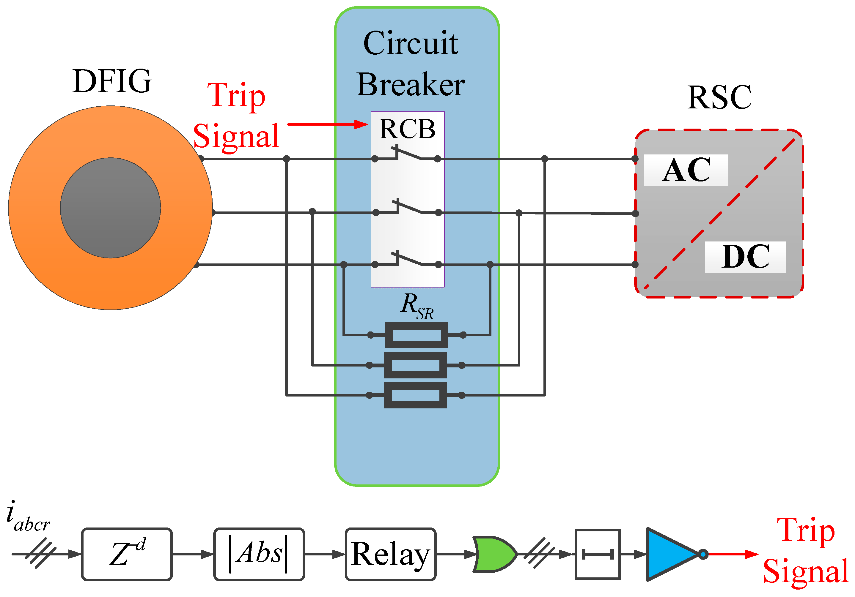
The ultimate objectives of this study and the proposed technical solutions to achieve them can be classified into two sets and are briefly stated as follows: Enhancing the LVRT operation of a DFIG by developing control schemes based on auxiliary crowbar controls. To limit the transient rotor currents, an active crowbar at the rotor-side is designed, in which a set of resistors is paralleled with a rotor circuit breaker (RCB) and are connected to the RSC. At the DC-link, another crowbar comprises an ESD, a battery in this study, is proposed and inserted in parallel to it. The proposed combined control scheme of active crowbars effectively enhanced the DC-link behavior in support of the grid during faults.
The contributions of this study are as follows:
  • Efficient and effective control schemes based on crowbar controls were designed to cater to the transient effects of rotor current and DC-link voltage throughout grid instabilities, strengthening the LVRT capability of the DFIG and improving the transient performance of the system.
  • The proposed method is a promising solution for realizing the LVRT capability, owing to its ability to mitigate the transient effects in generator electromagnetic torque. Moreover, the proposed design is suitable for wind-energy systems due to its the practical implementation.
The rest of the paper is organized into six sections. Basic explanation of the wind-driven DFIG system is presented in Section 2. A comprehensive mathematical modeling and analysis of a DFIG is reviewed in Section 3. Exhaustive mathematical formulation, designed procedures, and evaluations of the proposed control schemes are provided in Section 4. The capacity estimation of ESD required for LVRT is provided in Section 5. To examine the performances of proposed control schemes, simulation studies for a 1.5 MW DFIG system are presented and addressed in Section 6. Further, a comparison of the proposed scheme with the DC-chopper is performed. Finally, the paper is concluded in Section 7.

2. Overview of a DFIG-WT System

A comprehensive diagram of a DFIG-based WT system is shown in Figure 1. It comprises a WT, a DFIG, a coupling transformer, an RSC, a DC-link circuit, a GSC, and an allied control structure.
As previously mentioned, the stator winding of a DFIG is directly coupled to the grid through a transformer and a circuit breaker. Whereas, the rotor winding is indirectly connected via power-electronics converters.

3. Modeling and Analysis of a DFIG

Before discussing the proposed scheme designed for suppressing transient currents and voltages and improving the LVRT capability of the DFIG, it is advantageous to establish the key aspects of the modeling of the DFIG and to emphasize both its steady-state and transient behaviors from the control point of view.

3.1. DFIG Dynamical Model

The dynamical behavior of a DFIG under steady-state conditions is investigated using Park’s transformation, and for convenience, all parameters are stated to the stator side. For both stator- and rotor-current space vectors, the motor convention is adopted. Synchronous reference frame (SRF) is used to describe the dynamical model of a DFIG, and the formulations for voltage and flux-linkages, expressed as complex vectors, are described as [32,33,34].
v s = d d t ψ s + j ω s ψ s
v r = R r i r + d d t ψ r + j ω s ω r ψ r
ψ s = L s i s + L m i r
ψ r = L r i r + L m i s
L s = L l s + L m , L r = L l r + L m , ω s l = ω s ω r
Whereas, vs and vr are the stator voltage and rotor voltage, respectively; is and ir are the stator current and rotor current, respectively; ψs and ψr are the stator-flux linkage and rotor-flux linkage, respectively; Rr is the rotor resistance; Ls and Lr are the stator and rotor inductances, respectively; Lls and Llr are the stator- and rotor-leakage inductances, respectively and ωs, ωr, and ωsl are the electrical angular frequency, rotor angular frequency, and slip frequency, respectively.
The stator winding resistance (Rs), which is usually negligible in large-scale grid-connected DFIGs, can be neglected. The stator voltage equation (1a) consequently becomes
v s = d d t ψ s + j ω s ψ s
The stator voltage predominantly determines the stator-flux linkage, according to (4). Now, efforts are made to establish A direct relation between stator- and rotor-fluxes is now being developed. In this context, from 2(a)
i s = ψ s L m i r L s
Substituting (5) into (2b), the expression for the rotor-flux linkage is
ψ r = L m L s ψ s + σ L r i r , σ = 1 L m 2 L s L r
In (6), σ being the leakage coefficient. The rotor voltage (1b) in the SRF can also be expressed as
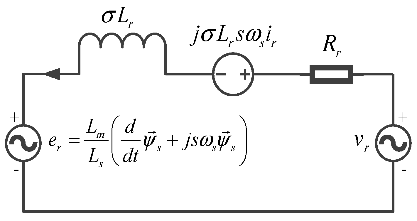
v r = L m L s d d t ψ s + j s ω s ψ s e r + R r i r + σ L r d d t + j s ω s i r U R L
From (7), it is clear that the rotor voltage might be separated into two terms: (1) er is the rotor EMF caused by the stator-flux linkage, and (2) URL is the voltage drop across the rotor transient inductance (σLr) and the rotor resistance. Based on (7), it is possible to realize the equivalent model of the DFIG from the rotor-side, which is illustrated in Figure 2.

3.2. Steady-State Analysis of DFIG

Since the stator-flux linkage in the SRF is constant, the transient process of the flux under normal operating conditions. The rotor EMF can therefore be simplified to
e r = L m L s j s ω s ψ s
From (4), the analytical expression for the stator voltage will be given by
v s = j ω s ψ s
Putting (9) into (8),
e r = L m L s s v s
The amplitude of the rotor EMF is given by
E r = L m L s s V s
Here, Vs is the rated stator voltage. From (11), it is clear that er is proportional to slip (s), which varies between –0.3 and 0.3. According to (11), it is obvious that the rotor EMF amplitude under normal conditions is quite small and at most 30% of the specified stator voltage. Thus, it will provide about 30% output of the generator rating; however, some safety margin must also be considered.

3.3. Transient Analyses of DFIG

This subsection discusses into extensive depth about the transient analyses of a DFIG under grid faults (i.e., symmetrical and asymmetrical). After a grid disturbance, the stator-flux behaviors after a grid fault can be segmented into its positive-sequence, negative-sequence, and transient components as
ψ s = ψ s p + ψ s n + ψ s d c

3.3.1. Symmetrical Grid Faults

The stator-flux linkage will include a transient component in the case of symmetrical fault and is given by
ψ s = 1 d V s j ω s ψ s p + d V s j ω s e t / τ s e j ω s t ψ s d c
In (13), d is the voltage dip level and τs (=Ls/Rs) is designated by the stator time constant of the flux linkage. Equation (13) can be decomposed into two terms: the positive-sequence component (Ψsp) and the other is the dc (natural) component (Ψsdc), which decays with τs. The negative-sequence component (Ψsn) will not exist in case of a symmetrical fault. Then, according to (8), the transient rotor EMF generated by the stator flux under symmetrical faults can now be represented by
e r = L m L s s 1 d V s 1 s d V s e t / τ s e j ω s t
It is obvious that the preliminary magnitude of transient EMF during under grid faults is comparatively larger than its normal value. Thus, the extreme amplitude of the transient rotor EMF is given by
E r max = L m L s V s s 1 d 1 s d
Considering the most serious scenario of a maximum voltage dip (d = 1) and s = –0.3, the starting strength of the rotor EMF during symmetrical faults can be approximated by using (16)
E r max s y m 1.3 L m L s V s
which is several times higher than its normal value and far exceeds the DC-link voltage from its rated value. The DC-link voltage will continue to surpass during serious grid voltage dips unless the ψsdc does not decay to some specific extend.

3.3.2. Asymmetrical Grid Faults

Based on the above analysis, it is understood that the stator affects the dynamic behavior of the rotor by injecting an EMF by the stator-flux linkage. The stator-flux linkage will also have negative-sequence components in case of asymmetrical faults. Expanding the expression (12)
ψ s = V s p j ω s e j ω s t + V s n j ω s e j ω s t + ψ s d c e t / τ s
In (17), Vsp and Vsn represent the amplitudes of the positive- and negative-sequence components of the stator voltage, respectively. Ψsdc is the amplitude of the initial stator dc flux, and its value is determined by the angle (φΨ0) between the Ψsp and Ψsn., The initial dc flux for asymmetrical grid faults differs from symmetrical grid faults in that it relies on the fault type and the time of occurrence. This induced dc component has the maximum value for φΨ0 = π and no dc component appears if φΨ0 = 0. Transforming (17) into the stationary rotor-reference frame, then
ψ s r = V s p j ω s e j s ω s t + V s n j ω s e j 2 s ω s t + ψ s d c e t 1 τ s + j ω r
From (18), the expression of the rotor EMF can be substituted as:
e r r = L m L s d d t ψ s r = L m L s s V s p e j ω s t + 2 s V s n e j 2 s ω s t 1 τ s + j ω r ψ s d c e t 1 τ s + j ω r
The term (1/ τs) can be ignored due to the large time constant of the stator flux. Considering the most serious scenario, i.e., phase-to-phase fault and the worst condition of a full voltage dip (d = 1, φΨ0 = π), Ψsdc is given by
ψ s d c = V s j ω s
The amplitudes of the Vsp and Vsn will be
V s p = 1 d 2 V s , V s n = d 2 V s
Substituting (20) and (21) into (19), the rotor EMF caused by the stator flux during asymmetrical faults will be expressed as
e r r = L m L s 0.5 s V s e j ω s t + 0.5 2 s V s e j 2 s ω s t 1 s e t 1 τ s + j ω r
The positive-sequence, negative-sequence, and transient components are related to s, (1-s), and (2-s), as can be seen from (22), respectively. Thus, the peak magnitude of the rotor transient EMF is given by
E r max = L m L s V s 0.5 s + 0.5 2 s 1 s
Considering the worst scenario when s = –0.3, the initial amplitude of the rotor EMF can be approximated by using (24)
E r max a s y m 2.6 L m L s V s
Obviously, the rotor EMF’s initial amplitude is high under asymmetrical grid faults, mainly as a result of its negative-sequence component. Based on the above analysis and from (16) and (24), it is simple to realize that the deepest asymmetrical fault (phase-to-phase) is far more pronounced compared to the symmetrical fault of the same voltage dip level.

4. Proposed Control Schemes

This section explains the proposed control scheme developed for the improved transient performance of the DFIG. As was stated in Section 1, the objectives of this study are to improve the ride-through operation of the DFIG by lowering transient rotor and stator currents, reducing electromagnetic torque oscillations, and improving DC-link voltage response. In this context, a combined control of active crowbars employed at the rotor-side and DC-link is proposed. Detailed theoretical explanation, designed procedures, mathematical formulations, and analyses of each active crowbar control scheme are provided in this section. A detailed explanation of control systems for RSC and GSC is here not included for conciseness; however, it can be found in [1,11,17]. The focus of this study is to investigate the impacts of active crowbars on the transient performance of the wind-driven DFIG system.

4.1. Proposed Control Scheme for LVRT Enhancement

The following subsections provide a detailed discussion and design of the proposed control strategies intended to facilitate the ride-through operations of the DFIG during grid faults. The primary objectives of an LVRT control strategy are to protect the RSC from transient currents and DC-link from overvoltages. The requirements for the successful implementation of the LVRT strategy are as follows:
i r 1.5 I r , r a t e d , i s 1.5 I s , r a t e d 0.85 V d c r e f v d c 1.15 V d c r e f
A combination of an active crowbar at the rotor-side and other parallel to DC-link is proposed and implemented in the next subsections to satisfy the aforementioned requirements (25) for LVRT.

4.1.1. Control Structure of Crowbar at Rotor-side

Crowbar protections are designed and put into place to safeguard the RSC from overcurrents. The crowbar is activated by isolating the RSC [21] when an aberrant situation is detected; its functionality effectively reduces transient rotor currents. Crowbar activation results in the loss of the controllability of the DFIG since it short-circuits the rotor windings during grid faults to limit the transient current. In this situation, the DFIG receives reactive power from the grid that results DC-link overvoltages. Furthermore, the reduced capacity of the RSC is a key obstacle, which can handle a limited transient current.
A parallel combination of the RCB and the rotor-crowbar resistors (RCR) is put in series between the DFIG’s rotor and the RSC. During the steady-state operations, the RCB is connected to the circuit. However, in case of a fault, the control system turns off the RCB and the rotor current starts to flow via RRCR to limit the fault current. The benefit of this setup (see Figure 3) is that it allows for interrupted control of the DFIG even when the operating conditions are abnormal. To determine the value of RRCR, the following expression is used.
R R C R = n R r
Here, n is a multiple of Rr. The RRCR should be carefully chosen as it has a direct impact on DFIG’s transient performance. It should be high enough to prevent the RSC current from exceeding its limits; however, selecting too large a value may increase the transient rotor voltage beyond its acceptable range and can cause huge ripples in the DC-link voltage. Therefore, a suitable selection of this resistance is important. According to [35], ‘n’ can be selected between 20 – 50. The total rotor resistance (Rr-trans.) during the fault becomes
R r t r a n s . = R r + R R C R = R r + n R r = R r ( 1 + n )
In this context, the transient rotor time constant during fault will be
τ r t r a n s . = L r t r a n s . R r t r a n s .
Here, Lr-trans. is the transient rotor inductance and is given by (29).
L r t r a n s . = L r + L s L m L s + L m

4.1.2. Control Structure of Crowbar at DC-link
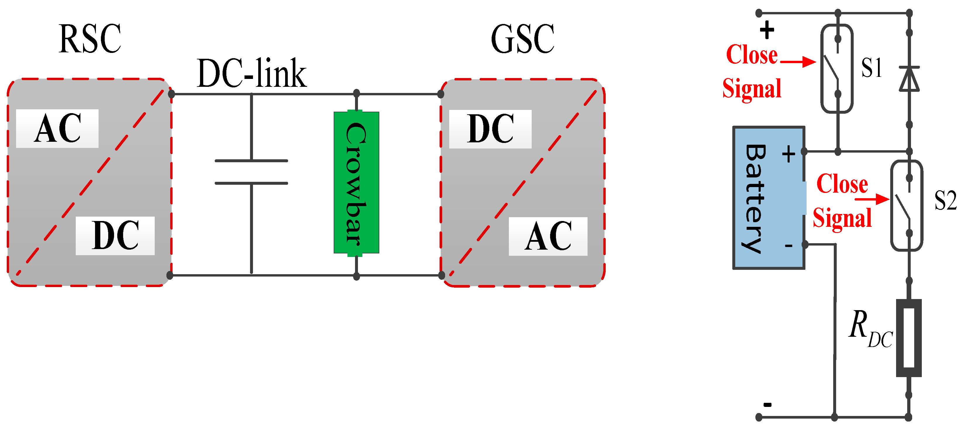
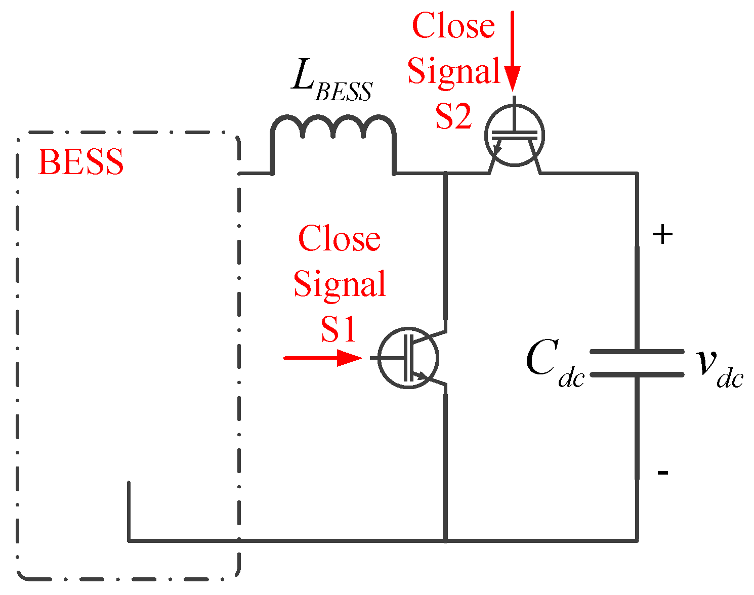
The active-power regulation of the system is the ultimate objective of integrating the ESDs [22], however that is outside the focus of this study. This work is limited to the application of an ESD for improved transient performance of the generator, and it is already available in literature [22,28]. In this paper, a battery is taken as an ESD. The schematic is presented in Figure 4, which comprises a DC-DC converter and a battery model. The ESD can provide power to the DC-link based on the voltage at the grid side. The type and control scheme of a battery-based ESD affects how well it performs for LVRT enhancement during grid faults. The authors used a battery model from MATLAB/Simulink library.
A switching function for activating the switch S1 is defined as
F s = 1 , v d c < 0.90 V d c r e f F s = 0 , v d c > 0.95 V d c r e f
A switching function for activating the switch S1 is defined as
Preprints 83592 i001
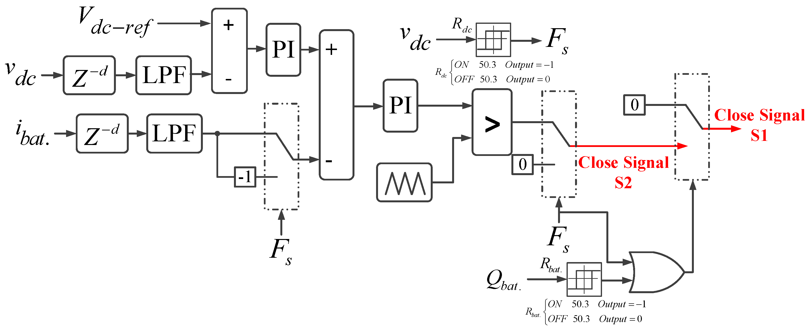
The schematic of the crowbar control structure at the DC-link is shown in Figure 5. It has two cascaded PI regulators for voltage and current controls, which tracks, respectively, the DC-link voltage (vdc) and ESD current (ibat.). The ESD manages the DC-link voltage and regulates the voltage variations by being charged and discharges to guarantee a consistent DC voltage. The current regulator’s output is compared with the carrier waveform (i.e., repeating sequence of triangle waveform). When exceeding the compared waveform, the output is sent to the switch S1, if Fs = 1.
The proposed control scheme also realizes the battery-charging process when both the two conditions are met.
F s = 0 , Q b a t . < 98 %
However, the process can be interrupted at any stage. For a fully-charged battery, the state-of-charge will be 100%. Upon fault detection, the ESD will be triggered to provide the transient EMF and facilitate voltage regulation.

5. Estimation of BESS Capacity for LVRT

The ESDs with appropriate storage capacity are normally installed inside the WECSs controls to improve its LVRT capabilities. The energy capacity of an ESD is determined in accordance to the system’s power regulation, as its primary function. However, it is beyond the scope of this paper. Here, the emphasis is on determining the suitable energy capability of an ESD for the ancillary control that can firmly support the transient conditions.
The mathematical expression describing the power flow of the DFIG-based WECS is given by
P g r i d = P s t a t o r + P r o t o r
In (32), Pgrid, Pstator, and Protor are the grid-side active power, stator power, and rotor power, respectively. Voltage dips at the grid side impede the delivery of entire generated output power which leads to an imbalance in the mechanical and electrical torques. Accordingly, the rotor speed will temporarily expedite during voltage dips, and its peak depends on d. The over-speeding of the rotor from its rated value is prevented and compensated for by activating the pitch-angle controller. Furthermore, the increased rotor speed converts a portion of the wind energy into mechanical energy, presenting the rotor KE which heavily depends on the wind-speed conditions. The energy flowing through the RSC consists of two parts: energy that is held in the DC-link and energy that is transferred to the grid through RSC.
During a severe fault, however, the Ps is restricted to zero. The required energy capacity of a battery energy storage system (BESS) is estimated as follows
P B E S S = P r o t o r = P d c l i n k + P g s c E B E S S = t s t a r t t f i n a l P B E S S t s t a r t t f i n a l P d c l i n k + t s t a r t t f i n a l P g s c
In the above expression, tinitial and tfinal are the instants of the fault occurring and clearing, respectively. Now, the complete expression for assessing the capacity of the BESS can be computed as
E B E S S = 1 2 C d c v d c 2 ( t f i n a l ) v d c 2 ( t s t a r t ) + d V g I g s c , max t f i n a l t s t a r t
In (34), Igsc, max is the maximum current-carrying capacity of the GSC, and Vg is the rated voltage at the point of common coupling. Using the above expression, the basic energy capacity of the BESS is approximated around 140 KW including some margins using the parameters given in Appendix-A, when d = 1; (tfinal - tstart) = 0.6 s are considered.

6. Results and Discussions

This section examines the performance of the proposed control schemes designed in Section 4 for enhancing the transient performance of a wind-power system during different grid faults and observing their effects on the system. The DFIG parameters had been taken from [11]. Simulation studies using MATLAB/Simulink are conducted to highlight the performances of the proposed control schemes.

6.1. Performance of the Proposed Control Scheme for Symmetrical Grid Fault

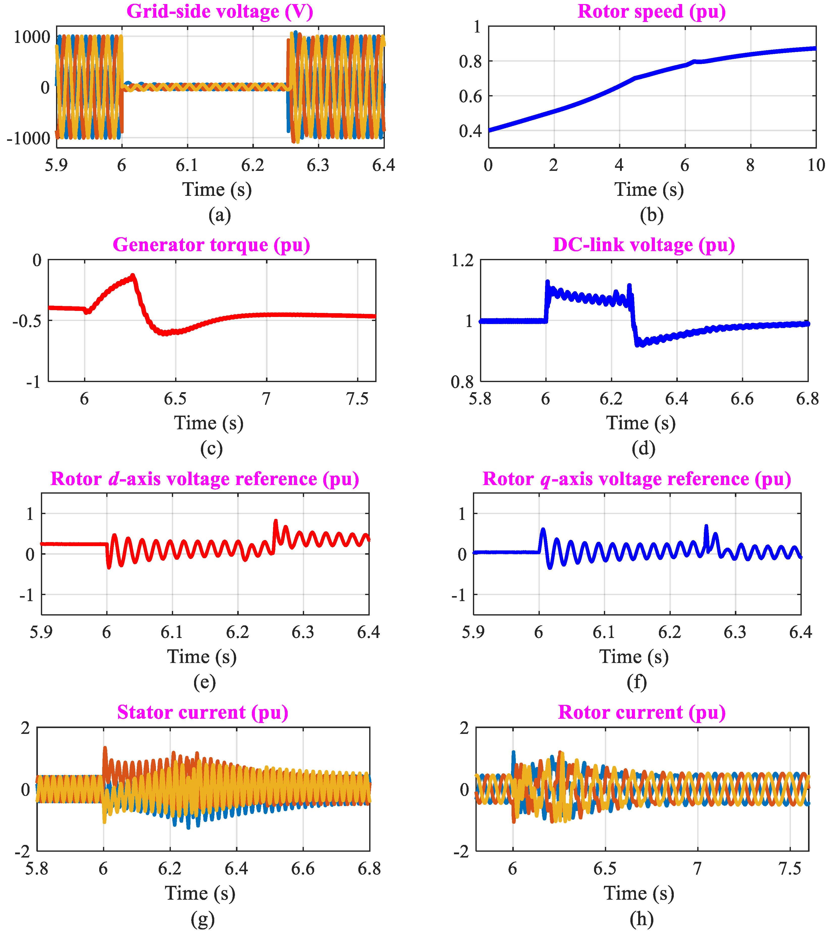
By applying a three-phase fault (step change) on the LV-side of the transformer from 6 s to 6.25 s, the system behavior is analyzed. Meanwhile, the grid-side voltage, which can be seen in Figure 6(a), instantaneously decreases to less than 10% of its normal operating value. Figure 6b–h presents the simulation results for the rotor speed, generator torque, DC-link voltage, rotor dq voltage references, stator current, and rotor current, respectively.
Figure. 6(b) illustrates that the effects of the fault on the rotor speed are negligible. The proposed controls efficiently reduce the oscillations of the generator torque, as demonstrated in Figure 6(c). Moreover, as seen in Figure 6(d), the DC-link voltage remains consistent within limits (25). Observing Figure 6(e)–(f), it is evident that the rotor dq voltage references contain transient components both during and after the fault; however, such transients are effectively limited by the proposed control schemes.
The analyses of Figure 6(g)–(h) show that the stator- and rotor-current transients are restricted to their acceptable current ranges (25). It is noteworthy that during a symmetrical grid fault, there is no possibility of stator- and rotor-current transients during grid fault, as the activation of active crowbars provide relief in dampening them effectively. Furthermore, it has been proved that the proposed control schemes work to successfully implement the LVRT operation while greatly reducing the effects of grid disturbances.

6.2. Performance of the Proposed Control Scheme for Asymmetrical Grid Fault

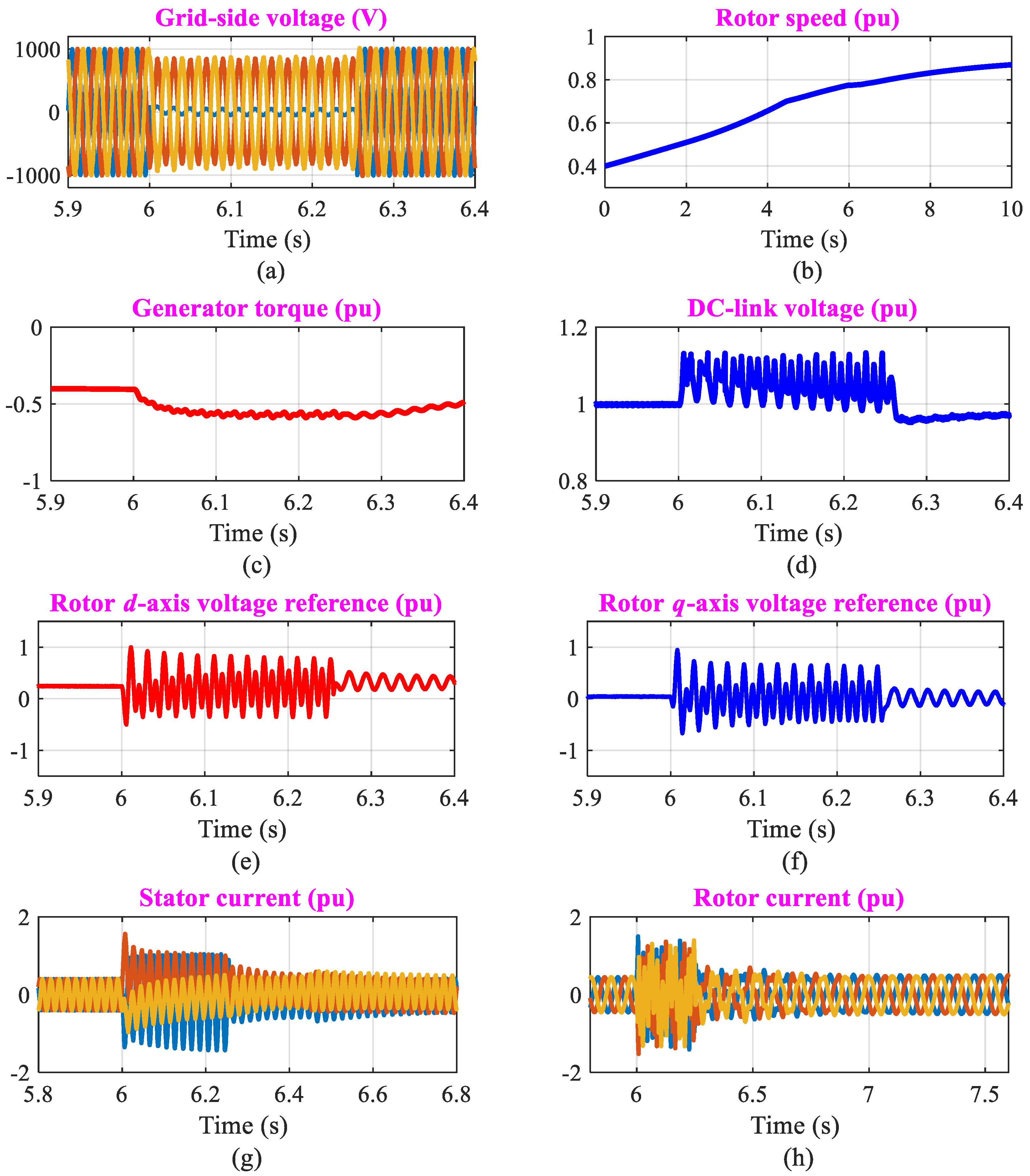
In this subsection, the implications of an asymmetrical grid fault are discussed, and its impacts on the system are examined herein. This is accomplished by applying a single-phase-to-ground fault is applied (see Figure 7(a)), with the same operating conditions as in the prior scenario. The simulation results are used to emphasize the behavior of the proposed control method, which are depicted in Figure 7. However, due to the higher DC stator-flux linkage [9], the variations in the selected waveforms (see Figure 7) are higher than they are for the symmetrical grid fault.
It has been noted from the analyses that the system performance using the proposed schemes is significantly improved in terms of reduced levels of transient rotor and stator currents as well as variations in the DC-link voltage, ensuring reliable power-system operation.

6.3. Performance Comparison

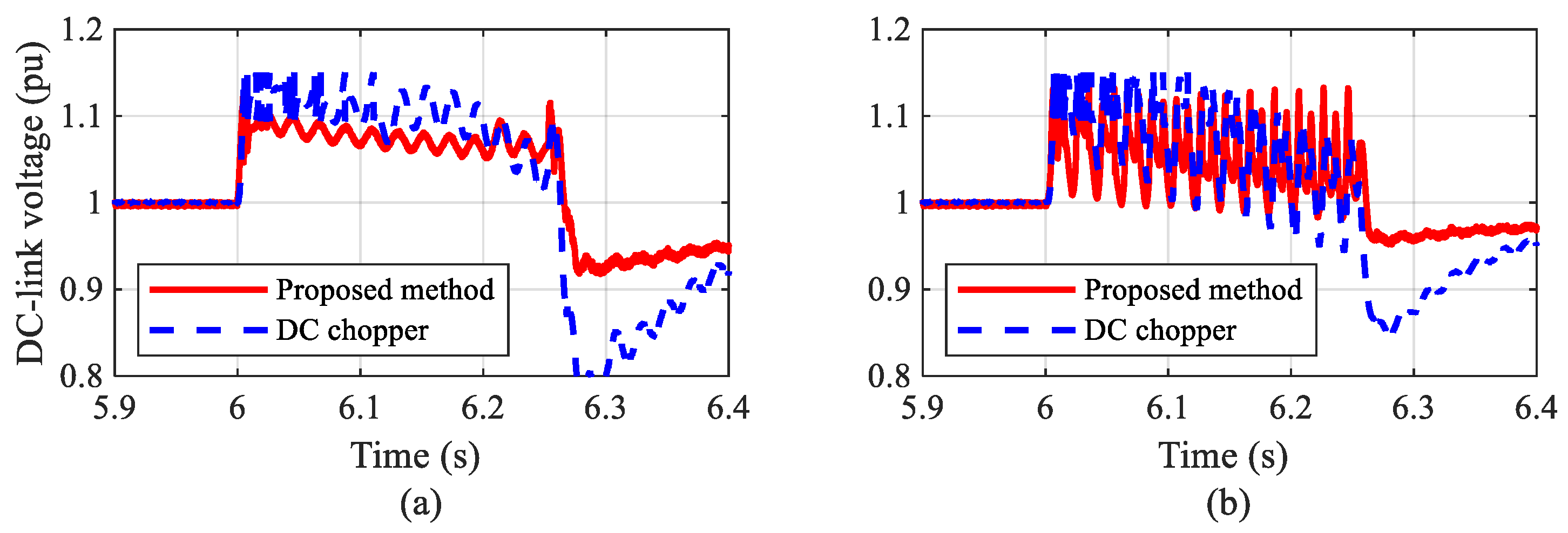
Finally, to validate the performance improvement of the proposed design, a comparative study with a DC-chopper is conducted. The system is simulated again for both the previously discussed cases and the same parameters are considered here. The waveforms of the DC-link voltage for symmetrical and asymmetrical grid faults are shown in Figure 8(a)–(b), respectively. The outcomes demonstrate the superior performance of the designed approach in alleviating the DC-link overvoltages, confirming its worth.

7. Conclusions

This study addressed the most critical issue — LVRT capability/transient performance of a DFIG-based WT system when connected to a power grid — and a hardware-based technical solution was presented. This paper can be concluded as follows:
A combination of active crowbars installed at the rotor-side and DC-link was designed and implemented to mitigate the impacts of the grid faults that can destroy the DC-link capacitor and cause enormous current stresses on wind-power converters. The outcomes demonstrated that this crowbar combination efficiently kept transient rotor and stator currents as well as DC-link voltage variations under permitted limits (25), which improved the DFIG’s LVRT functioning and increased system stability. Moreover, the electromagnetic torque oscillations were efficiently suppressed.

Funding

This research received no external funding.

Data Availability Statement

Not applicable.

Conflicts of Interest

The authors declare no conflict of interest.

Appendix A

Table A1. Parameter of 1.5 MW DFIGURE
Parameter Value Unit
Generator rated power 1.5 MW
Rated stator voltage 690 V
Rated frequency 50 Hz
Pole-pair number 2 Nos.
Stator winding resistance 2.65
Stator leakage inductance 0.1687 mH
Rotor winding resistance 2.63
Rotor leakage inductance 0.1337 mH
Magnetizing inductance 5.4749 mH
Rotational inertia 3 s

References

  1. Salama, H.S.; Vokony, I. Voltage and Frequency Control of Balanced/Unbalanced Distribution System Using the SMES System in the Presence of Wind Energy. Electricity 2021, 2, 205–224. [Google Scholar] [CrossRef]
  2. Ali, M.A.S.; Mehmood, K.K.; Kim, C.-H. Full operational regimes for SPMSG-based WECS using generation of active current references. Int. J. Electr. Power Energy Syst. 2019, 112, 428–441. [Google Scholar] [CrossRef]
  3. Huang, Q.; Zou, X.; Zhu, D.; Kang, Y. Scaled current tracking control for doubly fed induction generator to ride through serious grid faults. IEEE Trans. Power Electron. 2016, 31, 2150–2165. [Google Scholar] [CrossRef]
  4. Alsmadi, Y.M.; et al. Detailed investigation and performance improvement of the dynamic behavior of grid-connected DFIG-based wind turbines under LVRT conditions. IEEE Trans. Ind. Appl. 2018, 54, 4795–4812. [Google Scholar] [CrossRef]
  5. Firouzi, M.; Gharehpetian, G.B. LVRT performance enhancement of DFIG-based wind farms by capacitive bridge-type fault current limiter. IEEE Trans. Sustain. Energy 2018, 9, 1118–1125. [Google Scholar] [CrossRef]
  6. Ali, M.A.S.; Mehmood, K.K.; Baloch, S.; Kim, C.-H. Wind-Speed Estimation and Sensorless Control for SPMSG-Based WECS Using LMI-Based SMC. IEEE Access 2020, 8, 26524–26535. [Google Scholar] [CrossRef]
  7. Zhu, D.; et al. Feedforward current references control for DFIG-based wind turbine to improve transient control performance during grid faults. IEEE Trans. Energy Convers. 2018, 33, 670–681. [Google Scholar] [CrossRef]
  8. Haidar, A.M.A.; Muttaqi, K.M.; Hagh, M.T. A coordinated control approach for DC link and rotor crowbars to improve fault ride-through of DFIG-based wind turbine. IEEE Trans. Ind. Appl. 2017, 53, 4073–4086. [Google Scholar] [CrossRef]
  9. Xiao, S.; Yang, G.; Zhou, H.; Geng, H. An LVRT control strategy based on flux linkage tracking for DFIG-based WECS. IEEE Trans. Ind. Electron. 2013, 60, 2820–2832. [Google Scholar] [CrossRef]
  10. Zhou, L.; Liu, J.; Zhou, S. Improved demagnetization control of a doubly-fed induction generator under balanced grid fault. IEEE Trans. Power Electron. 2015, 30, 6695–6705. [Google Scholar] [CrossRef]
  11. Ali, M.A.S.; Mehmood, K.K.; Baloch, S.; Kim, C.-H. Modified rotor-side converter control design for improving the LVRT capability of a DFIG-based WECS. Electr. Power Syst. Res. 2020, 186, 106403. [Google Scholar] [CrossRef]
  12. Li, X.-M.; Zhang, X.-M.; Lin, Z.-W.; Niu, Y.-G. An improved flux magnitude and angle control with LVRT capability for DFIGs. IEEE Trans. Power Syst. 2018, 33, 3845–3853. [Google Scholar] [CrossRef]
  13. Majout, B.; et al. Improvement of PMSG-based wind energy conversion system using developed sliding mode control. Energies, 2022, 15, 1625. [Google Scholar] [CrossRef]
  14. Morshed, M.J.; Fekih, A. A new fault ride-through control for DFIG-based wind energy systems. Electr. Power Syst. Res. 2017, 146, 258–269. [Google Scholar] [CrossRef]
  15. Geng, H.; Liu, C.; Yang, G. LVRT capability of DFIG-based WECS under asymmetrical grid fault condition. IEEE Trans. Ind. Electron. 2013, 60, 2495–2509. [Google Scholar] [CrossRef]
  16. Xie, D.; et al. A comprehensive LVRT control scheme for DFIG wind turbines with enhanced reactive power support. IEEE Trans. Power Syst. 2013, 28, 3302–3310. [Google Scholar] [CrossRef]
  17. Ali, M.A.S. Enhanced transient performance of wind-driven PMSG: A revised control structure of wind-power converters. Adv. Electr. Comput. Eng. 2022, 2, 61–70. [Google Scholar] [CrossRef]
  18. Zhang, Y.; Liu, J.; Zhou, M.; Li, C.; Lv, Y. ; Double impedance-substitution control of DFIG based wind energy conversion system. Energies, 2022, 15, 5739. [Google Scholar] [CrossRef]
  19. Ma, Y.; et al. Modeling and transient stability analysis for Type-3 wind turbines using singular perturbation and Lyapunov methods. IEEE Trans. Ind. Electron. 2022, 1–1. [Google Scholar] [CrossRef]
  20. Dang., H.P.; Pico, H.N.V. Blackstart and fault ride-through capability of DFIG-based wind turbines. IEEE Trans. Smart Grid 2022, 1–1. [Google Scholar] [CrossRef]
  21. Jalilian., A.; Naderi, S.B.; Negnevitsky, M.; Hagh, M.T.; Muttaqi, K.M. Controllable DC-link fault current limiter augmentation with DC chopper to improve fault ride-through of DFIGURE. IET Renew. Power Gener 2017, 11, 1304–1304. [Google Scholar] [CrossRef]
  22. Tabosa da Silva, P.L.; Rosas, P.A.C.; Castro, J.F.C.; Marques, D.d.C.; Aquino, R.R.B.; Rissi, G.F.; Neto, R.C.; Barbosa, D.C.P. Power Smoothing Strategy for Wind Generation Based on Fuzzy Control Strategy with Battery Energy Storage System. Energies 2023, 16, 6017. [Google Scholar] [CrossRef]
  23. Rashid, G.; Ali, M.H. Nonlinear control-based modified BFCL for LVRT capacity enhancement of DFIG-based wind farm. IEEE Trans. Energy Convers. 2017, 32, 284–295. [Google Scholar] [CrossRef]
  24. Hossain., M.A.; et al. Protecting DFIG-based multi-machine power system under transient-state by nonlinear adaptive backstepping controller-based capacitive BFCL. IET Gener. Transm. Distrib. 2022, 16, 4528–4528. [Google Scholar] [CrossRef]
  25. Padmaja, A.; et al. Design of capacitive bridge fault current limiter for low-voltage ride-through capacity enrichment of doubly fed induction generator-based wind farm. Sustainability 2021, 13, 6656. [Google Scholar] [CrossRef]
  26. Sadi, M.A.H.; AbuHussein, A.; Shoeb, M.A. Transient performance improvement of power systems using fuzzy logic controlled capacitive-bridge type fault current limiter. IEEE Trans. Power Syst. 2020, 36, 323–335. [Google Scholar] [CrossRef]
  27. Gounder., Y.K..; Nanjundappan, D.; Boominathan, V. Enhancement of transient stability of distribution system with SCIG and DFIG based wind farms using STATCOM. IET Renew. Power Gener. 2016, 10, 1171–1180. [Google Scholar] [CrossRef]
  28. Shen, Y.-W.; et al. Advanced auxiliary control of an energy storage device for transient voltage support of a doubly fed induction generator. IEEE Trans. Sustain. Energy 2016, 7, 63–76. [Google Scholar] [CrossRef]
  29. Wessels, C.; Gebhardt, F.; Fuchs, F.W. Fault ride-through of a DFIG wind turbine using a dynamic voltage restorer during symmetrical and asymmetrical grid faults. IEEE Trans. Power Electron. 2011, 26, 807–815. [Google Scholar] [CrossRef]
  30. Wang, X.; Peng, L. Dynamic voltage equalization control of D-STATCOM under unbalanced grid faults in low-voltage network. IEEE Trans. Power Electron. 2022, 1–14. [Google Scholar] [CrossRef]
  31. Xiao, F.; Xia, Y.; Zhang, K.; Zhang, Z.; Yin, X. Fault characteristics analysis of DFIGWT in whole LVRT process considering control strategy switching between RSC and crowbar. Int. J. Electr. Power Energy Syst. 2023, 145, 108615. [Google Scholar] [CrossRef]
  32. Blaabjerg, F.; Xu, D.; Chen, W.; Zhu, N. Advanced Control of Doubly Fed Induction Generator for Wind Power Systems; Wiley-IEEE Press: Piscataway, NJ, USA, 2018. [Google Scholar]
  33. Abad, G.; Lopez, J.; Rodriguez, M.; Marroyo, L.; Iwanski, G. Doubly Fed Induction Machine: Modeling and Control for Wind Energy Generation; Wiley-IEEE Press: Piscataway, NJ, USA, 2011. [Google Scholar]
  34. Wu, B.; Lang, Y.; Zargari, N.; Kouro, S. Power Conversion and Control of Wind Energy Systems; Wiley-IEEE Press: Piscataway, NJ, USA, 2011. [Google Scholar]
  35. Noubrik, A.; Chrifi-Alaoui, L.; Bussy, P.; Benchaib, A. Analysis and simulation of a crowbar protection for DFIG wind application during power systems disturbances. J. Mech. Eng. Autom. 2011, 1, 303–312. [Google Scholar]
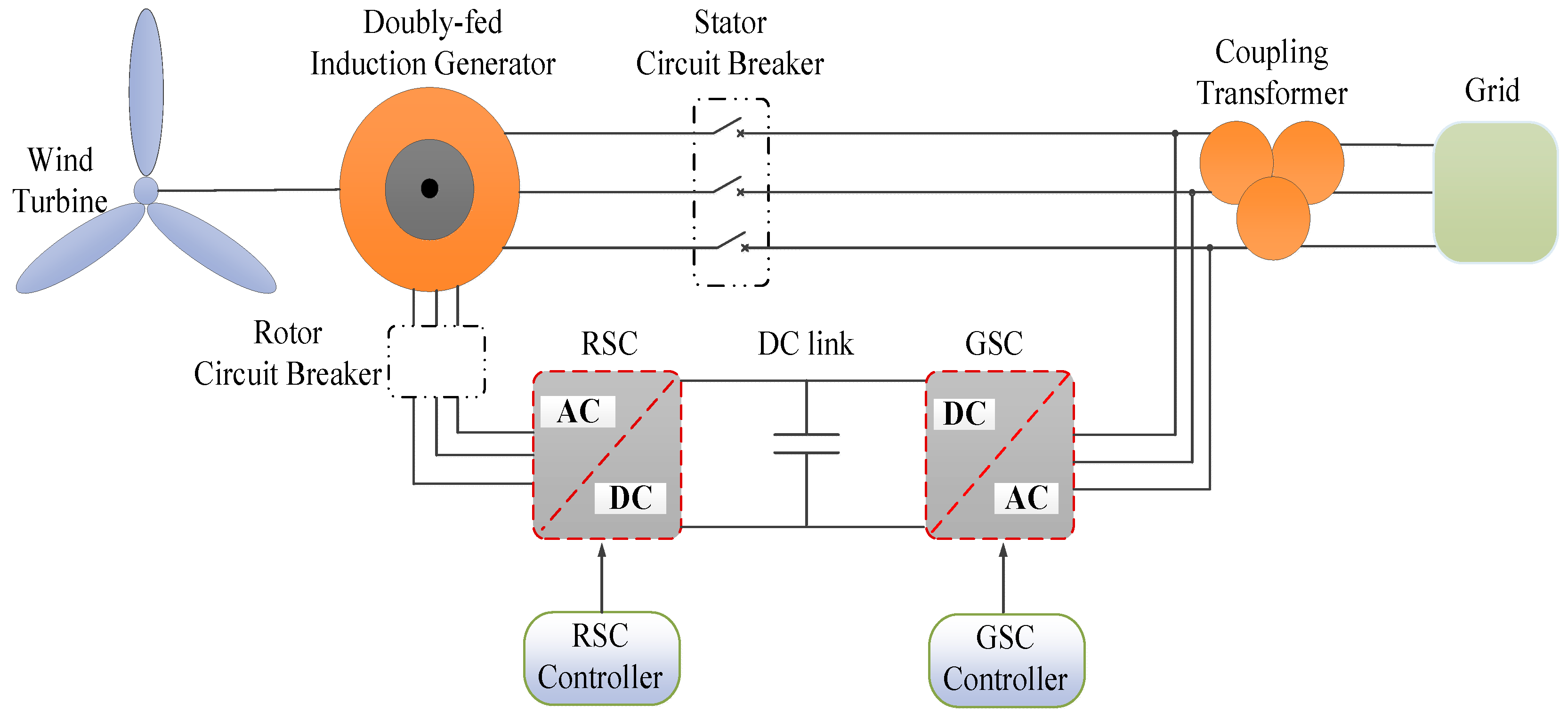
Figure 1. Overall diagram of a DFIG-based WECS.
Preprints 83592 g001
Figure 2. Equivalent model of DFIG from the rotor-side.
Preprints 83592 g002
Figure 3. Schematic of the crowbar control system at rotor-side.
Preprints 83592 g003
Figure 4. Schematic of DC-DC converter.
Preprints 83592 g004
Figure 5. Schematic of the crowbar control system at DC-link.
Preprints 83592 g005
Figure 6. Simulation results of the selected waveforms via proposed control schemes under symmetrical grid voltage fault.
Preprints 83592 g006
Figure 7. Simulation results of the selected waveforms via proposed control schemes under symmetrical grid voltage fault.
Preprints 83592 g007
Figure 8. Comparative results: (a) symmetrical grid fault and (b) asymmetrical grid fault.
Preprints 83592 g008
Disclaimer/Publisher’s Note: The statements, opinions and data contained in all publications are solely those of the individual author(s) and contributor(s) and not of MDPI and/or the editor(s). MDPI and/or the editor(s) disclaim responsibility for any injury to people or property resulting from any ideas, methods, instructions or products referred to in the content.
Copyright: This open access article is published under a Creative Commons CC BY 4.0 license, which permit the free download, distribution, and reuse, provided that the author and preprint are cited in any reuse.
Prerpints.org logo

Preprints.org is a free preprint server supported by MDPI in Basel, Switzerland.

Subscribe

© 2024 MDPI (Basel, Switzerland) unless otherwise stated